The Finite Element Method for the Analysis of Non-Linear and ...
The Finite Element Method for the Analysis of Non-Linear and ...
The Finite Element Method for the Analysis of Non-Linear and ...

You also want an ePaper? Increase the reach of your titles
YUMPU automatically turns print PDFs into web optimized ePapers that Google loves.
<strong>The</strong> <strong>Finite</strong> <strong>Element</strong> <strong>Method</strong> <strong>for</strong> <strong>the</strong> <strong>Analysis</strong> <strong>of</strong><br />
<strong>Non</strong>-<strong>Linear</strong> <strong>and</strong> Dynamic Systems<br />
Pr<strong>of</strong>. Dr. Eleni Chatzi<br />
Lecture 14 - 20 December, 2010<br />
Institute <strong>of</strong> Structural Engineering <strong>Method</strong> <strong>of</strong> <strong>Finite</strong> <strong>Element</strong>s II 1
Special Topics<br />
<strong>The</strong> st<strong>and</strong>ard finite element method has been used with great success<br />
in many fields with both academic <strong>and</strong> industrial applications. It is<br />
however not without limitations. Due to mesh-based interpolation,<br />
distorted or low quality meshes lead to higher errors, necessitate<br />
remeshing, a time <strong>and</strong> human labor consuming task, which is not<br />
guaranteed to be feasible in finite time <strong>for</strong> complex three-dimensional<br />
geometries. Additionally, <strong>the</strong>y are not well suited to treat problems<br />
with discontinuities that do not align with element edges.<br />
Alternative/Extended Approaches<br />
Meshless <strong>Method</strong>s<br />
Multigrid <strong>Method</strong>s<br />
Extended <strong>Finite</strong> <strong>Element</strong> methods<br />
Institute <strong>of</strong> Structural Engineering <strong>Method</strong> <strong>of</strong> <strong>Finite</strong> <strong>Element</strong>s II 2
Special Topics<br />
Meshless <strong>Method</strong>s<br />
Traditional simulation algorithms relied on a grid or a mesh, Meshless<br />
methods in contrast use <strong>the</strong> geometry <strong>of</strong> <strong>the</strong> simulated object directly <strong>for</strong><br />
calculations. Meshless (or Meshfree) methods (MMs) were born with <strong>the</strong><br />
objective <strong>of</strong> eliminating part <strong>of</strong> <strong>the</strong> difficulties associated with reliance on a<br />
mesh to construct <strong>the</strong> approximation.<br />
Institute <strong>of</strong> Structural Engineering <strong>Method</strong> <strong>of</strong> <strong>Finite</strong> <strong>Element</strong>s II 3
Special Topics<br />
Meshless <strong>Method</strong>s<br />
Meshless approximations <strong>for</strong> a scalar function u in terms <strong>of</strong> <strong>the</strong><br />
material (Lagrangian) coordinates can be written as<br />
u(x, t) = ∑ i∈S<br />
N i (x)u i (t)<br />
where N i : Ω → R are <strong>the</strong> shape functions <strong>and</strong> <strong>the</strong> u i are <strong>the</strong> nodal<br />
values at particle i located at position x i <strong>and</strong> S is <strong>the</strong> set <strong>of</strong> nodes i<br />
<strong>for</strong> which N i (x) ≠ 0. In contrast to FEM, <strong>the</strong> shape functions are<br />
only approximants <strong>and</strong> not interpolants, since u i ≠ u(x i ).<br />
<strong>The</strong>re<strong>for</strong>e, special techniques are needed to treat displacement<br />
boundary conditions.<br />
Institute <strong>of</strong> Structural Engineering <strong>Method</strong> <strong>of</strong> <strong>Finite</strong> <strong>Element</strong>s II 4
Special Topics<br />
Meshless <strong>Method</strong>s<br />
Advantages<br />
problems with moving<br />
discontinuities such as crack<br />
propagation <strong>and</strong> phase<br />
trans<strong>for</strong>mation can be treated<br />
with ease<br />
large de<strong>for</strong>mation can be<br />
h<strong>and</strong>led more robustly<br />
higher-order continuous<br />
shape functions<br />
non-local interpolation<br />
character<br />
no mesh alignment sensitivity.<br />
Disadvantages<br />
<strong>The</strong> MMs shape functions<br />
are rational functions which<br />
requires high-order<br />
integration scheme to be<br />
correctly computed<br />
<strong>The</strong> treatment <strong>of</strong> essential<br />
boundary conditions is not as<br />
straight<strong>for</strong>ward<br />
<strong>The</strong>y do not satisfy <strong>the</strong><br />
Kronecker delta property<br />
In general, <strong>the</strong> computational<br />
cost <strong>of</strong> MMs is higher than<br />
one <strong>of</strong> FEM.<br />
Institute <strong>of</strong> Structural Engineering <strong>Method</strong> <strong>of</strong> <strong>Finite</strong> <strong>Element</strong>s II 5
Special Topics<br />
Multigrid <strong>Method</strong>s<br />
Multigrid (MG) methods in numerical analysis are a group <strong>of</strong><br />
algorithms <strong>for</strong> solving differential equations using a hierarchy <strong>of</strong><br />
discretizations. <strong>The</strong>y are a class <strong>of</strong> techniques very useful in<br />
problems exhibiting multiple scales <strong>of</strong> behavior. <strong>The</strong>y are fast linear<br />
iterative solvers based on <strong>the</strong> multilevel or multi-scale paradigm.<br />
<strong>The</strong> typical application <strong>for</strong><br />
multigrid is in <strong>the</strong><br />
numerical solution <strong>of</strong><br />
elliptic partial differential<br />
equations in two or more<br />
dimensions.<br />
Institute <strong>of</strong> Structural Engineering <strong>Method</strong> <strong>of</strong> <strong>Finite</strong> <strong>Element</strong>s II 6
Special Topics<br />
Multigrid <strong>Method</strong>s<br />
Institute <strong>of</strong> Structural Engineering <strong>Method</strong> <strong>of</strong> <strong>Finite</strong> <strong>Element</strong>s II 7
Special Topics<br />
Multigrid <strong>Method</strong>s<br />
<strong>The</strong>re are many variations <strong>of</strong> multigrid algorithms, but <strong>the</strong> common<br />
features are that a hierarchy <strong>of</strong> discretizations (grids) is considered.<br />
<strong>The</strong> important steps are:<br />
Smoothing Per<strong>for</strong>m some steps <strong>of</strong> a basic method in order to<br />
smooth out <strong>the</strong> error.<br />
Restriction Restrict <strong>the</strong> current state <strong>of</strong> <strong>the</strong> problem to a<br />
subset <strong>of</strong> <strong>the</strong> grid points, <strong>the</strong> so-called “coarse grid”, <strong>and</strong> solve<br />
<strong>the</strong> resulting projected problem.<br />
Interpolation or Prolongation Interpolate <strong>the</strong> coarse grid<br />
solution back to <strong>the</strong> original grid, <strong>and</strong> per<strong>for</strong>m a number <strong>of</strong><br />
steps <strong>of</strong> <strong>the</strong> basic method again.<br />
Institute <strong>of</strong> Structural Engineering <strong>Method</strong> <strong>of</strong> <strong>Finite</strong> <strong>Element</strong>s II 8
Special Topics<br />
Multigrid <strong>Method</strong>s - Adaptive Mesh<br />
Adaptive multigrid exhibits adaptive mesh refinement, that is, it<br />
adjusts <strong>the</strong> grid as <strong>the</strong> computation proceeds, in a manner dependent<br />
upon <strong>the</strong> computation itself. <strong>The</strong> idea is to increase resolution <strong>of</strong> <strong>the</strong><br />
grid only in regions <strong>of</strong> <strong>the</strong> solution where it is needed.<br />
Institute <strong>of</strong> Structural Engineering <strong>Method</strong> <strong>of</strong> <strong>Finite</strong> <strong>Element</strong>s II 9
Special Topics<br />
Multigrid <strong>Method</strong>s<br />
Advantages<br />
MG can be applied in combination with any <strong>of</strong> <strong>the</strong> common<br />
discretization techniques.<br />
Multigrid is among <strong>the</strong> fastest solution techniques known today.<br />
In contrast to o<strong>the</strong>r methods, multigrid is general in that it can<br />
treat arbitrary regions <strong>and</strong> boundary conditions.<br />
Multigrid does not depend on <strong>the</strong> separability <strong>of</strong> <strong>the</strong> equations<br />
or o<strong>the</strong>r special properties <strong>of</strong> <strong>the</strong> equation.<br />
MG is also directly applicable to more complicated,<br />
non-symmetric <strong>and</strong> nonlinear systems <strong>of</strong> equations.<br />
Can be very easily parallelized.<br />
Institute <strong>of</strong> Structural Engineering <strong>Method</strong> <strong>of</strong> <strong>Finite</strong> <strong>Element</strong>s II 10
Special Topics<br />
<strong>The</strong> Extended <strong>Finite</strong> <strong>Element</strong> <strong>Method</strong> (XFEM)<br />
<strong>The</strong> Extended <strong>Finite</strong> <strong>Element</strong> <strong>Method</strong> is a numerical method that<br />
enables a local enrichment <strong>of</strong> approximation spaces. <strong>The</strong> enrichment<br />
is realized through <strong>the</strong> partition <strong>of</strong> unity concept.<br />
<strong>The</strong> method is useful <strong>for</strong> <strong>the</strong> approximation <strong>of</strong> solutions with<br />
pronounced non-smooth characteristics in small parts <strong>of</strong> <strong>the</strong><br />
computational domain, <strong>for</strong> example near discontinuities <strong>and</strong><br />
singularities. In <strong>the</strong>se cases, st<strong>and</strong>ard numerical methods such as <strong>the</strong><br />
FEM <strong>of</strong>ten exhibit poor accuracy.<br />
<strong>The</strong> XFEM <strong>of</strong>fers significant advantages by enabling optimal<br />
convergence rates <strong>for</strong> <strong>the</strong>se applications.<br />
Institute <strong>of</strong> Structural Engineering <strong>Method</strong> <strong>of</strong> <strong>Finite</strong> <strong>Element</strong>s II 11
Special Topics<br />
XFEM - Motivation<br />
Modeling <strong>of</strong> discontinuities, ex. structural flaws (cracks, holes)<br />
Institute <strong>of</strong> Structural Engineering <strong>Method</strong> <strong>of</strong> <strong>Finite</strong> <strong>Element</strong>s II 12
Special Topics<br />
XFEM - Motivation<br />
Modeling <strong>of</strong> complicated crack geometries (ex. non planar cracks)<br />
A T-Joint with Crack on a<br />
Given Curved Plane<br />
Institute <strong>of</strong> Structural Engineering <strong>Method</strong> <strong>of</strong> <strong>Finite</strong> <strong>Element</strong>s II 13
Special Topics<br />
XFEM vs FEM<br />
- XFEM locally enrich <strong>the</strong> st<strong>and</strong>ard FE approximation with local<br />
partitions <strong>of</strong> unity enrichment functions<br />
- This allows <strong>for</strong> <strong>the</strong> separation <strong>of</strong> geometry from <strong>the</strong> mesh.<br />
St<strong>and</strong>ard FEM<br />
X-FEM<br />
Institute <strong>of</strong> Structural Engineering <strong>Method</strong> <strong>of</strong> <strong>Finite</strong> <strong>Element</strong>s II 14
Special Topics<br />
XFEM Scheme<br />
<strong>The</strong> conventional shape function space is enriched with a set <strong>of</strong><br />
enrichment functions H(x) <strong>and</strong> F j (x)<br />
u h (x) =<br />
n∑ ∑n J<br />
N I (x)u I + N I (x)H(x)a I +<br />
I=1<br />
Tip Enrichment<br />
I=1<br />
n T ∑<br />
I=1<br />
⎡<br />
⎣N I (x)<br />
4∑<br />
j=1<br />
F j (x)b jI<br />
⎤<br />
⎦<br />
F j (r(x), θ(x)) = { √ r sin θ 2 , √ r cos θ 2 , √ r sin θ 2 sin θ, √ r cos θ 2 sin θ} j=1,..,4<br />
Jump Enrichment<br />
H(X) =<br />
{<br />
1 above Γ + c<br />
0 bellow Γ − c<br />
Institute <strong>of</strong> Structural Engineering <strong>Method</strong> <strong>of</strong> <strong>Finite</strong> <strong>Element</strong>s II 15
Special Topics<br />
XFEM Scheme - Tip <strong>and</strong> Jump Enrichments<br />
Institute <strong>of</strong> Structural Engineering <strong>Method</strong> <strong>of</strong> <strong>Finite</strong> <strong>Element</strong>s II 16
Special Topics<br />
XFEM Applications - Composite Materials<br />
G XFEM<br />
= 4.762<br />
G ABAQUS<br />
= 4.703<br />
Gexp eriment<br />
= 4.784<br />
[lb in/in^2]<br />
Hart D., NSWCCD [2006]<br />
5<br />
4.5<br />
4<br />
3.5<br />
3<br />
G<br />
2.5<br />
2<br />
1.5<br />
1<br />
0.5<br />
0<br />
0 0.1 0.2 0.3 0.4 0.5 0.6 0.7 0.8 0.9 1<br />
coordinate along crack<br />
Institute <strong>of</strong> Structural Engineering <strong>Method</strong> <strong>of</strong> <strong>Finite</strong> <strong>Element</strong>s II 17
Special Topics<br />
XFEM Applications - Crack Growth<br />
Load P<br />
6.25<br />
Unit: mm<br />
Simplification<br />
BC 1<br />
Fix U,V<br />
15.63<br />
7.813<br />
BC 2<br />
Fix U<br />
35.0<br />
6.25<br />
37.5<br />
100<br />
Institute <strong>of</strong> Structural Engineering <strong>Method</strong> <strong>of</strong> <strong>Finite</strong> <strong>Element</strong>s II 18
Special Topics<br />
Crack Initiation Site:<br />
Experimental Observation<br />
Institute <strong>of</strong> Structural Engineering <strong>Method</strong> <strong>of</strong> <strong>Finite</strong> <strong>Element</strong>s II 19
Special Topics<br />
XFEM Applications - Crack Growth<br />
Institute <strong>of</strong> Structural Engineering <strong>Method</strong> <strong>of</strong> <strong>Finite</strong> <strong>Element</strong>s II 20
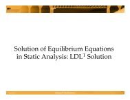
Introduction to FEM S<strong>of</strong>tware<br />
XFEM Applications - Crack Growth<br />
*<strong>The</strong> section on Introduction to FEM S<strong>of</strong>tware is based on<br />
Pr<strong>of</strong>. M. Faber’s notes <strong>of</strong> <strong>the</strong> FEM II course - Fall 2009<br />
<strong>Method</strong> <strong>of</strong> <strong>Finite</strong> <strong>Element</strong>s II<br />
1<br />
Institute <strong>of</strong> Structural Engineering <strong>Method</strong> <strong>of</strong> <strong>Finite</strong> <strong>Element</strong>s II 21
Introduction to FEM S<strong>of</strong>tware<br />
Overview<br />
FEM development<br />
Introduction to <strong>the</strong> use <strong>of</strong> <strong>Finite</strong> <strong>Element</strong>s<br />
Modeling <strong>the</strong> physical problem<br />
<strong>Finite</strong> elements as a tool <strong>for</strong> computer aided design <strong>and</strong><br />
assessment<br />
An overview <strong>of</strong> FEM s<strong>of</strong>tware (open source <strong>and</strong> commercial)<br />
Example: ABAQUS<br />
Institute <strong>of</strong> Structural Engineering <strong>Method</strong> <strong>of</strong> <strong>Finite</strong> <strong>Element</strong>s II 22
Introduction to FEM S<strong>of</strong>tware<br />
FE development<br />
FEM development<br />
FE is <strong>the</strong> confluence <strong>of</strong> three ingredients: matrix structural<br />
analysis, variational approach <strong>and</strong> computer<br />
1950s, M.J. Turner at Boeing (aerospace industry in general):<br />
Direct Stiffness <strong>Method</strong><br />
Academia: J.H. Argyris, R.W. Clough (name “finite element),<br />
H.C. Martin <strong>and</strong> O.C. Zienkiewicz popularization<br />
1960s, Melosh <strong>and</strong> De Veubeke: Variational Approach<br />
Commercial finite element computer codes<br />
Institute <strong>of</strong> Structural Engineering <strong>Method</strong> <strong>of</strong> <strong>Finite</strong> <strong>Element</strong>s II 23
Introduction to FEM S<strong>of</strong>tware<br />
FE Basics<br />
Within <strong>the</strong> framework <strong>of</strong> continuum mechanics dependencies<br />
between geometrical <strong>and</strong> physical quantities are <strong>for</strong>mulated on a<br />
differentially small element <strong>and</strong> <strong>the</strong>n extended to <strong>the</strong> whole<br />
continuum<br />
As a result we obtain differential, partial differential or integral<br />
equations <strong>for</strong> which, generally, an analytical solution is not<br />
available <strong>the</strong>y have to be solved using some numerical<br />
procedure<br />
MFE is based on <strong>the</strong> physical discretization <strong>of</strong> <strong>the</strong> observed<br />
domain, thus reducing <strong>the</strong> number <strong>of</strong> <strong>the</strong> degrees <strong>of</strong> freedom;<br />
moreover <strong>the</strong> governing equations are in general algebraic<br />
Institute <strong>of</strong> Structural Engineering <strong>Method</strong> <strong>of</strong> <strong>Finite</strong> <strong>Element</strong>s II 24
Introduction to FEM S<strong>of</strong>tware<br />
FE Steps<br />
Continuum is discretized in a mesh <strong>of</strong> finite elements<br />
<strong>Element</strong>s are connected at nodes located on element boundaries<br />
State <strong>of</strong> de<strong>for</strong>mation, stresses, etc. in each element is described<br />
by interpolation (shape) functions <strong>and</strong> corresponding values in<br />
<strong>the</strong> nodes; <strong>the</strong>se node values are basic unknowns <strong>of</strong> <strong>the</strong> method<br />
<strong>of</strong> finite elements<br />
<strong>The</strong> way in which <strong>the</strong>se three steps are approached has a great<br />
influence on <strong>the</strong> results <strong>of</strong> <strong>the</strong> calculations<br />
Institute <strong>of</strong> Structural Engineering <strong>Method</strong> <strong>of</strong> <strong>Finite</strong> <strong>Element</strong>s II 25
Introduction to FEM S<strong>of</strong>tware<br />
Modeling <strong>the</strong> Physical Problem<br />
Ideal<br />
Ma<strong>the</strong>matical<br />
model<br />
§1.3 THE FEM ANALYSIS PRO<br />
generally<br />
irrelevant<br />
CONTINUIFICATION<br />
SOLUTION<br />
Physical<br />
system<br />
FEM<br />
Discrete<br />
model<br />
Discrete<br />
solution<br />
IDEALIZATION &<br />
DISCRETIZATION<br />
VERIFICATION<br />
solution error<br />
simulation error= modeling + solution error<br />
VALIDATION<br />
Institute <strong>of</strong> Structural Engineering <strong>Method</strong> <strong>of</strong> <strong>Finite</strong> <strong>Element</strong>s II 26
Introduction to FEM S<strong>of</strong>tware<br />
Modeling <strong>the</strong> Physical Problem<br />
MFE is only a way <strong>of</strong> solving <strong>the</strong> ma<strong>the</strong>matical model<br />
<strong>The</strong> solution <strong>of</strong> <strong>the</strong> physical problem depends on <strong>the</strong> quality <strong>of</strong><br />
<strong>the</strong> ma<strong>the</strong>matical model <strong>the</strong> choice <strong>of</strong> <strong>the</strong> ma<strong>the</strong>matical model<br />
is crucial<br />
Thus, ma<strong>the</strong>matical model must be reliable <strong>and</strong> effective<br />
<strong>The</strong> chosen ma<strong>the</strong>matical model is reliable if <strong>the</strong> required<br />
response can be predicted within a given level <strong>of</strong> accuracy<br />
measured on <strong>the</strong> response <strong>of</strong> a very comprehensive<br />
ma<strong>the</strong>matical model<br />
<strong>The</strong> most effective ma<strong>the</strong>matical model <strong>for</strong> <strong>the</strong> analysis is <strong>the</strong><br />
one that gives <strong>the</strong> required response with sufficient accuracy<br />
<strong>and</strong> at least costs<br />
Institute <strong>of</strong> Structural Engineering <strong>Method</strong> <strong>of</strong> <strong>Finite</strong> <strong>Element</strong>s II 27
Introduction to FEM S<strong>of</strong>tware<br />
Complex physical problem (steel bracket) modelled<br />
p p y p ( )<br />
by a simple ma<strong>the</strong>matical model<br />
Institute <strong>of</strong> Structural Engineering <strong>Method</strong> <strong>of</strong> <strong>Finite</strong> <strong>Element</strong>s II 28<br />
Example<br />
Complex physical problem (steel bracket) modeled by a simple<br />
ma<strong>the</strong>matical model
Introduction to FEM S<strong>of</strong>tware<br />
Example<br />
Detailed reference model 2D plane stress model <strong>for</strong> FE analysis<br />
Institute <strong>of</strong> Structural Engineering <strong>Method</strong> <strong>of</strong> <strong>Finite</strong> <strong>Element</strong>s II 29
Introduction to FEM S<strong>of</strong>tware<br />
Example<br />
Choice <strong>of</strong> ma<strong>the</strong>matical model must correspond to desired<br />
response<br />
<strong>The</strong> most effective ma<strong>the</strong>matical model delivers reliable answers<br />
with <strong>the</strong> least amount <strong>of</strong> ef<strong>for</strong>t<br />
Any solution (including MFE) <strong>of</strong> a ma<strong>the</strong>matical model is<br />
limited to in<strong>for</strong>mation contained in or fed into <strong>the</strong> model: bad<br />
input bad output (garbage in garbage out)<br />
Assessment <strong>of</strong> accuracy is based on comparisons with <strong>the</strong><br />
results from very comprehensive models but in practice it has<br />
to be based on experience (experiments)<br />
Institute <strong>of</strong> Structural Engineering <strong>Method</strong> <strong>of</strong> <strong>Finite</strong> <strong>Element</strong>s II 30
Introduction to FEM S<strong>of</strong>tware<br />
FE as a Tool <strong>for</strong> CAD<br />
Practical application requires that solutions obtained by MFE<br />
are reliable <strong>and</strong> efficient<br />
However, it is also necessary that <strong>the</strong> use <strong>of</strong> FE is robust this<br />
implies that minor changes in any input to an FE analysis<br />
should not change <strong>the</strong> response quantity significantly<br />
<strong>The</strong> engineer (user) should be able to judge <strong>the</strong> quality <strong>of</strong> <strong>the</strong><br />
obtained results (i.e. <strong>for</strong> plausibility)<br />
Institute <strong>of</strong> Structural Engineering <strong>Method</strong> <strong>of</strong> <strong>Finite</strong> <strong>Element</strong>s II 31
Introduction to FEM S<strong>of</strong>tware<br />
Implementation <strong>of</strong> FE<br />
Calculation <strong>of</strong> system matrices K, M, C <strong>and</strong> R whichever<br />
applicable (nodal point <strong>and</strong> element in<strong>for</strong>mation are read;<br />
element stiffness matrices, mass <strong>and</strong> damping matrices <strong>and</strong><br />
equivalent loads are calculated; structure matrices are<br />
assembled)<br />
Solution <strong>of</strong> equilibrium equations<br />
Evaluation <strong>of</strong> element stresses<br />
Institute <strong>of</strong> Structural Engineering <strong>Method</strong> <strong>of</strong> <strong>Finite</strong> <strong>Element</strong>s II 32
Introduction to FEM S<strong>of</strong>tware<br />
Implementation <strong>of</strong> FE - Flowchart<br />
Institute <strong>of</strong> Structural Engineering <strong>Method</strong> <strong>of</strong> <strong>Finite</strong> <strong>Element</strong>s II 33
Introduction to FEM S<strong>of</strong>tware<br />
Open Source Packages<br />
CalculiX is an Open Source FEA project. <strong>The</strong> solver uses a<br />
partially compatible ABAQUS file <strong>for</strong>mat.<br />
OpenSees, <strong>the</strong> Open System <strong>for</strong> Earthquake Engineering<br />
Simulation, is an object-oriented, open source s<strong>of</strong>tware<br />
framework created at <strong>the</strong> NSF-sponsored Pacific Earthquake<br />
Engineering (PEER) Center.<br />
FEAP is a general purpose finite element analysis program<br />
which is designed <strong>for</strong> research <strong>and</strong> educational use.<br />
http://www.ce.berkeley.edu/projects/feap/<br />
ForcePAD: educational s<strong>of</strong>tware <strong>for</strong>cepad.source<strong>for</strong>ge.net<br />
Sundance: a s<strong>of</strong>tware package developed at S<strong>and</strong>ia National<br />
Laboratories<br />
Institute <strong>of</strong> Structural Engineering <strong>Method</strong> <strong>of</strong> <strong>Finite</strong> <strong>Element</strong>s II 34
Introduction to FEM S<strong>of</strong>tware<br />
Commercial Packages<br />
ABAQUS: Franco - American s<strong>of</strong>tware from SIMULIA<br />
ADINA R&D, Inc. See http://www.adina.com/<br />
ANSYS: American s<strong>of</strong>tware<br />
COMSOL Multiphysics<br />
COSMOSWorks: A SolidWorks module<br />
GTSTRUDL30<br />
LS-DYNA, LSTC - Livermore S<strong>of</strong>tware Technology Corporation<br />
Nastran: American s<strong>of</strong>tware<br />
CUBUS Swiss S<strong>of</strong>tware Structurally Oriented<br />
SAP: Structurally Oriented<br />
Institute <strong>of</strong> Structural Engineering <strong>Method</strong> <strong>of</strong> <strong>Finite</strong> <strong>Element</strong>s II 35
Introduction to FEM S<strong>of</strong>tware<br />
ABAQUS Features<br />
Wide material modeling capability<br />
Ability to be customized<br />
A good collection <strong>of</strong> multiphysics capabilities, such as coupled<br />
acoustic - structural piezoelectric etc.<br />
Attractive <strong>for</strong> simulations where multiple fields need to be<br />
coupled<br />
Institute <strong>of</strong> Structural Engineering <strong>Method</strong> <strong>of</strong> <strong>Finite</strong> <strong>Element</strong>s II 36
Introduction to FEM S<strong>of</strong>tware<br />
ABAQUS Multiphysics Example<br />
Example: Shock Response <strong>and</strong> Acoustic Radiation <strong>Analysis</strong> <strong>for</strong> marine<br />
structures<br />
Most naval organizations require some <strong>for</strong>m <strong>of</strong> shock survival assessment to<br />
be per<strong>for</strong>med on marine structures be<strong>for</strong>e <strong>the</strong>y are commissioned<br />
Besides shock survivability, ano<strong>the</strong>r important consideration in submarine<br />
design is stealth. Since <strong>the</strong>ir inception, submarines have been deployed in<br />
strategic situations where susceptibility to detection is equated with<br />
reduced effectiveness <strong>of</strong> <strong>the</strong> vessel. Various acoustic treatments are used to<br />
reduce <strong>the</strong> target strength <strong>and</strong> acoustic signature <strong>of</strong> a submarine.<br />
ABAQUS provides fully coupled structural acoustic capabilities in <strong>the</strong><br />
frequency domain that predict near <strong>and</strong> far-field sound pressure levels due<br />
to machinery-induced vibrations.<br />
Institute <strong>of</strong> Structural Engineering <strong>Method</strong> <strong>of</strong> <strong>Finite</strong> <strong>Element</strong>s II 37
Introduction to FEM S<strong>of</strong>tware<br />
ABAQUS Multiphysics Example<br />
<strong>The</strong> structure was meshed with quadrilateral shells <strong>and</strong> <strong>the</strong> fluid with<br />
acoustic tetrahedra.<br />
Institute <strong>of</strong> Structural Engineering <strong>Method</strong> <strong>of</strong> <strong>Finite</strong> <strong>Element</strong>s II 38
Introduction to FEM S<strong>of</strong>tware<br />
ABAQUS Multiphysics Example<br />
Figure 14 <strong>and</strong> Figure 15 show <strong>the</strong> Mises stress<br />
distribution on <strong>the</strong> external surface <strong>of</strong> <strong>the</strong> submarine<br />
<strong>and</strong> in <strong>the</strong> internal compartments, respectively.<br />
Stresses are notably lower in <strong>the</strong> areas where <strong>the</strong><br />
hulls overlap, as is expected due to <strong>the</strong> enhanced<br />
thickness <strong>the</strong>re.<br />
Figure 14. Mises stress distribution on <strong>the</strong> exterior<br />
surface <strong>of</strong> <strong>the</strong> submarine after 10 ms.<br />
Figure 12. Acoustic pressure distribution in <strong>the</strong><br />
outer water after 10 ms.<br />
presence <strong>of</strong> <strong>the</strong> terminating fluid boundary. This<br />
indicates that <strong>the</strong> fluid zone is sufficiently large, so<br />
<strong>the</strong>re are no significant spurious reflections from <strong>the</strong><br />
boundary. Since <strong>the</strong> effect <strong>of</strong> hydrostatic pressure is<br />
Figure 15. Mises stress distribution in <strong>the</strong> internal<br />
structures <strong>of</strong> <strong>the</strong> submarine after 10 ms.<br />
<strong>The</strong> results <strong>of</strong> <strong>the</strong> acoustic radiation analysis are<br />
examined next. Figure 16, Figure 17, <strong>and</strong> Figure 18<br />
Institute <strong>of</strong> Structural Engineering <strong>Method</strong> <strong>of</strong> <strong>Finite</strong> <strong>Element</strong>s II 39