Heatlock ESB2, Electric Sprue Bushing
Heatlock ESB2, Electric Sprue Bushing
Heatlock ESB2, Electric Sprue Bushing

Create successful ePaper yourself
Turn your PDF publications into a flip-book with our unique Google optimized e-Paper software.
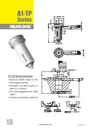
This <strong>Heatlock</strong> series, below, is currently being replaced by the A1-series of nozzles.<br />
Before you design check availability, stock is gradually decreased.<br />
Spare parts will be available until at least end of 2007 (apart form NPT1 bodies)<br />
Check list / Checklista<br />
Manifold assembly<br />
Check the following before the manifold is finally assembled (see<br />
overview on 4.1.8):<br />
1. Adjust all the ceramics, insulation for each bushing so that<br />
they are all at the same level as Plan ”B”.<br />
2. Put in the bushings and check that the bushings / torpedoes<br />
rear plane is at the same height, 0,01 mm, according to the<br />
measurement level “C”. Use three measuring points in each<br />
bushing.<br />
3. Assemble the ceramic KEM03001017 with the support<br />
DSP0353010, measure the total height (approx.24mm). Measure<br />
and reduce this height by the pre-bored depth of the<br />
ceramic in the manifold, (approx. 2 mm) and the measured<br />
distance between plane “C” and plane “B” (approx. 23 or 28<br />
mm depending on the bushing), the remaining 7 or 2 mm is<br />
countersunk in the form plate. It is important that the manifold<br />
is at the same level as the bushings and don’t have too much<br />
play or “roll” under the central support.<br />
4. If the manifold is to be bolted check that the shape of the hole<br />
in the manifold matches the hole shape in the cavity plate.<br />
5. Assemble the back support KE02500305 with the support<br />
DSP0300306 / DSP0300312, make sure that the ceramic<br />
reaches the bottom of the support. Measure and check the<br />
height of all the units. If there are any discrepancies, adjust all<br />
to the same height within 0.005 mm, work with the underside<br />
of the support. Fix this with dowel DW03X12 in the pre-bored<br />
holes in the manifold. Correct here for the air gap which there<br />
shall be in cold condition to allow for heat expansion according<br />
to table 1. plane “D”.<br />
6. Put the manifold on the bushings, which is centred using the<br />
ceramic center support KEM03001017. Torsion fixing is done<br />
with the help of dowels which are placed in the pre-milled slot<br />
in the manifold. This is done without the O-rings mounted.<br />
7. Tighten the manifold with the screws provided if the manifold<br />
is to be bolted, check that all the cables are free.<br />
8. Check the level of the upper part of the rear support plane “D”,<br />
they shall all be within 0.005 mm.<br />
9. Take off the manifold, assemble all the O-rings, re-assemble<br />
and check that there are no trapped cables or cables laying<br />
against the manifold.<br />
10. Check that the manifold is back at the right level/height from<br />
the measurement level “D”. If the manifold isn’t fixed the fixing<br />
plate is mounted and tightened so that the O-rings are pressed<br />
together before the control is carried out. Heat up to running<br />
temperature before the clamp plate is removed for the final<br />
check.<br />
Bench testing is important. It proves the electrics and wiring. The<br />
more areas that you know are working 100% the better.<br />
according to item 5 above, specify the Airgap:.........<br />
Kontrollera följande innan varmkanalsbalken monteras slutgiltigt<br />
(se översikten på 4.1.8):<br />
1. Justera in all keramik , isolering för varje bussning så att samtliga<br />
ligger på samma nivå som Plan ”B”.<br />
2. Sätt dit bussningarna och kontrollera att bussningarna / torpedernas<br />
bakre plan ligger inom samma höjd, 0,01 mm, enligt<br />
mätvärdesnivå “C”. Använd tre mätpukter på respektive bussning.<br />
3. Sätt ihop keramiken KEM03001017 med stödet DSP0353010,<br />
mät upp totalhöjden, (ca.24mm). Mät upp och minska denna<br />
höjd med det förborrade djupet för keramiken i varmkanalbalken,<br />
( ca. 2 mm) samt det uppmätta måttet mellan plan “C”<br />
och plan “B” (ca. 23 eller 28 mm beroende på bussning), återstående<br />
ca 7 eller 2 mm försänkes i formplattan. Viktigt är att<br />
varmkanalbalken ligger i samma nivå som bussningarna och<br />
inte glappar eller “rullar” under centrumstödet.<br />
4. Om varmkanalbalken skall bultas fast kontrollera då att hålbilden<br />
i balken överenstämmer med hålbilden i formplattan.<br />
5. Sätt ihop det bakre keramiken KE02500305 med stödet<br />
DSP0300306 / DSP0300312, försäkra Dig om att keramiken<br />
bottnar i stödet. Mät upp och kontrollera höjden på samtliga<br />
enheter. Om eventuell avikelse förekommer , slipa in samtliga<br />
till samma höjd, inom 0.005mm, slipa på stödets undersida.<br />
Fixera sedan denna enhet med stift DW03X12 i de förborrade<br />
hålen i balken. Korrigera även här luftspalten som skall råda i<br />
kallt tillstånd som krävs för värmeexpandering i enlighet med<br />
tabell 1. Plan “D”.<br />
6. Lägg varmkanalbalken på ingötsbussningarna, som centreras<br />
i centrumstödet KEM03001017. Vridfixeringen görs med hjälp<br />
av en Cylindrisk Pinne som placeras i det förfrästa spåret i balken.<br />
Detta görs utan att O-ringarna är monterade.<br />
7. Skruva fast varmkanalbalken med avsedda skruvar om balken<br />
skall bultas fast, kontrollera även att samtliga kablar är fria.<br />
8. Kontrollera här nivån på de bakre stödens ovansida -plan “D”,<br />
samtliga skall nu ligga inom 0.005 mm.<br />
9. Ta av balken montera samtliga O-ringar, återmontera och kontrollera<br />
att det inte finns några ledningar i kläm eller som ligger<br />
an mot varmkanalbalken.<br />
10. Kontrollera att varmkanalbalken är tillbaka till rätt nivå / höjd<br />
från mätvärdesnivå “D”. Om varmkanalbalken inte är fastskruvad<br />
monteras fästplattan och dras fast så att O-ringarna<br />
pressas samman innan denna kontroll genomförs. Värm upp<br />
systemet till drifttemperatur innan fästplattan tas bort för den<br />
sista kontrollen.<br />
Bänkprovet är viktigt. Det visar om de elektriska komponenterna<br />
och ledningsdragningen fungerar. Ju fler delar du vet fungerar till<br />
100 %, desto bättre.<br />
Enligt punkt 5 ovan, ange luftspalten:.........<br />
Controlled by / kontrollerad av:<br />
Company / Företag:<br />
Name / Namn:<br />
Address / Adress:<br />
Date / Datum:<br />
Project No. / Projektnr.<br />
At eventual complaint, this form shall be filled in<br />
and signed. Attach this form to the complaint.<br />
Vid eventuell reklamation skall denna sida vara<br />
ifylld och signerad samt bifogad till oss.<br />
4.1.12 Date: 031002, © LKM <strong>Heatlock</strong> Co Ltd