Heatlock ESB2, Electric Sprue Bushing
Heatlock ESB2, Electric Sprue Bushing
Heatlock ESB2, Electric Sprue Bushing

You also want an ePaper? Increase the reach of your titles
YUMPU automatically turns print PDFs into web optimized ePapers that Google loves.
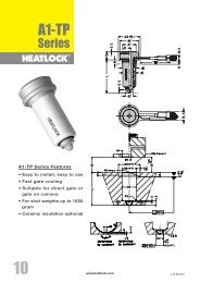
This <strong>Heatlock</strong> series, below, is currently being replaced by the A1-series of nozzles.<br />
Before you design check availability, stock is gradually decreased.<br />
Spare parts will be available until at least end of 2007 (apart form NPT1 bodies)<br />
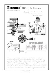
Manifold assembly<br />
Assembly Instruction / Monteringsanvisning<br />
Check the following before the manifold is finally assembled (see<br />
overview on the left side):<br />
Kontrollera följande innan varmkanalsbalken monteras slutgiltigt (se<br />
översikten på vänster sida):<br />
1. Adjust all the ceramics, insulation for each bushing so that they<br />
are all at the same level as Plan ”B”.<br />
2. Put in the bushings and check that the bushings / torpedoes rear<br />
plane is at the same height, 0,01 mm, according to the measurement<br />
level “C”. Use three measuring points in each bushing.<br />
3. Assemble the ceramic KEM03001017 with the support<br />
DSP0353010, measure the total height (approx.24mm). Measure<br />
and reduce this height by the pre-bored depth of the ceramic in<br />
the manifold, (approx. 2 mm) and the measured distance between<br />
plane “C” and plane “B” (approx. 23 or 28 mm depending on<br />
the bushing), the remaining 7 or 2 mm is countersunk in the form<br />
plate. It is important that the manifold is at the same level as the<br />
bushings and don’t have too much play or “roll” under the central<br />
support.<br />
4. If the manifold is to be bolted check that the shape of the hole in<br />
the manifold matches the hole shape in the cavity plate.<br />
5. Assemble the back support KE02500305 with the support<br />
DSP0300306 / DSP0300312, make sure that the ceramic reaches<br />
the bottom of the support. Measure and check the height of all the<br />
units. If there are any discrepancies, adjust all to the same height<br />
within 0.005 mm, work with the underside of the support. Fix this<br />
with dowel DW03X12 in the pre-bored holes in the manifold. Correct<br />
here for the air gap which there shall be in cold condition to<br />
allow for heat expansion according to table 1. plane “D”.<br />
6. Put the manifold on the bushings, which is centred using the ceramic<br />
center support KEM03001017. Torsion fixing is done with<br />
the help of dowels which are placed in the pre-milled slot in the<br />
manifold. This is done without the O-rings mounted.<br />
7. Tighten the manifold with the screws provided if the manifold is to<br />
be bolted, check that all the cables are free.<br />
8. Check the level of the upper part of the rear support plane “D”,<br />
they shall all be within 0.005 mm.<br />
9. Take off the manifold, assemble all the O-rings, re-assemble and<br />
check that there are no trapped cables or cables laying against<br />
the manifold.<br />
10. Check that the manifold is back at the right level/height from the<br />
measurement level “D”. If the manifold isn’t fixed the fixing plate<br />
is mounted and tightened so that the O-rings are pressed together<br />
before the control is carried out. Heat up to running temperature<br />
before the clamp plate is removed for the final check.<br />
Bench testing is important. It proves the electrics and wiring.<br />
The more areas that you know are working 100% the<br />
better.<br />
31 1 HEATMANPROOF Proof of drawing in order to start<br />
30 1 HEATMANDOC Documentation of the Hot-Runner System<br />
20 2 <strong>ESB2</strong>046102 <strong>Sprue</strong> Bush, Series 2, L=46 mm<br />
15 1 DW08X40 Dowell Ø8x40<br />
14 1 TC00040180 Thermocouple, L=12<br />
13 14 MF6S08X008 Screw M5x8<br />
12 2 DW03X12 Dowell Ø3x12<br />
11 2 DSP0300306 Back Spacer<br />
10 2 KE02500305 Ceramic Back Support<br />
9 1 CS06020 Screw M6x20<br />
8 1 DSP0353010 Center Location spacer<br />
7 1 KEM03001017 Ceramic Center Spacer<br />
6 1 DSPP503107 Purge Guard<br />
5 1 DSP4503008 Feedbush<br />
4 4 MHWIRE050 Wire<br />
3 4 MHCONN001 Ceramic Connector<br />
2 2 MHI02400 Tubular Heater<br />
1 1 MI2400004608 Standard Manifold, CC=240mm, Feed=Ø8 mm<br />
Item Qty Art. Nr. Description<br />
1. Justera in all keramik , isolering för varje bussning så att samtliga<br />
ligger på samma nivå som Plan ”B”.<br />
2. Sätt dit bussningarna och kontrollera att bussningarna / torpedernas<br />
bakre plan ligger inom samma höjd, 0,01 mm, enligt mätvärdesnivå<br />
“C”. Använd tre mätpukter på respektive bussning.<br />
3. Sätt ihop keramiken KEM03001017 med stödet DSP0353010, mät<br />
upp totalhöjden, (ca.24mm). Mät upp och minska denna höjd med<br />
det förborrade djupet för keramiken i varmkanalbalken, ( ca. 2<br />
mm) samt det uppmätta måttet mellan plan “C” och plan “B” (ca.<br />
23 eller 28 mm beroende på bussning), återstående ca 7 eller 2<br />
mm försänkes i formplattan. Viktigt är att varmkanalbalken ligger i<br />
samma nivå som bussningarna och inte glappar eller “rullar” under<br />
centrumstödet.<br />
4. Om varmkanalbalken skall bultas fast kontrollera då att hålbilden i<br />
balken överenstämmer med hålbilden i formplattan.<br />
5. Sätt ihop det bakre keramiken KE02500305 med stödet<br />
DSP0300306 / DSP0300312, försäkra Dig om att keramiken bottnar<br />
i stödet. Mät upp och kontrollera höjden på samtliga enheter.<br />
Om eventuell avikelse förekommer , slipa in samtliga till samma<br />
höjd, inom 0.005mm, slipa på stödets undersida. Fixera sedan<br />
denna enhet med stift DW03X12 i de förborrade hålen i balken.<br />
Korrigera även här luftspalten som skall råda i kallt tillstånd som<br />
krävs för värmeexpandering i enlighet med tabell 1. Plan “D”.<br />
6. Lägg varmkanalbalken på ingötsbussningarna, som centreras i<br />
centrumstödet KEM03001017. Vridfixeringen görs med hjälp av en<br />
Cylindrisk Pinne som placeras i det förfrästa spåret i balken. Detta<br />
görs utan att O-ringarna är monterade.<br />
7. Skruva fast varmkanalbalken med avsedda skruvar om balken<br />
skall bultas fast, kontrollera även att samtliga kablar är fria.<br />
8. Kontrollera här nivån på de bakre stödens ovansida -plan “D”,<br />
samtliga skall nu ligga inom 0.005 mm.<br />
9. Ta av balken montera samtliga O-ringar, återmontera och kontrollera<br />
att det inte finns några ledningar i kläm eller som ligger an mot<br />
varmkanalbalken.<br />
10. Kontrollera att varmkanalbalken är tillbaka till rätt nivå / höjd från<br />
mätvärdesnivå “D”. Om varmkanalbalken inte är fastskruvad monteras<br />
fästplattan och dras fast så att O-ringarna pressas samman<br />
innan denna kontroll genomförs. Värm upp systemet till drifttemperatur<br />
innan fästplattan tas bort för den sista kontrollen.<br />
Bänkprovet är viktigt. Det visar om de elektriska komponenterna<br />
och ledningsdragningen fungerar. Ju fler delar du vet<br />
fungerar till 100 %, desto bättre.<br />
Table 1 / tabell 1<br />
Heat expansion<br />
°C T=36 T=46 T=56<br />
200 0.08 0.10 0.13<br />
250 0.10 0.13 0.16<br />
300 0.12 0.16 0.20<br />
350 0.14 0.18 0.23<br />
Date: 031002, © LKM <strong>Heatlock</strong> Co Ltd<br />
4.1.11