Heatlock ESB2, Electric Sprue Bushing
Heatlock ESB2, Electric Sprue Bushing
Heatlock ESB2, Electric Sprue Bushing

You also want an ePaper? Increase the reach of your titles
YUMPU automatically turns print PDFs into web optimized ePapers that Google loves.
This <strong>Heatlock</strong> series, below, is currently being replaced by the A1-series of nozzles.<br />
Before you design check availability, stock is gradually decreased.<br />
Spare parts will be available until at least end of 2007 (apart form NPT1 bodies)<br />
NPT1<br />
”L”<br />
mm<br />
Single-cav.<br />
Part No.<br />
Multi-cav.*<br />
Total volume<br />
of feed<br />
channel in<br />
mm 3<br />
26 NPT1026411 NPT1026412 558<br />
Ø30 f8<br />
36 NPT1036411 NPT1036412 683<br />
Ø29<br />
Ø22<br />
Ø4<br />
23 +0.01<br />
0<br />
46 NPT1046411 NPT1046412 809<br />
86 – NPT1086412 1311<br />
106 – NPT1106412 1563<br />
* with O-ring 608<br />
+0.03<br />
L -0<br />
8 15,5<br />
22h6<br />
13,5<br />
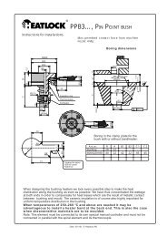
Can be controlled with various types of temperature controllers intended for<br />
hot runner systems with 220/240 V using thermocouple of type Fe-CuNi.<br />
Recommended for the following maximum shot weights:<br />
Low-viscosity plastic (PS,PE,PP)<br />
150g<br />
15<br />
Ø0,2<br />
Med.-viscosity plastic (ABS,SAN, PA,POM)<br />
High-viscosity plastic (PC,PMMA, Noryl, Filled material)<br />
80g<br />
20g<br />
Max gate Ø2.5 mm.<br />
Length expansion at: °C=”L”+X,xx<br />
°C 26 36 46 86 106<br />
200 0,03 0,04 0,05 0,10 0,12<br />
15,5<br />
250 0,04 0,05 0,06 0,12 0,15<br />
300 0,04 0,06 0,08 0,14 0,18<br />
350 0,05 0,07 0,09 0,17 0,21<br />
To ensure minimum vestige on the part, measure the actual "L" measurement<br />
on each bush, add the length expansion according to the table to get<br />
the hole depth ("L"+X,xx) to be drilled in the cavity plate.<br />
Före inbyggnad, mät upp bussningens nominella "L"-mått, lägg därefter till<br />
längdutvidgningen så att bussningens spets ligger exakt vid intagspunkten i<br />
uppvärmt tillstånd.<br />
Ø17<br />
max 1.5<br />
8 15.5 8<br />
R0.4 max<br />
Ø6<br />
30H7<br />
15 +0.01<br />
-0<br />
2.5<br />
8 +0.01<br />
L<br />
Ø22H7<br />
Ø0.01<br />
R4<br />
30.0° 60.0°<br />
0.2<br />
max Ø2.5<br />
more<br />
2.08.2 Date: 031002, © LKM <strong>Heatlock</strong> Co Ltd