Heatlock ESB2, Electric Sprue Bushing
Heatlock ESB2, Electric Sprue Bushing
Heatlock ESB2, Electric Sprue Bushing

Create successful ePaper yourself
Turn your PDF publications into a flip-book with our unique Google optimized e-Paper software.
R3<br />
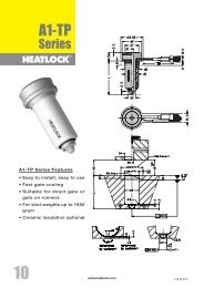
This <strong>Heatlock</strong> series, below, is currently being replaced by the A1-series of nozzles.<br />
Before you design check availability, stock is gradually decreased.<br />
Spare parts will be available until at least end of 2007 (apart form NPT1 bodies)<br />
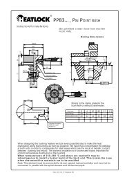
PPB1<br />
0.5<br />
Ø4<br />
Ø30 f8<br />
Ø20<br />
”L”<br />
mm<br />
Single-cav.<br />
Part No.<br />
Multi-cav.*<br />
Total volume<br />
of feed<br />
channel in<br />
mm 3<br />
26 PPB1026101 PPB1026102 560<br />
23 +0.01<br />
0<br />
36 PPB1036101 PPB1036102 686<br />
46 PPB1046101 PPB1046102 812<br />
86 PPB1086101 PPB1086102 1314<br />
L +0.1<br />
-0.02<br />
8<br />
Ø20<br />
10.8<br />
106 PPB1106101 PPB1106102 1565<br />
* with O-ring 500 / 608<br />
Ø1.5<br />
Can be controlled with various types of temperature controllers intended for<br />
hot runner systems with 220/240 V using thermocouple of type Fe-CuNi.<br />
4<br />
Ø8 h6<br />
Recommended for the following maximum shot weights:<br />
Low-viscosity plastic (PS,PE,PP)<br />
200g<br />
Med.-viscosity plastic (ABS,SAN, PA,POM)<br />
100g<br />
High-viscosity plastic (PC,PMMA, Noryl, Filled material)<br />
30g<br />
15.5<br />
Gate diameter is Ø0.8 mm on delivery, can be reamed up to Ø1.5 mm if<br />
needed. Please, look at page 9 regarding gate diameter.<br />
Length expansion at: °C=”L”+X,xx<br />
°C 26 36 46 86 106<br />
Ø16<br />
200 0,06 0,08 0,11 0,20 0,24<br />
250 0,08 0,10 0,13 0,25 0,31<br />
300 0,09 0,12 0,16 0,30 0,37<br />
350 0,10 0,14 0,19 0,35 0,43<br />
8<br />
To ensure minimum vestige on the part, measure the actual "L" measurement<br />
on each bush, add the length expansion according to the table to get<br />
the hole depth ("L"+X,xx) to be drilled in the cavity plate.<br />
23.5<br />
R0.4 max Ø6<br />
2.5<br />
Före inbyggnad, mät upp bussningens nominella "L"-mått, lägg därefter till<br />
längdutvidgningen så att bussningens spets ligger exakt vid intagspunkten i<br />
uppvärmt tillstånd.<br />
1.5<br />
L<br />
23 +0.01<br />
-0<br />
25°<br />
Ø24<br />
Ø8 H7<br />
Ø0.01<br />
Ø30 H7<br />
max 1.5<br />
R3<br />
0.2<br />
Ø0.8<br />
more<br />
2.05.2 Date: 030930, © LKM <strong>Heatlock</strong> Co Ltd