Heatlock ESB2, Electric Sprue Bushing
Heatlock ESB2, Electric Sprue Bushing
Heatlock ESB2, Electric Sprue Bushing

You also want an ePaper? Increase the reach of your titles
YUMPU automatically turns print PDFs into web optimized ePapers that Google loves.
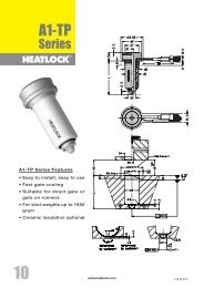
This <strong>Heatlock</strong> series, below, is currently being replaced by the A1-series of nozzles.<br />
Before you design check availability, stock is gradually decreased.<br />
Spare parts will be available until at least end of 2007 (apart form NPT1 bodies)<br />
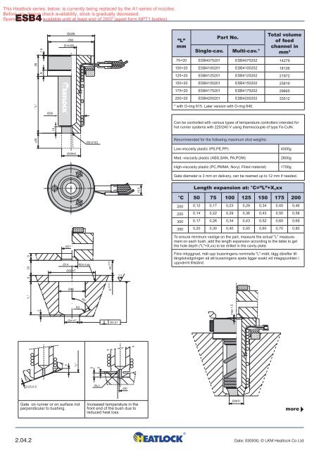
ESB4<br />
+20 "L" 28<br />
8 1.5<br />
Ø36<br />
10<br />
Ø62f8<br />
Ø60<br />
Ø14/(B)<br />
Ø3-3°(C)<br />
”L”<br />
mm<br />
Single-cav.<br />
Part No.<br />
Multi-cav.*<br />
Total volume<br />
of feed<br />
channel in<br />
mm 3<br />
75+20 ESB4075201 ESB4075202 14279<br />
100+20 ESB4100201 ESB4100202 18126<br />
125+20 ESB4125201 ESB4125202 21972<br />
150+20 ESB4150201 ESB4150202 25819<br />
175+20 ESB4175201 ESB4175202 29665<br />
200+20 ESB4200201 ESB4200202 33512<br />
* with O-ring 615. Later version with O-ring 640.<br />
Can be controlled with various types of temperature controllers intended for<br />
hot runner systems with 220/240 V using thermocouple of type Fe-CuNi.<br />
Recommended for the following maximum shot weights:<br />
Ø25h6<br />
Low-viscosity plastic (PS,PE,PP)<br />
Med.-viscosity plastic (ABS,SAN, PA,POM)<br />
4500g<br />
2800g<br />
High-viscosity plastic (PC,PMMA, Noryl, Filled material)<br />
1700g<br />
Gate diameter is 3 mm on delivery, can be reamed up to 12 mm if needed.<br />
15.5<br />
Length expansion at: °C=”L”+X,xx<br />
°C 50 75 100 125 150 175 200<br />
200 0,12 0,17 0,23 0,29 0,34 0,40 0,46<br />
250 0,14 0,22 0,29 0,36 0,43 0,50 0,58<br />
300 0,17 0,26 0,34 0,43 0,52 0,60 0,69<br />
350 0,20 0,30 0,40 0,50 0,60 0,70 0,80<br />
Ø27<br />
To ensure minimum vestige on the part, measure the actual "L" measurement<br />
on each bush, add the length expansion according to the table to get<br />
the hole depth ("L"+X,xx) to be drilled in the cavity plate.<br />
9<br />
8<br />
Ø14<br />
R04 max<br />
+0.01<br />
-0<br />
Före inbyggnad, mät upp bussningens nominella "L"-mått, lägg därefter till<br />
längdutvidgningen så att bussningens spets ligger exakt vid intagspunkten i<br />
uppvärmt tillstånd.<br />
20<br />
Ø62H7<br />
20<br />
2.5<br />
Ø40<br />
"L"<br />
+0.01<br />
8<br />
65°<br />
2<br />
R3<br />
max 1,5<br />
ØA H7<br />
Ø0.01<br />
5<br />
2<br />
5<br />
"L"<br />
0.25-0.5<br />
R=1<br />
ØD<br />
Gate on runner or on surface not<br />
perpendicular to bushing.<br />
Ø(D+4)<br />
Increased temperature in the<br />
front end of the bush due to<br />
reduced heat loss.<br />
ØAH7<br />
more<br />
2.04.2 Date: 030930, © LKM <strong>Heatlock</strong> Co Ltd