Heatlock ESB2, Electric Sprue Bushing
Heatlock ESB2, Electric Sprue Bushing
Heatlock ESB2, Electric Sprue Bushing

Create successful ePaper yourself
Turn your PDF publications into a flip-book with our unique Google optimized e-Paper software.
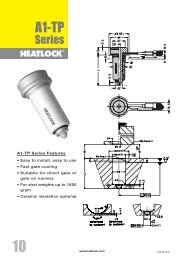
This <strong>Heatlock</strong> series, below, is currently being replaced by the A1-series of nozzles.<br />
Before you design check availability, stock is gradually decreased.<br />
Spare parts will be available until at least end of 2007 (apart form NPT1 bodies)<br />
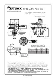
NPT2…, NEEDLE POINT TOPLESS<br />
Instructions for installations.<br />
Max permitted contact force from machine nozzle: 4T<br />
Single-cavity<br />
assembly<br />
Ø50 f8<br />
Multi-cavity<br />
assembly<br />
Boring dimensions<br />
Ø48f8<br />
Ø35<br />
Ø23<br />
Ø6<br />
32<br />
"L"+X,xx 8<br />
3<br />
Ø35<br />
40<br />
"L"<br />
4<br />
8<br />
Ø27 h6<br />
21<br />
• •<br />
•<br />
•<br />
45<br />
Ceramic insulation<br />
Thermocouple<br />
Coilheater<br />
Front cap<br />
10.5 9<br />
28 +0<br />
-0.05<br />
7,6<br />
Ø8,9<br />
Ø24 R04 max<br />
Ø50 H7<br />
Ø27 H7<br />
R4<br />
60°<br />
+0.01<br />
-0<br />
20<br />
+0.01<br />
8<br />
Ø0,01<br />
2,5<br />
Ø0,5<br />
30°<br />
0,2<br />
1<br />
C2<br />
Boring in the clamp plate for the bush with or without<br />
bandheater:<br />
R<br />
R5<br />
R5<br />
A<br />
R5<br />
B2<br />
B1<br />
Utgång för kabel<br />
Slot for cable<br />
Kabelnut<br />
Art. nr. R A B1 B2 C1 C2<br />
<strong>Bushing</strong> 28 20 - - - -<br />
B047015315 36 22 15 22 45 45<br />
B048020180 36 22 36 22 70 40<br />
C1<br />
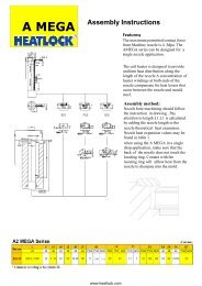
Colour code for thermocouple wires.<br />
Black (red) wire + (Iron) White (blue) wire —.<br />
The connector sleeve of the thermocouple has a max. temperature resistance of 240 °C.<br />
When temperatures of 250–260 °C and above are needed it may be advantageous to install a heater band at the<br />
back end. This is also the case when shearsensitive materials are to be moulded.<br />
Length of the bushing.<br />
To ensure minimum vestige on the part.<br />
Measure the actual “L” measurement on each bush, add the length<br />
expansion according to the adjacent table to get the hole depth<br />
(“L”+X,xx) to be drilled in the cavity plate<br />
°C="L"+X,xx<br />
°C 26 46 66<br />
200 +0,10 +0,17 +0,23<br />
250 +0,13 +0,21 +0,30<br />
300 +0,16 +0,26 +0,36<br />
350 +0,19 +0,30 +0,42<br />
Date: 001101, © <strong>Heatlock</strong> AB<br />
© LKM <strong>Heatlock</strong> Co Ltd<br />
Appendix – 31