8 7 This <strong>Heatlock</strong> series, below, is currently being replaced by the A1-series of nozzles. Before you design check availability, stock is gradually decreased. Spare parts will be available until at least end of 2007 (apart form NPT1 bodies) Montering av balk / Manifold Assembly / Einbau des Verteilerbalkens svenska Kontrollera följande innan varmkanalsbalken monteras slutgiltigt (se översikten på vänster sida): 1. Justera in all keramik , isolering för varje bussning så att samtliga ligger på samma nivå som Plan ”B”. 2. Sätt dit bussningarna och kontrollera att bussningarna / torpedernas bakre plan ligger inom samm höjd, 0,01 mm, enligt mätvärdesnivå “C”. Använd tre mätpukter på respektive bussning. 3. Sätt ihop keramiken KEM03001017 med stödet DSP0353010, mät upp totalhöjden, (ca.24mm). Mät upp och minska denna höjd med det förborrade djupet för keramiken i varmkanalbalken, ( ca. 2 mm) samt det uppmätta måttet mellan plan “C” och plan “B” (ca. 15,5 eller 20 mm beroende på bussning), återstående ca 6,5 eller 2 mm försänkes i formplattan. Viktigt är att varmkanalbalken ligger i samma nivå som bussningarna och inte glappar eller “rullar” under centrumstödet. 4. Om varmkanalbalken skall bultas fast kontrollera då att hålbilden i balken överenstämmer med hålbilden i formplattan. 5. Sätt ihop det bakre keramiken KE02500305 med stödet DSP0300306 / DSP0300312, försäkra Dig om att keramiken bottnar i stödet. Mät upp och kontrollera höjden på samtliga enheter. Om eventuell avikelse förekommer , slipa in samtliga till samma höjd, inom 0.005mm, slipa på stödets undersida. Fixera sedan denna enhet med stift DW03X12 i de förborrade hålen i balken. Korrigera även här luftspalten som skall råda i kallt tillstånd som krävs för värmeexpandering i enlighet med tabell 1. Plan “D”. 6. Lägg varmkanalbalken på ingötsbussningarna, som centreras i centrumstödet KEM03001017. Vridfixeringen görs med hjälp av en Cylindrisk Pinne som placeras i det förfrästa spåret i balken. Detta görs utan att O-ringarna är monterade. 7. Skruva fast varmkanalbalken med avsedda skruvar om balken skall bultas fast, kontrollera även att samtliga kablar är fria. 8. Kontrollera här nivån på de bakre stödens ovansida -plan “D”, samtliga skall nu ligga inom 0.005 mm. 9. Ta av balken montera samtliga O-ringar, återmontera och kontrollera att det inte finns några ledningar i kläm eller som ligger an mot varmkanalbalken. 10. Kontrollera att varmkanalbalken är tillbaka till rätt nivå / höjd från mätvärdesnivå “D”. Om varmkanalbalken inte är fastskruvad monteras fästplattan och dras fast så att O-ringarna pressas samman innan denna kontroll genomförs. Värm upp systemet till drifttemperatur innan fästplattan tas bort för den sista kontrollen. NPT1 / NPT1-Xtnd Bänkprovet är viktigt. Det visar om de elektriska komponenterna och ledningsdragningen fungerar. Ju fler delar du vet fungerar till 100 %, desto bättre. english Check the following before the manifold is finally assembled (see overview on the left side): 1. Adjust all the ceramics, insulation for each bushing so that they are all at the same level as Plan ”B”. 2. Put in the bushings and check that the bushings / torpedoes rear plane is at the same height, 0,01 mm, according to the measurement level “C”. Use three measuring points in each bushing. 3. Assemble the ceramic KEM03001017 with the support DSP0353010, measure the total height (approx.24mm). Measure and reduce this height by the pre-bored depth of the ceramic in the manifold, (approx. 2 mm) and the measured distance between plane “C” and plane “B” (approx. 15,5 or 20 mm depending on the bushing), the remaining 6,5 or 2 mm is countersunk in the form plate. It is important that the manifold is at the same level as the bushings and donʼt have too much play or “roll” under the central support. 4. If the manifold is to be bolted check that the shape of the hole in the manifold matches the hole shape in the cavity plate. 5. Assemble the back support KE02500305 with the support DSP0300306 / DSP0300312, make sure that the ceramic reaches the bottom of the support. Measure and check the height of all the units. If there are any discrepancies, adjust all to the same height within 0.005 mm, work with the underside of the support. Fix this with dowel DW03X12 in the pre-bored holes in the manifold. Correct here for the air gap which there shall be in cold condition to allow for heat expansion according to table 1. plane “D”. 6. Put the manifold on the bushings, which is centred using the ceramic center support KEM03001017. Torsion fixing is done with the help of dowels which are placed in the pre-milled slot in the manifold. This is done without the O-rings mounted. 7. Tighten the manifold with the screws provided if the manifold is to be bolted, check that all the cables are free. 8. Check the level of the upper part of the rear support plane “D”, they shall all be within 0.005 mm. 9. Take off the manifold, assemble all the O-rings, re-assemble and check that there are no trapped cables or cables laying against the manifold. 10. Check that the manifold is back at the right level/height from the measurement level “D”. If the manifold isnʼt fixed the fixing plate is mounted and tightened so that the O-rings are pressed together before the control is carried out. Heat up to running temperature before the clamp plate is removed for the final check. Bench testing is important. It proves the electrics and wiring. The more areas that you know are working 100% the better. deutsch Vor dem endgültigen Einbau der Heißkanalplatte muss Folgendes beachtet werden (siehe links): 6 Art. Nr: CAI-NPT1 Rev:01 "D" "C" "B" "Air gap, look at Table 1 36/46/56 23/28 +0.01 0 10 12 11 5 6 22 Ø32 Ø35 H7 g6 2/7 35 1 7 8 9 1. Justieren Sie die keramische Zentrierung, die Isolierung jeder Düse so, dass sämtliche auf der gleichen Ebene, wie in der Abb. unter ”B” angegeben, liegen. 2. Bringen Sie die Düsen an und kontrollieren Sie, dass der hintere Teil der Düsen/Torpedos innerhalb der gleichen Höhe , 0,01 mm, laut Messwertstufe ”C”, liegt. Bedienen Sie sich dreier Messpunkte an der entsprechenden Düse. 3. Einbau der keramischen Zentrierung KEM03001017 mit Zentrierhülse DSP0353010 und Messen der Gesamthöhe (ca 24 mm): Messen und vermindern Sie die Höhe mit den vorgebohrten Durchgängen für die keramische Zentrierhülse an der Heißkanalplatte, (ca 2 mm) sowie den Messwert zwischen Stufe ”C” und ”B” (ca 15,5 oder 20 mm je nach Wahl der Düse). Die verbleibenden ca 6,5 oder 2 mm werden in die Formplatte versenkt. Wichtig dabei ist, dass die Heißkanalplatte auf gleicher Ebene wie die Düsen liegt und nicht schleudern oder schlingern darf. 4. Wenn die Heißkanalplatte verbolzt werden soll, ist darauf zu achten, dass die Durchgangs- und Gewindebohrungen im Verteilerbalken mit der der Formplatte genau übereinstimmen. 5. Verbinden Sie den hinteren keramischen Stützring KEM02500305 mit der hinteren Hülse DSP0300306/ DSP0300312, vergewissern Sie sich, dass Sie richtig eingesetzt ist. Vermessen und kontrollieren Sie die Höhen an sämtlichen Einheiten. Sollten eventuelle Abweichungen vorkommen, korriegieren Sie diese durch Abschleifen auf die gleiche Höhe, innerhalb einer Toleranz von 0.005 mm, schleifen Sie die Unterseite der Hülse. Fixieren Sie anschliebend diese Einheit mit dem Stift DW03X12 in die vorgebohrten Durchgänge am Verteiler. Korrigieren Sie auch hier den Luftspalt im kalten Zustand zum Zwecke der Wärmeausdehnung. Vgl. Tabelle 1. ”D”. 6. Legen Sie die Heißkanalplatte auf die Eingussdüsen, die in der keramischen Zentrierung KEM03001017 zentriert werden. Die Drehfixierung geschieht mit Hilfe eines zylindrischen Stiftes, der an der vorgefrästen Nute am Verteiler angebracht wird. Dieser Vorgang wird ohne das Vorhandensein von O-Ringen durchgeführt. 7. Schrauben Sie den Verteilerbalken, falls die Platte verschraubt werden soll, mit den vorgesehenen Schrauben fest. Überprüfen Sie, dass sämtliche Leitungen freigelegt sind. 8. Kontrollieren Sie die Werte der Oberseite der hinteren keramischen Stützscheibe (vgl. ”D”). Die Toleranzgrenze von 0,005 mm darf nicht überschritten werden. 9. Nehmen Sie den Verteiler ab, legen Sie sämtliche 0-Ringe an, bringen Sie den Verteiler wieder an und versichern Sie sich, dass keine Leitungen eingeklemmt sind oder an der Heißkanalplatte anliegen. 10. Überprüfen Sie, dass sich die Heißkanalplatte, vom Ausgangswert ”D” aus, wieder auf der richtigen Höhenstufe befindet. Falls die Heißkanalplatte noch nicht angeschraubt ist, wird die Befestigungsplatte montiert und fest angezogen, so dass die O-Ringe zusammengepresst werden, bevor die Prüfung durchgeführt wird. Erwärmen Sie das System auf Betriebstemperatur, bevor die Befestigungsplatte zur letzten Kontrolle entfernt wird. Eine Endabnahme ist notwendig und wichtig. Sie garantiert die Richtigkeit der Funktionen aller elektrischen Komponenten und Leitungen. Je mehr Sie sich von der 100%ige Funktionstauglichkeit der Teile überzeugen, desto erfolgreicher die Arbeit. Table 1 / tabell 1 / Tabelle 1 Heat expansion °C T = 3 6 T = 4 6 T = 5 6 200 0,08 0,10 0,13 250 0,10 0,13 0,16 300 0,12 0,16 0,20 350 0,14 0,18 0,23 13 14 15 20 fix bolts 15 min free space all around 31 1 HEATMANPROOF Proof of drawing in order to start 30 1 HEATMANDOC Documentation of the Hot-Runner System 20 2 <strong>ESB2</strong>046102 <strong>Sprue</strong> Bush, Series 2, L=46 mm 15 1 DW08X40 Dowell Ø8x40 14 1 TC00040180 Thermocouple, L=12 13 14 MF6S08X008 Screw M5x8 12 2 DW03X12 Dowell Ø3x12 11 2 DSP0300306 Back Spacer 10 2 KE02500305 Ceramic Back Support 9 1 CS06020 Screw M6x20 8 1 DSP0353010 Center Location spacer 7 1 KEM03001017 Ceramic Center Spacer 6 1 DSPP503107 Purge Guard 5 1 DSP4503008 Feedbush 4 4 MHWIRE050 Wire 3 4 MHCONN001 Ceramic Connector 2 2 MHI02400 Tubular Heater 1 1 MI2400004608 Standard Manifold, CC=240mm, Feed=Ø8 mm Item Qty Art. Nr. Description 2 3 4 © LKM <strong>Heatlock</strong> Co Ltd Appendix – 27
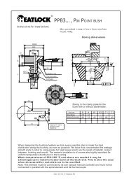
This <strong>Heatlock</strong> series, below, is currently being replaced by the A1-series of nozzles. Before you design check availability, stock is gradually decreased. Spare parts will be available until at least end of 2007 (apart form NPT1 bodies) Inbyggnad / Installations / Einb SE Anvisning för inbyggnad. Max. tillåten anläggningskraft från maskinmunstycke: 40 kN GB Instructions for installations. Max permitted contact force from machine nozzle: 40 kN DE Einbauanleitungen Höchstzulässige Anpreßkraft der Maschinendüse: 40 kN Enfacksmontering Single Cavity Assembly Einzelfachausführung Ø30 f8 Ø29 Ø22 Ø4 Flerfacksmontering Multi Cavity Assembly Mehrfachausführung 23 +0,01 -0 NPT1 Enfacksmontering Single Cavity Assembly Einzelfachausführung Ø30 f8 Ø4 Ø29 Flerfacksmontering Multi Cavity Assembly Mehrfachausführung 23 +0,01 -0 NPT1-Xtnd 15,5 8 • • 13 15,5 8 • • 13 +0,03 -0 L 15 22h6 • • Ø0,2 Keramisk isolerring Ceramic Insulation Keramischer Isolierung Termoelement Thermocouple Thermofühler Spiralelement Coilheater Heizkörper Styrhylsa Front cap Führungshülse +0,03 -0 L22h6 19 • • Ø0,2 Keramisk isolerring Ceramic Insulation Keramischer Isolierung Termoelement Thermocouple Thermofühler Spiralelement Coilheater Heizkörper Styrhylsa Front cap Führungshülse Håltagning i formen Boring in the clamp plate Bohrung in der Befestigungsplatte Håltagning i formen Boring in the clamp plate Bohrung in der Befestigungsplatte Ø17 Ø17 "L" 8 15,5 8 R04 max Ø6 30 H7 Ø22 H7 R4 +0,01 -0 15 8 +0,01 -0 Ø0,01 2,5 "L" 8 15,5 8 L-9 R04 max Ø6 30 H7 Ø22 H7 R4 60 +0,01 -0 15 8 +0,01 -0 2,5 Ø0,01 35 30,0 60,0 Ø2,5 0,2 Ø2,5 0,2 10 (20) Utgång för kabel Slot for cable Kabelnut SE GB Håltagning för bussning med eller utan ringelement Boring in the clamp plate for the bush with or without bandheater 37.5 DE Bohrung in der Befestigungsplatte für Düsen mit oder ohne Ringheizer R22.5 30 Art.Nr. 50 4xR10 B028013180 Appendix – 28 © LKM <strong>Heatlock</strong> Co Ltd
- Page 2 and 3:
This Heatlock series, below, is cur
- Page 4 and 5:
This Heatlock series, below, is cur
- Page 6 and 7:
This Heatlock series, below, is cur
- Page 8 and 9:
This Heatlock series, below, is cur
- Page 10 and 11:
This Heatlock series, below, is cur
- Page 12 and 13:
This Heatlock series, below, is cur
- Page 14 and 15:
This Heatlock series, below, is cur
- Page 16 and 17:
This Heatlock series, below, is cur
- Page 18 and 19:
This Heatlock series, below, is cur
- Page 20 and 21:
This Heatlock series, below, is cur
- Page 22 and 23:
This Heatlock series, below, is cur
- Page 24 and 25:
This Heatlock series, below, is cur
- Page 26 and 27:
This Heatlock series, below, is cur
- Page 28 and 29:
This Heatlock series, below, is cur
- Page 30 and 31:
This Heatlock series, below, is cur
- Page 32 and 33:
This Heatlock series, below, is cur
- Page 34 and 35:
This Heatlock series, below, is cur
- Page 36 and 37:
This Heatlock series, below, is cur
- Page 38 and 39:
This Heatlock series, below, is cur
- Page 40 and 41:
This Heatlock series, below, is cur
- Page 42 and 43:
This Heatlock series, below, is cur
- Page 44 and 45:
This Heatlock series, below, is cur
- Page 46 and 47:
This Heatlock series, below, is cur
- Page 48 and 49:
This Heatlock series, below, is cur
- Page 50 and 51:
This Heatlock series, below, is cur
- Page 52 and 53:
This Heatlock series, below, is cur
- Page 54 and 55:
This Heatlock series, below, is cur
- Page 56 and 57:
This Heatlock series, below, is cur
- Page 58 and 59:
This Heatlock series, below, is cur
- Page 60 and 61:
This Heatlock series, below, is cur
- Page 62 and 63:
This Heatlock series, below, is cur
- Page 64 and 65:
Cartridge Heaters This Heatlock ser
- Page 66 and 67:
Coilheater This Heatlock series, be
- Page 68 and 69:
Thermocouples This Heatlock series,
- Page 70 and 71:
This Heatlock series, below, is cur
- Page 72 and 73:
This Heatlock series, below, is cur
- Page 74 and 75:
This Heatlock series, below, is cur
- Page 76 and 77:
This Heatlock series, below, is cur
- Page 78 and 79:
This Heatlock series, below, is cur
- Page 80 and 81:
This Heatlock series, below, is cur
- Page 82 and 83:
This Heatlock series, below, is cur
- Page 84 and 85:
This Heatlock series, below, is cur
- Page 86 and 87:
This Heatlock series, below, is cur
- Page 88 and 89:
This Heatlock series, below, is cur
- Page 90 and 91:
This Heatlock series, below, is cur
- Page 92 and 93:
This Heatlock series, below, is cur
- Page 94 and 95:
This Heatlock series, below, is cur
- Page 96 and 97:
This Heatlock series, below, is cur
- Page 98 and 99:
This Heatlock series, below, is cur
- Page 100 and 101:
This Heatlock series, below, is cur
- Page 102 and 103:
This Heatlock series, below, is cur
- Page 104 and 105:
This Heatlock series, below, is cur
- Page 106 and 107:
This Heatlock series, below, is cur
- Page 108 and 109:
This Heatlock series, below, is cur
- Page 110 and 111:
This Heatlock series, below, is cur
- Page 112 and 113:
This Heatlock series, below, is cur
- Page 114 and 115:
This Heatlock series, below, is cur
- Page 116 and 117:
This Heatlock series, below, is cur
- Page 118 and 119:
This Heatlock series, below, is cur
- Page 120 and 121:
This Heatlock series, below, is cur
- Page 122 and 123: This Heatlock series, below, is cur
- Page 124 and 125: This Heatlock series, below, is cur
- Page 126 and 127: This Heatlock series, below, is cur
- Page 128 and 129: 34.5 7.5 This Heatlock series, belo
- Page 130 and 131: This Heatlock series, below, is cur
- Page 132 and 133: This Heatlock series, below, is cur
- Page 134 and 135: This Heatlock series, below, is cur
- Page 136 and 137: DIGITAL CONTROLLERS This Heatlock s
- Page 138 and 139: DIGITAL CONTROLLERS This Heatlock s
- Page 140 and 141: This Heatlock series, below, is cur
- Page 142 and 143: This Heatlock series, below, is cur
- Page 144 and 145: This Heatlock series, below, is cur
- Page 146 and 147: This Heatlock series, below, is cur
- Page 148 and 149: 8 7 This Heatlock series, below, is
- Page 150 and 151: This Heatlock series, below, is cur
- Page 152 and 153: This Heatlock series, below, is cur
- Page 154 and 155: This Heatlock series, below, is cur
- Page 156 and 157: This Heatlock series, below, is cur
- Page 158 and 159: This Heatlock series, below, is cur
- Page 160 and 161: This Heatlock series, below, is cur
- Page 162 and 163: This Heatlock series, below, is cur
- Page 164 and 165: This Heatlock series, below, is cur
- Page 166 and 167: This Heatlock series, below, is cur
- Page 168 and 169: This Heatlock series, below, is cur
- Page 170 and 171: This Heatlock series, below, is cur
- Page 174 and 175: This Heatlock series, below, is cur
- Page 176 and 177: This Heatlock series, below, is cur
- Page 178 and 179: This Heatlock series, below, is cur
- Page 180 and 181: This Heatlock series, below, is cur
- Page 182 and 183: 8 7 This Heatlock series, below, is
- Page 184 and 185: This Heatlock series, below, is cur
- Page 186 and 187: This Heatlock series, below, is cur