Heatlock ESB2, Electric Sprue Bushing
Heatlock ESB2, Electric Sprue Bushing
Heatlock ESB2, Electric Sprue Bushing

Create successful ePaper yourself
Turn your PDF publications into a flip-book with our unique Google optimized e-Paper software.
8<br />
7<br />
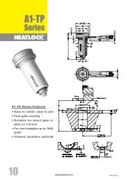
This <strong>Heatlock</strong> series, below, is currently being replaced by the A1-series of nozzles.<br />
Before you design check availability, stock is gradually decreased.<br />
Spare parts will be available until at least end of 2007 (apart form NPT1 bodies)<br />
Montering av balk / Manifold Assembly / Einbau des Verteilerbalkens<br />
svenska<br />
Kontrollera följande innan varmkanalsbalken monteras slutgiltigt (se översikten på vänster sida):<br />
1. Justera in all keramik , isolering för varje bussning så att samtliga ligger på samma nivå som Plan ”B”.<br />
2. Sätt dit bussningarna och kontrollera att bussningarna / torpedernas bakre plan ligger inom samm höjd, 0,01 mm,<br />
enligt mätvärdesnivå “C”. Använd tre mätpukter på respektive bussning.<br />
3. Sätt ihop keramiken KEM03001017 med stödet DSP0353010, mät upp totalhöjden, (ca.24mm). Mät upp och<br />
minska denna höjd med det förborrade djupet för keramiken i varmkanalbalken, ( ca. 2 mm) samt det uppmätta<br />
måttet mellan plan “C” och plan “B” (ca. 15,5 eller 20 mm beroende på bussning), återstående ca 6,5 eller 2 mm<br />
försänkes i formplattan. Viktigt är att varmkanalbalken ligger i samma nivå som bussningarna och inte glappar<br />
eller “rullar” under centrumstödet.<br />
4. Om varmkanalbalken skall bultas fast kontrollera då att hålbilden i balken överenstämmer med hålbilden i<br />
formplattan.<br />
5. Sätt ihop det bakre keramiken KE02500305 med stödet DSP0300306 / DSP0300312, försäkra Dig om att<br />
keramiken bottnar i stödet. Mät upp och kontrollera höjden på samtliga enheter. Om eventuell avikelse<br />
förekommer , slipa in samtliga till samma höjd, inom 0.005mm, slipa på stödets undersida. Fixera sedan denna<br />
enhet med stift DW03X12 i de förborrade hålen i balken. Korrigera även här luftspalten som skall råda i kallt<br />
tillstånd som krävs för värmeexpandering i enlighet med tabell 1. Plan “D”.<br />
6. Lägg varmkanalbalken på ingötsbussningarna, som centreras i centrumstödet KEM03001017. Vridfixeringen<br />
görs med hjälp av en Cylindrisk Pinne som placeras i det förfrästa spåret i balken. Detta görs utan att O-ringarna<br />
är monterade.<br />
7. Skruva fast varmkanalbalken med avsedda skruvar om balken skall bultas fast, kontrollera även att samtliga<br />
kablar är fria.<br />
8. Kontrollera här nivån på de bakre stödens ovansida -plan “D”, samtliga skall nu ligga inom 0.005 mm.<br />
9. Ta av balken montera samtliga O-ringar, återmontera och kontrollera att det inte finns några ledningar i kläm eller<br />
som ligger an mot varmkanalbalken.<br />
10. Kontrollera att varmkanalbalken är tillbaka till rätt nivå / höjd från mätvärdesnivå “D”. Om varmkanalbalken inte är<br />
fastskruvad monteras fästplattan och dras fast så att O-ringarna pressas samman innan denna kontroll<br />
genomförs. Värm upp systemet till drifttemperatur innan fästplattan tas bort för den sista kontrollen.<br />
NPT1 / NPT1-Xtnd<br />
Bänkprovet är viktigt. Det visar om de elektriska komponenterna och ledningsdragningen fungerar. Ju fler<br />
delar du vet fungerar till 100 %, desto bättre.<br />
english<br />
Check the following before the manifold is finally assembled (see overview on the left side):<br />
1. Adjust all the ceramics, insulation for each bushing so that they are all at the same level as Plan ”B”.<br />
2. Put in the bushings and check that the bushings / torpedoes rear plane is at the same height, 0,01 mm,<br />
according to the measurement level “C”. Use three measuring points in each bushing.<br />
3. Assemble the ceramic KEM03001017 with the support DSP0353010, measure the total height (approx.24mm).<br />
Measure and reduce this height by the pre-bored depth of the ceramic in the manifold, (approx. 2 mm) and the<br />
measured distance between plane “C” and plane “B” (approx. 15,5 or 20 mm depending on the bushing), the<br />
remaining 6,5 or 2 mm is countersunk in the form plate. It is important that the manifold is at the same level as<br />
the bushings and donʼt have too much play or “roll” under the central support.<br />
4. If the manifold is to be bolted check that the shape of the hole in the manifold matches the hole shape in the<br />
cavity plate.<br />
5. Assemble the back support KE02500305 with the support DSP0300306 / DSP0300312, make sure that the<br />
ceramic reaches the bottom of the support. Measure and check the height of all the units. If there are any<br />
discrepancies, adjust all to the same height within 0.005 mm, work with the underside of the support. Fix this<br />
with dowel DW03X12 in the pre-bored holes in the manifold. Correct here for the air gap which there shall be in<br />
cold condition to allow for heat expansion according to table 1. plane “D”.<br />
6. Put the manifold on the bushings, which is centred using the ceramic center support KEM03001017. Torsion<br />
fixing is done with the help of dowels which are placed in the pre-milled slot in the manifold. This is done without<br />
the O-rings mounted.<br />
7. Tighten the manifold with the screws provided if the manifold is to be bolted, check that all the cables are free.<br />
8. Check the level of the upper part of the rear support plane “D”, they shall all be within 0.005 mm.<br />
9. Take off the manifold, assemble all the O-rings, re-assemble and check that there are no trapped cables or<br />
cables laying against the manifold.<br />
10. Check that the manifold is back at the right level/height from the measurement level “D”. If the manifold isnʼt<br />
fixed the fixing plate is mounted and tightened so that the O-rings are pressed together before the control is<br />
carried out. Heat up to running temperature before the clamp plate is removed for the final check.<br />
Bench testing is important. It proves the electrics and wiring. The more areas that you know are working 100%<br />
the better.<br />
deutsch<br />
Vor dem endgültigen Einbau der Heißkanalplatte muss Folgendes beachtet werden<br />
(siehe links):<br />
6<br />
Art. Nr: CAI-NPT1 Rev:01<br />
"D"<br />
"C"<br />
"B"<br />
"Air gap, look at Table 1<br />
36/46/56<br />
23/28 +0.01<br />
0<br />
10 12 11 5 6<br />
22<br />
Ø32<br />
Ø35 H7<br />
g6<br />
2/7<br />
35<br />
1<br />
7<br />
8<br />
9<br />
1. Justieren Sie die keramische Zentrierung, die Isolierung jeder Düse so, dass sämtliche auf der gleichen Ebene,<br />
wie in der Abb. unter ”B” angegeben, liegen.<br />
2. Bringen Sie die Düsen an und kontrollieren Sie, dass der hintere Teil der Düsen/Torpedos innerhalb der gleichen<br />
Höhe , 0,01 mm, laut Messwertstufe ”C”, liegt. Bedienen Sie sich dreier Messpunkte an der entsprechenden<br />
Düse.<br />
3. Einbau der keramischen Zentrierung KEM03001017 mit Zentrierhülse DSP0353010 und Messen der<br />
Gesamthöhe (ca 24 mm):<br />
Messen und vermindern Sie die Höhe mit den vorgebohrten Durchgängen für die keramische Zentrierhülse an<br />
der Heißkanalplatte, (ca 2 mm) sowie den Messwert zwischen Stufe ”C” und ”B” (ca 15,5 oder 20 mm je nach<br />
Wahl der Düse). Die verbleibenden ca 6,5 oder 2 mm werden in die Formplatte versenkt. Wichtig dabei ist, dass<br />
die Heißkanalplatte auf gleicher Ebene wie die Düsen liegt und nicht schleudern oder schlingern darf.<br />
4. Wenn die Heißkanalplatte verbolzt werden soll, ist darauf zu achten, dass die Durchgangs- und<br />
Gewindebohrungen im Verteilerbalken mit der der Formplatte genau übereinstimmen.<br />
5. Verbinden Sie den hinteren keramischen Stützring KEM02500305 mit der hinteren Hülse DSP0300306/<br />
DSP0300312, vergewissern Sie sich, dass Sie richtig eingesetzt ist. Vermessen und kontrollieren Sie die Höhen<br />
an sämtlichen Einheiten. Sollten eventuelle Abweichungen vorkommen, korriegieren Sie diese durch Abschleifen<br />
auf die gleiche Höhe, innerhalb einer Toleranz von 0.005 mm, schleifen Sie die Unterseite der Hülse. Fixieren<br />
Sie anschliebend diese Einheit mit dem Stift DW03X12 in die vorgebohrten Durchgänge am Verteiler. Korrigieren<br />
Sie auch hier den Luftspalt im kalten Zustand zum Zwecke der Wärmeausdehnung. Vgl. Tabelle 1. ”D”.<br />
6. Legen Sie die Heißkanalplatte auf die Eingussdüsen, die in der keramischen Zentrierung KEM03001017<br />
zentriert werden. Die Drehfixierung geschieht mit Hilfe eines zylindrischen Stiftes, der an der vorgefrästen Nute<br />
am Verteiler angebracht wird. Dieser Vorgang wird ohne das Vorhandensein von O-Ringen durchgeführt.<br />
7. Schrauben Sie den Verteilerbalken, falls die Platte verschraubt werden soll, mit den vorgesehenen Schrauben<br />
fest. Überprüfen Sie, dass sämtliche Leitungen freigelegt sind.<br />
8. Kontrollieren Sie die Werte der Oberseite der hinteren keramischen Stützscheibe (vgl. ”D”). Die Toleranzgrenze<br />
von 0,005 mm darf nicht überschritten werden.<br />
9. Nehmen Sie den Verteiler ab, legen Sie sämtliche 0-Ringe an, bringen Sie den Verteiler wieder an und<br />
versichern Sie sich, dass keine Leitungen eingeklemmt sind oder an der Heißkanalplatte anliegen.<br />
10. Überprüfen Sie, dass sich die Heißkanalplatte, vom Ausgangswert ”D” aus, wieder auf der richtigen Höhenstufe<br />
befindet. Falls die Heißkanalplatte noch nicht angeschraubt ist, wird die Befestigungsplatte montiert und fest<br />
angezogen, so dass die O-Ringe zusammengepresst werden, bevor die Prüfung durchgeführt wird. Erwärmen<br />
Sie das System auf Betriebstemperatur, bevor die Befestigungsplatte zur letzten Kontrolle entfernt wird.<br />
Eine Endabnahme ist notwendig und wichtig. Sie garantiert die Richtigkeit der Funktionen aller elektrischen<br />
Komponenten und Leitungen. Je mehr Sie sich von der 100%ige Funktionstauglichkeit der Teile überzeugen,<br />
desto erfolgreicher die Arbeit.<br />
Table 1 / tabell 1 / Tabelle 1<br />
Heat expansion<br />
°C T = 3 6 T = 4 6 T = 5 6<br />
200 0,08 0,10 0,13<br />
250 0,10 0,13 0,16<br />
300 0,12 0,16 0,20<br />
350 0,14 0,18 0,23<br />
13 14 15 20<br />
fix bolts<br />
15 min free space all around<br />
31 1 HEATMANPROOF Proof of drawing in order to start<br />
30 1 HEATMANDOC Documentation of the Hot-Runner System<br />
20 2 <strong>ESB2</strong>046102 <strong>Sprue</strong> Bush, Series 2, L=46 mm<br />
15 1 DW08X40 Dowell Ø8x40<br />
14 1 TC00040180 Thermocouple, L=12<br />
13 14 MF6S08X008 Screw M5x8<br />
12 2 DW03X12 Dowell Ø3x12<br />
11 2 DSP0300306 Back Spacer<br />
10 2 KE02500305 Ceramic Back Support<br />
9 1 CS06020 Screw M6x20<br />
8 1 DSP0353010 Center Location spacer<br />
7 1 KEM03001017 Ceramic Center Spacer<br />
6 1 DSPP503107 Purge Guard<br />
5 1 DSP4503008 Feedbush<br />
4 4 MHWIRE050 Wire<br />
3 4 MHCONN001 Ceramic Connector<br />
2 2 MHI02400 Tubular Heater<br />
1 1 MI2400004608 Standard Manifold, CC=240mm, Feed=Ø8 mm<br />
Item Qty Art. Nr. Description<br />
2<br />
3<br />
4<br />
© LKM <strong>Heatlock</strong> Co Ltd<br />
Appendix – 27