Heatlock ESB2, Electric Sprue Bushing
Heatlock ESB2, Electric Sprue Bushing
Heatlock ESB2, Electric Sprue Bushing

You also want an ePaper? Increase the reach of your titles
YUMPU automatically turns print PDFs into web optimized ePapers that Google loves.
This <strong>Heatlock</strong> series, below, is currently being replaced by the A1-series of nozzles.<br />
Before you design check availability, stock is gradually decreased.<br />
Spare parts will be available until at least end of 2007 (apart form NPT1 bodies)<br />
The suggested figures are approximate. Gate dimension may be influenced by the shape of<br />
the article and the design of the mould etc.<br />
The balance between shot weight, injection rate, tool temperature, temperature pattern<br />
opposite gate, cooling around gate and injection pressure are all factors that affect gate<br />
size.A small gate freezes quicker than a large gate.<br />
On injection moulding with very short cycle times and short injection times, it may be<br />
necessary to design gate cooling so that it does not overheat.<br />
If the sprue bushing is feeding a runner which has a gate into a cavity, it may be suitable to<br />
make bushing gate larger then actually necessary. This way pressure drop and shear will be<br />
reduced.<br />
If an electric sprue bushing is used to feeding a runner this means that length of flow in cold<br />
steel has been reduced equivalent to bushing length. Due to this cross section of the runner<br />
can be made smaller then usually. This may be important in order to get shortest possible<br />
cycle time.<br />
Begin with a smaller gate than indicated by the table.<br />
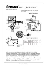
Instructions for changing the coilheater or thermocouple.<br />
Disassembly<br />
Assembly.<br />
1. Take off the reflector (aluminium tube)<br />
2. Unscrew the screws at the rear end.<br />
3. Take off the flange.<br />
4. Take of the lock ring at the front end.<br />
5. Take off the spring that keeps thermocouple in place.<br />
6. Take off the tape that keeps heater and thermocouple extensions<br />
together.<br />
7. Depending on how hard spiral heater fits the pipe it can either be pulled<br />
of or ”unscrewed”. Unscrewing works easily if you push on the spiral<br />
heater extension which will open the spiral while at the same time opening<br />
the spiral at the other end with a suitable tool. The thermocouple must not<br />
follow if the spiral element is rotated or pulled off, since it may break.Treat<br />
thermocouple with great care. The<br />
tube is only 1 mm diameter.<br />
To be done in opposite order to disassembly.<br />
If a new thermocouple is to be fitted it must be<br />
bent to fit the bushing. The tip of the thermocouple<br />
must be located where the groove ends,<br />
i.e. about half-way along the tube. Min. bending<br />
radius 3 mm.<br />
Tighten the element so that the heating spiral<br />
makes contact with the tube.<br />
If you have any questions about installing the bushing, please get in touch with us.<br />
<strong>ESB2</strong><br />
Box 236 S–532 23 Skara Phone: +46 511-13200<br />
e-mail: hot.runner@heatlock.se Fax: +46 511-17285<br />
Homepage: http://www.heatlock.se<br />
<strong>Heatlock</strong> AB 97.06 / <strong>ESB2</strong>.mont<br />
Appendix – 10<br />
Date: 050326, © <strong>Heatlock</strong> AB<br />
© LKM <strong>Heatlock</strong> Co Ltd