You also want an ePaper? Increase the reach of your titles
YUMPU automatically turns print PDFs into web optimized ePapers that Google loves.
A MEGA<br />
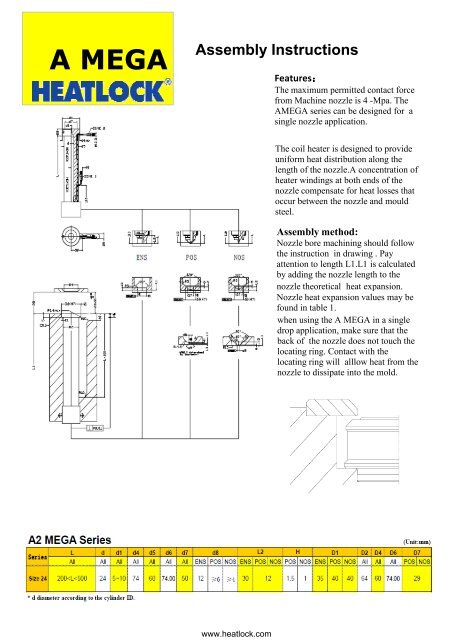
<strong>Assembly</strong> Instructions<br />
Features:<br />
The maximum permitted contact force<br />
from Machine nozzle is 4 -Mpa. The<br />
AMEGA series can be designed for a<br />
single nozzle application.<br />
The coil heater is designed to provide<br />
uniform heat distribution along the<br />
length of the nozzle.A concentration of<br />
heater windings at both ends of the<br />
nozzle compensate for heat losses that<br />
occur between the nozzle and mould<br />
steel.<br />
<strong>Assembly</strong> method:<br />
<strong>Nozzle</strong> bore machining should follow<br />
the instruction in drawing . Pay<br />
attention to length L1.L1 is calculated<br />
by adding the nozzle length to the<br />
nozzle theoretical heat expansion.<br />
<strong>Nozzle</strong> heat expansion values may be<br />
found in table 1.<br />
when using the A MEGA in a single<br />
drop application, make sure that the<br />
back of the nozzle does not touch the<br />
locating ring. Contact with the<br />
locating ring will alllow heat from the<br />
nozzle to dissipate into the mold.<br />
www.heatlock.com
Length of nozzle<br />
Heat expansion of the nozzle must be considered in order to ensure minimum vestige on the part.<br />
Expansion values (X.xx)various temperatures and nozzle lengths are illustrated in the table below:<br />
Table 1<br />
shot weight per<br />
1.Low viscosity: PS,PE,PP<br />
2.Medium viscosity:ABS SAN PA POM<br />
Note: for filled materials, gate diameter should increase 20% .<br />
The diagram above is a guideline for gate diameters needed for various plastics and shot weights.<br />
Note: If the gate diameter is too small, an unnecessary high bushing temperature will have to be<br />
set for the gate not to freeze between shots. The suggested figures are approximate .Gate<br />
dimensions may be influenced by the shape of the part and the design of the mould,etc.<br />
The balance between shot weight, injection speed, mould temperature , temperature opposite the<br />
gate, cooling around the gate,and injection pressure are all factors that affect gate size . A small<br />
gate freezes quicker than a large one. When injection moulding with very short cycle times and<br />
short injection times, it may be necessary to design gate cooling so that the gate area does not<br />
overheat.<br />
If the sprue bushing is feeding a runner which has a gate into a cavity , it may be suitable to make<br />
the bushing gate larger than actual necessary in order to reduce pressure drop and shear.<br />
If an electric sprue bushing is used, this will reduce the length of flow in cold steel therefore<br />
allowing the reduction of the cross section of the cold runner. This is important in order to get the<br />
shortest possibility of cycle time. Start with a smaller gate than indicated in the table.<br />
www.heatlock.com
Wiring instruction<br />
Attention: Only connectors designed to match the temperature controller are<br />
to be used. Heater and T/C wiring must not be connected in parallel.<br />
10 pin connector:HEATLOCK connections as right:<br />
1.Zone 1 Connect (1)(2)with heater<br />
2. Connect T/C wire (black/red)with (6)<br />
3. Connect T/C wire (white/blue)with (7)<br />
4. ZONE2 Connect (3)(4)with heater<br />
5.Connect T/C wire (black/red)with (8)<br />
6. Connect T/C wire (black/red)with (9)<br />
7. Connect mould with ground wire&insert<br />
Instructions for replacement of heater or T/C<br />
Attention: For best performance use HEATLOCK original components.<br />
Disassembly:<br />
1. Open lock ring.<br />
2. Remove reflector.<br />
3. Carefully slide heater off of nozzle.<br />
4. Remove T/C.<br />
<strong>Assembly</strong>:opposite processing to disassembly<br />
If necessary , replace T/C by inserting new T/C into small hole at the end of<br />
slot .Ensure that the tip is in full contact with the bottom of the bore before<br />
bending the T/C along the slot.Install heater onto nozzle ensuring that the<br />
T/C is not displaced.Bundle the heater and T/C together using high<br />
temperature adhesive tape.<br />
<strong>Nozzle</strong> assembly torque<br />
Size No. Torque(N)<br />
size 24 80<br />
(Table 二 )<br />
*If there are any problems encountered during assembly, please call (86)757- 2639 1992.<br />
www.heatlock.com


