PIANC E-Magazine - PIANC AIPCN welcome
PIANC E-Magazine - PIANC AIPCN welcome
PIANC E-Magazine - PIANC AIPCN welcome

Create successful ePaper yourself
Turn your PDF publications into a flip-book with our unique Google optimized e-Paper software.
144<br />
NOVEMBER<br />
2011<br />
NOVEMBRE<br />
ON COURSE<br />
<strong>PIANC</strong> E-<strong>Magazine</strong><br />
Failure of Gansbaai Leeward<br />
Breakwater: Fines Washout from<br />
Breakwater Core<br />
Some Thoughts on the Economics<br />
of Dry Docks<br />
Stability of Crown Walls of<br />
Cube and Cubipod Armoured Mound<br />
Breakwaters<br />
News from the Navigation Community<br />
The World Association for Waterborne Transport Infrastructure<br />
Association Mondiale pour les infrastructures de Transport Maritimes et Fluviales<br />
<strong>PIANC</strong> E-<strong>Magazine</strong> n° 144, November/novembre 2011
<strong>PIANC</strong>’S PLATINUM PARTNERS<br />
<strong>PIANC</strong> E-<strong>Magazine</strong> n° 144, November/novembre 2011
<strong>PIANC</strong><br />
‘ Setting the Course’<br />
‘ Garder le cap’<br />
ON COURSE<br />
<strong>PIANC</strong> E-<strong>Magazine</strong><br />
144<br />
NOVEMBER<br />
2011<br />
NOVEMBRE<br />
Responsible Editor / Editeur responsable :<br />
Mr Louis VAN SCHEL<br />
Boulevard du Roi Albert II 20, B 3<br />
B-1000 Bruxelles<br />
ISBN: 978-2-87223-170-6 EAN: 9782872231706<br />
All copyrights reserved © Tous droits de reproduction réservés<br />
<strong>PIANC</strong> E-<strong>Magazine</strong> n° 144, November/novembre 2011
<strong>PIANC</strong> E-<strong>Magazine</strong> n° 144, November/novembre 2011
E-MAGAZINE N° 144 - 2011<br />
TABLE OF CONTENTS<br />
TABLE DES MATIERES<br />
Message of the President<br />
Mike Chemaly, Failure of Gansbaai Leeward Breakwater:<br />
Fines Washout from Breakwater Core<br />
6<br />
11<br />
Message du Président<br />
Mike Chemaly, Rupture de la digue de Gansbaai:<br />
entraînement des fines du noyau de la digue<br />
Keith Mackie, Some Thoughts on the Economics of<br />
Dry Docks<br />
23<br />
Keith Mackie, Considérations sur l’économie<br />
des installations de radoub<br />
Jorge Molines, Stability of Crown Walls of Cube and<br />
Cubipod Armoured Mound Breakwaters<br />
News from the navigation community<br />
29<br />
45<br />
Jorge Molines, Stabilité des murs de<br />
couronnement sur des digues à talus<br />
en Cubipod et blocs cubiques<br />
Des nouvelles du monde de la navigation<br />
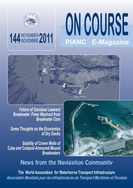
Cover picture:<br />
Gansbaai: New Harbour and location of damage<br />
Photo de couverture:<br />
Gansbaai: nouveau port et localisation des dommages<br />
5<br />
<strong>PIANC</strong> E-<strong>Magazine</strong> n° 144, November/novembre 2011
Message of the President<br />
Nord<strong>PIANC</strong><br />
Thanks to our Estonian section, for the first time the NordPianc Conference was held in Tallinn on September<br />
1-3, 2011. The event took place in the buildings of the Estonian Maritime Administration, where a dedicated<br />
room allows for VTS services along the coast surrounding Tallinn. Together with Louis, we enjoyed a<br />
very nice set of presentations mainly about port layout or buildings and navigation safety issues in the Baltic<br />
Sea. Our colleagues also presented the ice-breaking issues and the fast melting of the Arctic Sea which occurs<br />
twice quicker than expected (both in ice sheet thickness and ice surface). We discovered that the first<br />
Arctic designed container carrier had been ordered so that Arctic navigation issues will become a matter for<br />
<strong>PIANC</strong> soon. The next Nord<strong>PIANC</strong> Conference will take place in Norway. Such local issues are very important<br />
for our members and should be extended to other places in order to strengthen the sense of community<br />
within our Association.<br />
SmartRivers under the <strong>PIANC</strong> umbrella after the New Orleans Conference<br />
Two weeks after the Nord<strong>PIANC</strong> meeting, the US Section of <strong>PIANC</strong> held the 5th SmartRivers Conference<br />
in New Orleans, Louisiana on September 13-16, 2011, which was a special occasion to thank very warmly<br />
both ‘fathers’ of this type of event, Jim McCarville from the US section of <strong>PIANC</strong> and Reinhard Pfliegl from<br />
the Austrian Section. This event was attended by more than 300 participants due to the very active involvement<br />
of the strong organising team, composed by Anne Cann and Kelly Barnes, who deserve our strong<br />
gratitude.<br />
Due to the special location in New Orleans, the US Section was able to invite keynote speakers from both<br />
the US Army Corps of Engineers and the US Coast Guards, which respectively taught us about the major<br />
Greater New Orleans Hurricane and Storm Damage Risk Reduction System (GNOHSDRRS), built after the<br />
terrible Katrina disaster which devastated the city in 2005, as well as about the daily rescue Coast Guards<br />
action during the same disaster but also during the recent major oil spill from the DeepWater Horizon petroleum<br />
Platform.<br />
The so-called GNOHSDRRS project costs more than $ 14.6 billion and is by far the largest project launched<br />
by the US Army Corps of Engineers since the Hoover Dam, with levees, floodwalls and barriers which can<br />
avoid the Gulf surge through navigation channels. It deserves a full publication or at least a full <strong>PIANC</strong> ‘On<br />
Course’, since there is always much to learn from such huge works, even for smaller works!<br />
<strong>PIANC</strong> E-<strong>Magazine</strong> n° 144, November/novembre 2011 6
In my opinion, three major hazard events question the scope which <strong>PIANC</strong> considers to deal either with<br />
natural of with technology-related hazards: Katrina of course and for such large hurricanes, which can affect<br />
many ports, coasts and waterways, tsunami issues with the recent Fukushima disaster in Japan and to<br />
a lesser extent in terms of consequences with the Eyjafjallajoküll volcano eruption which disturbed not only<br />
the whole air traffic on a world scale but also port works, as our Icelandic colleague Sigurdur Gretarsson described<br />
in Tallinn. How can we progress in the way we consider the safety design issues from such events?<br />
Some of our publications dealt with these issues in the past, but we need to undertake a more horizontal<br />
approach on this topic.<br />
At the end of this very fruitful Conference, we were able to sign an agreement between <strong>PIANC</strong> Headquarters<br />
and the organising leaders, Otto Schwetz and Reinhard Pfiegl, which brings a full integration of SmartRivers<br />
within <strong>PIANC</strong>. Like COPEDEC, SmartRivers becomes a full part of <strong>PIANC</strong>. The next SmartRivers Conference<br />
will be hosted both by Belgium (Liège) and The Netherlands (Maastricht) in 2013, which is a very nice<br />
combination.<br />
Future Events<br />
Among our upcoming events there will be our next ExCom, Council and Secretaries meetings in February<br />
2012, as well as the <strong>PIANC</strong>-COPEDEC Conference in Chennai, India. With the World Water Forum in Marseille<br />
in March we expect dedicated presentations about sustainable inland navigation issues.<br />
I wish all of you a pleasant reading and I am eagerly looking forward to receiving more technical articles in<br />
the next E-<strong>Magazine</strong> ‘On Course’!<br />
Geoffroy Caude<br />
President of <strong>PIANC</strong><br />
7<br />
<strong>PIANC</strong> E-<strong>Magazine</strong> n° 144, November/novembre 2011
Message DU Président<br />
Nord<strong>PIANC</strong><br />
Grâce à notre section estonienne, la conférence Nord<strong>PIANC</strong> s’est tenue pour la première fois à Tallinn<br />
du 1 au 3 septembre 2011. L’événement était organisé dans les bâtiments de l’Administration Maritime<br />
estonienne, où une salle particulière était équipée de services VTS surveillant la navigation côtière<br />
autour de Tallinn. Avec Louis, nous avons pu profiter d’une belle série de présentations, qui traitaient<br />
avant tout de la conception ou de la réalisation portuaires, ainsi que de thèmes liés à la sécurité de<br />
la navigation dans la mer Baltique. En outre, nos collègues ont présenté des questions relatives aux<br />
brise-glaces, ainsi qu’à la fonte rapide de la mer Arctique, qui se manifeste deux fois plus rapide que<br />
prévu (tant pour l’épaisseur que pour la surface de la banquise). Nous avons découvert que le premier<br />
porte-conteneurs arctique a été commandé, de sorte que les questions relatives à la navigation arctique<br />
deviendront bientôt aussi des thèmes pour <strong>PIANC</strong>. La prochaine conférence Nord<strong>PIANC</strong> aura<br />
lieu en Norvège. De tels thèmes locaux sont très importants pour nos membres et ils devraient être<br />
étendus à d’autres lieux afin de renforcer le sens de la communauté au sein de notre Association.<br />
SmartRivers sous l’égide de <strong>PIANC</strong> après la Conférence à la Nouvelle<br />
Orléans<br />
Deux semaines après la conférence Nord<strong>PIANC</strong>, la section américaine de <strong>PIANC</strong> tint la 5ème Conférence<br />
SmartRivers à la Nouvelle Orléans, en Louisiane du 13 au 16 septembre 2011, ce qui représentait une<br />
occasion spéciale pour remercier de tout cœur les deux ‘pères fondateurs’ de ce type d’événement, Jim<br />
McCarville de la section américaine de <strong>PIANC</strong> et Reinhard Pfliegl de la section autrichienne. Plus de<br />
300 participants assistaient à cet événement, grâce à l’engagement très actif de la forte équipe organisatrice<br />
composée d’Anne Cann et de Kelly Barnes, qui méritent notre grande reconnaissance.<br />
Comme la conférence se déroulait à la Nouvelle Orléans, la section américaine eut l’occasion d’inviter<br />
des conférenciers principaux tant de l’US Army Corps of Engineers que de l’US Coast Guards, qui nous<br />
ont respectivement mis au courant du système majeur de réduction des risques sur le plan de dégâts<br />
des tempêtes et des ouragans à la Nouvelle Orléans (SRRDTONO), conçu après le désastre terrible<br />
Katrina, qui détruisit la ville en 2005, ainsi que de l’action de sauvetage quotidienne des gardes-côtes<br />
pendant le même désastre, mais aussi pendant le déversement majeur de pétrole récent venant de la<br />
plateforme de pétrole DeepWater Horizon.<br />
<strong>PIANC</strong> E-<strong>Magazine</strong> n° 144, November/novembre 2011<br />
8
Le projet SRRDTONO coûte plus de $ 14,6 milliards et il s’agit de loin du projet le plus large lancé par<br />
l’US Army Corps of Engineers depuis la construction du Barrage Hoover, avec des digues, des murs de<br />
protection et des barrages capables de faire face à la remontée des surcotes de tempêtes par le biais<br />
de chenaux de navigation. Le projet mérite une publication complète ou au moins une édition spéciale<br />
d’‘On Course’ de <strong>PIANC</strong>, comme il reste toujours beaucoup de leçons à tirer de tels ouvrages énormes,<br />
et ce même pour des ouvrages moins considérables!<br />
A mon avis, trois événements majeurs déterminent si <strong>PIANC</strong> traite soit des risques naturels, soit des<br />
risques technologiques: bien sûr Katrina et les tempêtes et les ouragans, qui peuvent affecter nombre<br />
de ports, de côtes et de voies navigables, les tsunamis, en pensant au désastre récent à Fukushima au<br />
Japon, et à un degré moindre en termes des conséquences à l’éruption du volcan Eyjafjallajoküll, qui<br />
a non seulement perturbé le transport aérien à l’échelle mondiale, mais aussi des travaux portuaires,<br />
comme notre collègue islandais Sigurdur Gretarsson nous l’a expliqué à Tallinn. Comment pouvonsnous<br />
progresser de manière à indiquer ces risques de la sécurité de nos infrastructures? Dans le<br />
passé, certaines de nos publications traitaient de ces questions, mais il faut que nous adoptions une<br />
approche plus horizontale vis-à-vis de cette thématique.<br />
A la fin de cette conférence particulièrement réussie nous avons pu signer un accord entre le secrétariat<br />
général de <strong>PIANC</strong> et les organisateurs principaux, Otto Schwetz et Reinhard Pfliegl, qui intègre complètement<br />
SmartRivers au sein de <strong>PIANC</strong>. Par analogie avec COPEDEC, SmartRivers devient donc<br />
une conférence régulière de <strong>PIANC</strong>. La prochaine conférence SmartRivers aura lieu tant en Belgique<br />
(à Liège) qu’aux Pays-Bas (à Maastricht) en 2013, ce qui représente une excellente combinaison.<br />
Evénements futurs<br />
Parmi nos événements à venir, il y aura les réunions de l’ExCom, du Conseil et des Secrétaires au mois<br />
de février 2012, ainsi que la Conférence <strong>PIANC</strong>-COPEDEC à Chennai, en Inde. Lors du Forum Mondial<br />
de l’Eau à Marseille au mois de mars nous attendons aussi des présentations consacrées à des questions<br />
de la navigation intérieure durable.<br />
Je vous souhaite une agréable lecture et j’espère beaucoup recevoir davantage d’articles techniques<br />
dans les prochaines éditions du magazine électronique ‘On Course’!<br />
Geoffroy Caude<br />
Président de <strong>PIANC</strong><br />
9<br />
<strong>PIANC</strong> E-<strong>Magazine</strong> n° 144, November/novembre 2011
<strong>PIANC</strong> E-<strong>Magazine</strong> n° 144, November/novembre 2011 10
Failure of Gansbaai Leeward Breakwater:<br />
Fines Washout from Breakwater Core<br />
by<br />
MIKE CHEMALY<br />
Pr. Eng, B. Eng, M. Eng<br />
WSP Africa Coastal Engineers<br />
PO Box 413<br />
Stellenbosch<br />
South Africa<br />
Tel.: +27 21 883 9260<br />
E-mail: mike.chemaly@wspgroup.co.za<br />
KEY WORDS<br />
Wash out, fines, breakwater core, failure mechanism,<br />
single layer rock<br />
MOTS-CLEFS<br />
m and Ch 126 m armour rock from the crest, slope<br />
and toe had been removed by wave action.<br />
Breakwater failure is attributed to two separate<br />
failure mechanisms, as described further on in this<br />
paper.<br />
Erosion massive, fines, noyau, mécanisme de<br />
rupture, simple couche d’enrochements<br />
1. INTRODUCTION<br />
Gansbaai is situated along the South African<br />
coastline approximately 65 km northwest from the<br />
southernmost tip of Africa. Gansbaai’s New Fishing<br />
Harbour was constructed in two phases over<br />
a period of almost 20 years. Phase I was between<br />
1965 and 1969. Phase II commenced in 1979.<br />
The wave height regime in this part of the world is<br />
severe. Wave heights in the order of 8 m to 9 m<br />
within a few hundred metres just offshore of Gansbaai’s<br />
New Fishing Harbour are not uncommon<br />
during an average winter season.<br />
The Leeward Breakwater to Gansbaai’s New Harbour<br />
is 200 m long. Structural failure over 60 m of<br />
breakwater length initiated emergency repairs to<br />
this section of the breakwater. Complete breakwater<br />
failure between Ch 66 m and Ch 96 m (30 m<br />
length) and rock armour structural failure between<br />
Ch 96 m and Ch 126 m (30 m length) took place.<br />
Between Ch 66 m and Ch 96 m all armour rock<br />
and core material was washed out. In the process<br />
the concrete roadway collapsed. Between Ch 96<br />
11<br />
Gansbaai – South Africa<br />
Gansbaai – New Harbour and location<br />
of damage<br />
<strong>PIANC</strong> E-<strong>Magazine</strong> n° 144, November/novembre 2011
Ch 66 m – Ch 96 m Failure mechanism 1 Failure of armour rock to shoulder, slope and toe.<br />
Ch 66 m – Ch 96 m Failure mechanism 2 Loss of fines in core and collapse of concrete roadway.<br />
Ch 96 m – Ch 126 m Failure mechanism 1 Failure of armour rock to shoulder, slope and toe.<br />
2. EXISTING CROSS-SECTION<br />
In the 60 m of damaged area (Ch 66 m and Ch<br />
126 m) the existing breakwater cross-section was<br />
made up as follows. The core consisted of 0-500<br />
kg material. The grading distribution of the core<br />
was unknown at the time of tender. The core was<br />
overlain by a 500 mm thick x 7 m wide concrete<br />
roadway. The sea facing roadway edge had a<br />
900 mm high parapet wall. The core slopes were<br />
shaped to 2V:3H and overlain by a double layer<br />
1-3 t armour rock.<br />
The entire breakwater cross-section is underlain<br />
by a near horizontal plane of bedrock. This bedrock<br />
profile has a final ground level on roughly<br />
+0.3mCD. This level coincides with the Mean Low<br />
Water Spring level of +0.27mCD. This horizontal<br />
plane of bedrock extends roughly 2 m past the armour<br />
rock toe, after which it dips steeply to form a<br />
vertical reef like edge.<br />
The harbour master indicated that wave related<br />
damage took place during a single storm event<br />
in May 2010. Wave Watch III data indicate wave<br />
heights in excess of 10 m originating from a westerly<br />
direction during this time. The lee breakwater<br />
is facing the open ocean in a NNE direction.<br />
Damage was severe as wave action caused 1-3<br />
t armour rock and 0-500 kg core rock to be displaced<br />
by almost 30 m onto the adjacent Ch 54<br />
m to Ch 66 m portion of the breakwater. This failure<br />
mechanism (referred to as Failure Mechanism<br />
1) resulted in a 30 m section of rock of the Lee<br />
Breakwater of the Gansbaai New Harbour to have<br />
failed completely (Ch 66 m to Ch 96 m). Another<br />
30 m section of breakwater (Ch 96 m to Ch 126 m)<br />
had partially failed due to Failure Mechanism 1.<br />
Core material between Ch 66 m to Ch 96 m (30 m<br />
length) under the concrete roadway was removed<br />
to such an extent that one could easily crawl in underneath<br />
the concrete roadway. The cavity formed<br />
varied between 1,000 mm deep at the entrance<br />
tapering down to 500 mm deep under the roadway.<br />
This loss of material from under the roadway<br />
caused the 500 mm thick concrete roadway to<br />
3. DAMAGE SUSTAINED TO<br />
EXISTING BREAKWATER<br />
settle causing a massive concrete shear crack<br />
running along the length of the roadway. The<br />
crack extended for 30 m from top to bottom of the<br />
concrete structure. It was thought during design<br />
phase that the loss of material under the concrete<br />
roadway was due to excessive wave action only.<br />
<strong>PIANC</strong> E-<strong>Magazine</strong> n° 144, November/novembre 2011<br />
12
1,000 mm deep by 30m long<br />
entrance under structure<br />
Shear crack running for 30 m<br />
along structure length<br />
Rock armour defence collapsed<br />
Breakwater founded on rock reef<br />
4. FAILURE MECHANISM 1<br />
The breakwater is 200 m in length. A plunging<br />
breaker forms during stormy conditions between<br />
Ch 66 m to Ch 96 m. This coincides with where<br />
complete breakwater failure took place. In addition,<br />
in this section superposition of waves takes<br />
place due to a combination of the wave reflecting<br />
off the reef face and the incoming wave. Wave<br />
breakage along other areas along the lee breakwater<br />
are either surging breakers or spilling breakers.<br />
The combination of (a) a wave plunging on a<br />
breakwater toe that is (b) underlain by a hard rock<br />
surface under (c) shallow water conditions is a<br />
classical setup to induce failure if the mass of the<br />
breakwater’s toe is not properly designed. In this<br />
instance the hard rock surfaces cause wave energy<br />
to bounce upwards and in the process displacing<br />
the toe and subsequently leading to failure<br />
of the breakwater toe and causing the rest of<br />
the rubble structure to collapse. This is illustrated<br />
clearly in Figure VI-2-39 in the Coastal Engineering<br />
Manual.<br />
13<br />
<strong>PIANC</strong> E-<strong>Magazine</strong> n° 144, November/novembre 2011
5. DESIGN BASED ON FAILURE<br />
MECHANISM 1<br />
As mentioned above, at this point in time it was<br />
believed the only failure mechanism was Failure<br />
Mechanism 1. Design of the breakwater repairs<br />
by WSP Africa Coastal Engineers based in South<br />
Africa, combined with budgeting constraints imposed<br />
by the client led to the following:<br />
Ch 66 m to Ch 96 m (30 m length)<br />
• Demolish the affected 30 m section of concrete<br />
roadway.<br />
• Replace lost core with 10-500 kg core material.<br />
(The original 0-10 kg fragment of the 0-500 kg<br />
size range was omitted in the tender design to<br />
comply to filter rules).<br />
• Rebuild concrete roadway to 800 mm thick.<br />
(The original structure was 500 mm thick).<br />
• Rebuild 1-3 t double layer rock profile to original<br />
2V:3H lines and levels by using existing rock<br />
and importing the shortfall (if any).<br />
• Overlay the 1-3 t double layer rock armour with<br />
a single layer 4-6 t rock armour to 2V:3H slope.<br />
Ch 96 m and Ch 126 m (30 m length)<br />
• Rebuild 1-3 t double layer rock profile to original<br />
2V:3H lines and levels by using existing rock<br />
and importing the shortfall (if any).<br />
<strong>PIANC</strong> E-<strong>Magazine</strong> n° 144, November/novembre 2011 14
6. COMMENCEMENT OF<br />
CONSTRUCTION<br />
Construction commenced on March 4, 2011. The<br />
contract period was six months. The first step of<br />
the works was to demolish the 30 m portion of<br />
concrete roadway (Ch 66 m to Ch 96 m). However,<br />
upon demolition of the concrete roadway it<br />
was discovered that although the remainder of<br />
the existing core under the demolished concrete<br />
roadway consisted of 0-500 kg material, this material<br />
had an incorrect grading. The grading was<br />
skewered to the left to such an extent that the material<br />
can basically be classified as consisting of<br />
fine quarry run with some isolated larger rock in<br />
between ranging up to 500 kg in size. The grading<br />
did not comply to filter rules. As to be expected<br />
over time all these fines washed out resulting in<br />
the massive cavity under the concrete roadway.<br />
This in turn caused the deck to collapse. This<br />
wash out of core material is referred to as Failure<br />
Mechanism 2. This is illustrated clearly Figure VI-<br />
2-40 in the Coastal Engineering Manual.<br />
Designing and/or constructing breakwaters with<br />
sand cores only and no geomembrane or filter<br />
layers is risky. Breakwaters with a sand core are<br />
classified as having either geometrically open filter<br />
systems or geometrically closed filter systems.<br />
With geometrically open systems the core is only<br />
considered sand tight if the rock layer overlaying<br />
the sand core is of ample thickness to prevent the<br />
mitigation of fines through the material. Currently<br />
limited research had been conducted on geometrically<br />
open filter systems. In this case, however,<br />
sand washed out over time. This breakwater<br />
therefore consists of a geometrically open filter<br />
system being of the non-sandtight type.<br />
After removal of concrete deck:<br />
Test hole at 1 m deep<br />
After removal of concrete deck:<br />
Test hole at 1.5 m deep<br />
15<br />
<strong>PIANC</strong> E-<strong>Magazine</strong> n° 144, November/novembre 2011
7. REDESIGN OF CORE TO<br />
OVERCOME FAILURE MECHANISM 2<br />
The state of the existing core material was unknown<br />
during the design phase (as part of it was<br />
covered under a 500 mm thick deck). In addition,<br />
crawling in under the concrete deck naturally revealed<br />
no fines (as it was all washed out and protected<br />
by a layer of coarser rock that appeared to<br />
be to specification). Therefore, a design change<br />
became vital after construction commenced and<br />
after removal of the dilapidated concrete roadway.<br />
Owing to budgetary constraints the existing fine<br />
core material had to be incorporated into the new<br />
design. The core design between Ch 66 and Ch<br />
96 subsequently changed from the original tender<br />
design, by means of a Variation Order, to the following:<br />
• Reshape existing sand core and cover face with<br />
geotextile.<br />
• Overlay the geotextile with a 450 mm thick layer<br />
of 10-50 kg rock.<br />
• Overlay the 10-50 kg rock layer by a 1,000<br />
mm thick 10-500 kg rock layer. Thus, its profile<br />
would tie into the adjacent core profiles.<br />
• Overlay the 10-500 kg layer with a double layer<br />
1-3 t rock as per the tender design.<br />
• Overlay the 1-3 t rock layer with a single layer<br />
4-6 t rock as per the tender design.<br />
<strong>PIANC</strong> E-<strong>Magazine</strong> n° 144, November/novembre 2011<br />
16
A potential weak spot in the design would be the<br />
interface point between existing and proposed<br />
structure.<br />
Incorporating the geotextile into the design would<br />
prevent existing fines from washing out. The<br />
thicker rock layer would cause more dissipation<br />
of wave energy prior to it reaching the core. In addition,<br />
the 4-6 t rock would be able to withstand<br />
larger wave heights than the initial design.<br />
8. CONTINUATION OF<br />
CONSTRUCTION<br />
After issue of the Variation Order due to the abovementioned<br />
design change, the contractor continued<br />
his operations until completion of the works.<br />
Construction between Ch 66 m and Ch 96 m took<br />
place in the stages depicted below:<br />
Stage 3:<br />
Placing geotextile with 10-50 kg layer overlay.<br />
Stage 1:<br />
Demolition of existing concrete roadway<br />
Stage 4:<br />
Construct 10-500 kg layer to profile<br />
Stage 2:<br />
Trimming back existing sand core<br />
Stage 5:<br />
Casting 800 mm segmented roaway panels<br />
17<br />
<strong>PIANC</strong> E-<strong>Magazine</strong> n° 144, November/novembre 2011
Stage 6:<br />
Complete double layer 1-3 t rock<br />
Stage 9: Completed 7 m wide 800 mm deep<br />
concrete roadway<br />
Construction between Ch 96 m and Ch 126 m<br />
consisted of Stage 6 and Stage 8 only.<br />
9. QUALITY CONTROL<br />
Strict quality control on all concrete and rock was<br />
imposed throughout the project. In addition, all existing<br />
1-3 t rock was salvaged and reused. Quality<br />
control on rock was performed:<br />
• At the quarry<br />
• On site<br />
Stage 7:<br />
Stitchcast parapet walls to concrete roadway<br />
The quarry was located approximately 120 km<br />
from the site of works. This was the closest quarry<br />
to produce 4-6 t rock of this quantity, strength and<br />
size.<br />
The table below indicates indices tested for, specification<br />
requirements of the indices, as well as actual<br />
test results averages obtained.<br />
Stage 8:<br />
Complete single layer 4-6 t rock<br />
1.5 m high drop test. Steel plate on crushed rock.<br />
<strong>PIANC</strong> E-<strong>Magazine</strong> n° 144, November/novembre 2011<br />
18
Solid line – received from quarry<br />
Dots – as per specification<br />
19<br />
<strong>PIANC</strong> E-<strong>Magazine</strong> n° 144, November/novembre 2011
10. PROGRAMME<br />
The Contractor, Guerrini Marine Construction,<br />
based in South Africa, performed good work and<br />
completed the project on time. The contract commenced<br />
on March 4, 2011 and was completed on<br />
September 5, 2011. The actual contract period<br />
was therefore six months which matched the tender<br />
construction period. The only variation order<br />
on the project was the design change due to unforeseen<br />
core material sizes.<br />
11. REFERENCES<br />
CIRIA (2006): “C683, The Rock Manual. The Use<br />
of Rock in Hydraulic Engineering”, 2nd Edition,<br />
(2007), Chapter 3. Engineer Manual (EM) 1110<br />
– 2 – 1100, Coastal Engineering Manual (CEM),<br />
Part VI.<br />
Gansbaai’s New Fishing Harbour is located in an<br />
area along the South African coastline subject<br />
to severe wave conditions. It is located approximately<br />
65 km from the southernmost tip of Africa.<br />
Emergency repairs became vital when sections of<br />
the leeward breakwater failed. A total of 60 m (Ch<br />
66 to Ch 126) of breakwater had failed by March<br />
2011 when the contractor, Guerrini Marine Construction,<br />
based in South Africa, arrived on site.<br />
Along the first 30 m (Ch 66 to Ch 96) of this 60<br />
m section of failed breakwater rock armour was<br />
displaced over a distance of 30 m from the breakwater<br />
due to severe wave action in May 2010.<br />
Wave breaking along this section is in the form<br />
of plunging breakers on a hard rock bed (Failure<br />
Mechanism 1). In addition, the original core that<br />
predominantly consisted of fine material unprotected<br />
by a geomembrane had washed out from<br />
the breakwater core (Failure Mechanism 2). This<br />
resulted in a massive cavity 30 m long by 0.5 m<br />
to 1 m deep forming under the concrete roadway.<br />
Subsequently, the concrete roadway started to<br />
collapse into this cavity.<br />
Along the second 30 m (Ch 96 to Ch 126) of this<br />
60 m section of failed breakwater armour rock was<br />
displaced downwards from the toe, slope and crest<br />
areas of the breakwater. This in turn exposed the<br />
underlying core. In addition, the parapet wall was<br />
exposed and had to absorb direct wave impact.<br />
SUMMARY<br />
The client, the Department of Public Works, acted<br />
swiftly and blocked off access to the breakwater<br />
and fast tracked the design, tender and procurement<br />
phase in order to get the contractor on site<br />
as soon as possible. Combining budgetary constraints<br />
and innovative design by WSP Africa<br />
Coastal Engineers, based in Stellenbosch, South<br />
Africa, the following solutions were catered for.<br />
In general:<br />
• For sustainability reasons WSP Coastal decided<br />
to salvage and re-use all existing 1-3 t rock.<br />
Along the first 30 m of damage sustained (Ch 66<br />
to Ch 96):<br />
• Demolish existing concrete roadway.<br />
• Trim back existing sandy core and overlay with<br />
geomembrane, 10-50 kg rock and 10-500 kg<br />
rock.<br />
• Rebuild concrete roadway to 800 mm thickness<br />
and stichcast precast parapet walls to roadway.<br />
• Reconstruct original 1-3 t double rock protection.<br />
• Construct new single layer 4-6 t armour rock.<br />
Along the second 30m of damage sustained (Ch<br />
96 to Ch 126):<br />
• Salvage and reconstruct original 1-3 t double<br />
rock protection.<br />
• Construct new single layer 4-6 t armour rock.<br />
The contract commenced on March 4, 2011 and<br />
was completed on September 5, 2011. The tender<br />
contract duration was six months. The contractor<br />
did well to complete the project within this time<br />
frame.<br />
<strong>PIANC</strong> E-<strong>Magazine</strong> n° 144, November/novembre 2011 20
Le nouveau port de pêche de Gansbaai est situé<br />
dans une zone le long du littoral sud-africain<br />
sujette à des conditions de houles sévères. Il est<br />
situé approximativement à 65 km de la pointe la<br />
plus au sud de l’Afrique. Les réparations d’urgence<br />
sont devenues nécessaires quand le talus arrière<br />
de la digue rompit. Un total de 60 m (Ch 66 à Ch<br />
126) de digue avait rompu en Mars 2011 quand<br />
l’entrepreneur, Guerrini Marine Construction est<br />
arrivé sur le site.<br />
Sur les trente premiers mètres (Ch 66 à Ch 96)<br />
des soixante du linéaire endommagé, les enrochements<br />
ont été déplacés sur une distance de<br />
30 mètres depuis la digue en raison des fortes<br />
actions de la houle en Mai 2010. Le déferlement<br />
des vagues le long de ce linéaire est du type<br />
plongeant sur un socle rocheux (mécanisme de<br />
rupture 1). En outre, le noyau initial de la digue,<br />
qui est constitué majoritairement de matériau fin<br />
non protégé par une géomembrane, a été lessivé:<br />
des matériaux ont été extraits du noyau (mécanisme<br />
de rupture 2). Cela a eu pour conséquence<br />
une cavité importante de 30 m de long et profonde<br />
de 50 cm à 1 m, formée sous la route en béton.<br />
Par conséquent, cette dernière a commencé à<br />
s’effondrer dans la cavité.<br />
Sur les 30 m suivants (Ch 96 à Ch 126), les enrochements<br />
provenant du pied, de la pente et de<br />
la crête ont été déplacés vers le bas. Cela exposa<br />
le noyau sous-jacent. De plus, le mur de couronnement<br />
fut exposé et encaissa directement les<br />
impacts des vagues.<br />
Le maître d’ouvrage, le Département des Travaux<br />
Publics, a agi rapidement et a rendu inaccessible<br />
la digue. Il lança rapidement les phases d’études<br />
et d’appels d’offres pour trouver une entreprise de<br />
travaux le plus rapidement possible. En prenant<br />
en compte les contraintes budgétaires et la conception<br />
innovante proposée par WSP Coastal Africa<br />
Engineers, basé à Stellenbosch en Afrique du<br />
Sud, les solutions suivantes furent proposées.<br />
RéSUMé<br />
Sur tout le linéaire:<br />
• Pour des raisons de développement durable,<br />
WSP Coastal a décidé de récupérer et réutiliser<br />
tous les enrochements de 1-3 t.<br />
Sur les 30 premiers mètres de dommages (Ch 66<br />
à Ch 96):<br />
• Démolir la route en béton existante.<br />
• Régaler l’ancien noyau en sable et le couvrir<br />
avec une géomembrane puis d’enrochement<br />
de calibre 10-50 kg et 10-500 kg.<br />
• Reconstruire la route d’une épaisseur de 800<br />
mm et un mur de couronnement en éléments<br />
préfabriqués.<br />
• Reconstruire à l’original la double couche<br />
d’enrochements protection.<br />
• Construire une nouvelle couche simple<br />
d’enrochements de carapace de calibre 4-6 t.<br />
Sur les seconds 30 mètres de dommages (Ch 96<br />
à Ch 126):<br />
• Récupération et reconstruction de la double<br />
couche initiale en enrochements de protection<br />
de calibre 1-3 t.<br />
• Construire une nouvelle couche simple<br />
d’enrochements de carapace de calibre 4-6 t.<br />
Les travaux ont commencé le 4 mars 2011 et ont<br />
été réceptionnés le 5 septembre 2011. L’offre prévoyait<br />
une réalisation en 6 mois. L’entrepreneur a<br />
terminé son projet dans les délais.<br />
21<br />
<strong>PIANC</strong> E-<strong>Magazine</strong> n° 144, November/novembre 2011
Der neue Fischereihafen von Gansbaai befindet<br />
sich ca. 65 km von der Südspitze Afrikas an einer<br />
Küste, die einem rauen Wellenklima ausgesetzt<br />
ist. In März 2011 waren bereits 60 m des Wellenbrechers<br />
zerstört.<br />
Auf den ersten 30 m war die Gesteinsabdeckung<br />
durch den starken Wellengang im Mai 2010 mehr<br />
als 30 m weit vom Wellenbrecherkörper weggespült.<br />
Die Wellen treffen in diesem Abschnitt in<br />
Form von Sturzbrechern auf eine Festgesteinsschicht<br />
auf (Versagens-mechanismus 1). Zusätzlich<br />
wurde der ursprüngliche Dammkern, der vorwiegend<br />
aus Feinmaterial ohne Geomembranschutz<br />
bestand, herausgespült (Versagensmechanismus<br />
2). Dies führte zu einer Aushöhlung um 0,5 bis 1<br />
m Tiefe über eine Länge von 30 m unter der Betonstraße,<br />
die daraufhin einzubrechen begann.<br />
Auf den nächsten 30 m war das gesamte Steindeckwerk<br />
vom Fuß, von der Böschung und von<br />
der Krone des Wellenbrechers weggerutscht, so<br />
dass der Dammkern freilag. Zudem war die Begrenzungsmauer<br />
der Betonstraße freigelegt und<br />
der direkten Welleneinwirkung ausgesetzt.<br />
Allgemeines:<br />
• Aus Gründen der Nachhaltigkeit beschloss WSP<br />
Coastal das gesamte vorhandene Gesteinsmaterial<br />
(1 bis 3 t) zu bergen und wieder zu verwenden.<br />
Sanierung:<br />
Auf den ersten 30 m der beschädigten Strecke<br />
(Ch 66 bis Ch 96):<br />
• Rückbau der Betonstraße.<br />
• Neueinbau des vorhandenen Sandkerns und<br />
Abdeckung mit einer Geomembran/Gesteinschicht<br />
(10-50 kg und 10-500 kg Steine).<br />
• Neubau der Betonstraße mit einer Schichtdicke<br />
von 800 mm und vorgefertigten Brüstungswänden<br />
• Rekonstruktion der ursprünglichen 1-3 t doppelten<br />
Steinschutzschicht.<br />
• Aufbau einer neuen einlagigen Deckschicht mit<br />
4-6 t Steinen.<br />
ZUSAMMENFASSUNG<br />
Auf der weiteren 30-m Schadstrecke (Ch 96 bis<br />
Ch 126):<br />
• Bergung und Rekonstruktion der ursprünglichen<br />
1-3 t doppelten Steinschutzschicht.<br />
• Aufbau einer neuen einlagigen Deckschicht mit<br />
4-6 t Steinen.<br />
Die Bauzeit begann am 4. März 2011 und endete<br />
am 5. September 2011.<br />
<strong>PIANC</strong> E-<strong>Magazine</strong> n° 144, November/novembre 2011 22
Some Thoughts on the Economics of Dry Docks<br />
by<br />
KEITH MACKIE<br />
Consulting Coastal & Harbour Engineer<br />
36 Fishermans Bend<br />
Llandudno 7806<br />
Cape Town<br />
South Africa<br />
Tel.: +27 21 790 2263<br />
E-mail: keith@mackie.co.za<br />
Dry Docks, Ship Repair, Economics<br />
KEY WORDS<br />
MOTS-CLEFS<br />
Installations de radoub, réparation navale, économie<br />
1. INTRODUCTION<br />
The following comments are a distillation of forty<br />
years of experience with dry docks and the technology<br />
of dry docks. As such they are pragmatic<br />
and much of the basis has been developed as<br />
part of feasibility studies or the development of actual<br />
projects. Some aspects have been included<br />
in refereed papers and are hence persuasive but<br />
a word of caution: these comments have not yet<br />
been formally examined in a scientific way. The<br />
most significant aspect I foresee comes from the<br />
relatively simplistic presentation given here. In<br />
practice there may well be a great deal of variation<br />
from individual case to individual case.<br />
2. ECONOMIC BASIS OF<br />
DRY DOCKING<br />
The economics of dry docks are somewhat peculiar.<br />
As a rule of thumb, ship owners will accept<br />
a docking fee that does not exceed 10 % of the<br />
overall cost of the work done during the docking<br />
without complaining. Generally, ships are mobile<br />
and they will begin to think of going to other<br />
ports if the charges rise too high. Where the site<br />
is relatively isolated, the dock can get away with<br />
somewhat higher charges before resistance sets<br />
in. Docking charges at this 10 % level are generally<br />
sufficient to cover operating costs and running<br />
maintenance. But it is completely inadequate to<br />
cover the amortisation of the capital cost. Again,<br />
as a rule, dock costs are scale dependent, i.e.<br />
both the capital cost and the operating and maintenance<br />
costs, expressed as cost per tonne of capacity,<br />
are least for large docks and greatest for<br />
small docks.<br />
Ship repairers can afford to acquire their own<br />
docks. If they own the dock, they not only control<br />
their business, they control the whole of the monies<br />
spent on ship repair during docking and the<br />
profit on these monies. They can afford to plough<br />
back a significant portion of their profit in amortising<br />
the dock. Not only does the money stay in<br />
the business as capital asset, the tax benefits of<br />
the write-off of this investment create a gearing effect<br />
that increases the apparent amount of money<br />
invested. This does mean that the valuation of a<br />
ship repair company, owning its own dry dock, is<br />
characterised by a very large single asset.<br />
Alternatively, a dry dock facility can be a ‘common<br />
user facility’ by which is meant a facility where<br />
anyone, boat owner, ship repairer or agent etc.<br />
can bring a ship to dock; where anyone, the owner<br />
himself or any ship repairer or contractor duly appointed<br />
can work on the vessel.<br />
23<br />
<strong>PIANC</strong> E-<strong>Magazine</strong> n° 144, November/novembre 2011
If a dry dock is unencumbered by any capital cost<br />
and is endowed to some extent to assist with occasional<br />
major maintenance costs, then it can operate<br />
as a viable but not very profitable common<br />
user facility. This unlikely scenario could perhaps<br />
occur where a military dock, no longer needed,<br />
is donated to a community or to a training facility<br />
teaching ship repair and dry dock operation.<br />
To any fleet whether it be shipping, fishing, undersea<br />
mining, oil exploration or any other function<br />
and the community it supports, a dry dock, however<br />
it is owned, is a major communal asset. Not<br />
only does it make possible the economic activity<br />
of the fleet that sustains the community – ships<br />
cannot continue to operate without the back up of<br />
dry docks and ship repair – it also provides ship<br />
repair as an added source of employment for the<br />
community.<br />
Ship repairer ingenuity: semi-sub<br />
on a heavy lift vessel.<br />
Even if there is only one dry dock in a port and it<br />
is owned by the local ship repairer, unless the port<br />
is remote from any other ports with docking facilities,<br />
it will not constitute a monopoly with respect<br />
to shipping. However, with respect to employment<br />
in the dock and to the local community, it will.<br />
1,200 tonne Henderson Slipway constructed in 1945 to military specifications –<br />
still in use as common user facility. An estimate of the load capacity of the keel ways beam,<br />
assuming 25 MPa concrete, is sufficient for the keel block loading of a Panamax container ship.<br />
<strong>PIANC</strong> E-<strong>Magazine</strong> n° 144, November/novembre 2011 24
The public sector, whether it be local, regional or<br />
national, if it benefits from the tax revenues that<br />
flow from shipping and the associated ship repair,<br />
has a duty to ensure that dry docking facilities are<br />
available as communal assets. In some cases, the<br />
ship repairer industry will be able to provide such<br />
facilities. Where this is possible, the public sector<br />
will be well advised to avoid becoming involved<br />
in the ownership of dry docks. Instead, so far as<br />
possible, they should co-operate with the ship repairers<br />
and assist them in acquiring their facilities.<br />
However, they must also ensure that there are a<br />
number of ship repairers each with their own dry<br />
dock facilities to avoid a monopoly situation. If the<br />
ship repairers do not provide the facilities, then it<br />
is up to the public sector to do so in the interests<br />
of the community.<br />
The total annual tax revenues, both direct and<br />
indirect, generated from shipping and ship repair<br />
activities will far exceed the net annual liabilities of<br />
the dry docking facility – total annual costs, capital<br />
amortisation, major maintenance and capital improvements,<br />
running maintenance and operating<br />
costs less income from docking charges.<br />
A warning, however: the provision of a publicly<br />
owned common user dry dock leads to ‘riding a<br />
tiger’. Once a dock becomes a common user facility,<br />
it is difficult to revert to ship repairer ownership.<br />
The business models of the community, the fleet<br />
and particularly the ship repairers become completely<br />
oriented to this common user access to the<br />
facility of the dock. The sale of a public dock to<br />
a single ship repairer will lead to a catastrophic<br />
disruption of the local business environment. The<br />
economics of dry docks mean that the new owner<br />
has no option but to run it for his exclusive use. If<br />
it is the only dock in a port or a region, ship repair<br />
using that dock becomes a monopoly. The community<br />
and the fleet can only do business with the<br />
owner and the other ship repairers can only remain<br />
in business if they can find employment as<br />
sub-contractors to the owner.<br />
The provision of competent management and operating<br />
staff is another problem for public docks.<br />
The shipping industry in general, ship repair in<br />
particular – at an artisan level, shipwrights – are<br />
well able to adapt to this function but it does not<br />
lend itself to general administrative, commercial or<br />
non-maritime industrial capabilities. Hence, one<br />
finds that public docks are commonly operated by<br />
port authorities.<br />
Two interesting case studies are the South African<br />
Commercial Ports and the South African Fishing<br />
Harbours.<br />
South Africa has more dry docking capacity than<br />
any other Southern Hemisphere nation – almost<br />
as much as the rest put together. The large facilities<br />
in the commercial ports were all built between<br />
1880 and 1945 at the behest of the Royal Navy as<br />
military facilities and were joint ventures between<br />
them and the South African government. The assets<br />
and the operation were placed with the port<br />
authorities. At the time, they operated as a service<br />
entity. The economics of dry docks did not enter<br />
the picture. The facilities were well run and maintained<br />
and charges were reasonable. Since then<br />
the port authority has been restructured and run<br />
as a commercial entity. Now the economics of the<br />
dry docks are relevant. Charges have increased,<br />
service and maintenance have decreased, and<br />
the Port Authority has not entertained any expansion<br />
of dry docking facilities. Currently they are<br />
looking for ways to privatise the facilities. Despite<br />
a major feasibility study, they have been unsuccessful<br />
to date.<br />
The South African pelagic fishery came into existence<br />
explosively in the aftermath of WWII. Starting<br />
with relatively small purse-seiners with a relatively<br />
small range, the industry based itself at small<br />
harbours spread along the coast at, what at that<br />
time were remote, undeveloped sites. The capital<br />
requirements meant that the participants were<br />
large companies able to construct fish processing<br />
factories at these sites and, initially, to construct<br />
minimal harbour facilities including slipways<br />
to service the boats. In the mid 1960’s the state<br />
stepped in to build proper small harbours at these<br />
sites including much more sophisticated slipways<br />
– a process that evolved the ‘Cape’ type slipway.<br />
Once these common user facilities became available,<br />
the fishing companies allowed their own facilities<br />
to degenerate and soon abandoned them.<br />
The only private slipway still operating is owned<br />
by a ship repairer.<br />
Given the comments above, there is no easy way<br />
to dispose of a public dock, even if there is a compelling<br />
reason to do so. Where, to avoid this, the<br />
25<br />
<strong>PIANC</strong> E-<strong>Magazine</strong> n° 144, November/novembre 2011
The hazards of towing the vessel to the dockyard.<br />
asset is transferred to the port authority, more<br />
problems arise. The apparent value will inflate<br />
their asset register but, since the object is to provide<br />
a common user facility, there will be no concomitant<br />
return on investment and this in turn will<br />
reflect on the authority’s balance sheet.<br />
The only practical way around this is to keep all<br />
the financials, asset, costs and incomes in the<br />
public domain and acquire the use of the site by<br />
purchase or rent as appropriate. Operation and<br />
management of the docks and provision of technical<br />
guidance on major maintenance or capital<br />
improvements can be provided on a contract basis<br />
with the port authority or any other competent<br />
entity. If, however, the scope and number of dry<br />
docking facilities justifies it, a dedicated, competent<br />
public institution can be established to handle<br />
all these functions and still provide dry docking on<br />
a common user basis.<br />
The hazards of towing the dock to the vessels.<br />
<strong>PIANC</strong> E-<strong>Magazine</strong> n° 144, November/novembre 2011 26
3. REFERENCES<br />
Clark, E.: “Hydraulic Lift Graving Dock”, Min. Proc<br />
ICE Vol 25, 1865-66.<br />
Mackie, K.P. (May 2010): “The 1890 Blackwood<br />
Screw Jack Shiplift, Barbados”, <strong>PIANC</strong> MMX, Liverpool.<br />
Mackie, K.P. (May 2007): “South African Dry Docking<br />
Facilities”, Civil Engineering: SAICE, vol 15,<br />
no 5.<br />
Mackie, K.P. (1999): “Small Mechanical Dry Docking<br />
Systems”, Fifth International Conference<br />
on Coastal and Port Engineering in Developing<br />
Countries, Cape Town.<br />
Mackie, K.P. and Deane, R.F. (2006): “Issues in<br />
Dry Docking – Economics, Shiplifts, Slipways and<br />
Keel Blocks”, 31st <strong>PIANC</strong> Congress, Lisbon.<br />
Although of a crude nature, a number of rules of<br />
thumb characterise the economics of dry docks<br />
quite reliably. These economics are dominated by<br />
the pattern of ownership of the dock. Almost inevitably,<br />
either a dry docking facility is owned by<br />
a ship repairer who will have exclusive use of the<br />
Quelques règles de bases simples caractérisent<br />
bien l’économie des installations de radoub. Cette<br />
économie est dominée par le type de propriété de<br />
l’installation. Dans presque tous les cas les installations<br />
sont soit la propriété d’un réparateur qui<br />
SUMMARY<br />
RéSUMé<br />
dock or it is owned by the public sector and run as<br />
a common user facility. The economics of these<br />
two systems are quite different. The failure to understand<br />
these basics can cripple a proposal for a<br />
dry docking facility.<br />
en a l’usage exclusif, soit gérées comme un bien<br />
public. Les fonctionnements économiques de ces<br />
deux systèmes sont profondément différents. Une<br />
méconnaissance de ces fondamentaux peut faire<br />
perdre son intérêt à une installation de radoub.<br />
ZUSAMMENFASSUNG<br />
Die Wirtschaftlichkeit von Trockendocks läst sich<br />
grob anhand einiger Faustregeln charakterisieren.<br />
Trockendockanlagen befinden sich einerseits entweder<br />
im Besitz von Schiffsreparaturbetrieben,<br />
die dann die alleinigen Nutzer dieser Docks sind<br />
oder die Anlagen gehören zum öffentlichen Sektor<br />
und werden allgemein genutzt. Diese beiden<br />
Systeme unterscheiden sich stark in ihrer Betriebswirtschaft.<br />
Mangelndes Verständnis dieser<br />
Grundlagen kann zum Scheitern eines Vorhabens<br />
zur Schaffung bzw. zum Betrieb einer Trockendockanlage<br />
führen.<br />
27<br />
<strong>PIANC</strong> E-<strong>Magazine</strong> n° 144, November/novembre 2011
<strong>PIANC</strong> E-<strong>Magazine</strong> n° 144, November/novembre 2011 28
Stability of Crown Walls of Cube and Cubipod<br />
Armoured Mound Breakwaters<br />
by<br />
JORGE MOLINES<br />
Laboratory of Ports and Coasts<br />
Universidad Politécnica de Valencia<br />
Isabel la Catolica 33 Alcoy (Alicante)<br />
Spain<br />
Tel.: + 34 620 52 86 81<br />
E-mail: jormollo@hotmail.com<br />
Winner of the Modesto Vigueras Award 2010 (Spain)<br />
KEY WORDS<br />
Crown Wall Forces, Crown Wall Stability, Breakwater,<br />
Crown Wall Sliding, Cubipod<br />
MOTS-CLEFS<br />
Efforts sur les murs de couronnement, stabilité<br />
des murs de couronnement, glissement des murs<br />
de couronnement, Cubipod<br />
1. INTRODUCTION<br />
Breakwaters can generally be divided into two<br />
types: vertical and mound breakwaters. The former<br />
reflect the wave energy, with the associated<br />
problems for navigation, but they are cheaper and<br />
more respectful of the environment than the mound<br />
ones. The latter absorb part of the wave energy,<br />
resisting wave action mainly by wave breaking.<br />
Normally, mound breakwaters are crowned with a<br />
concrete superstructure resting on the mound layer<br />
and are partially protected by the armour layer.<br />
The aim is to reduce the amount of concrete used<br />
in armour layers and increase the crest freeboard<br />
while decreasing cost. Crown walls are attacked<br />
by wave impact and earth armour layer pressure,<br />
the former being the most important one due to<br />
the higher value.<br />
Initially, the main layer of mound breakwaters<br />
consisted of quarrystone. As demand for space<br />
in ports grew, it became necessary to place the<br />
breakwaters deeper. At greater depths, no quarry<br />
could provide heavy enough quarrystone, so<br />
prefabricated elements of concrete such as the<br />
Cube, the Tetrapode (1950) or the Dolo (1963)<br />
appeared.<br />
In a mound breakwater there are different types<br />
of failure modes, as shown in Figure 1 by Bruun<br />
(1985): extraction of armour units, overtopping,<br />
erosion of the toe, etc. There are four common<br />
types of failure affecting the crown wall:<br />
1. Sliding is the most common failure mode. It<br />
happens when the horizontal force is greater<br />
than the friction resistance, which can be altered<br />
by ascending pressures.<br />
2. Overturning happens when the unstabilising<br />
moments are larger than the stabilising ones.<br />
3. Cracking refers to the deterioration of the material<br />
throughout its lifetime.<br />
4. Geotechnical failure is the failure of the foundations.<br />
It is caused when the load transmitted<br />
is higher than the load of collapse of the foundations.<br />
Failures modes 2 (overturning) and 3 (cracking)<br />
are easily solved by the proper design of the crown<br />
wall geometry. Failure mode 4 (geotechnical failure)<br />
is related to the foundation soils rather than<br />
to the crown wall design; therefore, sliding is the<br />
most typical critical failure, since it requires building<br />
the crown wall with sufficient weight.<br />
29<br />
<strong>PIANC</strong> E-<strong>Magazine</strong> n° 144, November/novembre 2011
Figure 1. Failure modes of a mound breakwater [Bruun, 1985]<br />
Two processes help to understand the forces<br />
that act on a crown wall: run up and overtopping.<br />
Both phenomena are affected by the armour unit<br />
placed in the main layer. Therefore, it is necessary<br />
to conduct further studies into the crown wall behaviour<br />
with different armour units: Cubic blocks<br />
and Cubipods.<br />
The Cubipod (figure 2) is a prefabricated concrete<br />
block designed to protect marine structures<br />
[Gómez-Martín and Medina, 2007]. The Cubipod<br />
overcomes the disadvantages of the cube while<br />
keeping its advantages: great structural resistance,<br />
simple manufacture and placement, flexible<br />
response to extreme storms, high hydraulic<br />
stability and avoiding the tendency face to face.<br />
The simple protrusion-faced design eliminates the<br />
problem of heterogeneous packing, increasing<br />
the friction with the secondary layer. In addition,<br />
thanks to these protrusions, Cubipod layers display<br />
a rougher surface than cube layers, offering<br />
greater resistance to water rise, while decreasing<br />
run-up, overtopping and forces on the crown wall.<br />
Furthermore, the shape of the Cubipod allows for<br />
the use of constructive methods like those used<br />
in nowadays in cubes with minor modifications.<br />
Corredor et al. (2008) created a flanhole formwork<br />
allowing Cubipod manufacture with outputs similar<br />
to cubes. The formwork consists of two elements:<br />
a static base and a top formwork with six articulated<br />
elements to fill and vibrate in two phases which<br />
are removed after every six hours.<br />
1.1. Wave Action on Crown Walls<br />
Figure 2. The Cubipod<br />
The action of waves on the crown wall of a mound<br />
breakwater is highly influenced by the process<br />
of transformation and breaking conditions of the<br />
rough slope. As the wave approaches the slope,<br />
the fast reduction of the depth and friction with the<br />
bottom makes waves increase in steepness, until<br />
they finally break.<br />
If the waves break by plunging or collapsing, then<br />
a great amount of energy is dissipated in the<br />
slope, transmitting little energy to the crown wall.<br />
In addition, when a wave breaks over the porous<br />
slope, a certain amount of air becomes trapped in<br />
the wave in the form of bubbles. The irregularity of<br />
real swell and the theoretical complexity of these<br />
processes mean that there is currently no precise<br />
and reliable analytical model to predict forces on<br />
crown walls. Therefore, to estimate the forces on<br />
<strong>PIANC</strong> E-<strong>Magazine</strong> n° 144, November/novembre 2011 30
crown walls, Froude similarity and physical model<br />
tests are used to obtain the empirically-related<br />
factors involved in the process and an empirical<br />
calculation method to estimate the forces.<br />
The prediction models proposed over the years<br />
include:<br />
1) Iribarren (1954) proposed triangular distributions<br />
(see Figure 3a) for the dynamic and hydrostatic<br />
pressures, based on the maximum<br />
horizontal crest speed after the wave breaks<br />
on the slope.<br />
2) Jensen (1984) studied the influence of the<br />
wave height, period and sea level. Jensen<br />
(1984) concluded that the influence of sea level<br />
variations can be expressed as the berm freeboard<br />
and that the horizontal force is directly<br />
proportional to Hs/As. The wave period shows<br />
a clear trend: when the period increases, the<br />
forces increase too.<br />
Jensen‘s formulae should only be used when<br />
the input parameters are very similar to those<br />
reported in Jensen (1984), limiting their application<br />
to situations of moderate overtopping.<br />
Jensen (1984) did not propose a distribution<br />
of pressures, so it is not possible to get the<br />
unstabilising moments, although overturning is<br />
not a critical failure mode.<br />
3) Günback and Göcke (1984) proposed a method<br />
to calculate the pressures based on run-up.<br />
They separated the action of the waves on the<br />
vertical wall into two simultaneous distributions:<br />
a hydrostatic one extended up to the end<br />
of the wedge run-up representing the mass of<br />
water that hits the wall and a rectangular one<br />
associated with the kinetic energy of the wave<br />
(see Figure 3b). They proposed a triangular<br />
distribution for the up-lift forces.<br />
4) Bradbury (1988) investigated the influence of<br />
the slope on the loads over the superstructure,<br />
but did not draw clear conclusions about its<br />
influence. The results support those reported<br />
by Jensen (1984), i.e. proportionality between<br />
force and wave height and an increase in the<br />
forces with the wave period.<br />
5) Hamilton and Hall (1992) conducted a parametric<br />
research through laboratory tests to determine<br />
crown wall stability when subjected to<br />
regular waves. Their main findings are:<br />
• The increase in forces is directly proportional<br />
to wave height at moderate overtopping<br />
rates: from this point, the increase in forces<br />
decreases until approaching an horizontal<br />
asymptote.<br />
• Forces increase with the period, but the authors<br />
do not provide clear conclusions.<br />
• The smoother the slope, the lower the forces.<br />
• Crown wall stability greatly decreases when<br />
placed just on the riprap (provided that the<br />
crown walls used in the tests conducted by<br />
Hamilton and Hall (1992) have a smooth<br />
base).<br />
• The use of heels in the crown walls increases<br />
resistance to sliding compared to crown<br />
walls without heels; length is not relevant.<br />
6) Pedersen and Burchart (1992) studied the influence<br />
of certain parameters on the stability of<br />
the crown wall. Their conclusions are similar to<br />
those of Hamilton and Hall (1992) and Jensen<br />
(1984):<br />
• The higher the wave height, the higher the<br />
load on the crown wall.<br />
• The longer the period, the stronger the actions<br />
on the crown wall.<br />
• The Hs/As parameter displays a clear linear<br />
dependence with the force.<br />
• Non-conclusive results are obtained regarding<br />
the influence of the berm width.<br />
• Forces on crown walls depend on the area<br />
non-protected by the berm. When the height<br />
of the vertical wall is very high, a maximum<br />
value that depends only on the sea conditions<br />
and the sea level is reached.<br />
7) Burchart (1993) presented a formula for force<br />
calculation based on the idea of Günback and<br />
Göcke (1984) extending the wedge run-up until<br />
the imaginary prolongation of the slope is<br />
reached. For simplicity, Burchart (1993) did<br />
not separate the force into an impulsive one<br />
and a hydrostatic one, but considered it as<br />
a fictitious hydrostatic force. Burchart (1993)<br />
31<br />
<strong>PIANC</strong> E-<strong>Magazine</strong> n° 144, November/novembre 2011
Figure 3. Pressure schemes by the different authors<br />
concluded that the proposed distribution does<br />
not correctly simulate pressures in the area<br />
protected by the berm, overestimating the<br />
pressures on the base of the crown wall, so<br />
that the up-lift forces yield a very conservative<br />
value (see Figure 3a).<br />
8) Martín et al. (1995) proposed a formula to calculate<br />
the forces in the case of regular waves.<br />
The method is applicable to those crown walls<br />
of mound breakwaters that are not affected by<br />
impact pressures, i.e. those in which the waves<br />
are broken or running up on the slope.<br />
The proposed model is based on the appearance<br />
in the pressures laws of two out-of-phase<br />
peaks in time. The first peak is attributed to<br />
the horizontal deceleration of the water mass,<br />
while the second one is caused by the vertical<br />
acceleration when the accumulated water<br />
descends against the structure. Authors suggested<br />
two distributions for each pressure<br />
peak: for the first one they proposed an almost<br />
rectangular distribution, whereas for the second<br />
one they presented a nearly hydrostatic<br />
distribution (like those described by Günback<br />
and Göcke (1984), see figure 3b).<br />
For the up-lift pressures they proposed a triangular<br />
distribution according to the continuity<br />
of pressures; thus, the designed crown wall is<br />
on the safety side because it is supposed that<br />
wave impact occurs at the same time both on<br />
the vertical wall and on the crown wall base.<br />
9) Pedersen (1996) reached the following conclusions:<br />
• A linear dependency of the force with wave<br />
height exists if there is no overtopping. When<br />
overtopping begins, the force tends towards<br />
an asymptotic value.<br />
• The force is greater with longer wave periods,<br />
assuming that the force-wavelength relation<br />
is linear.<br />
• There is a clear linear dependency between<br />
the horizontal force and 1/Ac.<br />
• There is a clear linear dependency between<br />
the horizontal force and 1/cot .<br />
• The three types of armour units placed randomly<br />
(cubes, quarystone and Dolos) show<br />
almost identical values for the horizontal<br />
force.<br />
• When there is no overtopping, the crown<br />
wall height has no influence on the force.<br />
However, when overtopping exists, the observed<br />
forces are proportional to the square<br />
of the crown wall height.<br />
• The influence of the berm width is not evident.<br />
Pedersen’s (1996) model of pressures, like<br />
in the dynamic distribution by Günback and<br />
Göcke (1984) and Martín et al. (1995), offered<br />
two rectangular distributions: one for the zone<br />
not protected by the berm and the other for the<br />
protected zone (see figure 3c.). For the up-lift<br />
pressures, Pedersen (1996) proposed a triangular<br />
distribution that satisfies the pressure<br />
continuity.<br />
10) Silva R. et al. (1998) extended the Martín et al.<br />
(1995) method to irregular waves by the statistical<br />
characterisation of the run-up, which<br />
fits very well to the run-up values by Van der<br />
Meer (1988).<br />
11) Martín et al. (1999) introduced minor modifications<br />
to Martín et al. (1995), mainly in the<br />
run-up factor that directly affects the horizontal<br />
pressures and in the consideration of the<br />
up-lift pressures.<br />
For the up-lift pressures, they proposed a trapezial<br />
distribution if the foundations are below<br />
the sea level, including the hydrostatic pressure<br />
corresponding to the foundation level.<br />
<strong>PIANC</strong> E-<strong>Magazine</strong> n° 144, November/novembre 2011<br />
32
12) Camus and Flores (2004) evaluate the formulae<br />
by Günback and Göcke (1984), Jensen-<br />
Bradbury (1984, 1988), Pedersen (1996) and<br />
Martín et al. (1999). They conclude that the<br />
Pedersen (1996) method is the approach that<br />
best represents the maximum horizontal forces,<br />
whereas the methodology of Martín et al.<br />
(1999) best represents the physical phenomenon<br />
of wave impact on the crown wall.<br />
13) Berenguer and Baonza (2006) presented a<br />
formula to calculate forces on the crown wall<br />
based on laboratory tests. This formula considers<br />
the influence of the damage level in the<br />
main layer on the wave impact intensity on the<br />
crown wall. They do not propose any distribution<br />
for the horizontal pressures, only a triangular<br />
distribution for the up-lift pressures.<br />
2. EXPERIMENTAL METHODOLOGY<br />
2D physical model tests at a reference scale of<br />
1:50 were carried out in the wind and wave flume<br />
of the Laboratory of Ports and Coasts at the Universidad<br />
Politécnica de Valencia (30 x 1.22 x 1.2<br />
m), which is equipped with a horizontally-moved<br />
trowel impelled by a servovalve. Water depth varies<br />
according to the test, in this case 50 or 55 cm<br />
in the model zone.<br />
2.1. Characteristics of the Tested Models<br />
The model consists of a mound breakwater under<br />
non-breaking conditions with a crown wall on the<br />
top, a slope 1/1.5 on the face exposed to waves,<br />
whose crest level was designed to avoid overtopping<br />
damaging the main layer. Several models<br />
were constructed with the same nucleus, filter and<br />
crown walls, but different armour units for the main<br />
layer: conventional double-layer cube armour of<br />
Dn = 6 cm, double-layer Cubipod armour of Dn =<br />
3.82 cm and single-layer Cubipod armour of Dn =<br />
3.82 cm.<br />
Initially, 4 cm cubes and 3.82 cm Cubipods were<br />
to be tested, but the 4 cm cubes were too unstable<br />
when the waves produced overtopping.<br />
2.2. Constructive Process<br />
and Data Acquisition<br />
First the channel walls are cleaned and the crosssection<br />
of the model is drawn on both sides of the<br />
channel. Then, the nucleus is placed with the correct<br />
slope and crest level.<br />
Figure 4. Longitudinal section of the wind and wave flume at the UPV. Levels in metres.<br />
Figure 5. Section of the model tested<br />
33<br />
<strong>PIANC</strong> E-<strong>Magazine</strong> n° 144, November/novembre 2011
Next, on the top of the nucleus, the crown wall is<br />
placed and a filter constant thickness (about 6.7<br />
cm) is also installed. In the protected area of the<br />
breakwater, heavy material is placed to avoid the<br />
washing of the filter and nucleus by overtopping.<br />
Finally, the main layer is placed; it may consist of<br />
one or two layers, depending on the armour unit:<br />
Cubipods are placed in single and double layers,<br />
whereas cubes are only placed in double layers.<br />
When the double-layer breakwater is tested, the<br />
lower one is white, whereas the upper one is divided<br />
into bands of colours to easily identify where<br />
a piece has been removed. The elements are<br />
placed randomly, simulating the real crane placement<br />
(not placing them in a certain position). As a<br />
consequence, the double-layers cube and Cubipod<br />
armoured breakwater has a porosity of 37 %<br />
and the single-layer Cubipod armoured breakwater<br />
has a porosity of 39 %.<br />
In order to collect the necessary data for a complete<br />
analysis, 8 level sensors were used (separated<br />
according to Mansard and Funke’s (1980)<br />
arrangement), 2 for run-up, one scale for overtopping<br />
and 7 pressure sensors (3 on the base and 4<br />
on the vertical wall). The sampling of the gauges<br />
is 20 Hz, except for the scale, which is 5 Hz.<br />
Incident and reflected wave separation was calculated<br />
using the LASA-V program [Figueres and<br />
Medina, 2004]. The LASA-V program determines<br />
the incident and reflected wave in the time domain<br />
using an approximated model of nonlinear<br />
Sotkes-V wave through simulated annealing processes.<br />
Ascendent or descendent trends were detected in<br />
the pressure sensors because the gauges were<br />
not able to return immediately to zero deformation<br />
after wave impact. To eliminate these tendencies,<br />
mobile averaging techniques were applied (usually<br />
applied in time series).<br />
The constructed mound breakwater was attacked<br />
with regular and irregular waves of normal incidence<br />
maintaining an approximate Iribarren number<br />
(Ir = 2.0, 2.5, 3.0, 3.5 and 4.0 were tested).<br />
During the tests, run-up, overtopping, crown wall<br />
stability and main layer stability were recorded<br />
and analysed, as the wave action on the crown<br />
wall was the main objective of the present study.<br />
The objective of the regular tests was to understand<br />
the response of the model’s section to incident<br />
waves, using the data obtained to better<br />
fit the wave height of zero damage of the irregular<br />
tests. The irregular tests were generated with<br />
1,000 waves and JONSWAP spectrum with a<br />
peak parameter of 3, simulating the real duration<br />
of extreme wave conditions.<br />
3. DATA ANALYSIS<br />
The different formulae were applied to the collected<br />
data to obtain the maximum amount of information<br />
possible from the tests (in some formulae<br />
not all conditions of application were fulfilled). Figure<br />
12 shows all the relative mean square errors<br />
(RMSE (1)).<br />
RMSE = 1 N<br />
N ⋅ ( o i<br />
− e i )<br />
∑<br />
2<br />
(1)<br />
Var (o i<br />
)<br />
i=1<br />
€<br />
Figure 6. Scheme of the sensor distribution<br />
<strong>PIANC</strong> E-<strong>Magazine</strong> n° 144, November/novembre 2011 34
None of the analysed models satisfactorily represented<br />
both the horizontal and the up-lift forces;<br />
thus, a new methodology is proposed. First, the<br />
most relevant variables of the process are studied<br />
and then the pertinent formulae are given using<br />
statistical studies and pruned neural networks.<br />
These formulae estimate the maximum horizontal<br />
force (Fh) and the up-lift force (Fv(Fh)) associated<br />
with the wave that caused Fh (Figure 7). A statistical<br />
analysis of the sliding failure mode (the most<br />
frequent failure) was conducted, which showed €<br />
that the combination (Fh, Fv(Fh)) is the most unfavourable<br />
situation in more than 70 % of the cases<br />
(Figure 8).<br />
The crown wall was considered to fail when an<br />
event larger than the resistant force occurs, no<br />
matter the duration of the event, being on the<br />
safety side.<br />
3.1. Initial Statistical Analysis<br />
The formulae that were obtained can serve to<br />
estimate the maximum horizontal force (Fh) and<br />
the maximum up-lift force corresponding to the<br />
wave that generated the maximum horizontal<br />
force (Fv(Fh)). These actions, although separated<br />
some tenths of a second, were considered to € occur<br />
at the same time on the safety side.<br />
In order to know if the design using Fh and Fv(Fh)<br />
is correct, the crown wall behaviour against sliding<br />
was studied (the most common failure in crown<br />
walls). This is:<br />
• Force data were recorded every 0.05 seconds.<br />
Hence, the failure function can be calculated for<br />
every moment in time<br />
S(t) = ( W − Fv (t))m − Fh(t)<br />
• For each test, S(t) values were ordered from<br />
greater to lower, thus obtaining the most unfavourable<br />
case of the test: the smallest S(t), from<br />
now on Sd.<br />
• On the other hand, the experimental values of<br />
Fh and Fv(Fh) were obtained for each test, and<br />
the failure function<br />
S 1<br />
= ( W − Fv (Fh))m − Fh<br />
could be calculated.<br />
Sd − S 1<br />
• Therefore, € the parameter Fh can be obtained.<br />
If Fh , then the (Fh, Fv(Fh)) es-<br />
Sd − S 1<br />
> 0<br />
timator pair is on € the security side, since<br />
S 1<br />
< Sd .<br />
€<br />
The formulation of sliding failure mode is very sensitive<br />
to the m value, a parameter that presents a<br />
great variability: Goda (1985) and the Japanese<br />
standards [BSI, 1986] suggest 0.6; ROM 0.5-2005<br />
recommends a value of 0.7, etc. For this reason,<br />
Figure 7. F h and Fv (Fh) values of the cube test; Hs = 17 cm;<br />
low crown wall = 20 cm; h = 55 cm; Ir = 4<br />
35<br />
<strong>PIANC</strong> E-<strong>Magazine</strong> n° 144, November/novembre 2011
different values were tested (0.5, 0.55, 0.6, 0.65<br />
and 0.7) to cover the most typical range of values.<br />
For each m and armour unit (double-layer cube<br />
armour, double-layer Cubipod armour and single<br />
layer Cubipod armour), the best fitting probability<br />
density function was obtained (using EasyFit 4.3).<br />
In most cases Gumbell’s distribution accurately<br />
represented the phenomenon (being a distribution<br />
widely used for the extremal characterisation).<br />
The table below (Figure 8) shows the probability<br />
for the different m and elements to be over zero.<br />
• g ƒ<br />
is the overtopping roughness factor, which<br />
depends on the armour unit. Smolka (2008) obtained<br />
these factors in the overtopping formulation.<br />
This factor considers the roughness and<br />
permeability of the structure and depends on<br />
the armour unit among other factors. This variable<br />
is introduced in RU, directly affecting the<br />
wave height of the run-up, common in overtopping<br />
and run-up models: g ƒ<br />
RU.<br />
L 01<br />
• BL is the Ba variable. BL represents the berm<br />
width and time period and it affects the water<br />
flow that arrives at the crown wall through the<br />
armour layer.<br />
€<br />
Figure 8. Probability that S1 is the most unfavourable case<br />
Since in at least 70 % of the cases the estimator<br />
is on the security side, it is reasonable to obtain<br />
the formulae that represent these forces.<br />
3.2. Significant Variables<br />
The main variables that control the horizontal and<br />
up-lift force phenomena are shown in figure 9.<br />
These variables were obtained from the existing<br />
€<br />
formulae.<br />
• RU is the Ru/Rc variable. RU indicates whether<br />
overtopping exists or not and is related to € the<br />
value of the run-up. RU also represents the<br />
higher level of water that reaches the crown<br />
wall.<br />
• RA is the (Rc-Ac)/hf variable. RA represents the<br />
crown wall zone which is not protected by the<br />
berm versus the protected one. This variable<br />
only depends on the cross-section geometry.<br />
• WC is the Wc/hf variable. WC represents the<br />
distance between the foundations of the crown<br />
wall and the mean sea level. This variable depends<br />
only on the cross-section geometry.<br />
The forces were made dimensionless as shown:<br />
• Fh, dimensionless horizontal force:<br />
Fh<br />
ρ ⋅ g⋅ hf 2 ⋅ 0.5<br />
• Fv(Fh), dimensionless up-lift force:<br />
Fv (Fh)<br />
ρ ⋅ g⋅ hf ⋅ Be ⋅ 0.5 , with Be being the base<br />
width of the crown wall.<br />
The forces were calculated considering that the<br />
pressure at each point of the crown wall takes the<br />
value from the nearest pressure sensor. This calculation<br />
does not assume any specific pressure<br />
distribution, since there are as many rectangular<br />
distributions as pressure sensors.<br />
3.3.New Formulae<br />
A linear dependence of some of the variables was<br />
observed, so the initial linear formula for Fh was:<br />
<strong>PIANC</strong> E-<strong>Magazine</strong> n° 144, November/novembre 2011<br />
36
Figure 9. Significant horizontal and up-lift pressures variables. In red, pressure sensors.<br />
FhRL = a1+ b1⋅ g f<br />
⋅ RU + c1⋅ RA + d1⋅ BL + e1⋅ WC (2)<br />
Where:<br />
€<br />
€<br />
Model (2) was tested with t-student analysis (with<br />
a 0.05 alpha) to eliminate variables (eliminating<br />
WC), used later as input in a pruned neural network<br />
analysis [Medina et al., 2002]. Neuroport 2.1<br />
eliminated variables RA, BL and g ƒ<br />
• RU, leaving €<br />
only FhRL as a significant variable transformed by<br />
two hidden neurons. Using simulations, a quadratic<br />
relationship between FhRL and the prediction<br />
€<br />
of the neural network was observed. Therefore,<br />
the phenomenon was fitted by the square root of<br />
the dimensionless data, eliminating the quadratic<br />
tendency observed. Thus, after the pruned neural<br />
network model, a new statistical analysis was conducted<br />
using XL-STAT with the form (3):<br />
FhRL = a2 + b2⋅ g f<br />
⋅ RU + c2⋅ RA + d2⋅ BL<br />
(3)<br />
⎧<br />
Ru = R u0.1%<br />
= 1.12H ξ s m<br />
ξ m<br />
≤1.5<br />
⎨<br />
0.55<br />
⎩ 1.34H s<br />
ξ m<br />
ξ m<br />
>1.5<br />
with<br />
ξ m<br />
= tanα H s<br />
L 01 (6)<br />
Being limited to Ru = 2.48⋅ H s for permeable<br />
structures (CIRIA/CUR 1991)<br />
Hs Significant wave height at the breakwater<br />
toe in metres.<br />
The up-lift force process was similar to that of Fh,<br />
with the same problems (quadratic relationship)<br />
and also solved using pruned neural network € tanα Slope.<br />
models.<br />
The main difference is that Fv(Fh) depends on<br />
Wc Foundation level of the crown wall in<br />
metres.<br />
all the input variables, including WC.<br />
Be Base width of the crown wall in metres.<br />
€<br />
The final formulae corresponding to the central<br />
estimation are the following:<br />
Fh = ρ ⋅ g⋅ hf 2 ⋅ 0.5⋅ −1.25 +1.80⋅ g ⋅ Ru<br />
2<br />
⎛<br />
⎛<br />
f Rc − Ac ⎞<br />
+ 0.82⋅<br />
Rc<br />
⎜<br />
⎝ h<br />
⎟ + 0.16⋅ L<br />
⎞<br />
01<br />
(4)<br />
⎜<br />
⎝<br />
f ⎠ Ba ⎟<br />
⎠<br />
Rc<br />
Ac<br />
€<br />
Crest freeboard of the crown wall in<br />
metres.<br />
Crest freeboard of the berm in metres.<br />
g ƒ<br />
Roughness factor. g ƒ<br />
=0,5(cb), g ƒ<br />
=0.44<br />
(cp2), g ƒ<br />
= 0.46(cp1)<br />
Ba<br />
2<br />
Berm crown width in metres.<br />
L 01<br />
= g⋅ T 01<br />
2π in metres.<br />
⎛<br />
Fv (Fh) = ρ ⋅ g⋅ hf ⋅ Be ⋅ 0.5⋅ −0.6 + 0.40⋅ g ⋅ Ru ⎛<br />
f Rc − Ac ⎞<br />
+ 0.27⋅<br />
Rc<br />
⎜<br />
⎝ h<br />
⎟ + 0.16⋅ L 01<br />
⎜<br />
€<br />
⎝<br />
f ⎠ Ba<br />
−1.03⋅<br />
Wc<br />
h f<br />
⎞<br />
⎟<br />
⎠<br />
2<br />
(5)<br />
€<br />
37<br />
<strong>PIANC</strong> E-<strong>Magazine</strong> n° 144, November/novembre 2011
hf<br />
Fh<br />
Crown wall height in metres.<br />
Maximum horizontal force in N/m.<br />
The application range for the variables is shown<br />
in Figure 10.<br />
Fv<br />
Maximum up-lift force associated with<br />
the wave that has generated the maximum<br />
horizontal force in N/m.<br />
ρ Water density in kg/m 3 .<br />
g Gravity acceleration in m/s 2 .<br />
Figure 10. Application range of the equations<br />
Figure 11. Comparison between dimensionless forces estimated by the formulae<br />
and the forces observed in the laboratory tests. In red, 95 % bands of confidence.<br />
RMSE (1) associated with the square root fitting<br />
(Figure 11) is 0.16 for Fh (r 2 = 0.84) and 0.14 for<br />
Fv (r 2 = 0.86).<br />
Relative mean square errors for each of the nondimensionless<br />
formulae are given in Figure 12 below:<br />
Figure 12. Relative mean square error for each one of the formulae<br />
<strong>PIANC</strong> E-<strong>Magazine</strong> n° 144, November/novembre 2011 38
4. EXAMPLE OF APPLICATION<br />
Figure 13 shows the application of the formulae in<br />
one laboratory test, which compares the results to<br />
those obtained with the formulae reviewed in the<br />
literature. The model consists of a cube armoured<br />
breakwater, high crown wall ( g ƒ<br />
= 0.26 m), water<br />
level (h = 0.55 m), Ir = 3, Hs = 0.16 m, Rc =<br />
0.2633 m, Ac = 0.19 m, g ƒ<br />
= 0.5 , Ba = 0.12 m, L 01<br />
= 3.396 m, Wc = 0.0033 m and Be = 0.3 m. The<br />
experimental forces calculated from the test pressure<br />
records were Fhexperimental = 257 N/m and<br />
Fvexperimental = 123 N/m.<br />
Replacing the data in formulae (4) and (5), the results<br />
are Fh = 290 N/m and Fv (Fh) = 122 N/m. In<br />
figure 13, a summary of all results obtained using<br />
the different authors’ formulae is shown. Formulae<br />
IV, V and VI were applied despite their not fulfilling<br />
all the application conditions, just to check if some<br />
additional information about the phenomenon<br />
could be deduced.<br />
The forces to compare are the same in all the<br />
cases, because for tests of 1,000 waves, Fh 0.1%<br />
=<br />
Fh max<br />
, being these values the ones estimated by<br />
all the authors. Estimated up-lift pressure value in<br />
all the cases is the one obtained by the pressure<br />
law continuity at the crown wall base.<br />
Formulae I, II and III show similar values, the formula<br />
developed in this investigation being the one<br />
that best fits the up-lift pressures.<br />
It should be taken into account that each formula<br />
(including the one developed in this paper) was<br />
designed for a given test and therefore present<br />
the intrinsic errors associated with an empirical<br />
method. All of them should be applied carefully<br />
considering the limitations in their application.<br />
5.CONCLUSIONS<br />
The formulae developed in this paper are easily<br />
applied, in comparison with the other existing<br />
formulae. The text below describes the logical<br />
process to calculate the crown wall using the proposed<br />
formulae:<br />
• From overtopping limitations, Ac and Rc are obtained.<br />
• Crown wall height (hƒ), base width (Be) and<br />
foundations level (Wc) are proposed.<br />
• With the previous values and wave characteristics<br />
at the breakwater toe, horizontal and uplift<br />
forces can be calculated using the formulae<br />
developed in this paper.<br />
Figure 13. Application of the different formulae to a given test<br />
39<br />
<strong>PIANC</strong> E-<strong>Magazine</strong> n° 144, November/novembre 2011
€<br />
• Active and passive earth pressure of the armour<br />
units adjacent to the crown wall should be calculated<br />
using the procedure presented in ROM<br />
0.5-2005.<br />
• Once the forces are calculated, the minimum<br />
weight of the crown wall can be obtained using<br />
ROM 0.5-2005, limiting the sliding security coefficient<br />
to 1.5:<br />
(Crown wall weight− ΣUp − lift forces)m<br />
CSD = =1.5<br />
ΣHorizontal forces<br />
(7)<br />
• Once the minimum weight calculated, the crown<br />
wall must be checked to make sure it is possible<br />
to achieve this weight with the proposed base<br />
and height dimensions. If the minimum weight<br />
cannot be obtained, the calculation process<br />
should be repeated changing Be and hƒ values.<br />
Finally, the load transmitted from the crown wall to<br />
the foundations should be checked to make sure<br />
it does not surpass the bearing capacity obtained<br />
with Brinch Hansen’s formula (ROM 0.5-2005).<br />
Shear stress should not exceed material resistance<br />
in the concrete joint according to article 47.2<br />
EHE (2008).<br />
The new methodology presented in this paper is<br />
simple and was obtained using irregular laboratory<br />
tests by means of linear regressions. Therefore,<br />
it is a robust method that considers the group<br />
waves effect.<br />
Cube-Cubipod comparison shows that Cubipod armoured<br />
mound breakwaters present lower forces<br />
(and therefore a smaller crown wall size) than the<br />
cube armoured ones. The result is the lower cost<br />
of the Cubipod armoured breakwater because of<br />
the smaller amount of concrete used.<br />
Future research will focus on the study of the cyclical<br />
forces that affect the crown wall foundations<br />
as a consequence of the sine-crest wave action.<br />
This issue should be addressed through numerical<br />
models that simulate the whole crown wall-soil<br />
system, using the necessary input parameters.<br />
The obtained formulae allow for the complete<br />
characterisation of sliding failure, although the<br />
pressure distribution is not defined. The distribution<br />
most similar to our tests is that presented by<br />
Pedersen (1996) (Figure 3c). Although the critical<br />
type of failure is totally defined with Fh and Fv(Fh),<br />
it is interesting to define the pressure distribution<br />
to characterise the stability of the whole crown<br />
wall.<br />
All the existing formulae (including the one developed<br />
in this paper) should be applied carefully<br />
considering the limitations on their application.<br />
Pressure distribution is currently one of our research<br />
topics, as well as the use of pruned neural<br />
network models to improve crown wall design<br />
considering wave and geometric conditions.<br />
6. REFERENCES<br />
Berenguer, J.M. and Baonza, A. (2006): “Diseño<br />
del espaldón de los diques rompeolas”, Libro de<br />
ponencias del II Congreso Nacional de la Asociación<br />
Técnica de Puertos y Costas, pp. 35-56 (in<br />
Spanish).<br />
Bradbury, A.P., Allsop, N.W.H. and Stevens, R.V.<br />
(1988): “Hydraulic performance of breakwater<br />
crown walls”, Technical Report SR 146, Hydraulics<br />
research, Wallingford, UK.<br />
British Standards Institution (1986): “BS 8004:<br />
Code of practice for foundations”, BSI, UK.<br />
Bruun, P. (1985): “Design and Construction of<br />
Mounds for Breakwaters and Coastal Protection”,<br />
Elsevier Science Publishing Company Inc, Amsterdam,<br />
The Netherlands.<br />
Camus, P. and Flores, J. (2004): “Wave forces on<br />
crown walls: Evaluation of existing empirical formulae”,<br />
Proc. 29th ICCE, pp. 4087-4099.<br />
CIRIA/CUR (1991): “Manual on the use of rock in<br />
coastal and shoreline engineering”, The Netherlands.<br />
CUR, London, UK, CIRIA.<br />
Corredor, A., Torres, R., Miñana, J.V., Fernández,<br />
E., Menéndez, C.F., Santos, M., Gómez-<br />
Martín, M.E., Goumy, R. and Medina, J.R. (2008):<br />
“CUBÍPODO: Ensayos de estabilidad hidráulica<br />
2D y 3D, estudio del remonte y rebase, diseño<br />
del encofrado y ensayos de caída de prototipos”,<br />
<strong>PIANC</strong> E-<strong>Magazine</strong> n° 144, November/novembre 2011 40
Libro de ponencias del III Congreso Nacional de<br />
la Asociación Técnica de Puertos y Costas, pp.<br />
187-211.<br />
Figueres, M. and Medina, J.R. (2004): “Estimating<br />
incident and reflected waves using a fully nonlinear<br />
wave model”, Proc. 29th ICCE, pp. 594-603.<br />
Goda, Y. (1985): “Random seas and design of<br />
maritime structures”, University of Tokyo Press.<br />
Gómez-Martín, M.E. and Medina, J.R. (2007):<br />
“Cubipod concrete armor unit and heterogeneous<br />
packing”, Proc. Coastal Structures‘07, World Scientific<br />
Publishing, 140-151.<br />
Günback, A.R. and Göcke, T. (1984): “Wave<br />
screen stability of rubble mound Breakwaters”, Int.<br />
Symposium of Maritime Structure in the Meditarrean<br />
Sea, Athens, Greece, pp. 2099-2112.<br />
Pedersen, J. (1996): “Wave Forces and Overtopping<br />
on Crown Walls of Rubble Mound Brakwaters”,<br />
Series Paper 12/Hydraulic & Coastal<br />
Engineering Laboratory, Department of Civil Engineering,<br />
University of Aalborg, Denmark.<br />
Puertos del Estado (2005): “Recomendaciones<br />
para Obras Marítimas”, ROM 0.5. “Recomendaciones<br />
geotécnicas en el proyecto de Obras<br />
Marítimas y Portuarias”, Programa ROM. MOPU.<br />
Silva, R., Govaere, G. and Martín, F. (1998): “A<br />
statistical tool for breakwater design”, Proc. 26th<br />
ICCE, pp. 1921-1933.<br />
Smolka, E. (2008): “Estudio Experimental del Remonte<br />
y Rebase de un dique en talud de Cubípodos:<br />
Aplicación al Nuevo Dique de Abrigo de Punta<br />
Langosteira (A Coruña)”, Proyecto Fin de Carrera<br />
de la ETSICCP de Valencia, Sep. 2008.<br />
Hamilton, D.G. and Hall, K.R. (1992): “Preliminary<br />
analysis of the stability of rubble mound breakwater<br />
crown walls”, Proc. 23rd ICCE, pp. 1217-<br />
1230.<br />
Jensen, O. J. (1984): “A monograph of rubble<br />
mound breakwaters”, Danish Hydraulic Institute,<br />
Hórsholm, Denmark.<br />
Mansard, R. and Funke, E. (1980): “The Measurement<br />
of Incident and Reflected Spectra Using a<br />
Least Squares Method”, Proc.17th ICCE.<br />
Martín, F.L., Vidal, C., Losada, M.A. and Medina,<br />
R. (1995): “Un método para el cálculo de las acciones<br />
del oleaje sobre los espaldones de los<br />
diques rompeolas”, Ingeniería del agua, Vol. 2,<br />
Núm. 3, pp. 37-52.<br />
Martín, F.L., Losada, M.A. and Medina, R. (1999):<br />
“Wave loads on rubble mound breakwater crown<br />
walls”, Coastal Engineering Vol. 37, pp. 149-174.<br />
Medina, J.R., González-Escrivá, J.A., Garrido,<br />
J.M. and De Rouk, J. (2002): “Overtopping analysis<br />
using neural networks”, Proceedings ICCE<br />
2002, ASCE, 2165-2177.<br />
Pedersen, J. and Burchart, H.F. (1992): “Wave<br />
Forces on Crown Walls”, Proc. 23rd ICCE, pp.<br />
1489-1502.<br />
41<br />
<strong>PIANC</strong> E-<strong>Magazine</strong> n° 144, November/novembre 2011
Mound breakwaters usually have concrete crown<br />
walls to reduce overtopping. The stability of the<br />
crown wall is necessary to develop the different<br />
operations involved in port activities, sliding being<br />
the major failure mode. This paper focuses on<br />
sliding failure, using existing formulae to estimate<br />
wave forces on crown walls, e.g. Jensen (1984),<br />
Pedersen (1996), Martín et al. (1999), Berenguer<br />
and Baonza (2006), etc.<br />
Physical model tests were carried out using two<br />
different armour units: cubic blocks and Cubipods.<br />
The model was attacked with regular and irregular<br />
waves, measuring pressure values of the wave<br />
impacts. The analysed formulae do not accurately<br />
SUMMARY<br />
represent the horizontal and up-lift forces at the<br />
same time, so a new method is proposed: estimating<br />
the maximum horizontal force and maximum<br />
up-lift force associated with the wave that<br />
generated the largest horizontal force.<br />
After defining the variables that influence the phenomenon,<br />
test data were treated with pruned neural<br />
networks and statistical t-student analysis to<br />
obtain the new formulae to calculate the horizontal<br />
and up-lift forces. It was observed in the tests that<br />
these forces are most critical in more than 70 %<br />
of the cases. The main advantages of this method<br />
are simplicity and robustness, because the formulae<br />
were obtained applying linear regressions.<br />
Les digues à talus sont habituellement couronnées<br />
de murs pour réduire les franchissements<br />
des vagues. Ces murs de couronnement sont<br />
nécessaires aux activités portuaires. Leur stabilité<br />
est importante : le principal mode de rupture étant<br />
le glissement. Cet article s’intéresse aux ruptures<br />
par glissement utilisant les formules d’estimation<br />
des efforts induits par les vagues sur les murs de<br />
couronnement - Jensen (1984), Pedersen (1996)<br />
et Martin et al. (1999), Berenguer et Baonza<br />
(2006), etc.<br />
RéSUMé<br />
Des essais en modèles physiques réduits ont été<br />
conduits en utilisant deux types d’enrochements<br />
artificiels de carapace: blocs cubiques et Cubipods.<br />
Le modèle réduit a été soumis à des houles<br />
régulières et irrégulières. Les pressions d’impact<br />
des vagues ont été mesurées. Les formules analysées<br />
ne représentent pas de façon suffisamment<br />
précises les forces horizontales et de sous pressions.<br />
Une nouvelle méthode est donc proposée<br />
en estimant la force horizontale maximale et la<br />
sous pression maximale associée à la vague qui<br />
génère la force horizontale maximale.<br />
Après avoir défini les variables d’études, les données<br />
expérimentales ont été traitées avec un<br />
réseau de neurones et une analyse statistique<br />
à l’aide de la loi de Student. Ce travail a permis<br />
d’obtenir de nouvelles formules pour calculer les<br />
efforts horizontaux et de sous pressions. Les essais<br />
ont montré que ces efforts étaient les plus critiques<br />
dans plus de 70 % des cas. Les principaux<br />
avantages de cette méthode sont la simplicité et<br />
la robustesse car les formules sont obtenues par<br />
l’intermédiaire de régressions linéaires.<br />
<strong>PIANC</strong> E-<strong>Magazine</strong> n° 144, November/novembre 2011 42
Geschüttete Wellenbrecher haben in der Regel<br />
Kronen aus Beton, um den Wellenüberlauf zu<br />
verringern. Die Stabilität der Krone ist für die verschiedenen<br />
Betriebsarten bei Hafenaktivitäten<br />
notwendig, wobei das Abrutschen eine der häufigsten<br />
Ursachen für Versagen ist. Der Schwerpunkt<br />
dieses Artikels liegt auf dem Abrutschen, wobei<br />
die bestehenden Formeln verwendet werden,<br />
um die auf die Krone einwirkenden Wellenkräfte<br />
abzuschätzen, z. B. Jensen (1984), Pedersen<br />
(1996), Martín et al. (1999), Berenguer and Baonza<br />
(2006), etc.<br />
In physikalischen Modellen wurden Untersuchungen<br />
durchgeführt, wobei zwei verschiedene Deckwerksbefestigungen<br />
verwendet wurden: Kubische<br />
Blöcke und „Cubipods“. Das Modell wurde mit<br />
regelmäßigen und unregelmäßigen Wellen beaufschlagt<br />
und die Druckwerte des Wellenschlags<br />
wurden gemessen. Die untersuchten Formeln<br />
geben nicht exakt die horizontalen Kräfte und die<br />
ZUSAMMENFASSUNG<br />
Auftriebskräfte zur gleichen Zeit wieder, daher<br />
wird eine neue Methode vorgeschlagen: Die Abschätzung<br />
der höchsten horizontalen Kraft und<br />
der höchsten Auftriebskraft verbunden mit den<br />
Wellen, die die größte horizontale Kraft erzeugen.<br />
Nachdem die Variabeln, die das Phänomen beeinflussen,<br />
definiert wurden, wurden die Untersuchungsergebnisse<br />
mittels eines beschnittenen<br />
neuralen Netzwerks überprüft und eine statistische<br />
Student-t-Verteilungs-Analyse wurde durchgeführt,<br />
um neue Formeln zur Berechnung der<br />
horizontalen Kräfte und der Auftriebskräfte zu erhalten.<br />
In den Untersuchungen wurde beobachtet,<br />
dass diese Kräfte in mehr als 70 % der Fälle sehr<br />
kritisch sind. Die Hauptvorteile dieser Methode<br />
sind ihre Einfachheit und Robustheit, weil diese<br />
Formeln durch Anwendung der linearen Regression<br />
erstellt wurden.<br />
43<br />
<strong>PIANC</strong> E-<strong>Magazine</strong> n° 144, November/novembre 2011
<strong>PIANC</strong> E-<strong>Magazine</strong> n° 144, November/novembre 2011 44
NEWS FROM THE NAVIGATION COMMUNITY<br />
NEW: the <strong>PIANC</strong> blog!<br />
Discover the brand new <strong>PIANC</strong> blog which recently was created on the<br />
<strong>PIANC</strong> website! The blog can serve as a new discussion forum for all kinds<br />
of topics related to our Association. To visit the blog, please go to the <strong>PIANC</strong><br />
homepage at http://www.pianc.org and click on ‘Blog’ in the menu on the<br />
left-hand side!<br />
45<br />
<strong>PIANC</strong> E-<strong>Magazine</strong> n° 144, November/novembre 2011
NEWS FROM THE NAVIGATION COMMUNITY<br />
ESTONIA<br />
Nord<strong>PIANC</strong> Meeting<br />
in Tallinn<br />
Nord<strong>PIANC</strong> meetings are held every<br />
two years and the last one took<br />
place in Tallinn on September 1-3,<br />
2011. Almost all Nord<strong>PIANC</strong> countries<br />
were represented, except Sweden.<br />
Lithuania and Latvia were also<br />
invited to join the meeting. Lithuania<br />
could not make it but the representatives<br />
of the Latvian Maritime Administration<br />
took part in the meeting as<br />
observers. We were very lucky that<br />
the President and the Secretary-<br />
General of <strong>PIANC</strong> found the time to<br />
join us. For many of the participants<br />
it was the first time to meet them and<br />
speak face-to-face.<br />
At the conference 15 presentations<br />
were made, among them some very<br />
interesting ones on arctic navigation.<br />
<strong>PIANC</strong> President Geoffroy Caude<br />
and Secretary-General Louis Van<br />
Schel gave an overview of the latest<br />
<strong>PIANC</strong> activities, as well as the future<br />
challenges facing the organisation.<br />
The presentation by Mr Andrus<br />
Maide was dedicated to the activities<br />
and responsibilities of the Estonian<br />
Maritime Administration, which is the<br />
one and only member of <strong>PIANC</strong> in<br />
Estonia. Most of the presentations<br />
dealt with safety and security aspects<br />
of navigation, port construction<br />
and environmental issues. The<br />
contributions of the Finnish and Norwegian<br />
National Sections were the<br />
greatest and helped considerably to<br />
make a success of the conference.<br />
Surely all the participants of the conference<br />
got some useful information<br />
about what is happening in <strong>PIANC</strong>,<br />
in the Estonian Maritime Administration<br />
and in Nord<strong>PIANC</strong> member<br />
states regarding waterborne transport<br />
infrastructure.<br />
The conference took place in the<br />
VTS Centre of the EMA and the delegates<br />
could see how the safety of<br />
navigation is ensured in the Gulf of<br />
Finland.<br />
During the technical tour to the Port<br />
of Tallinn the participants had the<br />
possibility to get acquainted with<br />
the biggest commercial harbour of<br />
Estonia (Muuga Harbour) and with<br />
the impressive passenger harbour<br />
(Vanasadam Harbour). During the<br />
tour we visited also the Seaplane<br />
Harbour that belongs to the Estonian<br />
Maritime Museum and presumably<br />
is the biggest of the kind in the<br />
world. The harbour and its famous<br />
seaplane hangars are under reconstruction<br />
now and will be fully open<br />
to visitors next year.<br />
There was also the possibility for<br />
participants of taking part in a guided<br />
tour to Lahemaa National Park<br />
and get acquainted with Estonia<br />
outside Tallinn. Speaking about Estonian<br />
countryside, there are numerous<br />
(more than 1,000) outstanding<br />
manor houses established hundreds<br />
of years ago starting from the 14th<br />
century. Nowadays, most of the<br />
preserved manor houses are used<br />
as hotels, conference centres, museums,<br />
schoolhouses, etc. During<br />
the tour two typical manor houses<br />
were visited (Palmse – 1697, Sagadi<br />
– 1749), both of them being museums.<br />
A typical seaside village is Käsmu<br />
(from the 15th century) where some<br />
famous shipmasters come from. At<br />
the seaside at Käsmu there are typical<br />
big boulders (stones) brought to<br />
the area from Finland and Sweden<br />
by ice during the last ice age (10,000<br />
years ago).<br />
At the meeting it was decided that<br />
the next Nord<strong>PIANC</strong> meeting will be<br />
held in Norway in 2013.<br />
Group picture of the Nord<strong>PIANC</strong> meeting in Tallinn, Estonia<br />
<strong>PIANC</strong> E-<strong>Magazine</strong> n° 144, November/novembre 2011<br />
46
NEWS FROM THE NAVIGATION COMMUNITY<br />
UNITED STATES<br />
SmartRivers 2011 in<br />
New Orleans: the Danube<br />
meets the Mississippi<br />
On September 13-16, 2011 Inland<br />
Navigation was in the spotlight in<br />
New Orleans. Over 300 participants,<br />
top professionals from the private<br />
sector, governments, as well as<br />
academics met to discuss and exchange<br />
expertise on a broad range<br />
of Inland Waterway Transportation<br />
(IWT) related topics. The key focus<br />
of this event was to analyse the latest<br />
trends in policy, technology and<br />
innovation in the field inland waterway<br />
transportation.<br />
The participation at SmartRivers<br />
2011 was particularly important in<br />
order to give the Austrian know-how<br />
international momentum and raise<br />
the interest on the potential of the<br />
Danube as a significant transport<br />
route in Europe.<br />
While via donau Managing Director<br />
Hans-Peter Hasenbichler presented<br />
the Austrian approach to Waterway<br />
Management, 4 other via donau experts<br />
lectured on a wide range of<br />
topics such as RIS – also known in<br />
the US as E-Navigation (RIS-based<br />
lock management, managing georeference<br />
data within River Information<br />
Services – the RIS Index), the<br />
impact of extreme weather events<br />
and climate change on IWT and the<br />
NEWADA Project. The European<br />
Hull Database, a unique European<br />
inland vessel registry, was presented<br />
by Reinhard Vorderwinkler, Head<br />
of the Supreme Navigation Authority<br />
of the Austrian Federal Ministry of<br />
Transport, Innovation and Technology.<br />
Furthermore, Otto Schwetz,<br />
President of <strong>PIANC</strong> Austria, presented<br />
the EU Strategy for the Danube<br />
Region to a highly interested audience.<br />
The Austrian presence was also assured<br />
during the exhibition with a<br />
Common Stand hosting Port of Vienna,<br />
TINA Vienna, Austria Tech and<br />
via donau, giving numerous visitors<br />
new insights on IWT on the Danube<br />
and in Europe.<br />
A special highlight of this event<br />
was the ceremony of the merger of<br />
SmartRivers and <strong>PIANC</strong>, introduced<br />
by Reinhard Pfliegl, Member of the<br />
Board of <strong>PIANC</strong> Austria and a founding<br />
father of the SmartRivers Initiative.<br />
This was a very meaningful moment<br />
where another great milestone<br />
was written in the history of the cooperation<br />
between our continents for<br />
a better positioning of inland waterway<br />
transportation.<br />
The next edition of the SmartRivers<br />
Conference, the first ‘<strong>PIANC</strong>-Smart-<br />
Rivers Conference’, will take place<br />
in Liège (Belgium) and Maastricht<br />
(The Netherlands) on September<br />
24-28, 2013.<br />
Source and Editorial: via donau<br />
ASTL Yangtze Mississippi<br />
Rivers Forum Review<br />
The American Society of Transportation<br />
and Logistics (ASTL) held the<br />
first Yangtze Mississippi Rivers Forum<br />
in Chongqing, China in 2010.<br />
The forum was initiated to be a platform<br />
for communication and co-operation<br />
between stakeholders of these<br />
two rivers, including government entities,<br />
research institutions, shipping<br />
and logistics industries and industry<br />
related associations. Throughout the<br />
Forum, represen tatives from both<br />
countries shared experiences about<br />
the development of shipping, logistics<br />
and regional economic issues<br />
along the rivers, and exchanged<br />
views on a strategic co-operation.<br />
The event laid foundations for collaboration<br />
on issues of administration<br />
of the two rivers, shipping and<br />
logistics on inland waterways, and<br />
economic development within the<br />
two regions.<br />
L-R: Otto Schwetz, Reinhard Pfliegl, Reinhard Vorderwinkler,<br />
Hélène Masliah-Gilkarov, Hans-Peter Hasenbichler, Jürgen Trögl,<br />
Christoph Plasil, Juha Schweighofer<br />
<strong>PIANC</strong>, organisers of the SmartRivers<br />
Conference in New Orleans,<br />
provided an opportunity this year for<br />
similar exchange in conjunction with<br />
their 2011 event. This allowed the<br />
Forum to also have an impact on European<br />
and South American executives.<br />
Co-locating with SmartRivers<br />
facilitated discussion over similar<br />
issues along the Danube River and<br />
Panama Canal, and allowed attend-<br />
47<br />
<strong>PIANC</strong> E-<strong>Magazine</strong> n° 144, November/novembre 2011
NEWS FROM THE NAVIGATION COMMUNITY<br />
ees to continue their conversations<br />
throughout the week.<br />
infrastructure of our inland waterways<br />
and seaports to support these<br />
goals.<br />
Additional topics covered in the afternoon<br />
were emergency preparedness<br />
and movement of hazardous<br />
materials and their impact on the<br />
environment. The Forum concluded<br />
with a summary of the Yangtze River<br />
Report produced by Jon Monroe<br />
Consulting. Monroe highlighted the<br />
upper, middle and lower reaches of<br />
the Yangtze River, as well as the<br />
delta and coastal areas. All of these<br />
are driven by rapid urbanisation and<br />
improved infrastructure. He noted<br />
that, by 2020, China shift from a dependency<br />
on exports to a more balanced<br />
trade flow.<br />
A pre-forum dinner cruise on the<br />
Mississippi was held celebrating the<br />
Chinese Moon Festival. Participants<br />
were able to observe barge and port<br />
operations during the cruise. U.S.<br />
Maritime Administrator David Matsuda<br />
officially opened the forum with<br />
an address highlighting key issues<br />
impacting the Mississippi and Yangtze<br />
rivers such as growth, benefits of<br />
marine highways, awareness within<br />
the shipping industry, multi modal<br />
collaboration, and financing. He discussed<br />
US DOT Secretary Ray La-<br />
Hood’s formal designation of America’s<br />
Marine Highways, composed<br />
of 18 marine highway corridors all<br />
across the country. He noted that<br />
like the US network of local roads<br />
and highways, waterways form complex<br />
connections throughout the US.<br />
The Mississippi alone is 1,800 miles,<br />
with more than 7,200 miles of connecting<br />
tributaries. The use of such<br />
waterways can strengthen the country’s<br />
mobility, environmental sustainability,<br />
economic competitiveness,<br />
safety, shipbuilding, and defense<br />
capability.<br />
Opening speech by Reinhard Pfliegl<br />
Spencer Murphy of Canal Barge<br />
Company spoke on risk management<br />
and dredging, addressing critical<br />
issues facing the Mississippi River.<br />
Chinese representatives from the<br />
cities of Chongqing, Shanghai, Wuhan<br />
and Zhoushan spoke on key issues<br />
being they addressed along the<br />
Yangtze River. Each highlighted the<br />
investments being made and strategies<br />
being implemented to enhance<br />
productivity in the eastern ports and<br />
to better use the Yangtze to open<br />
trade into western China.<br />
Courtney Gregoire, Director of the<br />
National Export Initiative (NEI) of<br />
the U.S. Department of Commerce,<br />
opened the afternoon sessions. The<br />
NEI is focused on improving trade<br />
advocacy and export promotion efforts,<br />
increasing access to credit,<br />
especially for small and mediumsized<br />
businesses, removing barriers<br />
to the sale of U.S. goods and<br />
services abroad, robustly enforcing<br />
trade rules and pursuing policies at<br />
the global level to promote strong,<br />
sustainable and balanced growth.<br />
Gregoire discussed the importance<br />
of the efficient movements of goods<br />
to meet the country’s exporting<br />
goals and addressed the priority of<br />
maintaining and strengthening the<br />
The forum concluded with an evening<br />
reception and port tour hosted<br />
by the Port of New Orleans. Pictures<br />
and presentations will be posted to<br />
the ASTL website at http://www.astl.<br />
org/.<br />
ITALY<br />
Laurie Denham<br />
ASTL<br />
Trelleborg Marine Systems<br />
wins contract to supply<br />
fenders for Salerno Port,<br />
Italy<br />
Trelleborg was involved in the Salerno<br />
Port project in Italy from the<br />
beginning, when the consultant contacted<br />
them for input into fender design<br />
and specification.<br />
Trelleborg was required to meet a<br />
number of design parameters such<br />
as restricted space for the cone<br />
fender due to a limited high capping<br />
beam. Delivery times are short<br />
but Trelleborg are able to deliver, to<br />
deadline, 34 sets of SCN1300 Super<br />
Cone Fender Systems and 24 sets<br />
of Tee Head bollards 100 t to the port<br />
in November. The solution provided<br />
<strong>PIANC</strong> E-<strong>Magazine</strong> n° 144, November/novembre 2011<br />
48
ON THE CALENDAR<br />
NEWS FROM THE NAVIGATION COMMUNITY<br />
by Trelleborg Marine Systems met<br />
the requirements of both parties: the<br />
port authorities wanted a reliable solution,<br />
with a long life cycle. For the<br />
contractor, an important factor was<br />
the necessity of an accessible dedicated<br />
project management team,<br />
and the assurance of high quality<br />
aftercare.<br />
The fenders supplied by Trelleborg<br />
are fully compliant with <strong>PIANC</strong>’s<br />
2002 ‘Guidelines for the design of<br />
fender systems’. They have undergone<br />
both laboratory and full scale<br />
product testing and, as a manufacturing<br />
company, Trelleborg are able<br />
to deliver assurance that the products<br />
meet their stated performance<br />
characteristics and provide the high<br />
levels of aftercare and maintenance<br />
that the contractor required.<br />
Hannah Leyland<br />
PR Account Manager IAS<br />
b2b Marketing<br />
CUBA<br />
Container Terminal<br />
Mariel<br />
A new Container Terminal is being<br />
built by the government of Cuba, in<br />
Mariel City, 45 km west of Havana.<br />
The new Terminal will be operated<br />
by PSA.<br />
The first phase of the terminal with<br />
a capacity of 1 million TEU per year<br />
will have a 700 m long quay to accommodate<br />
ships with 15.5 m draft.<br />
The contract for the construction has<br />
been awarded to the Joint Venture<br />
Quality/COI – Companhia de Obras<br />
e Infraestrutura. The detailed design<br />
for the port complex, as well as the<br />
construction methodology are being<br />
performed by EXE Engenharia, Curitiba,<br />
Brazil.<br />
Rubens Sabino<br />
Ederson Lucas Garrett<br />
EXE Engenharia Brazil<br />
Aerial view of Mariel Bay<br />
Mariel Cuba Terminal<br />
– First phase<br />
49<br />
<strong>PIANC</strong> E-<strong>Magazine</strong> n° 144, November/novembre 2011
NEWS FROM THE NAVIGATION COMMUNITY<br />
BRAZIL<br />
Offshore Salt<br />
Transhipment Terminal<br />
The joint venture CCQ (Constremac/<br />
Carioca/Queiroz Galvão) is concluding<br />
the expansion of the Terminal<br />
comprising the storage area and the<br />
barge-unloading wharf. The terminal<br />
is located 14 km offshore Areia<br />
Branca – Brazil. CODERN – Cia.<br />
Docas do Estado do Rio Grande<br />
do Norte is a state owned company<br />
which runs the Salt Terminal operation<br />
since 1975. The expansion of<br />
the storage area has been design<br />
using steel sheet piles cells and the<br />
barge’s wharf using a steel deck<br />
on pile structure and steel jackets.<br />
The construction activities were performed<br />
in open sea where the height<br />
of significant wave reaches 5.90 m.<br />
EXE Engenharia, Curitiba, Brazil,<br />
has developed the detailed design<br />
and the construction methodology.<br />
Areia Branca offshore salt terminal –<br />
Island and barge’s wharf during construction – Aerial view<br />
Areia Branca offshore salt terminal – General view<br />
Leandro Sabino<br />
André Marques<br />
EXE Engenharia, Curitiba, Brazil<br />
<strong>PIANC</strong> E-<strong>Magazine</strong> n° 144, November/novembre 2011<br />
50
NEWS FROM THE NAVIGATION COMMUNITY<br />
ESPO<br />
Stockholm Wins<br />
Third ESPO Award<br />
Ports of Stockholm have been nominated<br />
as the winner of the third<br />
ESPO Award on Societal Integration<br />
of Ports. The Award was handed out<br />
on November 9, 2011 during a ceremony<br />
held at the Brussels Town Hall<br />
in the presence of Commission Vice-<br />
President Siim Kallas and more than<br />
200 representatives from the European<br />
port and logistics community<br />
and EU policy-makers.<br />
The theme of this year’s competition<br />
was ‘Creative Strategies to<br />
Communicate the Port to the Wider<br />
Public’. Seventeen port authorities<br />
responded to the theme with innovative<br />
and inspiring projects. The<br />
submissions of the ports of Koper,<br />
Stockholm and Thessaloniki were<br />
shortlisted early September and it<br />
was Stockholm’s project ‘Port Vision<br />
2015’ that charmed the jury most.<br />
The jury found that it scored best<br />
on all aspects of the theme and especially<br />
valued the comprehensive,<br />
multi-faceted and strategic approach<br />
of Ports of Stockholm.<br />
During the ceremony, ESPO Chairman<br />
Victor Schoenmakers announced<br />
the themes for the next<br />
editions of the Award. The 2012<br />
competition will focus on projects<br />
that connect ports to young people,<br />
either through education or work. In<br />
2013 the emphasis will be on the<br />
contemporary use and promotion of<br />
port heritage. Next year’s competition<br />
will open on January 15 and all<br />
the necessary announcements will<br />
be made available by then.<br />
The ESPO Award on Societal Integration<br />
of Ports was established in<br />
2009 to promote innovative projects<br />
of port authorities that improve societal<br />
integration of ports, especially<br />
with the city or wider community in<br />
which they are located. In this way,<br />
the Award wants to stimulate the<br />
sustainable development of European<br />
ports and their cities. The Award<br />
jury is chaired by John B Richardson,<br />
Former Head of the Maritime Task<br />
Force at the European Commission<br />
and Special Advisor at FIPRA.<br />
European Sea Ports Organisation<br />
(ESPO)<br />
ON THE CALENDAR<br />
IHMA Congress 2012<br />
Informa Australia is working with<br />
the International Harbour Masters’<br />
Association (IHMA) on the IHMA<br />
Congress 2012 which will be held<br />
in Cork on May 14-18, 2012. The<br />
overall theme will be ‘Marine experience:<br />
Can we manage tomorrow’s<br />
port without it?’. The 2012 Congress<br />
will explore the changing landscape<br />
of ports and how these changes are<br />
redefining the role of mariners and<br />
harbour masters in the future.<br />
The Congress features a conference<br />
and exhibition together with a social<br />
activity and networking programme<br />
and although the social aspects<br />
highlight the host city, the conference<br />
and exhibition reflects the IHMA’s international<br />
membership.<br />
The IHMA Congress is held every<br />
two years and the Perth Congress<br />
in 2010 attracted over 350 conference<br />
and exhibition attendees and<br />
19 supporting organisations including<br />
IALA, IMPA, IAPH, ICS, IMO and<br />
the Nautical Institute.<br />
More information about this event<br />
can be found at http://www.globalportoperations.com.<br />
Tina Karas<br />
Conference Producer Informa<br />
Australia<br />
Dredging 2012 –<br />
Call for Abstracts<br />
The 4 th specialty conference on<br />
dredging and dredged material disposal,<br />
Dredging 2012, will be held<br />
in San Diego, California, USA from<br />
October 22-25, 2012. It has been almost<br />
ten years since the last meeting<br />
of this international forum bringing<br />
together professionals and practitioners<br />
from developed and developing<br />
51<br />
<strong>PIANC</strong> E-<strong>Magazine</strong> n° 144, November/novembre 2011
NEWS FROM THE NAVIGATION COMMUNITY<br />
areas of the world. Many new issues<br />
have emerged and will be discussed<br />
and debated.<br />
Abstracts are being sought regarding<br />
best practices and innovations in<br />
the field from North and South America,<br />
Europe and Asia. The submission<br />
deadline is January 23, 2012.<br />
Visit http://dredging12.pianc.us/abstracts.cfm<br />
for more information or<br />
to submit. Papers are not required.<br />
The theme of the conference is ‘40<br />
Years of Dredging and Environmental<br />
Innovation’. Topics will include:<br />
• State of Engineering Practice<br />
• Dredging Contracting and Management<br />
Innovations<br />
• Environmental Dredging (Remediation/Restoration)<br />
• Safety<br />
• Current Engineering Dredging<br />
Research<br />
• Integrating Dredging and Dredged<br />
Material Reuse with Environmental<br />
Restoration<br />
• Working with Nature<br />
• Site Characterisation and Survey<br />
• Sediment Resuspension/Residuals<br />
• Sustainable Sediment Management<br />
• Dredged Material Management<br />
• Ports/Navigation – Case Studies<br />
(Coastal/Inland)<br />
• Regulatory Challenges and Solutions<br />
Dredging 2012 is a four-day technical<br />
specialty conference organised<br />
by <strong>PIANC</strong> USA and the Coasts,<br />
Oceans, Ports and Rivers Institute of<br />
American Society of Civil Engineers<br />
(COPRI ASCE). For more information<br />
visit http://dredging12.pianc.us<br />
or contact us at dredging@pianc.us.<br />
Kelly Barnes<br />
<strong>PIANC</strong> USA Deputy Secretary<br />
2 nd Edition of the <strong>PIANC</strong><br />
Mediterranean Days<br />
in 2012<br />
Don’t forget to register for the second<br />
edition of the <strong>PIANC</strong> Mediterranean<br />
Days – ‘Infrastructure, Logistics and<br />
Sustainability’ – which will take place<br />
directly after the <strong>PIANC</strong> AGA 2012 in<br />
Valencia, Spain on May 23-25, 2012<br />
following a successful 1st edition,<br />
which took place in Palermo, Sicily<br />
in October 2008.<br />
The Conference website (http://<br />
www.iimeddays2012.org/) has gone<br />
on-line and has been translated into<br />
English. Of course, all information<br />
about the Med Days will be posted<br />
on the <strong>PIANC</strong> website as well at<br />
http://www.pianc.org/meddays.php.<br />
Manuel Arana Burgos<br />
Secretary of <strong>PIANC</strong> Spain<br />
<strong>PIANC</strong> E-<strong>Magazine</strong> n° 144, November/novembre 2011<br />
52
NEWS FROM THE NAVIGATION COMMUNITY<br />
6 th International<br />
Conference on<br />
Scour and Erosion<br />
The 6 th International Conference on<br />
Scour and Erosion (ICSE) will take<br />
place on August 27-31, 2012 in<br />
Paris, France. The ICSE provides<br />
a forum for geotechnical engineers,<br />
hydraulic engineers, scientists, decision<br />
makers and administrators to<br />
exchange ideas on topics such as<br />
hydraulics and geotechnical engineering.<br />
The Conference will focus on several<br />
topics on scour and erosion, including<br />
now geofilter issues. Please visit<br />
www.icse-6.com and find out more<br />
details about this Conference.<br />
and scientists in the field of estuary<br />
and coast. Please visit http://<br />
icec2012.wru.edu.vn/ for more information<br />
about this event.<br />
Contact Behaviour<br />
of Lock Gates and other<br />
Hydraulic Closures<br />
This book, written by Ryszard Daniel,<br />
presents research results, investigations<br />
and field experiences on<br />
contact-related behaviour of hydraulic<br />
closures, such as gates of locks,<br />
weirs, movable flood barriers, shipyard<br />
and harbour docks. The subject<br />
is discussed in an interdisciplinary<br />
manner. Presented are design loads,<br />
tribological and other phenomena<br />
significant for the design and maintenance<br />
of gares and their contact<br />
components, as well as the impact<br />
of those phenomena on the type selection<br />
and design processes. The<br />
solutions and references originate<br />
from the author’s experience in engineering,<br />
research and management<br />
of water related projects, particularly<br />
hydraulic gates. Predominate part of<br />
this experience was collected in his<br />
function of chief engineer for infrastructural<br />
projects by the Civil Engineering<br />
Department of the Dutch<br />
Ministry of Transport, Public Works<br />
and Water Management. In addition<br />
to the author’s own solutions, some<br />
latest projects of his colleagues in<br />
The Netherlands and abroad have<br />
shortly been discussed. The book is<br />
an updated and extended version of<br />
the doctoral thesis defended in 2005<br />
on the Gdansk University of Technology.<br />
Ryszard Daniel, senior consultant of<br />
Rijkswaterstaat, was a supervisor,<br />
designer, manager and reviewer of<br />
large hydraulic projects in The Netherlands<br />
and other countries. He is an<br />
active member of <strong>PIANC</strong> and IABSE<br />
and author of numerous publications,<br />
particularly on hydraulic steel<br />
structures and bridges. The book<br />
has been published by Lambert Academic<br />
Publishing in Saarbrücken<br />
(ISBN 978-3-8443-9154-1).<br />
4 th International<br />
Conference on<br />
Estuaries and Coasts<br />
The 4 th International Conference on<br />
Estuaries and Coasts (ICEC 2012)<br />
will take place on October 8-11, 2012<br />
in Hanoi, Vietnam, co-organised by<br />
Water Resources University and the<br />
International Research and Training<br />
Centre on Erosion and Sedimentation<br />
(IRTCES). The ICEC 2012 aims<br />
at providing a forum for discussion<br />
and exchange among researchers<br />
53<br />
<strong>PIANC</strong> E-<strong>Magazine</strong> n° 144, November/novembre 2011
<strong>PIANC</strong> General Secretariat<br />
Boulevard du Roi Albert II 20, B 3<br />
B-1000 Bruxelles<br />
Belgique<br />
http://www.pianc.org<br />
VAT BE 408-287-945<br />
<strong>PIANC</strong> E-<strong>Magazine</strong> n° 144, November/novembre 2011