A&D October 2006 Inverter commutation failure in line ... - Siemens
A&D October 2006 Inverter commutation failure in line ... - Siemens
A&D October 2006 Inverter commutation failure in line ... - Siemens

You also want an ePaper? Increase the reach of your titles
YUMPU automatically turns print PDFs into web optimized ePapers that Google loves.
V11<br />
I d<br />
V41<br />
i C1<br />
L K<br />
L S<br />
L 1<br />
V31<br />
+<br />
C1<br />
-<br />
V39<br />
V35<br />
R a<br />
u 13<br />
C3<br />
-<br />
+<br />
i 3<br />
L a<br />
V42<br />
i C2<br />
V40<br />
C2<br />
L K<br />
L S<br />
L 2<br />
V33<br />
V12<br />
+<br />
-<br />
V37<br />
SBG<br />
-<br />
+<br />
U q<br />
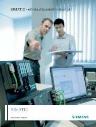
Figure 4<br />
Relevant circuits when a current, which was orig<strong>in</strong>ally flow<strong>in</strong>g through V11 and<br />
V12, is quenched. Due to the currents produced (i C1 for the one half-bridge and i C2<br />
for the other), the full load current I d commutates first to the quench<strong>in</strong>g capacitor<br />
paths. The load current then recharges quench<strong>in</strong>g capacitors C1 and C2 and<br />
commutates to capacitor C3 or the voltage limiter SBG when the voltage is high<br />
enough. The load current I d is then reduced to zero as a result of the difference<br />
between the voltage at C3 and the source voltage U q .<br />
9. Quench<strong>in</strong>g process<br />
The quench<strong>in</strong>g process for the polarity of motor voltage and load current I d (motor current)<br />
shown <strong>in</strong> Figure 3 is described below. The circuit must <strong>in</strong>clude quench<strong>in</strong>g capacitors C1 and<br />
C2 as shown <strong>in</strong> Figure 3. To illustrate this quench<strong>in</strong>g process more clearly, Figure 4 shows<br />
the circuits which are relevant for current flow <strong>in</strong> V11 and V12.<br />
When the quench<strong>in</strong>g thyristors V31, V39, V33 and V40 are fired by trigger unit ALE, the<br />
currents commutate from both the upper half-bridge V11, V13, V15 to capacitor C1 and the<br />
lower half-bridge V14, V16, V12 to capacitor C2. All currents <strong>in</strong> the converter operat<strong>in</strong>g <strong>in</strong><br />
regenerative feedback mode (V11, ..., V16) are quenched immediately. The motor voltage<br />
polarity is reversed briefly by the quench<strong>in</strong>g process.<br />
At the same time as the quench<strong>in</strong>g pulses (fir<strong>in</strong>g pulses for quench<strong>in</strong>g thyristors) are output,<br />
the fir<strong>in</strong>g pulses for the bridge SRB are disabled.<br />
Version vom 5.10.<strong>2006</strong> Seite 14 von 17 Wöhrer, Hofmüller, Himmelstoss