M-S Quad Driver X12.017 - Guy Carpenter
M-S Quad Driver X12.017 - Guy Carpenter
M-S Quad Driver X12.017 - Guy Carpenter

You also want an ePaper? Increase the reach of your titles
YUMPU automatically turns print PDFs into web optimized ePapers that Google loves.
6 M-S <strong>Quad</strong> <strong>Driver</strong> <strong>X12.017</strong> <strong>X12.017</strong>.03.SP.E<br />
Functional Description<br />
- The rising edge of the f(scx) input signal moves the<br />
rotor by one microstep.<br />
- The input signal "CW/CCW" (clockwise / counterclockwise)<br />
controls the direction of rotation of the<br />
motor.<br />
- The input signal "RESET" at low resets the output<br />
driver sequence to position 1.<br />
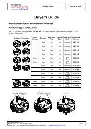
Rotor Positions<br />
Position of the rotor after a RESET<br />
21<br />
20<br />
19<br />
18<br />
23<br />
22<br />
24<br />
1 2 3<br />
4<br />
17<br />
16<br />
10<br />
15 11<br />
14 12<br />
13<br />
Input Glitch Filter & Level Shifter<br />
5<br />
6<br />
7<br />
8<br />
9<br />
Fig. 7<br />
All logic inputs of the M-S <strong>Quad</strong> <strong>Driver</strong> are armed with<br />
a glitch filter to avoid erroneous information due to<br />
spikes and glitches on the input signal lines. All<br />
negative or positive pulses of less than 20 ns width<br />
are ignored.<br />
A minimum signal pulse width (positive or negative) of<br />
450 ns guarantees correct function over the full<br />
temperature range.<br />
All logic inputs also feature a level shifter, which<br />
allows for operation of the circuit at a higher supply<br />
voltage (V DD) than the circuits driving the inputs. This<br />
is in order to drive the M-S motors at a higher torque<br />
level.<br />
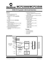
M-S Stepping Modes<br />
Full step<br />
180° Partial<br />
step<br />
60°<br />
1<br />
a division of Microcomponents SA<br />
Schützengasse 32 | CH-2540 Grenchen<br />
A COMPANY OF THE<br />
Microsteps<br />
15°<br />
Coil<br />
Coil<br />
1 2<br />
2 3<br />
The Output <strong>Driver</strong><br />
4<br />
Gear reduction<br />
1/180<br />
Full step = 1°<br />
Partial step = 1/3°<br />
Microstep = 1/12°<br />
Fig. 8<br />
The output driver converts the pulse train of f(scx) into<br />
a current level sequence sent to the two motor coils of<br />
the M-S. This sequence of 24 current levels per rotor<br />
revolution is used to produce the microstepping<br />
movement of the rotor.<br />
A microstep is an angular rotation of 1/12 deg. of the<br />
M-S shaft or 15 deg. on the rotor shaft.<br />
A partial step is an angular rotation of 1/3 deg. of the<br />
M-S shaft or 60 deg. on the rotor shaft.<br />
A full step is an angular rotation of 1 deg. of the M-S<br />
shaft or 180 deg. on the rotor shaft.<br />
The microstepping allows for smooth and appealing<br />
movement of a pointer if the M-S is used as pointer<br />
drive. It is not intended as a precise positioning. The<br />
precision of the angular position is given by the<br />
resolution of the partial step.