M-S Quad Driver X12.017 - Guy Carpenter
M-S Quad Driver X12.017 - Guy Carpenter
M-S Quad Driver X12.017 - Guy Carpenter

Create successful ePaper yourself
Turn your PDF publications into a flip-book with our unique Google optimized e-Paper software.
<strong>X12.017</strong>.03.SP.E M-S <strong>Quad</strong> <strong>Driver</strong> <strong>X12.017</strong> 1<br />
Features<br />
- generates microsteps<br />
- glitch filters on all inputs<br />
- VDD = 4.5 to 5.5V<br />
- low EMI emission<br />
Description<br />
M-S <strong>Quad</strong> <strong>Driver</strong> <strong>X12.017</strong><br />
The M-S <strong>Quad</strong> <strong>Driver</strong> <strong>X12.017</strong> is a monolithic CMOS<br />
device intended to be used as an interface circuit to<br />
ease the use of the Miniature Stepper Motors M-S<br />
X15.xxx. It was specifically designed for applications<br />
in the car dashboard. The circuit allows the user to<br />
drive four motors as it contains four identical drivers<br />
on the same chip.<br />
The driver circuit converts a pulse train f(scx) into a<br />
current level sequence sent to the motor coils. This<br />
sequence is used to produce the microstepping<br />
movement of the motor. A microstep corresponds to<br />
an angular rotation of 1/12 deg. of the shaft. The<br />
microstepping allows for smooth and appealing<br />
movement of a pointer if the M-S is used as pointer<br />
drive. Note that the precision of the angular position is<br />
always affected by the gear play of the motor which is<br />
±1/3 deg.<br />
Applications<br />
Analogue Instrumentation<br />
- car dashboard (Hybrid Instrument Cluster)<br />
- nautical instrumentation<br />
- aeronautical instrumentation<br />
Microrobotics<br />
- appliance controls<br />
- devices for medical analysis<br />
Typical Operating Configuration<br />
Control bus<br />
a division of Microcomponents SA<br />
Schützengasse 32 | CH-2540 Grenchen<br />
A COMPANY OF THE<br />
System µ-processor<br />
RESET<br />
f(scx) A<br />
CW/CCW A<br />
f(scx) B<br />
CW/CCW B<br />
f(scx) C<br />
CW/CCW C<br />
f(scx) D<br />
CW/CCW D<br />
Pin Assignment<br />
VDD<br />
CW/CCW B<br />
f(scx) B<br />
OUT 3A<br />
OUT 4A<br />
OUT 2A<br />
OUT 1A<br />
OUT 1D<br />
OUT 2D<br />
OUT 4D<br />
OUT 3D<br />
VSS<br />
CW/CCW C<br />
f(scx) C<br />
1<br />
2<br />
3<br />
4<br />
5<br />
6<br />
7<br />
8<br />
9<br />
10<br />
11<br />
12<br />
13<br />
14<br />
M-S <strong>X12.017</strong><br />
M-S <strong>Quad</strong> <strong>Driver</strong> <strong>X12.017</strong><br />
28<br />
27<br />
26<br />
25<br />
24<br />
23<br />
22<br />
21<br />
20<br />
19<br />
18<br />
17<br />
16<br />
15<br />
OUT<br />
A<br />
OUT<br />
B<br />
OUT<br />
C<br />
OUT<br />
D<br />
M-S<br />
M-S<br />
M-S<br />
M-S<br />
f(scx) A<br />
CW/CCW A<br />
RESET<br />
OUT 3B<br />
OUT 4B<br />
OUT 2B<br />
OUT 1B<br />
OUT 1C<br />
OUT 2C<br />
OUT 4C<br />
OUT 3C<br />
f(scx) D<br />
CW/CCW D<br />
VDD<br />
Fig. 1<br />
Fig. 2
2 M-S <strong>Quad</strong> <strong>Driver</strong> <strong>X12.017</strong> <strong>X12.017</strong>.03.SP.E<br />
Absolute Maximum Ratings<br />
Parameter Symbol Conditions<br />
Voltage V DD to V SS V DD -0.3 to +6V<br />
Voltage at any pin to V DD V MAX +0.3V<br />
Voltage at any pin to V SS V MIN -0.3V<br />
Current at OUTs 1-4 I OUTMAX ±35mA<br />
Max. junction temperature T j 150°C<br />
Operating temp. range T A -40 to +105°C<br />
Storage temp. range T STO -65 to +125°C<br />
Table 1<br />
Stresses beyond these listed maximum ratings may<br />
cause permanent damage to the device. Exposure to<br />
conditions beyond specified operating conditions may<br />
affect device reliability or cause malfunction.<br />
Operating Conditions<br />
Handling Procedures<br />
The device has built-in protection against high static<br />
voltages or electric fields; however, anti-static<br />
precautions must be taken as for any other CMOS<br />
component.<br />
Unless otherwise specified, proper operation can only<br />
occur when all terminal voltages are kept within the<br />
supply voltage range.<br />
Unused inputs must always be tied to a defined logic<br />
voltage level unless otherwise specified.<br />
Parameter Symbol Test Conditions Min Typ Max Units<br />
Operating temperature T A -40 +105 °C<br />
Thermal impedance R th j-a DIP package 60 °C/W<br />
SO package 80 °C/W<br />
Supply voltage V DD 4.5 5 5.5 V<br />
Input voltage at any pin V IN V SS V DD V<br />
Table 2<br />
Load Characteristics<br />
Parameter Symbol Test Conditions Min Typ Max Units<br />
Coil resistance R B25 M-S X15.xxx, T A=25°C 260 290 320 Ω<br />
R B-40 M-S X15.xxx, T A=-40°C 190 Ω<br />
R B105 M-S X15.xxx, T A=105°C 340 Ω<br />
Phase inductance L 25 M-S X15.xxx, T A=25°C 0.4 H<br />
Table 3<br />
Electrical Characteristics<br />
V DD = 4.5 ÷ 5.5V, T A = -40 ÷105°C, unless otherwise specified<br />
Parameter Symbol Test Conditions Min Typ Max Units<br />
Power Consumption<br />
Typical supply current IC VDD=5V, ω=200°/s,<br />
TA=25°C, RB25=290Ω 76 mA<br />
Worst case supply current ICMAX VDD=5.5V, RESET=VSS, TA=-40°C, RB-40=190Ω 200 mA<br />
Quiescent supply current<br />
Inputs<br />
ICC All inputs at VDD or VSS, no<br />
load<br />
300 µA<br />
Low level input voltage VIL VDD = 4.5 ÷ 5.5V VSS 1.35 V<br />
High level input voltage VIH VDD = 4.5 ÷ 5.5V 3.15 VDD V<br />
Input leakage IIN VIN = VSS or VDD -10 10 µA<br />
Table 4<br />
a division of Microcomponents SA<br />
Schützengasse 32 | CH-2540 Grenchen<br />
A COMPANY OF THE
<strong>X12.017</strong>.03.SP.E M-S <strong>Quad</strong> <strong>Driver</strong> <strong>X12.017</strong> 3<br />
Timing Characteristics<br />
V DD = 4.5 ÷ 5.5V, T A = -40 ÷105°C, t rise and t fall ≤ 20ns, input signal swing V SS to V DD<br />
Parameter Symbol Test Conditions Min Typ Max Units<br />
Signal pulse width t w high or low 450 ns<br />
Input frequency f(scx) <strong>Driver</strong> input limit 1.1 MHz<br />
Motor speed limit (ω=600°/s) 7.2 kHz<br />
Setup time to f(scx) t s high or low 100 ns<br />
RESET release time to f(scx) t rr 100 ns<br />
Table 5<br />
Delay Timing Waveforms<br />
Any signal<br />
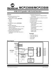
Pin Description<br />
tw<br />
CW/CCW<br />
f(scx)<br />
ts<br />
a division of Microcomponents SA<br />
Schützengasse 32 | CH-2540 Grenchen<br />
A COMPANY OF THE<br />
RESET<br />
f(scx)<br />
Unused inputs must always be tied to a defined logic voltage level unless otherwise specified<br />
Pin Number<br />
DIP/SOL 28 Version<br />
Name I/O Function<br />
1 / 15 VDD V Positive supply voltage<br />
12 VSS V Negative supply voltage<br />
28 / 3 / 14 / 17 f(scx) A / B / C / D I Stepping frequency; <strong>Driver</strong> A / B / C / D<br />
27 / 2 / 13 / 16 CW/CCW A / B / C / D I Direction of rotation; <strong>Driver</strong> A / B / C / D<br />
26 RESET I Reset for the four drivers<br />
7 / 22 / 21 / 8 OUT 1A / 1B / 1C / 1D O Coil output 1; <strong>Driver</strong> A / B / C / D<br />
6 / 23 / 20 / 9 OUT 2A / 2B / 2C / 2D O Coil output 2; <strong>Driver</strong> A / B / C / D<br />
4 / 25 / 18 / 11 OUT 3A / 3B / 3C / 3D O Coil output 3; <strong>Driver</strong> A / B / C / D<br />
5 / 24 / 19 / 10 OUT 4A / 4B / 4C / 4D O Coil output 4; <strong>Driver</strong> A / B / C / D<br />
Circuit Protections<br />
To filter fast voltage transients, it is highly<br />
recommended to connect two 100nF ceramic<br />
capacitors to the power supply pins, one on either side<br />
and as close as possible to the IC.<br />
Moreover, to protect the IC against latch-up, a 5μF<br />
capacitor per motor connected should be added.<br />
Thus, for 4 motors, typically a 22μF capacitor must be<br />
used, either electrolytic or tantalum. Note this<br />
capacitor can be placed close to the voltage regulator.<br />
Recommended Power Up<br />
trr<br />
Fig.3<br />
Table 6<br />
In order to power up the circuit in a defined manner, it<br />
is recommended to keep the RESET input low while<br />
the VDD voltage is raising. After a delay of about 1ms,<br />
the RESET can be released (i.e. set high).<br />
Depending on the microcontroller used, an external<br />
pull-down resistor might be required to properly set the<br />
RESET state at low during the start-up.
4 M-S <strong>Quad</strong> <strong>Driver</strong> <strong>X12.017</strong> <strong>X12.017</strong>.03.SP.E<br />
Block Diagram<br />
f(scx) A<br />
G/L = Glitch filter & Level Shifter<br />
G/L<br />
CW/CCW A G/L<br />
RESET G/L<br />
f(scx) B<br />
CW/CCW B<br />
f(scx) C<br />
CW/CCW C<br />
f(scx) D<br />
CW/CCW D<br />
G/L<br />
G/L<br />
G/L<br />
G/L<br />
G/L<br />
G/L<br />
OUTPUT<br />
DRIVER<br />
A<br />
OUTPUT<br />
DRIVER<br />
B<br />
OUTPUT<br />
DRIVER<br />
C<br />
OUTPUT<br />
DRIVER<br />
D<br />
a division of Microcomponents SA<br />
Schützengasse 32 | CH-2540 Grenchen<br />
A COMPANY OF THE<br />
OUT A1<br />
COIL A1<br />
OUT A2<br />
OUT A3<br />
COIL A2<br />
OUT A4<br />
OUT B1<br />
COIL B1<br />
OUT B2<br />
OUT B3<br />
COIL B2<br />
OUT B4<br />
OUT C1<br />
COIL C1<br />
OUT C2<br />
OUT C3<br />
COIL C2<br />
OUT C4<br />
OUT D1<br />
COIL D1<br />
OUT D2<br />
OUT D3<br />
COIL D2<br />
OUT D4<br />
Fig. 4
<strong>X12.017</strong>.03.SP.E M-S <strong>Quad</strong> <strong>Driver</strong> <strong>X12.017</strong> 5<br />
Suggested Applications<br />
VCC<br />
18<br />
VDD<br />
µC<br />
VSS<br />
19<br />
GND<br />
VCC<br />
18<br />
VDD<br />
µC<br />
VSS<br />
19<br />
GND<br />
OUT<br />
OUT<br />
OUT<br />
OUT<br />
OUT<br />
OUT<br />
OUT<br />
OUT<br />
OUT<br />
OUT<br />
OUT<br />
OUT<br />
OUT<br />
OUT<br />
OUT<br />
9<br />
10<br />
11<br />
12<br />
13<br />
14<br />
15<br />
16<br />
17<br />
VCC<br />
+<br />
22µF<br />
Note: depending on the µC used, this external<br />
pull-down resistor might be required to properly set<br />
the RESET state at low during the start-up.<br />
9<br />
11<br />
13<br />
15<br />
16<br />
17<br />
Caution : the 100nF ceramic capacitors must be placed as close as possible to the driver<br />
100nF 100nF<br />
GND GND<br />
GND<br />
1<br />
2<br />
VCC<br />
+<br />
GND<br />
22µF<br />
Note: depending on the µC used, this external<br />
pull-down resistor might be required to properly set<br />
the RESET state at low during the start-up.<br />
10k<br />
28<br />
27<br />
3<br />
2<br />
14<br />
13<br />
17<br />
16<br />
26<br />
28<br />
27<br />
3<br />
2<br />
GND<br />
14<br />
13<br />
17<br />
16<br />
26<br />
1<br />
VDD<br />
Fscx A OUT1 A<br />
CW/CCW* A OUT2 A<br />
OUT3 A<br />
OUT4 A<br />
Fscx B OUT1 B<br />
CW/CCW* B OUT2 B<br />
OUT3 B<br />
OUT4 B<br />
Fscx C OUT1 C<br />
CW/CCW* C OUT2 C<br />
OUT3 C<br />
OUT4 C<br />
Fscx D OUT1 D<br />
CW/CCW* D OUT2 D<br />
OUT3 D<br />
OUT4 D<br />
RESET*<br />
1<br />
VDD<br />
VSS<br />
12<br />
GND<br />
15<br />
VDD<br />
a division of Microcomponents SA<br />
Schützengasse 32 | CH-2540 Grenchen<br />
A COMPANY OF THE<br />
MS <strong>X12.017</strong><br />
Fscx A OUT1 A<br />
CW/CCW* A OUT2 A<br />
OUT3 A<br />
OUT4 A<br />
Fscx B OUT1 B<br />
CW/CCW* B OUT2 B<br />
OUT3 B<br />
OUT4 B<br />
Fscx C OUT1 C<br />
CW/CCW* C OUT2 C<br />
OUT3 C<br />
OUT4 C<br />
Fscx D OUT1 D<br />
CW/CCW* D OUT2 D<br />
OUT3 D<br />
OUT4 D<br />
RESET*<br />
VSS<br />
12<br />
GND<br />
15<br />
VDD<br />
MS <strong>X12.017</strong><br />
7<br />
6<br />
4<br />
5<br />
22<br />
23<br />
25<br />
24<br />
21<br />
20<br />
18<br />
19<br />
8<br />
9<br />
11<br />
10<br />
100nF 100nF<br />
GND GND<br />
GND<br />
1<br />
2<br />
7<br />
6<br />
4<br />
5<br />
22<br />
23<br />
25<br />
24<br />
21<br />
20<br />
18<br />
19<br />
8<br />
9<br />
11<br />
10<br />
3<br />
4<br />
1<br />
2<br />
3<br />
4<br />
1<br />
2<br />
3<br />
4<br />
1<br />
2<br />
3<br />
4<br />
3<br />
4<br />
1<br />
2<br />
3<br />
4<br />
1<br />
2<br />
3<br />
4<br />
X15.xxx<br />
X15.xxx<br />
X15.xxx<br />
X15.xxx<br />
Caution : the 100nF ceramic capacitors must be placed as close as possible to the driver<br />
GND<br />
10k<br />
X15.xxx<br />
X15.xxx<br />
X15.xxx<br />
Fig. 5<br />
Fig. 6
6 M-S <strong>Quad</strong> <strong>Driver</strong> <strong>X12.017</strong> <strong>X12.017</strong>.03.SP.E<br />
Functional Description<br />
- The rising edge of the f(scx) input signal moves the<br />
rotor by one microstep.<br />
- The input signal "CW/CCW" (clockwise / counterclockwise)<br />
controls the direction of rotation of the<br />
motor.<br />
- The input signal "RESET" at low resets the output<br />
driver sequence to position 1.<br />
Rotor Positions<br />
Position of the rotor after a RESET<br />
21<br />
20<br />
19<br />
18<br />
23<br />
22<br />
24<br />
1 2 3<br />
4<br />
17<br />
16<br />
10<br />
15 11<br />
14 12<br />
13<br />
Input Glitch Filter & Level Shifter<br />
5<br />
6<br />
7<br />
8<br />
9<br />
Fig. 7<br />
All logic inputs of the M-S <strong>Quad</strong> <strong>Driver</strong> are armed with<br />
a glitch filter to avoid erroneous information due to<br />
spikes and glitches on the input signal lines. All<br />
negative or positive pulses of less than 20 ns width<br />
are ignored.<br />
A minimum signal pulse width (positive or negative) of<br />
450 ns guarantees correct function over the full<br />
temperature range.<br />
All logic inputs also feature a level shifter, which<br />
allows for operation of the circuit at a higher supply<br />
voltage (V DD) than the circuits driving the inputs. This<br />
is in order to drive the M-S motors at a higher torque<br />
level.<br />
M-S Stepping Modes<br />
Full step<br />
180° Partial<br />
step<br />
60°<br />
1<br />
a division of Microcomponents SA<br />
Schützengasse 32 | CH-2540 Grenchen<br />
A COMPANY OF THE<br />
Microsteps<br />
15°<br />
Coil<br />
Coil<br />
1 2<br />
2 3<br />
The Output <strong>Driver</strong><br />
4<br />
Gear reduction<br />
1/180<br />
Full step = 1°<br />
Partial step = 1/3°<br />
Microstep = 1/12°<br />
Fig. 8<br />
The output driver converts the pulse train of f(scx) into<br />
a current level sequence sent to the two motor coils of<br />
the M-S. This sequence of 24 current levels per rotor<br />
revolution is used to produce the microstepping<br />
movement of the rotor.<br />
A microstep is an angular rotation of 1/12 deg. of the<br />
M-S shaft or 15 deg. on the rotor shaft.<br />
A partial step is an angular rotation of 1/3 deg. of the<br />
M-S shaft or 60 deg. on the rotor shaft.<br />
A full step is an angular rotation of 1 deg. of the M-S<br />
shaft or 180 deg. on the rotor shaft.<br />
The microstepping allows for smooth and appealing<br />
movement of a pointer if the M-S is used as pointer<br />
drive. It is not intended as a precise positioning. The<br />
precision of the angular position is given by the<br />
resolution of the partial step.
<strong>X12.017</strong>.03.SP.E M-S <strong>Quad</strong> <strong>Driver</strong> <strong>X12.017</strong> 7<br />
Dimensions of DIP Package<br />
28-pin plastic DIP<br />
D<br />
C<br />
0 - 15°<br />
Dimensions of SOL Package<br />
28-pin plastic SOL<br />
0 - 8°<br />
E<br />
D<br />
E<br />
C<br />
Ordering Information<br />
J<br />
A<br />
F G<br />
A<br />
F G<br />
The M-S <strong>Quad</strong> <strong>Driver</strong> <strong>X12.017</strong> is available in the following packages:<br />
- DIP 28-pin plastic package M-S <strong>Quad</strong> <strong>Driver</strong> <strong>X12.017</strong> - DIP28<br />
- SOL 28-pin wide plastic package M-S <strong>Quad</strong> <strong>Driver</strong> <strong>X12.017</strong> - SOL28<br />
Chip form on request.<br />
When ordering, please specify the complete part number and package.<br />
H<br />
B<br />
H<br />
I<br />
J<br />
B<br />
a division of Microcomponents SA<br />
Schützengasse 32 | CH-2540 Grenchen<br />
A COMPANY OF THE<br />
I<br />
A<br />
B<br />
C<br />
D<br />
E<br />
F<br />
G<br />
H<br />
I<br />
J<br />
A<br />
B<br />
C<br />
D<br />
E<br />
F<br />
G<br />
H<br />
I<br />
J<br />
Inches mm<br />
Min Max Min Max<br />
1.445 1.455 36.70 36.96<br />
0.530 0.550 13.46 13.97<br />
0.600 0.625 15.24 15.88<br />
0.008 0.012 0.20 0.30<br />
0.070 0.080 1.78 2.03<br />
0.015 0.022 0.38 0.56<br />
0.100 BSC 2.54 BSC<br />
0.015 - 0.38 -<br />
- 0.190 - 4.83<br />
0.125 0.135 3.18 3.43<br />
Fig. 9<br />
Inches mm<br />
Min Max Min Max<br />
0.701 0.711 17.81 18.06<br />
0.292 0.299 7.42 7.59<br />
0.400 0.410 10.16 10.41<br />
0.009 0.013 0.23 0.32<br />
0.010 0.016 0.25 0.41<br />
0.014 0.019 0.35 0.48<br />
0.050 BSC 1.27 BSC<br />
0.005 0.012 0.12 0.29<br />
0.097 0.104 2.46 2.64<br />
0.024 0.040 0.61 1.02<br />
Fig. 10
8 M-S <strong>Quad</strong> <strong>Driver</strong> <strong>X12.017</strong> <strong>X12.017</strong>.03.SP.E<br />
Table of Contents<br />
M-S <strong>Quad</strong> <strong>Driver</strong> <strong>X12.017</strong> .......................................... 1<br />
Features ................................................................ 1<br />
Description ............................................................ 1<br />
Applications ........................................................... 1<br />
Typical Operating Configuration............................ 1<br />
Pin Assignment ..................................................... 1<br />
Absolute Maximum Ratings................................... 2<br />
Handling Procedures............................................. 2<br />
Operating Conditions............................................. 2<br />
Load Characteristics.............................................. 2<br />
Electrical Characteristics....................................... 2<br />
Timing Characteristics........................................... 3<br />
Delay Timing Waveforms...................................... 3<br />
Pin Description .......................................................3<br />
Circuit Protections ..................................................3<br />
Recommended Power Up......................................3<br />
Block Diagram........................................................4<br />
Suggested Applications..........................................5<br />
Functional Description............................................6<br />
Rotor Positions.......................................................6<br />
Input Glitch Filter & Level Shifter............................6<br />
M-S Stepping Modes..............................................6<br />
The Output <strong>Driver</strong>...................................................6<br />
Dimensions of DIP Package ..................................7<br />
Dimensions of SOL Package .................................7<br />
Ordering Information ..............................................7<br />
The information and specifications given here are correct and valid to the best of our knowledge. However<br />
switec switec assumes no liability for damages which may arise through the incorrect use of this information or<br />
for eventual damages to existing patents or to the rights of third parties. The general purchase conditions for<br />
electrical and mechanical products of switec switec apply to all commercial transactions.<br />
switec switec reserves the right to make changes in the products contained in this document in order to improve<br />
design or performance and to supply the best possible products.<br />
switec switec is a trade mark of the Swatch Group Management Services AG.<br />
© switec a division of Microcomponents SA 2001 SR-10.07.01<br />
a division of Microcomponents SA<br />
Schützengasse 32 | CH-2540 Grenchen<br />
A COMPANY OF THE