Create successful ePaper yourself
Turn your PDF publications into a flip-book with our unique Google optimized e-Paper software.
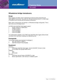
CAN/GPS/Power Connections<br />
The supplied terminal adapter plug (DE9 male to 9-way terminal block) provides convenient screw terminal connections to<br />
the CAN/GPS/POWER connector. Alternatively, a custom cable can be made up using a conventional DE9 plug.<br />
A typical wiring configuration is shown below:<br />
Vehicle<br />
Diagnostic<br />
Connector<br />
(SAE J1962)<br />
1<br />
J1850+ – 2<br />
3<br />
CHAS GND – 4<br />
SIG GND – 5<br />
CAN HI – 6<br />
ISO 9141 K – 7<br />
8<br />
9<br />
J1850- – 10<br />
11<br />
12<br />
13<br />
CAN LO – 14<br />
ISO 9141 L – 15<br />
BATTERY – 16<br />
1 – 5V out<br />
2 – GND<br />
3 – CAN1 HI<br />
4 – GPS RXD<br />
5 – CAN1 LO<br />
6 – CAN2 HI<br />
7 – CAN2 LO<br />
8 – GPS TXD<br />
9 – POWER<br />
DE9 male<br />
<strong>CANgate</strong><br />
SAE J1962 male<br />
GPS<br />
RXD<br />
TXD<br />
GND<br />
Power<br />
Connector to suit<br />
GPS unit<br />
Diagnostic connector and GPS wiring diagram<br />
Note A vehicle with an SAE J1962 diagnostic connector may not necessarily use a CAN network. If CAN is not used then the<br />
indicated pins will either be not connected or in some applications may have a different function. Ensure that the vehicle does<br />
actually use high speed CAN before connecting <strong>CANgate</strong> to the diagnostic connector.<br />
CAN Bus Type and Termination<br />
The CAN protocol can operate over a number of different physical layers. A physical layer is a specification defining the low<br />
level electrical characteristics of the network, eg. allowable bit rates, voltage levels, cable type and so on.<br />
It is important to note that <strong>CANgate</strong> only supports the high speed CAN physical layer, as defined in ISO 11898-2 / SAE<br />
J2284. This is by far the most widely used physical layer. The important characteristics of this standard are:<br />
two wire, 5V differential signalling<br />
bit rate 10kbps – 1Mbps<br />
twisted pair cable, 120 Ω characteristic impedance<br />
A high speed CAN network is required to have a linear topology. There is a single twisted pair "backbone" cable which can<br />
be up to 40m long. Electronic control units (ECUs) are then connected to the bus using short stub connections (max length<br />
0.3m). (These limits are for 1Mbps operation and can be increased somewhat for lower bit rates.)<br />
At each end of the bus, correct termination is required. This typically consists of a resistor (wired across the two bus lines)<br />
that matches the impedance of the cable (ie. 120 Ω). The termination resistance provides the correct DC load for the CAN<br />
output drivers, and minimises signal "reflections", which can distort the CAN signals and cause errors.<br />
UM-0086-A2 <strong>CANgate</strong> User’s <strong>Manual</strong> Page 9