
Create successful ePaper yourself
Turn your PDF publications into a flip-book with our unique Google optimized e-Paper software.
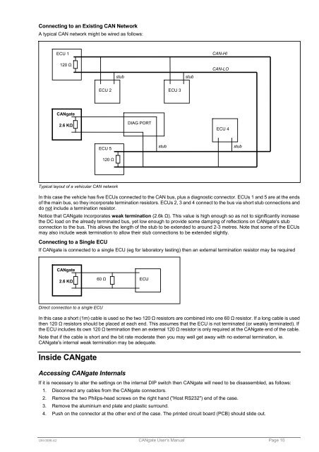
Connecting to an Existing CAN Network<br />
A typical CAN network might be wired as follows:<br />
ECU 1<br />
120 Ω<br />
stub<br />
stub<br />
CAN-HI<br />
CAN-LO<br />
ECU 2 ECU 3<br />
<strong>CANgate</strong><br />
2.6 KΩ<br />
DIAG PORT<br />
ECU 4<br />
ECU 5<br />
stub<br />
stub<br />
120 Ω<br />
Typical layout of a vehicular CAN network<br />
In this case the vehicle has five ECUs connected to the CAN bus, plus a diagnostic connector. ECUs 1 and 5 are at the ends<br />
of the main bus, so they incorporate termination resistors. ECUs 2, 3 and 4 connect to the bus via short stub connections and<br />
do not include a termination resistor.<br />
Notice that <strong>CANgate</strong> incorporates weak termination (2.6k Ω). This value is high enough so as not to significantly increase<br />
the DC load on the already terminated bus, yet low enough to provide some damping of reflections on <strong>CANgate</strong>'s stub<br />
connection to the bus. This allows the length of the stub to be extended to around 2-3 metres. Note that some of the ECUs<br />
may also include weak termination to allow their stub connections to be extended slightly.<br />
Connecting to a Single ECU<br />
If <strong>CANgate</strong> is connected to a single ECU (eg for laboratory testing) then an external termination resistor may be required<br />
<strong>CANgate</strong><br />
2.6 KΩ<br />
60 Ω<br />
ECU<br />
Direct connection to a single ECU<br />
In this case a short (1m) cable is used so the two 120 Ω resistors are combined into one 60 Ω resistor. If a long cable is used<br />
then 120 Ω resistors should be placed at each end. This assumes that the ECU is not terminated (or weakly terminated). If<br />
the ECU includes its own 120 Ω termination then an external 120 Ω resistor is only required at the <strong>CANgate</strong> end of the cable.<br />
Note that if the cable is short and the bit rate moderate then you may well get away with no external termination, ie.<br />
<strong>CANgate</strong>'s internal weak termination may be adequate.<br />
Inside <strong>CANgate</strong><br />
Accessing <strong>CANgate</strong> Internals<br />
If it is necessary to alter the settings on the internal DIP switch then <strong>CANgate</strong> will need to be disassembled, as follows:<br />
1. Disconnect any cables from the <strong>CANgate</strong> connectors.<br />
2. Remove the two Philips-head screws on the right hand ("Host RS232") end of the case.<br />
3. Remove the aluminium end plate and plastic surround.<br />
4. Push on the connector at the other end of the case. The printed circuit board (PCB) should slide out.<br />
UM-0086-A2 <strong>CANgate</strong> User’s <strong>Manual</strong> Page 10