Create successful ePaper yourself
Turn your PDF publications into a flip-book with our unique Google optimized e-Paper software.
Druckaufbau− und Entlüftungs<br />
ventil<br />
Soft start/quick exhaust valve<br />
MS6(N)−<strong>SV</strong><br />
(de) Bedienungs−<br />
anleitung<br />
(en) Operating<br />
instructions<br />
743 267<br />
0904a
MS6(N)−<strong>SV</strong><br />
Symbole/Symbols:<br />
Warnung<br />
Warning, Caution<br />
Einbau und Inbetriebnahme nur von qualifi<br />
ziertem Fachpersonal, gemäß Bedienungs<br />
anleitung.<br />
Fitting and commissioning to be carried out<br />
by qualified personnel only in accordance<br />
with the operating instructions.<br />
Hinweis<br />
Please note<br />
Umwelt<br />
Antipollution<br />
Zubehör<br />
Accessories<br />
Deutsch . . . . . . . . . . . . . . . . . . . . . . . . . . . . . . . . . . . . . . . . . . . . . . . . . . . . . . . . . . . . . . . . . . . 3<br />
English . . . . . . . . . . . . . . . . . . . . . . . . . . . . . . . . . . . . . . . . . . . . . . . . . . . . . . . . . . . . . . . . . . . . 35<br />
2<br />
<strong>Festo</strong> MS6(N)−<strong>SV</strong> 0904a
MS6(N)−<strong>SV</strong><br />
Druckaufbau− und Entlüftungsventil MS6(N)−<strong>SV</strong>Deutsch<br />
Inhaltsverzeichnis<br />
1 Bedienteile und Anschlüsse . . . . . . . . . . . . . . . . . . . . . . . . . . . . . . . . . . . . 4<br />
2 Funktion und Anwendung . . . . . . . . . . . . . . . . . . . . . . . . . . . . . . . . . . . . . . 5<br />
3 Voraussetzungen für den Produkteinsatz . . . . . . . . . . . . . . . . . . . . . . . . . 6<br />
4 Einbau mechanisch/pneumatisch . . . . . . . . . . . . . . . . . . . . . . . . . . . . . . . 8<br />
Mechanisch . . . . . . . . . . . . . . . . . . . . . . . . . . . . . . . . . . . . . . . . . . . . . . . . . . 8<br />
Pneumatisch Anschluss 1 und 2 (Gewindegröße G½ oder NPT½−14) . 10<br />
Pneumatisch Anschluss 3 (Gewindegröße G1 oder NPT1) . . . . . . . . . . . 10<br />
5 Elektrischer Anschluss . . . . . . . . . . . . . . . . . . . . . . . . . . . . . . . . . . . . . . . . 11<br />
6 Anschlussbeispiele (elektrisch) . . . . . . . . . . . . . . . . . . . . . . . . . . . . . . . . . 13<br />
MS6(N)−<strong>SV</strong> mit Multipol−Steckdose NECA−S1G9−P9−MP1 . . . . . . . . . . . . . 14<br />
MS6(N)−<strong>SV</strong> mit Multipol−Steckdose NECA−S1G9−P9−MP3 . . . . . . . . . . . . . 16<br />
Betriebsarten Automatischer Start/Überwachter Start . . . . . . . . . . . . . . . 17<br />
Meldekontakte 13/14 . . . . . . . . . . . . . . . . . . . . . . . . . . . . . . . . . . . . . . . . . . 19<br />
7 Inbetriebnahme . . . . . . . . . . . . . . . . . . . . . . . . . . . . . . . . . . . . . . . . . . . . . . 20<br />
8 Betrieb . . . . . . . . . . . . . . . . . . . . . . . . . . . . . . . . . . . . . . . . . . . . . . . . . . . . . . 25<br />
9 Wartung und Pflege . . . . . . . . . . . . . . . . . . . . . . . . . . . . . . . . . . . . . . . . . . . 25<br />
10 Ausbau . . . . . . . . . . . . . . . . . . . . . . . . . . . . . . . . . . . . . . . . . . . . . . . . . . . . . . 25<br />
11 Außerbetriebnahme und Entsorgung . . . . . . . . . . . . . . . . . . . . . . . . . . . . . 26<br />
12 Zubehör . . . . . . . . . . . . . . . . . . . . . . . . . . . . . . . . . . . . . . . . . . . . . . . . . . . . . 26<br />
13 Diagnose und Fehlerbehandlung . . . . . . . . . . . . . . . . . . . . . . . . . . . . . . . . 27<br />
LED−Anzeige . . . . . . . . . . . . . . . . . . . . . . . . . . . . . . . . . . . . . . . . . . . . . . . . . . 27<br />
Fehlercode . . . . . . . . . . . . . . . . . . . . . . . . . . . . . . . . . . . . . . . . . . . . . . . . . . . 27<br />
14 Technische Daten . . . . . . . . . . . . . . . . . . . . . . . . . . . . . . . . . . . . . . . . . . . . . 29<br />
<strong>Festo</strong> MS6(N)−<strong>SV</strong> 0904a Deutsch<br />
3
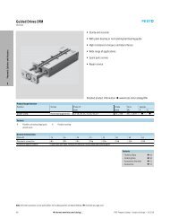
MS6(N)−<strong>SV</strong><br />
1 Bedienteile und Anschlüsse<br />
Druckaufbau− und Entlüftungsventil MS6(N)−<strong>SV</strong> nach DINENISO13849−1,<br />
max.erreichbarer Performance Level e", Kategorie 3 + 4.<br />
1<br />
2<br />
3<br />
9<br />
4<br />
5<br />
8<br />
6<br />
7<br />
1 LED Anzeige (LED Power und LED Er<br />
ror)<br />
2 Drosselschraube für Softstartfunk<br />
tion<br />
3 Pneumatischer Anschluss 1 (Eingang<br />
Druckluft)<br />
4 Elektronikblock<br />
6 Multipol−Steckdose NECA<br />
7 Pneumatischer Anschluss 3 (Entlüf<br />
tung)<br />
8 Anschluss Funktionserde<br />
9 Pneumatischer Anschluss 2 (Aus<br />
gang Druckluft)<br />
5 Ventilblock<br />
Bild1<br />
4<br />
<strong>Festo</strong> MS6(N)−<strong>SV</strong> 0904a Deutsch
MS6(N)−<strong>SV</strong><br />
2 Funktion und Anwendung<br />
Das elektropneumatische Druckaufbau− und Entlüftungsventil MS6(N)−<strong>SV</strong> dient<br />
bestimmungsgemäß dem schnellen und sicheren Druckabbau und dem sanften<br />
Druckaufbau in pneumatischen Leitungssystemen und Endgeräten der Industrie.<br />
Bei dem MS6(N)−<strong>SV</strong> handelt es sich um ein eigensicheres, redundantes mecha<br />
tronisches System nach den Forderungen der DINENISO13849−1, bei dem das<br />
sicherheitsgerichtete pneumatische Schutzziel, sicheres Entlüften, auch bei einem<br />
Fehler im Ventil (z.B. durch Verschleiß, Verschmutzung) gewährleistet ist.<br />
Über den elektrischen Anschluss (Multipol−Steckdose NECA Sub−D, 9−polig) erhält<br />
das MS6(N)−<strong>SV</strong> die sicheren Enable−Signale (EN1/EN2) von handelsüblichen<br />
elektronischen oder elektromechanischen Sicherheitsschaltgeräten, welche die<br />
Schutzeinrichtungen der Maschine (z.B. Not−Aus, Lichtgitter, elektrische Türschal<br />
ter der Schutzeinhausung, etc.) überwachen.<br />
Zur bestimmungsgemäßen Verwendung gehört die Einhaltung der in dieser Bedie<br />
nungsanleitung festgelegten Grenzwerte (z.B. Betriebsmedium, Drücke, Tempera<br />
turen, Betriebspannungen, Durchflüsse).<br />
Die bestimmungsgemäße Verwendung wurde von der BGIA geprüft und ist durch<br />
eine BG−Prüfbescheinigung dokumentiert.<br />
Betriebsarten<br />
Die folgenden 2 Betriebsarten sind möglich:<br />
Automatischer Start" (automatic reset)<br />
Überwachter Start" (monitored reset)<br />
In beiden Betriebsarten kann das MS6(N)−<strong>SV</strong> entweder mit statischen oder dyna<br />
mischen Enable−Signalen (EN1/EN2) angesteuert werden (è Kapitel 6 Anschluss<br />
beispiele").<br />
Hinweis<br />
Das Produkt ist ausschließlich für industrielle Zwecke geeignet.<br />
<strong>Festo</strong> MS6(N)−<strong>SV</strong> 0904a Deutsch<br />
5
MS6(N)−<strong>SV</strong><br />
3 Voraussetzungen für den Produkteinsatz<br />
Das MS6(N)−<strong>SV</strong> wurde unter sorgfältiger Anwendung der zutreffenden Normen und<br />
Richtlinien sowie der anerkannten Regeln der Technik entwickelt und gefertigt. Die<br />
Schutzfunktion des Geräts kann jedoch beeinträchtigt werden, wenn es nicht be<br />
stimmungsgemäß eingesetzt wird. In diesem Fall können Gefahren für Leib und<br />
Leben von Personen entstehen.<br />
Installation und Inbetriebnahme<br />
Die Installation und Inbetriebnahme sind nur durch geschultes Fachpersonal zuläs<br />
sig. Das MS6(N)−<strong>SV</strong> darf nur gemäß den in Kapitel 14 Technische Daten" festge<br />
legten Werten angeschlossen und betrieben werden.<br />
Warnung<br />
Der Einsatz unzulässiger Medien kann Schäden am Produkt verursachen.<br />
S Verwenden Sie das MS6(N)−<strong>SV</strong> nicht in Verbindung mit entzündlichen Gasen<br />
oder Sauerstoff. Das Gerät ist nur zum Einsatz mit Medien vorgesehen, die in<br />
den Technischen Daten als geeignet aufgeführt sind.<br />
S Entfernen Sie die Transportvorkehrungen wie Schutzwachs, Folien (Polyamid),<br />
Kappen (Polyethylen), Kartonagen (außer den Verschlusselementen der pneu<br />
matischen Anschlüsse).<br />
Die Verpackungen sind vorgesehen für eine Verwertung auf stofflicher Basis (Aus<br />
nahme: Ölpapier = Restmüll).<br />
S<br />
S<br />
Überprüfen Sie das Gerät auf Transportschäden. Bauen Sie nur unbeschädigte<br />
Geräte im Originalzustand ein.<br />
Entfernen Sie Partikel in den Zuleitungen mittels Durchblasen der Rohre und<br />
Schläuche. Dadurch schützen Sie das MS6(N)−<strong>SV</strong> vor frühzeitigem Ausfall oder<br />
höherem Verschleiß (è DINISO4414, Abs. 9.4).<br />
6<br />
<strong>Festo</strong> MS6(N)−<strong>SV</strong> 0904a Deutsch
MS6(N)−<strong>SV</strong><br />
Betrieb und Wartung<br />
Der Betreiber hat die Verantwortung, dass die örtlich geltenden Sicherheitsvor<br />
schriften eingehalten werden.<br />
S Prüfen Sie die Umgebungsbedingungen des Einsatzortes und die Grenzwerte<br />
des Einsatzfalls. Das Gerät darf nur eingebaut werden, wenn sich alle Werte im<br />
zulässigen Bereich befinden (è Kapitel 14 Technische Daten").<br />
S Das Gerät darf nur im Originalzustand ohne eigenmächtige Veränderungen<br />
eingesetzt werden.<br />
Hinweis<br />
Bei Schäden, die aus unbefugten Eingriffen oder nicht bestimmungsgemäßer<br />
Verwendung entstehen, erlischt der Garantie− und Haftungsanspruch gegen<br />
über dem Hersteller.<br />
<strong>Festo</strong> MS6(N)−<strong>SV</strong> 0904a Deutsch<br />
7
MS6(N)−<strong>SV</strong><br />
4 Einbau mechanisch/pneumatisch<br />
Mechanisch<br />
Hinweis<br />
Informationen zur Montage von Modulverbinder, Anschlussplatte und<br />
Befestigungswinkel finden Sie in der Bedienungsanleitung, die dem Zubehör<br />
beigefügt ist.<br />
S<br />
S<br />
S<br />
S<br />
S<br />
Platzieren Sie das MS6(N)−<strong>SV</strong> so<br />
nahe wie möglich am Einsatzort.<br />
Platzieren Sie das MS6(N)−<strong>SV</strong> so,<br />
dass Sie ausreichend Platz für den<br />
Anschluss der Multipolsteckdose<br />
und des Schalldämpfers haben<br />
(èBild2 mit Schalldämpfer UOS−1<br />
von <strong>Festo</strong>).<br />
Beachten Sie den minimal zulässigen<br />
Wandabstand von 32mm (èBild2).<br />
Bei Verwendung des Befestigungs<br />
winkels MS6−WPB von <strong>Festo</strong> ist die<br />
ser Abstand gewährleistet.<br />
Die Einbaulage ist beliebig.<br />
Beachten Sie die Durchflussrichtung<br />
von 1 nach 2.<br />
Als Orientierung dienen die Ziffern<br />
1 auf dem Produktgehäuse<br />
(èBild3).<br />
Bild2<br />
1<br />
Bild3<br />
8<br />
<strong>Festo</strong> MS6(N)−<strong>SV</strong> 0904a Deutsch
MS6(N)−<strong>SV</strong><br />
Zusammenbau mit Wartungsgeräten der MS−Baureihe<br />
Warnung<br />
Der falsche Einbau in die Wartungskombination kann die Sicherheitsfunktion<br />
des MS6(N)−<strong>SV</strong> beeinträchtigen.<br />
S Nach dem MS6(N)−<strong>SV</strong> dürfen nur Geräte platziert werden, die die pneu<br />
matische Schutzmaßnahme sicheres Entlüften nicht beeinträchtigen.<br />
Beim Zusammenbau mit einem oder mehreren bereits vorhandenen<br />
Wartungsgeräten der gleichen Baureihe (è Bild4):<br />
1. Demontieren Sie, falls vorhanden, die Abdeckkappe MS6−END 1 auf der Zu<br />
sammenbauseite (nach oben schieben).<br />
2. Platzieren Sie die Modulverbinder MS6−MV 2 in den Nuten der Einzelgeräte.<br />
Dabei ist zwischen den Einzelgeräten eine Dichtung erforderlich.<br />
3. Befestigen Sie die Modulverbinder MS6−MV mit 2 Schrauben.<br />
1<br />
2<br />
max 1,2Nm<br />
1 Abdeckkappe MS6−END 2 Modulverbinder MS6−MV<br />
Bild4<br />
<strong>Festo</strong> MS6(N)−<strong>SV</strong> 0904a Deutsch<br />
9
MS6(N)−<strong>SV</strong><br />
Pneumatisch Anschluss 1 und 2 (Gewindegröße G½ oder NPT½−14)<br />
Bei Verwendung von Anschlussverschraubungen mit Schlüsselweite größer SW24:<br />
S Entfernen Sie die Abdeckkappe MS6−END (nach oben schieben), falls vorhan<br />
den.<br />
Bei Verwendung von Anschlussverschraubungen:<br />
S Beachten Sie die zulässige Einschraubtiefe der Anschlussgewinde:<br />
Max. Einschraubtiefe [mm]<br />
ISO 228<br />
NPT<br />
10,0 10,0<br />
Für größere Einschraubtiefen müssen die Anschlussplatten MS6−AG/AQ<br />
von <strong>Festo</strong> verwendet werden.<br />
S<br />
S<br />
Achten Sie auf korrekten Anschluss der Druckluftleitungen.<br />
Drehen Sie die Verschraubungen unter Verwendung von geeignetem Dichtma<br />
terial in die pneumatischen Anschlüsse.<br />
Pneumatisch Anschluss 3 (Gewindegröße G1 oder NPT1)<br />
Bei der Entlüftung einer Anlage über das MS6(N)−<strong>SV</strong> entstehen hohe Schalldruck<br />
pegel. Daher ist der Einsatz eines Schalldämpfers zu empfehlen.<br />
Warnung<br />
Bei der Verwendung eines handelsüblichen Schalldämpfers kann es zum Zuset<br />
zen des Dämpferkörpers kommen, was zu einer reduzierten Entlüftungsleistung<br />
(Staudruck) führen kann.<br />
S Verwenden Sie den zum Gerät zugehörigen Sicherheitsschalldämpfer<br />
(èKapitel 12 Zubehör").<br />
S Verwenden Sie einen handelsüblichen Schalldämpfer nur dann, wenn dieser<br />
regelmässig durch Servicepersonal gewartet und in Verbindung mit einer<br />
Staudrucküberwachung eingesetzt wird.<br />
S<br />
S<br />
Drehen Sie den Schalldämpfer in den pneumatischen Anschluss 3. Beim<br />
MS6N−<strong>SV</strong> muss zusätzlich ein Adapter zwischen Schalldämpfer und Gerät mon<br />
tiert werden.<br />
Achten Sie auf eine ungehinderte Entlüftung. Der Schalldämpfer oder der An<br />
schluss 3 dürfen nicht versperrt werden.<br />
10<br />
<strong>Festo</strong> MS6(N)−<strong>SV</strong> 0904a Deutsch
MS6(N)−<strong>SV</strong><br />
5 Elektrischer Anschluss<br />
Warnung<br />
Elektrischen Anschluss nur in spannungslosem Zustand und nur durch Fachper<br />
sonal herstellen.<br />
Warnung<br />
Verwenden Sie ausschließlich Stromquellen, die eine sichere elektrische Tren<br />
nung der Betriebsspannung nach IEC/DIN EN 60204−1 gewährleisten. Berück<br />
sichtigen Sie zusätzlich die allgemeinen Anforderungen an PELV−Stromkreise<br />
gemäß IEC/DIN EN 60204−1.<br />
Hinweis<br />
Lange Signalleitungen reduzieren die Störfestigkeit.<br />
S Stellen Sie sicher, dass die Signalleitungen stets kürzer sind als 20 m.<br />
Erdungskabel anschließen<br />
1. Montieren Sie das Erdungskabel 2<br />
und die zwei Zahnscheiben mit der<br />
beiliegenden Schraube 1 am An<br />
schluss Funktionserde (èBild5).<br />
Dabei muss sich je eine Zahnscheibe<br />
auf einer Seite des Kabelschuhs be<br />
finden.<br />
2. Verbinden Sie den Erdungsanschluss<br />
niederohmig (kurze Leitung mit gro<br />
ßem Querschnitt) mit dem Erdpoten<br />
tial.<br />
Sie vermeiden damit Störungen<br />
durch elektromagnetische Einflüsse<br />
und stellen die elektromagnetische<br />
Verträglichkeit gemäß den EMV−<br />
Richtlinien sicher.<br />
Bild5<br />
2<br />
1<br />
<strong>Festo</strong> MS6(N)−<strong>SV</strong> 0904a Deutsch<br />
11
MS6(N)−<strong>SV</strong><br />
Multipol−Steckdose anschließen<br />
Hinweis<br />
Das MS6(N)−<strong>SV</strong> darf nur mit den dafür zugelassenen Multipol−Steckdosen<br />
NECA−−MP verwendet werden (è Bild6). Informationen zur Klemmenbele<br />
gung finden Sie in der beigefügten Montageanleitung der jeweiligen Multipol−<br />
Steckdose.<br />
S<br />
Schließen Sie die Multipol−Steckdose an.<br />
Achten Sie darauf, das die Schrauben fest angezogen sind, damit Schutzart<br />
IP65 gewährleistet ist. Das Anziehdrehmoment beträgt max. 0,4 ± 0,1Nm.<br />
NECA−S1G9−P9−MP3<br />
Bild6<br />
NECA−S1G9−P9−MP1<br />
12<br />
<strong>Festo</strong> MS6(N)−<strong>SV</strong> 0904a Deutsch
MS6(N)−<strong>SV</strong><br />
Eingänge und Ausgänge<br />
Klemme in Mul<br />
tipol−Steckdose<br />
NECA<br />
E/A<br />
Belegung<br />
1 EN1 Enable−Signal 1<br />
(statisch oder dyna<br />
misch)<br />
2 EN2 Enable−Signal 2<br />
(statisch oder dyna<br />
misch)<br />
nach EN61131−2<br />
Typ2, max. 6mA<br />
nach EN61131−2<br />
Typ2, max. 6mA<br />
è Beispiele Kapitel 6<br />
Anschlussbeispiele"<br />
è Beispiele Kapitel 6<br />
Anschlussbeispiele"<br />
3 13 Meldekontakte, NO potentialfrei,<br />
max. 120mA<br />
4 14<br />
5 A5 Kontakt für Betriebsart<br />
Automatischer Start"<br />
è Beispiele Kapitel 6<br />
Anschlussbeispiele"<br />
i l è Beispiele Kapitel 6<br />
Anschlussbeispiele"<br />
6 S34 Kontakt für Betriebsart<br />
Automatischer Start"<br />
oder Überwachter<br />
Start"<br />
7 <br />
nach EN61131−2<br />
Typ2, max. 6mA<br />
è Beispiele Kapitel 6<br />
Anschlussbeispiele"<br />
8 +L1 Betriebsspannung +24VDC ±10%<br />
9 M GND<br />
Bild7<br />
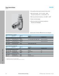
6 Anschlussbeispiele (elektrisch)<br />
Hinweis<br />
Die Leitungen für die Enable−Signale sind von der Spannungsversorgung ge<br />
trennt zu führen. Zusätzlich sind die Leitungen über entsprechende Maßnah<br />
men vor Beschädigung zu schützen.<br />
<strong>Festo</strong> MS6(N)−<strong>SV</strong> 0904a Deutsch<br />
13
MS6(N)−<strong>SV</strong><br />
Hinweis<br />
Zur einfacheren Inbetriebnahme empfiehlt es sich, einen Resetknopf (Öffner) im<br />
Spannungsversorgungskreis vorzusehen. Das Rücksetzen im Fehlerfall wird<br />
dadurch vereinfacht.<br />
MS6(N)−<strong>SV</strong> mit Multipol−Steckdose NECA−S1G9−P9−MP1<br />
Die Multipol−Steckdose NECA−−MP1 ist für statische und taktende Sicherheits<br />
ausgänge einsetzbar.<br />
<br />
Statische Enable−Signale (EN1/EN2 = 24V)<br />
Bild8<br />
Die Diagramme für das Schaltverhalten finden Sie im Kapitel 7 Inbetriebnahme"<br />
(èBild13 und Bild14).<br />
14<br />
<strong>Festo</strong> MS6(N)−<strong>SV</strong> 0904a Deutsch
MS6(N)−<strong>SV</strong><br />
<br />
Taktende Enable−Signale (EN1/EN2) zur Querschlusserkennung<br />
Die Querschlusserkennung mittels Taktsignalen wird grundsätzlich durch das<br />
verwendete Sicherheitsschaltgerät/Sicherheits−SPS durchgeführt.<br />
Bild9<br />
Hinweis<br />
Da die Taktausgänge diverser Steuerungshersteller nicht genormt sind, ist die<br />
Verwendbarkeit jeweils zu überprüfen. Liegt der Takt außerhalb der beschriebe<br />
nen Grenzen wird das vom MS6(N)−<strong>SV</strong> als Fehler erkannt und eine sichere Ab<br />
schaltung herbeigeführt.<br />
<strong>Festo</strong> MS6(N)−<strong>SV</strong> 0904a Deutsch<br />
15
MS6(N)−<strong>SV</strong><br />
MS6(N)−<strong>SV</strong> mit Multipol−Steckdose NECA−S1G9−P9−MP3<br />
<br />
<br />
Statische Enable−Signale (EN1 = 0V, EN2 = 24V)<br />
Querschlussüberwachung mit statischen Signalen möglich.<br />
Vorteil: Ein Querschluss der Leitungen EN1 und EN2 verhindert einen unbeab<br />
sichtigten Anlauf des Ventils.<br />
Bild10<br />
Die Diagramme für das Schaltverhalten finden Sie im Kapitel 7 Inbetriebnahme"<br />
(èBild15 und Bild16).<br />
16<br />
<strong>Festo</strong> MS6(N)−<strong>SV</strong> 0904a Deutsch
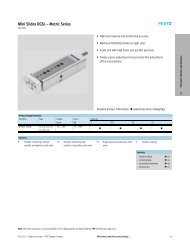
MS6(N)−<strong>SV</strong><br />
Betriebsarten Automatischer Start/Überwachter Start<br />
Betriebsarten (è Bild11):<br />
<br />
<br />
Die Betriebsart Automatischer Start" (automatic reset) ist durch eine Brücke<br />
von Klemme 5 auf 6 in der Multipolsteckdose voreingestellt (Auslieferungszu<br />
stand).<br />
Die Betriebsart Überwachter Start" (monitored reset) ist aus Sicht des<br />
Gesamtsystems als unterlagerter Start anzusehen. Führend ist immer das Frei<br />
gabesignal des Sicherheitsrelais oder der Steuerung.<br />
Hinweis<br />
Der durch den Starttaster generierte Impuls muss in einem Zeitfenster zwischen<br />
0,1s und 2s liegen.<br />
Wird der Starttaster zu lange gedrückt oder gar eingerastet, wird ein Quer<br />
schluss erkannt und das Gerät geht in den Fehlermodus.<br />
Hinweis<br />
Das Startsignal auf S34 darf erst 1s nach dem Anlegen der Enable−Signale<br />
EN1/EN2 erzeugt werden.<br />
Liegt das Startsignal vor oder zeitgleich mit den Enable−Signalen wird dieses<br />
nicht anerkannt und muss erneut gesetzt werden.<br />
<strong>Festo</strong> MS6(N)−<strong>SV</strong> 0904a Deutsch<br />
17
MS6(N)−<strong>SV</strong><br />
Automatischer Start<br />
(Auslieferungszustand)<br />
Überwachter Start<br />
Bild11<br />
18<br />
<strong>Festo</strong> MS6(N)−<strong>SV</strong> 0904a Deutsch
MS6(N)−<strong>SV</strong><br />
Meldekontakte 13/14<br />
Die Meldekontakte 13/14 sind potentialfreie Schließerkontakte eines Halbleiter<br />
relais. Über die Klemmen 3 und 4 der Multipol−Steckdose NECA kann die Meldung<br />
bei Bedarf in den Rückführkreis (feedback circuit) einer Sicherheitssteuerung auf<br />
genommen werden. Alternativ kann die Information über einen angebauten Druck<br />
sensor an die Steuerung rückgemeldet werden (nur MS6(N)−<strong>SV</strong>−−AD).<br />
Hinweis<br />
Die Belegung dieser Kontakte ist für die Erreichung der Sicherheitskategorie<br />
nicht erforderlich.<br />
Bild12<br />
Die Diagramme für das Schaltverhalten finden Sie im Kapitel 7 Inbetriebnahme"<br />
(mit Multipol−Steckdose NECA−S1G9−P9−MP1 è Bild13 und Bild14/ mit Multipol−<br />
Steckdose NECA−S1G9−P9−MP3 è Bild15 und Bild16).<br />
<strong>Festo</strong> MS6(N)−<strong>SV</strong> 0904a Deutsch<br />
19
MS6(N)−<strong>SV</strong><br />
7 Inbetriebnahme<br />
Die folgende Beschreibung der Inbetriebnahme wird grafisch unterstützt durch die<br />
Diagramme auf den nächsten Seiten (mit Multipol−Steckdose NECA−S1G9−P9−MP1<br />
è Bild13 und Bild14/ mit Multipol−Steckdose NECA−S1G9−P9−MP3 è Bild15<br />
und Bild16). Die Diagramme zeigen das Schaltverhalten der Ein− und Ausgänge im<br />
Normalbetrieb (bei eingestellter Betriebsart Automatischer Start"). Aktionen des<br />
Bedieners werden im Diagramm durch einen Pfeil symbolisiert.<br />
Für die Inbetriebnahme gehen Sie wie folgt vor:<br />
1. Betriebsdruck p1 anlegen.<br />
2. Betriebsspannung für das MS6(N)−<strong>SV</strong> einschalten.<br />
Nach 1s leuchten die beiden LEDs Power (grün) und Error (rot) für etwa 6s. In<br />
dieser Zeit testet sich das Gerät selbstständig auf Fehler. Dies ist durch ein<br />
kurzes Abblasen am Schalldämpfer erkenntlich.<br />
Anschließend erlischt die LED Error (rot). Die LED Power (grün) beginnt zu blin<br />
ken. Das MS6(N)−<strong>SV</strong> ist betriebsbereit.<br />
Solange sich das Gerät in diesem Zustand befindet, wird das Ventil durch einen<br />
Selbsttest einmal pro Stunde pneumatisch getestet.<br />
3. Enable−Signale EN1/EN2 anlegen (bei Betriebsart Überwachter Start" ist zu<br />
sätzlich ein Startsignal auf S34 erforderlich è Bild11).<br />
LED Power (grün) leuchtet. Der Ausgangsdruck p2 wird langsam aufgebaut.<br />
Die Dauer t" des Druckaufbaus wird über die am Deckel angebrachte Drossel<br />
schraube eingestellt. Entsprechend der eingestellten Drosselstellung steigt<br />
der Ausgangsdruck an (è Bild23). Bei Erreichen des Durchschaltdrucks<br />
(ca.50% vom Betriebsdruck p1) öffnet der Hauptsitz des Ventils (è Bild22).<br />
Das MS6(N)−<strong>SV</strong> ist dann betriebsbereit.<br />
Es sind keine weiteren Einstellungen erforderlich.<br />
20<br />
<strong>Festo</strong> MS6(N)−<strong>SV</strong> 0904a Deutsch
MS6(N)−<strong>SV</strong><br />
Schaltverhalten Ein− und Ausgänge im Normalbetrieb (bei eingestellter Betriebsart Auto<br />
matischer Start") für Multipol−Steckdose NECA−S1G9−P9−MP1<br />
Betriebsdruck p1<br />
Ausgangsdruck p2<br />
+L1: Betriebsspan<br />
nung<br />
EN1: Enable−Signal 1<br />
EN2: Enable−Signal 2<br />
13/14:<br />
Meldekontakte<br />
LED Power (grün)<br />
LED Error (rot)<br />
Bild13<br />
Es kommt zur Entlüftung und Ausgabe einer Fehlermeldung, wenn:<br />
S EN1 EN2 für mindestens 12ms<br />
Die Diagramme auf der nächsten Seite zeigen das genaue Schaltverhalten der Enable−Signale<br />
EN1 und EN2 mit zeitlichem Versatz. Aus der Verzögerungzeit zwischen den beiden Signalen<br />
lässt sich die maximale Reaktionszeit ableiten.<br />
<strong>Festo</strong> MS6(N)−<strong>SV</strong> 0904a Deutsch<br />
21
MS6(N)−<strong>SV</strong><br />
EN2 vor EN1 (für Multipol−Steckdose NECA−S1G9−P9−MP1)<br />
EN2:<br />
Enable−Signal 2<br />
EN1:<br />
Enable−Signal 1<br />
13/14: Melde<br />
kontakte<br />
Max. Reaktionszeit von der Entlüftung bis Belüftung: t2 + t1 = 75ms + 5ms = 80ms<br />
Max. Reaktionszeit von der Belüftung bis Entlüftung: t3 + t4 = 15ms + 2ms = 17ms<br />
EN1 vor EN2 (für Multipol−Steckdose NECA−S1G9−P9−MP1)<br />
EN2:<br />
Enable−Signal 2<br />
EN1:<br />
Enable−Signal 1<br />
13/14: Melde<br />
kontakte<br />
Max. Reaktionszeit von der Entlüftung bis Belüftung: t2 + t1 + t4 = 75ms + 5ms + 2ms = 82ms<br />
Max. Reaktionszeit von der Belüftung bis Entlüftung: t2 + t3 + t4 = 75ms + 15ms + 2ms = 92ms<br />
t1 > 5ms: Pegel von EN2/EN1 muss min. 5ms HIGH sein (Entprellzeit/Eingangsfilter/Stabili<br />
sierungszeit).<br />
t2 = 15ms: Pegel von EN2/EN1 muss min. 15ms LOW sein (Entprellzeit/Eingangsfilter/Stabili<br />
sierungszeit).<br />
t4 = 2ms: Max. interne Verzögerungszeit bedingt durch den Programmablauf.<br />
tp 1 } 2: Belüftung<br />
tp 2 } 3: Entlüftung<br />
Bild14<br />
22<br />
<strong>Festo</strong> MS6(N)−<strong>SV</strong> 0904a Deutsch
MS6(N)−<strong>SV</strong><br />
Schaltverhalten Ein− und Ausgänge im Normalbetrieb (bei eingestellter Betriebsart Auto<br />
matischer Start") für Multipolstecker NECA−S1G9−P9−MP3<br />
Betriebsdruck p1<br />
Ausgangsdruck p2<br />
+L1: Betriebsspan<br />
nung<br />
EN1: Enable−Signal 1<br />
EN2: Enable−Signal 2<br />
13/14:<br />
Meldekontakte<br />
LED Power (grün)<br />
LED Error (rot)<br />
Bild15<br />
Es kommt zur Entlüftung und Ausgabe einer Fehlermeldung, wenn:<br />
S EN1 und EN2 = 0 V (LOW)<br />
S EN1 und EN2 = 24V (HIGH)<br />
Die Diagramme auf der nächsten Seite zeigen das genaue Schaltverhalten der Enable−Signale<br />
EN1 und EN2 mit zeitlichem Versatz. Aus der Verzögerungzeit zwischen den beiden Signalen<br />
lässt sich die maximale Reaktionszeit ableiten.<br />
<strong>Festo</strong> MS6(N)−<strong>SV</strong> 0904a Deutsch<br />
23
MS6(N)−<strong>SV</strong><br />
EN2 vor EN1 (für Multipol−Steckdose NECA−S1G9−P9−MP3)<br />
EN2:<br />
Enable−Signal 2<br />
EN1:<br />
Enable−Signal 1<br />
13/14: Melde<br />
kontakte<br />
Max. Reaktionszeit von der Entlüftung bis Belüftung: t2 + t1 = 75ms + 5ms = 80ms<br />
Max. Reaktionszeit von der Belüftung bis Entlüftung: t3 + t4 = 15ms + 2ms = 17ms<br />
EN1 vor EN2 (für Multipol−Steckdose NECA−S1G9−P9−MP3)<br />
EN2:<br />
Enable−Signal 2<br />
EN1:<br />
Enable−Signal 1<br />
13/14: Melde<br />
kontakte<br />
Max. Reaktionszeit von der Entlüftung bis Belüftung: t2 + t1 + t4 = 75ms + 5ms + 2ms = 82ms<br />
Max. Reaktionszeit von der Belüftung bis Entlüftung: t2 + t3 + t4 = 75ms + 15ms + 2ms = 92ms<br />
t1 > 5ms: Pegel von EN2 (EN1) muss min. 5ms HIGH (LOW) sein (Entprellzeit/Eingangsfilter/<br />
Stabilisierungszeit).<br />
t2 = 15ms: Pegel von EN2 (EN1) muss min. 15ms LOW (HIGH) sein (Entprellzeit/Eingangsfil<br />
ter/Stabilisierungszeit).<br />
t4 = 2ms: Max. interne Verzögerungszeit bedingt durch den Programmablauf.<br />
tp 1 } 2: Belüftung<br />
tp 2 } 3: Entlüftung<br />
Bild16<br />
24<br />
<strong>Festo</strong> MS6(N)−<strong>SV</strong> 0904a Deutsch
MS6(N)−<strong>SV</strong><br />
8 Betrieb<br />
Sicherheitshinweis<br />
Im prozesssicheren (d.h. belüfteten) Zustand wird das mechanische System<br />
des MS6(N)−<strong>SV</strong> nicht getestet. Liegt die prozessbedingte Schalthäufigkeit<br />
(sicheres Entlüften) bei weniger als einmal pro Monat, muss vom Maschinenbe<br />
treiber eine Zwangsabschaltung herbeigeführt werden.<br />
Hinweis<br />
Die Pausendauer nach dem Entlüften beträgt 1s. Erst nach dieser Zeit wird ein<br />
erneutes Einschalten akzeptiert und durchgeführt.<br />
9 Wartung und Pflege<br />
S Schalten Sie zur äußeren Reinigung folgende Energiequellen ab:<br />
Betriebsspannung<br />
Druckluft.<br />
S Reinigen Sie bei Bedarf das MS6(N)−<strong>SV</strong> von außen.<br />
Zulässige Reinigungsmedien sind Seifenlauge (max. +50 °C), Waschbenzin und alle<br />
werkstoffschonenden Medien.<br />
10 Ausbau<br />
1. Schalten Sie zum Ausbau folgende Energiequellen ab:<br />
Betriebsspannung<br />
Druckluft.<br />
2. Trennen Sie die jeweiligen Anschlüsse vom MS6(N)−<strong>SV</strong>.<br />
<strong>Festo</strong> MS6(N)−<strong>SV</strong> 0904a Deutsch<br />
25
MS6(N)−<strong>SV</strong><br />
11 Außerbetriebnahme und Entsorgung<br />
Das Produkt kann in Abstimmung mit dem Entsorger komplett dem Metallrecycling<br />
zugeführt werden (z.B. EAK170402). Gegebenenfalls ist der Elektronikblock zu<br />
demontieren, der keine gefährlichen Bauteile enthält, und separat dem Elektronik<br />
schrottrecycling zuzuführen ist (EAK160216).<br />
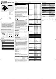
12 Zubehör<br />
Bezeichnung<br />
Multipol−Steckdose<br />
Typ<br />
NECA−S1G9−P9−MP1<br />
NECA−S1G9−P9−MP3<br />
Schalldämpfer<br />
UOS−1<br />
Bild17<br />
26<br />
<strong>Festo</strong> MS6(N)−<strong>SV</strong> 0904a Deutsch
MS6(N)−<strong>SV</strong><br />
13 Diagnose und Fehlerbehandlung<br />
LED−Anzeige<br />
Betriebszustände und Fehler werden durch Blinken der Leuchtdioden angezeigt.<br />
LED Power (grün) LED Error (rot) Diagnose<br />
aus aus Betriebsspannung fehlt<br />
leuchtet nach dem Ein<br />
schalten ca. 6 s<br />
leuchtet nach dem Ein<br />
schalten ca. 6 s<br />
MS6(N)−<strong>SV</strong> durchläuft alle Tests<br />
beim Anlauf<br />
blinkt im Sekundentakt aus MS6(N)−<strong>SV</strong> ist im Zustand Entlüften<br />
leuchtet dauerhaft aus MS6(N)−<strong>SV</strong> ist im Zustand Belüften<br />
4x kurz blinkt im Sekundentakt Fehlercode<br />
Bild18<br />
Fehlercode<br />
Die Anzeige des Fehlercodes wird durch 4−maliges kurzes Blinken der LED Power<br />
(grün) angekündigt. Anschließend gibt die LED Error (rot) den Fehlercode aus (An<br />
zahl der Blinkimpulse = Fehlercode).<br />
Die Blinkimpulse der beiden LED wiederholen sich fortlaufend. Erst wenn die Be<br />
triebsspannung zur Fehlerbehebung ausgeschaltet wird, endet das LED Blinken.<br />
Übersicht der Fehlercodes:<br />
Fehlercode<br />
Fehler<br />
6, 8 Pneumatischer Fehler oder elektrischer Installationsfehler<br />
Alle weiteren<br />
Fehlercodes<br />
Interner Fehler<br />
Bild19<br />
<strong>Festo</strong> MS6(N)−<strong>SV</strong> 0904a Deutsch<br />
27
MS6(N)−<strong>SV</strong><br />
Beispiel für Fehlercode 6<br />
Bild20<br />
1 2 1<br />
Nach 4 kurzen Blinkimpulsen der LED Power 1 folgen 6 lange Blinkimpulse der<br />
LED Error 2. Damit wird Fehlercode 6, ein pneumatischer Fehler, signalisiert. Ein<br />
pneumatischer Fehler tritt auf, wenn z.B. der Betriebsdruck unter dem erforder<br />
lichen Mindestdruck oder überhaupt nicht anliegt.<br />
Störungsbeseitigung bei auftretendem Fehlercode:<br />
Überprüfen Sie die Druckluftversorgung<br />
Überprüfen Sie die Spannungsversorgung<br />
Überprüfen Sie die Installation der Signalleitungen<br />
Nehmen Sie das Gerät in Betrieb (è Kapitel 7 Inbetriebnahme")<br />
Tauschen Sie das Gerät aus, falls der Fehler erneut auftritt<br />
28<br />
<strong>Festo</strong> MS6(N)−<strong>SV</strong> 0904a Deutsch
MS6(N)−<strong>SV</strong><br />
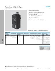
14 Technische Daten<br />
Sicherheitstechnische Kenngrößen<br />
Typ MS6−<strong>SV</strong> MS6N−<strong>SV</strong><br />
Entspricht Norm<br />
Kategorie<br />
Max. erreichbarer Performance−Level<br />
MTTF d −Wert<br />
B10 d −Wert<br />
Entspricht Norm<br />
Max. erreichbarer Safety Integrity Level<br />
PFH d −Wert<br />
Max. Einsatzdauer<br />
Sicherheitshinweis<br />
DINENISO13849−1<br />
Kategorie 3 + 4<br />
PLe"<br />
200Jahre (= hoch)<br />
500000Schaltspiele<br />
EN61508<br />
SIL3"<br />
10 −8
MS6(N)−<strong>SV</strong><br />
Typ<br />
MS6−<strong>SV</strong><br />
MS6N−<strong>SV</strong><br />
Restdruck im Normalbetrieb [bar] 0 (restdruckfrei)<br />
Max. Restdruck im Fehlerfall<br />
(worst case)<br />
[bar]<br />
0,4 (bei p1 = 10bar und voll geöffneter<br />
Drossel)<br />
Normalnenndurchfluss 1 −−> 2 [l/min] 4300 (bei p1 = 6bar, p2 = 5bar)<br />
Normaldurchfluss 2 −−> 3 [l/min] 9000 (bei p1 = 6bar)<br />
Min. Normaldurchfluss 2 −−> 3<br />
im kritischsten Fehlerfall<br />
[l/min]<br />
6000 (bei p1 = 6bar)<br />
C−Wert [l/(s*bar)] 19,3<br />
b−Wert 0,21<br />
Umgebungstemperatur<br />
Mediumstemperatur<br />
Elektrischer Anschluss<br />
Spannungsversorgung<br />
Nennwert<br />
Toleranz<br />
Max. Stromaufnahme<br />
beim Einschalten<br />
im Normalbetrieb<br />
[°C]<br />
[°C]<br />
[VDC]<br />
[VDC]<br />
[A]<br />
[A]<br />
−10 +50 (0 +50 mit Drucksensor)<br />
−10 +50 (0 +50 mit Drucksensor)<br />
Sub−D, 9−polig (das Produkt darf nur mit<br />
den zugehörigen Multipol−Steckdosen<br />
NECA−S1G9−P9−MP betrieben werden)<br />
24<br />
21,626,4<br />
1,0<br />
0,12<br />
Schutz gegen elektrischen Schlag (Schutz<br />
gegen direktes und indirektes Berühren<br />
nach EN 60204−1/IEC 204)<br />
Schaltstellungsanzeige<br />
Halbleiterrelais (Meldekontakt 13/14)<br />
Max. Spannung<br />
Max. kontinuierlicher Strom<br />
Max. Widerstand im einge<br />
schalteten Zustand<br />
Max. Leckagestrom im aus<br />
geschalteten Zustand<br />
[V]<br />
[A]<br />
[]<br />
[A]<br />
durch PELV−Netzteil<br />
LED und potenzialfreier Kontakt<br />
60<br />
0,12<br />
25 (typ. 18)<br />
1<br />
30<br />
<strong>Festo</strong> MS6(N)−<strong>SV</strong> 0904a Deutsch
MS6(N)−<strong>SV</strong><br />
Typ<br />
MS6−<strong>SV</strong><br />
MS6N−<strong>SV</strong><br />
Schaltzeit<br />
aus<br />
ein<br />
[ms]<br />
[ms]<br />
40<br />
130<br />
Min. Pausenzeit nach einer Ent<br />
lüftung<br />
[s] 1<br />
Schalldruckpegel [dB(A)] 75 mit Schalldämpfer UOS−1<br />
Schutzklasse<br />
Schutzart nach IEC60529<br />
CE−Zeichen (è Konformitätserklärung)<br />
Zulassung<br />
Brandklasse nach UL94<br />
III<br />
IP65 mit Multipol−Steckdose NECA<br />
nach EU−EMV−Richtlinie<br />
BGIA (è Konformitätserklärung)<br />
V0−V2<br />
Bild21<br />
<strong>Festo</strong> MS6(N)−<strong>SV</strong> 0904a Deutsch<br />
31
MS6(N)−<strong>SV</strong><br />
Durchschaltdruck<br />
Mit der im Deckel befindlichen Drosselschraube wird ein langsamer Druckaufbau<br />
von Ausgangsdruck p2 erzeugt. Durch Drehen der Drosselschraube kann der<br />
Druckanstieg eingestellt werden. Hat der Ausgangsdruck p2 ca. 50% vom Be<br />
triebsdruck p1 erreicht, öffnet das Ventil und am Ausgang liegt der volle Betriebs<br />
druck p1 an.<br />
100%<br />
p<br />
70%<br />
50%<br />
Toleranzbereich<br />
Durchschaltpunkt<br />
30%<br />
Befüllzeit über Drossel<br />
einstellbar<br />
t<br />
Bild22<br />
Beispiel:<br />
Ist der Betriebsdruck p1 = 4 bar, so ist unter Beachtung der zulässigen Toleranz<br />
von ±20% ein Durchschaltdruck von 1,2 bis 2,8 bar zulässig.<br />
32<br />
<strong>Festo</strong> MS6(N)−<strong>SV</strong> 0904a Deutsch
MS6(N)−<strong>SV</strong><br />
Durchfluss qn in Abhängigkeit von der Anzahl Umdrehungen n der Drossel<br />
schraube<br />
Bild23<br />
p1: 4bar<br />
p1: 6bar<br />
p1: 8bar<br />
p1: 10bar<br />
<strong>Festo</strong> MS6(N)−<strong>SV</strong> 0904a Deutsch<br />
33
MS6(N)−<strong>SV</strong><br />
Entlüftungsszeit<br />
Die nachfolgende Tabelle zeigt die Entlüftungszeit im Normalbetrieb (N) und im<br />
Fehlerfall (F) bei verschiedenen Volumina und Betriebsdrücken.<br />
Hinweis<br />
Für den Fehlerfall (F) wird der schwerstmögliche Fehler im Ventilinneren ange<br />
nommen (worst case).<br />
Normalbetrieb: N<br />
Im Fehlerfall: F<br />
Betriebsdruck<br />
3,5bar<br />
Betriebsdruck<br />
6bar<br />
Betriebsdruck<br />
10bar<br />
Entlüftungszeit [s] Entlüftungszeit [s] Entlüftungszeit [s]<br />
auf<br />
1bar<br />
auf<br />
0,5bar<br />
auf<br />
1bar<br />
auf<br />
0,5bar<br />
auf<br />
1bar<br />
auf<br />
0,5bar<br />
Volumen<br />
[l] []<br />
2 N<br />
(F)<br />
0,1<br />
(0,16)<br />
0,2<br />
(0,22)<br />
0,24<br />
(0,28)<br />
0,3<br />
(0,35)<br />
0,3<br />
(0,36)<br />
0,4<br />
(0,52)<br />
10 N<br />
(F)<br />
0,3<br />
(0,4)<br />
0,45<br />
(0,6)<br />
0,55<br />
(0,8)<br />
0,7<br />
(1,1)<br />
0,7<br />
(1,2)<br />
0,9<br />
(1,9)<br />
20 N<br />
(F)<br />
0,5<br />
(0,8)<br />
0,85<br />
(1,25)<br />
1,0<br />
(1,5)<br />
1,3<br />
(2,2)<br />
1,4<br />
(2,4)<br />
1,7<br />
(3,9)<br />
40 N<br />
(F)<br />
1,2<br />
(1,7)<br />
1,9<br />
(2,8)<br />
2,2<br />
(3,4)<br />
3,0<br />
(5,3)<br />
3,0<br />
(5,1)<br />
3,9<br />
(8,1)<br />
150 N<br />
(F)<br />
3,2<br />
(4,8)<br />
5,0<br />
(8,2)<br />
6,0<br />
(9,8)<br />
8,2<br />
(15,4)<br />
11,0<br />
(16,2)<br />
12,8<br />
(29,0)<br />
Bild24<br />
34<br />
<strong>Festo</strong> MS6(N)−<strong>SV</strong> 0904a Deutsch
MS6(N)−<strong>SV</strong><br />
Soft start/quick exhaust valve MS6(N)−<strong>SV</strong>English<br />
Contents<br />
1 Operating elements and ports . . . . . . . . . . . . . . . . . . . . . . . . . . . . . . . . . . 36<br />
2 Function and application . . . . . . . . . . . . . . . . . . . . . . . . . . . . . . . . . . . . . . . 37<br />
3 Conditions for the safe use of the product . . . . . . . . . . . . . . . . . . . . . . . . . 38<br />
4 Mechanical/pneumatic installation . . . . . . . . . . . . . . . . . . . . . . . . . . . . . . 40<br />
Mechanical . . . . . . . . . . . . . . . . . . . . . . . . . . . . . . . . . . . . . . . . . . . . . . . . . . 40<br />
Pneumatic connection 1 and 2 (thread size G½ or NPT½−14) . . . . . . . . 42<br />
Pneumatic connection 3 (thread size G1 or NPT1) . . . . . . . . . . . . . . . . . . 42<br />
5 Electrical connection . . . . . . . . . . . . . . . . . . . . . . . . . . . . . . . . . . . . . . . . . . 43<br />
6 Connection examples (electrical) . . . . . . . . . . . . . . . . . . . . . . . . . . . . . . . . 45<br />
MS6(N)−<strong>SV</strong> with NECA−S1G9−P9−MP1 multi−pin plug socket . . . . . . . . . . . 46<br />
MS6(N)−<strong>SV</strong> with NECA−S1G9−P9−MP3 multi−pin plug socket . . . . . . . . . . . 48<br />
Automatic start / Monitored start operation modes . . . . . . . . . . . . . . . . . 49<br />
Signal contacts 13/14 . . . . . . . . . . . . . . . . . . . . . . . . . . . . . . . . . . . . . . . . . . 51<br />
7 Commissioning . . . . . . . . . . . . . . . . . . . . . . . . . . . . . . . . . . . . . . . . . . . . . . . 52<br />
8 Operation . . . . . . . . . . . . . . . . . . . . . . . . . . . . . . . . . . . . . . . . . . . . . . . . . . . 57<br />
9 Care and maintenance . . . . . . . . . . . . . . . . . . . . . . . . . . . . . . . . . . . . . . . . . 57<br />
10 Dismantling . . . . . . . . . . . . . . . . . . . . . . . . . . . . . . . . . . . . . . . . . . . . . . . . . 57<br />
11 Removal from operation and disposal . . . . . . . . . . . . . . . . . . . . . . . . . . . . 58<br />
12 Accessories . . . . . . . . . . . . . . . . . . . . . . . . . . . . . . . . . . . . . . . . . . . . . . . . . . 58<br />
13 Diagnostics and error handling . . . . . . . . . . . . . . . . . . . . . . . . . . . . . . . . . 59<br />
LED display . . . . . . . . . . . . . . . . . . . . . . . . . . . . . . . . . . . . . . . . . . . . . . . . . . 59<br />
Fault code . . . . . . . . . . . . . . . . . . . . . . . . . . . . . . . . . . . . . . . . . . . . . . . . . . . 59<br />
14 Technical specifications . . . . . . . . . . . . . . . . . . . . . . . . . . . . . . . . . . . . . . . 61<br />
<strong>Festo</strong> MS6(N)−<strong>SV</strong> 0904a English<br />
35
MS6(N)−<strong>SV</strong><br />
1 Operating elements and ports<br />
MS6(N)−<strong>SV</strong> soft start/quick exhaust valve, as per DINENISO13849−1,<br />
max.achievable performance level e", category 3 + 4.<br />
1<br />
2<br />
3<br />
9<br />
4<br />
5<br />
8<br />
6<br />
7<br />
1 LED display<br />
(Power LED and Fault LED)<br />
2 Flow control screw for soft start<br />
function<br />
3 Pneumatic port 1<br />
(compressed air inlet)<br />
6 Multi−pin plug socket NECA<br />
7 Pneumatic port 3 (exhaust)<br />
8 Connection for functional earth<br />
9 Pneumatic port 2<br />
(compressed air outlet)<br />
4 Electronic insert<br />
5 Valve manifold<br />
Fig.1<br />
36<br />
<strong>Festo</strong> MS6(N)−<strong>SV</strong> 0904a English
MS6(N)−<strong>SV</strong><br />
2 Function and application<br />
The MS6(N)−<strong>SV</strong> electro−pneumatic soft start/quick exhaust valve is intended for<br />
reducing pressure quickly and safely and for building up pressure gently in<br />
pneumatic pipeline systems and terminal equipment in industry.<br />
The MS6(N)−<strong>SV</strong> is an intrinsically safe, redundant mechatronic system in<br />
accordance with the requirements set out in DINENISO13849−1.<br />
The safety−related pneumatic protective goal of the MS6(N)−<strong>SV</strong> is secure<br />
exhausting, and this is also guaranteed in the event of a fault in the valve (e.g.due<br />
to wear or contamination).<br />
The MS6(N)−<strong>SV</strong> receives secure enable signals (EN1/EN2) from commercially−<br />
available electronic or electromechanical safety switching devices via its electrical<br />
connection (NECA multi−pin plug socket Sub−D, 9−pin). These safety switching<br />
devices monitor the machine’s protective devices (e.g.EMERGENCY−STOP, light<br />
grid, electrical door switch on the protective housing, etc.).<br />
The intended use includes complying with the limit values defined in these<br />
operating instructions (e.g.operating medium, pressures, temperatures,<br />
operating voltages, flow rates).<br />
The intended use has been checked by the BGIA and is documented by a BG test<br />
certificate.<br />
Operating modes<br />
The following two operation modes are possible:<br />
Automatic start" (automatic reset)<br />
Monitored start" (monitored reset)<br />
In both operation modes, the MS6(N)−<strong>SV</strong> can be controlled using either static or<br />
dynamic enable signals (EN1/EN2) (è chapter 6 Connection examples").<br />
Note<br />
The product is suitable for industrial purposes only.<br />
<strong>Festo</strong> MS6(N)−<strong>SV</strong> 0904a English<br />
37
MS6(N)−<strong>SV</strong><br />
3 Conditions for the safe use of the product<br />
The MS6(N)−<strong>SV</strong> was developed and produced in careful compliance with the<br />
relevant norms and directives, as well as the approved technical rules. However,<br />
the device’s protective function can be impaired if the device is not used as<br />
intended. This could endanger the lives and physical condition of persons.<br />
Installation and commissioning<br />
The device must only be installed and commissioned by trained specialists.<br />
The MS6(N)−<strong>SV</strong> must only be connected and operated using the values specified in<br />
chapter 14, Technical data".<br />
Warning<br />
The use of impermissible media can damage the product.<br />
S Do not use the MS6(N)−<strong>SV</strong> together with inflammable gases or acid. The<br />
device is only intended for use with media listed as appropriate in the<br />
technical data.<br />
S<br />
Remove all transport packing such as protective wax, foils (polyamide), caps<br />
(polyethylene), cardboard boxes (except for the sealing elements of the<br />
pneumatic connections).<br />
The packing is intended for recycling (except for: oiled paper = other waste).<br />
S<br />
S<br />
Check the device for damage caused during transport. Only install undamaged<br />
devices in their original condition.<br />
Remove dirt particles in the supply lines by blowing through the tubing and<br />
hoses. In this way you will protect the MS6(N)−<strong>SV</strong> from premature failure or<br />
heavy wear (è DINISO4414, section 9.4).<br />
38<br />
<strong>Festo</strong> MS6(N)−<strong>SV</strong> 0904a English
MS6(N)−<strong>SV</strong><br />
Operation and maintenance<br />
The operator is responsible for complying with the locally−applicable safety<br />
regulations.<br />
S Check the ambient conditions on−site and the limit values for the case of<br />
application. The device must only be installed if all the values are within the<br />
permissible range (è chapter 14, Technical data")<br />
S The device must only be used in its original condition and without<br />
unauthorised modifications.<br />
Note<br />
In the event of damage caused by unauthorised manipulation or use other than<br />
that intended, the guarantee is invalidated and the manufacturer is not liable<br />
for damages.<br />
<strong>Festo</strong> MS6(N)−<strong>SV</strong> 0904a English<br />
39
MS6(N)−<strong>SV</strong><br />
4 Mechanical/pneumatic installation<br />
Mechanical<br />
Note<br />
Information about fitting module connectors, sub−bases and mounting brackets<br />
can be found in the operating instructions enclosed with the relevant<br />
accessories.<br />
S<br />
S<br />
S<br />
S<br />
S<br />
Place the MS6(N)−<strong>SV</strong> as close as<br />
possible to the location where it will<br />
be used.<br />
Place the MS6(N)−<strong>SV</strong> so that you will<br />
have sufficient space to connect the<br />
multi−pin plug socket and the<br />
silencer (èFig.2 with a UOS−1<br />
silencer from <strong>Festo</strong>).<br />
Observe the minimum permissible<br />
distance from the wall of 32mm<br />
(èFig.2).<br />
If using the MS6−WPB mounting<br />
bracket from <strong>Festo</strong>, this minimum<br />
distance is guaranteed.<br />
It can be fitted in any position.<br />
Note the direction of flow from<br />
1to2.<br />
The numbers 1 on the product<br />
housing serve as a guide (èFig.3).<br />
Fig.2<br />
1<br />
Fig.3<br />
40<br />
<strong>Festo</strong> MS6(N)−<strong>SV</strong> 0904a English
MS6(N)−<strong>SV</strong><br />
Combination with service units of the MS series<br />
Warning<br />
Incorrectly installing the device in the service unit combination can impair the<br />
MS6(N)−<strong>SV</strong>’s safety function.<br />
S Only devices that do not impede the MS6(N)−<strong>SV</strong>’s pneumatic safety measure<br />
(safe exhausting) may be placed after the MS6(N)−<strong>SV</strong>.<br />
If fitted together with one or several existing service units of the same series<br />
(èFig.4):<br />
1. Remove the MS6−END cover cap ( 1 ), if fitted, from the side to be combined<br />
(push upwards).<br />
2. Place the MS6−MV module connectors ( 2 ) in the grooves of the individual<br />
units. There must be a seal between the individual units.<br />
3. Fasten the MS6−MV module connectors with two screws.<br />
1<br />
2<br />
max 1.2Nm<br />
1 MS6−END cover cap 2 MS6−MV module connector<br />
Fig.4<br />
<strong>Festo</strong> MS6(N)−<strong>SV</strong> 0904a English<br />
41
MS6(N)−<strong>SV</strong><br />
Pneumatic connection 1 and 2 (thread size G½ or NPT½−14)<br />
If using screw connectors with width across flats larger than SW24:<br />
S Remove the MS6−END cover cap, if fitted (push upwards).<br />
If using screw connectors:<br />
S<br />
Note the maximum permitted screw−in depth of the connector threads:<br />
Max. screw−in depth [mm]<br />
ISO 228<br />
NPT<br />
10.0 10.0<br />
For larger screw−in depths, it is necessary to use MS6−AG.../AQ... sub−bases<br />
from <strong>Festo</strong>.<br />
S<br />
S<br />
Make sure that the compressed air tubing is connected correctly.<br />
Screw the connectors into the pneumatic ports using suitable sealing material.<br />
Pneumatic connection 3 (thread size G1 or NPT1)<br />
Exhausting a system using the MS6(N)−<strong>SV</strong> results in high levels of noise. We<br />
therefore recommend that you use a silencer.<br />
Warning<br />
If a commercially−available silencer is used, the body of the silencer may<br />
become clogged, which can result in reduced exhaust performance<br />
(backpressure).<br />
S Use the safety silencer designed for the device (èchapter 12 Accessories").<br />
S Only use a commercially−available silencer if it will be maintained at regular<br />
intervals by service staff and if also using a back pressure monitoring system.<br />
S<br />
S<br />
Screw the silencer into pneumatic port3. For MS6N−<strong>SV</strong>, an adapter must also<br />
be mounted between silencer and device.<br />
Make sure that there is unrestricted exhausting. Neither the silencer nor port3<br />
should be blocked.<br />
42<br />
<strong>Festo</strong> MS6(N)−<strong>SV</strong> 0904a English
MS6(N)−<strong>SV</strong><br />
5 Electrical connection<br />
Warning<br />
Electrical connections should be established only in the absence of voltage and<br />
by qualified personnel.<br />
Warning<br />
Use only power units which guarantee reliable electrical isolation of the<br />
operating voltage as per IEC/DIN EN 60204−1. Observe also the general<br />
requirements for PELV power circuits as per IEC/DIN EN 60204−1.<br />
Note<br />
Long signal cables reduce the immunity to interference.<br />
S Make sure that the signal cables are not longer than 20 m.<br />
Connect the earth cable<br />
1. Fit the earth cable ( 2 ) and the two<br />
toothed discs to the functional earth<br />
connection using the enclosed screw<br />
( 1 ) (èFig.5).<br />
There must be one toothed disc on<br />
each side of the cable lug.<br />
2. Connect the earth connection with<br />
low impedance (short cable with<br />
large cross−sectional area) to the<br />
earth potential.<br />
You can thereby avoid interference<br />
from electromagnetic sources and<br />
ensure electromagnetic compatibility<br />
in accordance with EMC directives.<br />
Fig.5<br />
2<br />
1<br />
<strong>Festo</strong> MS6(N)−<strong>SV</strong> 0904a English<br />
43
MS6(N)−<strong>SV</strong><br />
Connect multi−pin plug socket<br />
Note<br />
The MS6(N)−<strong>SV</strong> may only be used with the approved NECA−...−MP... multi−pin<br />
plug sockets (è Fig.6). For information about terminal connections, see the<br />
assembly instructions enclosed with each multi−pin plug socket.<br />
S<br />
Connect the multi−pin plug socket.<br />
Make sure that the screws are fastened tightly in order to guarantee protection<br />
class IP65. The maximum tightening torque is 0.4 ±0.1Nm.<br />
NECA−S1G9−P9−MP3<br />
Fig.6<br />
NECA−S1G9−P9−MP1<br />
44<br />
<strong>Festo</strong> MS6(N)−<strong>SV</strong> 0904a English
MS6(N)−<strong>SV</strong><br />
Inputs and outputs<br />
Terminal in<br />
multi−pin plug<br />
socket NECA<br />
I/O<br />
Assignment<br />
1 EN1 Enable signal 1<br />
(static or dynamic)<br />
2 EN2 Enable signal 2<br />
(static or dynamic)<br />
as per EN61131−2<br />
type2, max. 6mA<br />
as per EN61131−2<br />
type2, max. 6mA<br />
è examples in chapter 6,<br />
Connection examples"<br />
è examples in chapter 6,<br />
Connection examples"<br />
3 13 Signal contacts, NO potential−free<br />
Max. 120mA<br />
4 14<br />
5 A5 Contact for Automatic<br />
start" operation mode<br />
è examples in chapter 6,<br />
Connection examples"<br />
è examples in chapter 6,<br />
Connection examples"<br />
6 S34 Contact for Automatic<br />
start" or Monitored<br />
start" operation mode<br />
7 <br />
as per EN61131−2<br />
type2, max. 6mA<br />
è examples in chapter 6,<br />
Connection examples"<br />
8 +L1 Operating voltage +24VDC ±10 %<br />
9 M GND<br />
Fig.7<br />
6 Connection examples (electrical)<br />
Note<br />
The wires for the enable signals should be laid separately from the power<br />
supply. In addition, the wires should be protected against damage using<br />
suitable measures.<br />
Note<br />
For easier commissioning, we recommend planning a reset button (normally<br />
closed) in the power supply circuit. This simplifies resetting in case of fault.<br />
<strong>Festo</strong> MS6(N)−<strong>SV</strong> 0904a English<br />
45
MS6(N)−<strong>SV</strong><br />
MS6(N)−<strong>SV</strong> with NECA−S1G9−P9−MP1 multi−pin plug socket<br />
The multi−pin plug socket NECA−...−MP1 can be used for static and pulsed safety<br />
outputs.<br />
Static enable signals (EN1/EN2 = 24V)<br />
Fig.8<br />
The diagrams for the switching characteristics can be found in the chapter 7<br />
Commissioning" (èFig.13 and Fig.14).<br />
46<br />
<strong>Festo</strong> MS6(N)−<strong>SV</strong> 0904a English
MS6(N)−<strong>SV</strong><br />
<br />
Pulsed enable signals (EN1/EN2) for cross−circuit recognition<br />
Cross−circuit recognition by means of clock signals is carried out through the<br />
safety switching device/safety PLC.<br />
Fig.9<br />
Note<br />
Since the clock outputs of various controller producers are not standardised,<br />
suitability must be checked in each case. If the clock is outside the described<br />
limits, the MS6(N)−<strong>SV</strong> recognises this as a fault and performs a safe<br />
disconnection.<br />
<strong>Festo</strong> MS6(N)−<strong>SV</strong> 0904a English<br />
47
MS6(N)−<strong>SV</strong><br />
MS6(N)−<strong>SV</strong> with NECA−S1G9−P9−MP3 multi−pin plug socket<br />
<br />
<br />
Static enable signals (EN1 = 0V, EN2 = 24V)<br />
Cross circuit monitoring possible with static signals.<br />
Advantage: A cross circuit in the EN1 and EN2 wires prevents the valve from<br />
starting up unintentionally.<br />
Fig.10<br />
The diagrams for the switching characteristics can be found in the chapter 7<br />
Commissioning" (èFig.15 and Fig.16).<br />
48<br />
<strong>Festo</strong> MS6(N)−<strong>SV</strong> 0904a English
MS6(N)−<strong>SV</strong><br />
Automatic start / Monitored start operation modes<br />
Operation modes (è Fig.11):<br />
<br />
<br />
The Automatic start" (automatic reset) operation mode is preset with a<br />
current bridge from terminal 5 to terminal 6 in the multi−pin plug socket<br />
(ondelivery).<br />
The Monitored start" (monitored reset) operation mode should be seen as a<br />
subordinate start from the perspective of the entire system. The enable signal<br />
from the safety relay or the control system always has priority.<br />
Note<br />
The impulse generated by the start button has to be within a time−frame of<br />
0.1s and 2s.<br />
If the start button is held down for too long or locked down, the system<br />
identifies a cross circuit and the device is placed in fault mode.<br />
Note<br />
The start signal for S34 must not be generated until 1s after the enable signals<br />
EN1/EN2 are created.<br />
If the start signal is made before or simultaneously with the enable signals, it<br />
will not be recognised and will have to be made again.<br />
<strong>Festo</strong> MS6(N)−<strong>SV</strong> 0904a English<br />
49
MS6(N)−<strong>SV</strong><br />
Automatic start<br />
(condition upon delivery)<br />
Monitored start<br />
Fig.11<br />
50<br />
<strong>Festo</strong> MS6(N)−<strong>SV</strong> 0904a English
MS6(N)−<strong>SV</strong><br />
Signal contacts 13/14<br />
The signal contacts 13/14 are potential−free normally open contacts of a<br />
semiconductor relay. Through terminals 3 and 4 of the NECA multi−pin plug socket,<br />
the message can be picked up in the feedback circuit of a safety control system.<br />
Alternatively, the information can be reported back to the controller via an<br />
attached pressure sensor (only MS6(N)−<strong>SV</strong>−...−AD...).<br />
Note<br />
Assignment of these contacts is not required to achieve the safety category.<br />
Fig.12<br />
The diagrams for the switching characteristics can be found in the chapter 7<br />
Commissioning" (with multi−pin plug socket NECA−S1G9−P9−MP1 è Fig.13 and<br />
Fig.14 / with multi−pin plug socket NECA−S1G9−P9−MP3 è Fig.15 and Fig.16).<br />
<strong>Festo</strong> MS6(N)−<strong>SV</strong> 0904a English<br />
51
MS6(N)−<strong>SV</strong><br />
7 Commissioning<br />
The following description of commissioning is graphically supported by the<br />
diagrams on the next pages (with multi−pin plug socket NECA−S1G9−P9−MP1<br />
èFig.13 and Fig.14 / with multi−pin plug socket NECA−S1G9−P9−MP3 è Fig.15<br />
and Fig.16). The diagrams show the switching characteristics of the inputs and<br />
outputs in normal operation (if the Automatic start" operation mode has been<br />
set). The operator’s actions are marked on the diagram by an arrow.<br />
To start up the device, proceed as follows:<br />
1. Apply operating pressure p1.<br />
2. Switch on the operating voltage for the MS6(N)−<strong>SV</strong>.<br />
After 1s the two LEDs Power (green) and Error (red) light up for around 6s.<br />
During this time, the device automatically tests itself for faults. A short<br />
exhaust of air from the silencer identifies this fact.<br />
Then the LED Error (red) goes out. The Power LED (green) starts to flash.<br />
The MS6(N)−<strong>SV</strong> is ready for operation.<br />
The valve is tested pneumatically in a self−test once an hour for as long as the<br />
device remains in this state.<br />
3. Create EN1/EN2 enable signals (in Monitored start" operation mode, there<br />
also needs to be a start signal at S34 è Fig.11).<br />
Power LED (green) lights up. Output pressure p2 is built up slowly.<br />
The duration (t") of the pressure build−up is adjusted using the flow control<br />
screw attached to the cap. The output pressure rises in accordance with the<br />
flow control setting (è Fig.23). When the switch−through pressure is reached<br />
(approx.50 % of operating pressure p1), the valve’s main seat opens<br />
(èFig.22). The MS6(N)−<strong>SV</strong> is then ready for operation.<br />
No further settings are required.<br />
52<br />
<strong>Festo</strong> MS6(N)−<strong>SV</strong> 0904a English
MS6(N)−<strong>SV</strong><br />
Input and output switching characteristics in normal operation (when the Automatic start"<br />
operation mode is set) for NECA−S1G9−P9−MP1 multi−pin plug socket<br />
Operat. pressure p1<br />
Output pressure p2<br />
+L1: Operating voltage<br />
EN1: Enable signal 1<br />
EN2: Enable signal 2<br />
13/14:<br />
Signal contacts<br />
Power LED (green)<br />
Fault LED (red)<br />
Fig.13<br />
Venting and output of an error message occurs when:<br />
S EN1 EN2 for at least 12ms<br />
The diagrams on the next page show the precise switching characteristics of the Enable signals<br />
EN1 and EN2 with a time offset. The maximum reaction time can be derived from the delay<br />
between the two signals.<br />
<strong>Festo</strong> MS6(N)−<strong>SV</strong> 0904a English<br />
53
MS6(N)−<strong>SV</strong><br />
EN2 before EN1 (for NECA−S1G9−P9−MP1 multi−pin plug socket)<br />
EN2:<br />
Enable signal 2<br />
EN1:<br />
Enable signal 1<br />
13/14:<br />
Signal contacts<br />
Max. reaction time from venting until pressurisation:<br />
Max. reaction time from pressurisation until venting:<br />
t2 + t1 = 75ms + 5ms = 80ms<br />
t3 + t4 = 15ms + 2ms = 17ms<br />
EN1 before EN2 (for NECA−S1G9−P9−MP1 multi−pin plug socket)<br />
EN2:<br />
Enable signal 2<br />
EN1:<br />
Enable signal 1<br />
13/14:<br />
Signal contacts<br />
Max. reaction time from venting until pressurisation: t2 + t1 + t4 = 75ms + 5ms + 2ms = 82ms<br />
Max. reaction time from pressurisation until venting: t2 + t3 + t4 = 75ms + 15ms + 2ms = 92ms<br />
t1 > 5ms:<br />
t2 = 15ms:<br />
t4 = 2ms:<br />
tp 1 } 2:<br />
tp 2 } 3:<br />
Level of EN2/EN1 must be HIGH for min. 5ms (debounce time/input filter/<br />
stabilisation time).<br />
Max. permissible delay time between EN1 and EN2. If exceeded, the MS6(N)−<strong>SV</strong><br />
is not pressurised and an error message is output.<br />
Level of EN2/EN1 must be HIGH for min. 15ms (debounce time/input filter/<br />
stabilisation time).<br />
Max. internal delay time caused by the program sequence.<br />
Pressurisation<br />
Venting<br />
Fig.14<br />
54<br />
<strong>Festo</strong> MS6(N)−<strong>SV</strong> 0904a English
MS6(N)−<strong>SV</strong><br />
Input and output switching characteristics in normal operation (when the Automatic start"<br />
operation mode is set) for NECA−S1G9−P9−MP3 multi−pin plug<br />
Operat. pressure p1<br />
Output pressure p2<br />
+L1: Operating voltage<br />
EN1: Enable signal 1<br />
EN2: Enable signal 2<br />
13/14: Signal contacts<br />
Power LED (green)<br />
Error LED (red)<br />
Fig.15<br />
Venting and output of an error message occurs when:<br />
S EN1 and EN2 = 0 V (LOW)<br />
S EN1 and EN2 = 24V (HIGH)<br />
The diagrams on the next page show the precise switching characteristics of the Enable signals<br />
EN1 and EN2 with a time offset. The maximum reaction time can be derived from the delay<br />
between the two signals.<br />
<strong>Festo</strong> MS6(N)−<strong>SV</strong> 0904a English<br />
55
MS6(N)−<strong>SV</strong><br />
EN2 before EN1 (for NECA−S1G9−P9−MP3 multi−pin plug socket)<br />
EN2:<br />
Enable signal 2<br />
EN1:<br />
Enable signal 1<br />
13/14:<br />
Signal contacts<br />
Max. reaction time from venting until pressurisation: t2 + t1 = 75ms + 5ms = 80ms<br />
Max. reaction time from pressurisation until venting: t3 + t4 = 15ms + 2ms = 17ms<br />
EN1 before EN2 (for NECA−S1G9−P9−MP3 multi−pin plug socket)<br />
EN2:<br />
Enable signal 2<br />
EN1:<br />
Enable signal 1<br />
13/14:<br />
Signal contacts<br />
Max. reaction time from venting until pressurisation: t2 + t1 + t4 = 75ms + 5ms + 2ms = 82ms<br />
Max. reaction time from pressurisation until venting: t2 + t3 + t4 = 75ms + 15ms + 2ms = 92ms<br />
t1 > 5ms:<br />
t2 = 15ms:<br />
t4 = 2ms:<br />
tp 1 } 2:<br />
tp 2 } 3:<br />
Level of EN2 (EN1) must be HIGH (LOW) for min. 5ms (debounce time/input<br />
filter/stabilisation time).<br />
Max. permissible delay time between EN1 and EN2. If exceeded, the MS6(N)−<strong>SV</strong><br />
is not pressurised and an error message is output.<br />
Level of EN2 (EN1) must be LOW (HIGH) for min. 15ms (debounce time/input<br />
filter/stabilisation time).<br />
Max. internal delay time caused by the program sequence.<br />
Pressurisation<br />
Venting<br />
Fig.16<br />
56<br />
<strong>Festo</strong> MS6(N)−<strong>SV</strong> 0904a English
MS6(N)−<strong>SV</strong><br />
8 Operation<br />
Safety note<br />
In its process−reliable (i.e. pressurised) state, the MS6(N)−<strong>SV</strong>’s mechanical<br />
system is not tested. If the process−related switching frequency (reliable<br />
exhausting) is less than once a month, the machine’s operator has to carry out a<br />
forced switch off.<br />
Note<br />
The pause period after venting is 1s. Only after this time is a new swtich−on<br />
accepted and performed.<br />
9 Care and maintenance<br />
S Switch off the following sources of energy before cleaning the exterior of the<br />
device:<br />
Operating voltage<br />
Compressed air supply<br />
S If necessary, clean the exterior of the MS6(N)−<strong>SV</strong>.<br />
Soap suds (max. +50 °C), petroleum ether and all non−abrasive cleaning agents<br />
may be used.<br />
10 Dismantling<br />
1. Switch off the following sources of energy before dismantling:<br />
Operating voltage<br />
Compressed air supply<br />
2. Disconnect the relevant connections of the MS6(N)−<strong>SV</strong>.<br />
<strong>Festo</strong> MS6(N)−<strong>SV</strong> 0904a English<br />
57
MS6(N)−<strong>SV</strong><br />
11 Removal from operation and disposal<br />
In coordination with the waste disposal contractor, the product can completely<br />
undergo metal recycling (e.g.EAK170402). If necessary, the electronic insert,<br />
which contains no dangerous components, must be removed and sent for elec<br />
tronic scrap recycling (EAK160216).<br />
12 Accessories<br />
Designation<br />
Multi−pin plug socket<br />
Type<br />
NECA−S1G9−P9−MP1<br />
NECA−S1G9−P9−MP3<br />
Silencer<br />
UOS−1<br />
Fig.17<br />
58<br />
<strong>Festo</strong> MS6(N)−<strong>SV</strong> 0904a English
MS6(N)−<strong>SV</strong><br />
13 Diagnostics and error handling<br />
LED display<br />
Operating statuses and faults are indicated by flashing LEDs.<br />
Power LED (green) Error LED (red) Diagnosis<br />
off off Operating voltage not applied<br />
lights up for approx.<br />
6s after switching on<br />
flashes at 1 second<br />
intervals<br />
permanently<br />
illuminated<br />
lights up for approx.<br />
6s after switching on<br />
off<br />
off<br />
MS6(N)−<strong>SV</strong> runs through all tests<br />
when started up<br />
MS6(N)−<strong>SV</strong> is in the exhaust state<br />
MS6(N)−<strong>SV</strong> is in the pressurise state<br />
4 x briefly flashes at 1 second<br />
intervals<br />
Fault code<br />
Fig.18<br />
Fault code<br />
The fault code is indicated by 4 brief flashes of the Power LED (green). Then the<br />
Error LED (red) displays the fault code (number of flash pulses = fault code).<br />
The flash pulses for both LEDs repeat continuously. The LEDs only stop flashing<br />
when the operating voltage is switched off in order to eliminate the fault.<br />
Overview of the fault codes:<br />
Fault code<br />
Fault<br />
6, 8 Pneumatic fault or electrical installation fault<br />
All other fault codes<br />
Internal fault<br />
Fig.19<br />
<strong>Festo</strong> MS6(N)−<strong>SV</strong> 0904a English<br />
59
MS6(N)−<strong>SV</strong><br />
Example for fault code 6<br />
Fig.20<br />
1 2 1<br />
After four short flash pulses on the Power LED ( 1 ), there are six long flash pulses<br />
on the Error LED ( 2 ). This indicates fault code 6, a pneumatic fault. A pneumatic<br />
fault occurs if, forexample, the operating pressure is below the minimum pressure<br />
or if there is no pressure at all.<br />
Eliminating the fault when this fault code appears<br />
Check the compressed air supply<br />
Check the voltage supply<br />
Check the installation of the signal lines<br />
Put the device into operation (è chapter 7, Startup")<br />
Replace the device if the fault occurs again<br />
60<br />
<strong>Festo</strong> MS6(N)−<strong>SV</strong> 0904a English
MS6(N)−<strong>SV</strong><br />
14 Technical specifications<br />
Safety engineering index values<br />
Type MS6−<strong>SV</strong> MS6N−<strong>SV</strong><br />
Conforms to standard<br />
Category<br />
Max. achievable Performance Level<br />
MTTF d value<br />
B10 d value<br />
Conforms to standard<br />
Max. achievable Safety Integrity Level<br />
PFH d value<br />
Max. period of use<br />
Safety note<br />
DINENISO 13849−1<br />
Category 3 + 4<br />
PL e"<br />
200 years (= high)<br />
500 000switching cycles<br />
EN61508<br />
SIL 3"<br />
10 −8 < PFH d < 10 −7<br />
20 years<br />
switching frequency min. 1/month<br />
General data<br />
Type MS6−<strong>SV</strong> MS6N−<strong>SV</strong><br />
Pneumatic connection 1, 2<br />
Pneumatic connection 3<br />
Installation position<br />
G½ (ISO228)<br />
G1 (ISO228)<br />
as desired<br />
NPT½−14<br />
NPT1<br />
Operating medium<br />
Valve function<br />
Type of pilot control<br />
Pilot air supply<br />
Direction of flow<br />
Operating pressure p1<br />
Switch−through pressure<br />
[bar]<br />
[bar]<br />
filtered compressed air, lubricated or<br />
unlubricated, grade of filtration 40m<br />
3/2−way valve, single solenoid, closed<br />
direct<br />
internal<br />
non−reversible<br />
3.5 10<br />
approx. 50 % of p1 (è Fig.22)<br />
<strong>Festo</strong> MS6(N)−<strong>SV</strong> 0904a English<br />
61
MS6(N)−<strong>SV</strong><br />
Type<br />
MS6−<strong>SV</strong><br />
MS6N−<strong>SV</strong><br />
Residual pressure in normal<br />
operation<br />
Max. residual pressure in event<br />
of fault (worst case)<br />
Standard nominal<br />
flow rate 1 −−> 2<br />
[bar]<br />
[bar]<br />
[l/min]<br />
0 (no residual pressure)<br />
0.4 (if p1 = 10bar and flow control valve<br />
is fully open)<br />
4300 (if p1 = 6bar, p2 = 5bar)<br />
Standard flow rate 2 −−> 3 [l/min] 9000 (if p1 = 6bar)<br />
Min. standard flow rate 2 −−> 3<br />
inevent of critical fault<br />
[l/min]<br />
6000 (if p1 = 6bar)<br />
C value [l/(s*bar)] 19.3<br />
b value 0.21<br />
Ambient temperature<br />
Medium temperature<br />
Electrical connection<br />
Voltage supply<br />
Nominal value<br />
Tolerance<br />
Max. current consumption<br />
when switching on<br />
in normal operation<br />
[°C]<br />
[°C]<br />
[VDC]<br />
[VDC]<br />
[A]<br />
[A]<br />
−10 +50 (0 +50 with pressure sensor)<br />
−10 +50 (0 +50 with pressure sensor)<br />
Sub−D, 9−pin<br />
(the product may only be operated with<br />
the corresponding multi−pin plug<br />
sockets NECA−S1G9−P9−MP)<br />
24<br />
21.626.4<br />
1.0<br />
0.12<br />
Protection against electric shock<br />
(protection against direct and indirect<br />
contact as per EN60204−1/IEC 204)<br />
Switching position display<br />
by means of PELV power supply unit<br />
LED and floating contact<br />
62<br />
<strong>Festo</strong> MS6(N)−<strong>SV</strong> 0904a English
MS6(N)−<strong>SV</strong><br />
Type<br />
Semiconductor relay (signal contact 13/14)<br />
Max. voltage<br />
Max. continuous current<br />
Max. resistance in the<br />
switched−on state<br />
Max. leakage current in the<br />
switched−off state<br />
[V]<br />
[A]<br />
[]<br />
[A]<br />
MS6−<strong>SV</strong><br />
60<br />
0.12<br />
25 (typ. 18)<br />
1<br />
MS6N−<strong>SV</strong><br />
Response time<br />
off<br />
on<br />
[ms]<br />
[ms]<br />
40<br />
130<br />
Min. pause after venting [s] 1<br />
Noise level [dB (A)] 75 with silencer UOS−1<br />
Protection type<br />
Protection class acc. to IEC60529<br />
CE symbol (è conformity declaration)<br />
Certification<br />
Fire protection classification to UL94<br />
III<br />
IP65 with multi−pin plug socket NECA<br />
in accordance with EU EMC Directive<br />
BGIA (è conformity declaration)<br />
V0−V2<br />
Fig.21<br />
<strong>Festo</strong> MS6(N)−<strong>SV</strong> 0904a English<br />
63
MS6(N)−<strong>SV</strong><br />
Switch−through pressure<br />
The flow control screw in the cover generates a gradual pressure build−up of output<br />
pressure p2. The pressure rise can be adjusted by turning the flow control screw.<br />
Once output pressure p2 reaches approximately 50 % of operating pressurep1, the<br />
valve opens and the full operating pressure p1 is reached at the output.<br />
100 %<br />
p<br />
70 %<br />
50 %<br />
Tolerance range<br />
Switching point<br />
30 %<br />
Build−up time can be<br />
adjusted via a restrictor<br />
t<br />
Fig.22<br />
Example:<br />
If operating pressure p1 = 4 bar, a switch−through pressure of 1.2 to 2.8 bar is<br />
permissible, given the maximum permitted tolerance of ±20 %.<br />
64<br />
<strong>Festo</strong> MS6(N)−<strong>SV</strong> 0904a English
MS6(N)−<strong>SV</strong><br />
Flow rate (qn) in relation to the number of rotations (n) of the flow control screw<br />
Fig.23<br />
p1: 4 bar<br />
p1: 6 bar<br />
p1: 8 bar<br />
p1: 10 bar<br />
<strong>Festo</strong> MS6(N)−<strong>SV</strong> 0904a English<br />
65
MS6(N)−<strong>SV</strong><br />
Exhaust time<br />
The following table shows the exhaust time in normal operation (N) and in the<br />
event of a fault (F) for different volumes and operating pressures.<br />
Note<br />
The fault case (F) assumes the worst possible fault in the valve’s interior<br />
(worstcase).<br />
Normal operation: N<br />
Fault case: F<br />
Operating<br />
pressure 3.5bar<br />
Operating<br />
pressure 6bar<br />
Operating<br />
pressure 10bar<br />
Exhaust time [s] Exhaust time [s] Exhaust time [s]<br />
to 1bar<br />
to<br />
0.5bar<br />
to 1bar<br />
to<br />
0.5bar<br />
to 1bar<br />
to<br />
0.5bar<br />
Volume<br />
[l] []<br />
2 N<br />
(F)<br />
0.1<br />
(0.16)<br />
0.2<br />
(0.22)<br />
0.24<br />
(0.28)<br />
0.3<br />
(0.35)<br />
0.3<br />
(0.36)<br />
0.4<br />
(0.52)<br />
10 N<br />
(F)<br />
0.3<br />
(0.4)<br />
0.45<br />
(0.6)<br />
0.55<br />
(0.8)<br />
0.7<br />
(1.1)<br />
0.7<br />
(1.2)<br />
0.9<br />
(1.9)<br />
20 N<br />
(F)<br />
0.5<br />
(0.8)<br />
0.85<br />
(1.25)<br />
1.0<br />
(1.5)<br />
1.3<br />
(2.2)<br />
1.4<br />
(2.4)<br />
1.7<br />
(3.9)<br />
40 N<br />
(F)<br />
1.2<br />
(1.7)<br />
1.9<br />
(2.8)<br />
2.2<br />
(3.4)<br />
3.0<br />
(5.3)<br />
3.0<br />
(5.1)<br />
3.9<br />
(8.1)<br />
150 N<br />
(F)<br />
3.2<br />
(4.8)<br />
5.0<br />
(8.2)<br />
6.0<br />
(9.8)<br />
8.2<br />
(15.4)<br />
11.0<br />
(16.2)<br />
12.8<br />
(29.0)<br />
Fig.24<br />
66<br />
<strong>Festo</strong> MS6(N)−<strong>SV</strong> 0904a English
MS6(N)−<strong>SV</strong><br />
<strong>Festo</strong> MS6(N)−<strong>SV</strong> 0904a<br />
67
MS6(N)−<strong>SV</strong><br />
Weitergabe sowie Vervielfältigung dieses Dokuments,<br />
Verwertung und Mitteilung seines Inhalts sind verboten,<br />
soweit nicht ausdrücklich gestattet. Zuwiderhandlungen<br />
verpflichten zu Schadenersatz. Alle Rechte sind für den<br />
Fall der Patent−, Gebrauchsmuster oder Geschmacks−<br />
mustereintragung vorbehalten.<br />
The reproduction, distribution and utilization of this<br />
document as well as the comunication of its contents to<br />
others without express authorization is prohibited.<br />
Offenders will be held liable for the payment of damages.<br />
All rights reserved in the event of the grant of a patent,<br />
utility module or design.<br />
Copyright:<br />
E<strong>Festo</strong> AG&Co. KG,<br />
Postfach<br />
D−73726 Esslingen<br />
Phone:<br />
+49/711/347−0<br />
Fax:<br />
+49/711/347−2144<br />
e−mail:<br />
service_international@festo.com<br />
Internet:<br />
http://www.festo.com<br />
Original: de<br />
Version: 0904a<br />
68<br />
<strong>Festo</strong> MS6(N)−<strong>SV</strong> 0904a