PDF - NASA
PDF - NASA
PDF - NASA

You also want an ePaper? Increase the reach of your titles
YUMPU automatically turns print PDFs into web optimized ePapers that Google loves.
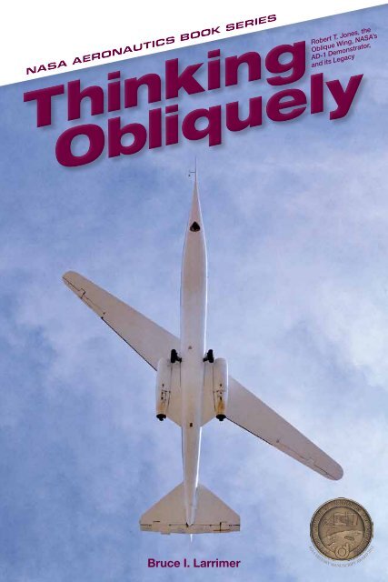
<strong>NASA</strong> AERONAUTICS BOOK SERIES<br />
AIAA HISTORY MANUSCRIPT AWARD 2013<br />
Bruce I. Larrimer
.<br />
Bruce I. Larrimer
Library of Congress Cataloging-in-Publication Data<br />
Larrimer, Bruce I.<br />
Thinking obliquely : Robert T. Jones, the Oblique Wing, <strong>NASA</strong>'s AD-1<br />
Demonstrator, and its legacy / Bruce I. Larrimer.<br />
pages cm<br />
Includes bibliographical references.<br />
1. Oblique wing airplanes--Research--United States--History--20th<br />
century. 2. Research aircraft--United States--History--20th century.<br />
3. United States. National Aeronautics and Space Administration--<br />
History--20th century. 4. Jones, Robert T. (Robert Thomas), 1910-<br />
1999. I. Title.<br />
TL673.O23L37 2013<br />
629.134'32--dc23<br />
2013004084<br />
Copyright © 2013 by the National Aeronautics and Space Administration.<br />
The opinions expressed in this volume are those of the authors and do not<br />
necessarily reflect the official positions of the United States Government or<br />
of the National Aeronautics and Space Administration.<br />
This publication is available as a free download at<br />
http://www.nasa.gov/ebooks.
Introduction<br />
v<br />
Chapter 1: American Genius: R.T. Jones’s Path to the Oblique Wing ..............1<br />
Chapter 2: Evolving the Oblique Wing ............................................................ 41<br />
Chapter 3: Design and Fabrication of the AD-1 Research Aircraft ................75<br />
Chapter 4: Flight Testing and Evaluation of the AD-1 ................................... 101<br />
Chapter 5: Beyond the AD-1: The F-8 Oblique Wing Research Aircraft ....... 143<br />
Chapter 6: Subsequent Oblique-Wing Plans and Proposals ....................... 183<br />
Appendices<br />
Appendix 1: Physical Characteristics of the Ames-Dryden AD-1 OWRA 215<br />
Appendix 2: Detailed Description of the Ames-Dryden AD-1 OWRA 217<br />
Appendix 3: Flight Log Summary for the Ames-Dryden AD-1 OWRA 221<br />
Acknowledgments 230<br />
Selected Bibliography 231<br />
About the Author 247<br />
Index 249<br />
iii
This time-lapse photograph shows three of the various sweep positions that the AD-1's unique<br />
oblique wing could assume. (<strong>NASA</strong>)<br />
iv
On December 21, 1979, the National Aeronautics and Space Administration<br />
(<strong>NASA</strong>) AD-1 Oblique Wing Research Aircraft (OWRA) took off from<br />
the main runway at Edwards Air Force Base (AFB), CA, for a 45-minute<br />
checkout flight. It marked the world’s first flight of a piloted oblique-wing<br />
airplane. This historic flight, which was flown with the airplane’s wing<br />
at its “straight” (0-degree angle) position, was soon followed by flights at<br />
wing angles of 15 degrees, 20 degrees, 45 degrees, and finally on April 24,<br />
1981, at the 60-degree-angle design goal, thus proving the aerodynamic<br />
concept of an airplane with an oblique-wing configuration. This initial<br />
oblique-wing program, which ran from 1976 through 1982, was a joint<br />
effort between <strong>NASA</strong>’s Ames Research Center and Dryden Flight Research<br />
Center, CA, thus giving rise to the aircraft’s name—Ames-Dryden AD-1<br />
Oblique Wing Research Aircraft. 1 Extensive research, wind tunnel and<br />
computer-code testing, and model-building and testing projects were<br />
undertaken at Ames, and flight simulation, flight testing, and flight evaluation<br />
were conducted at Dryden. While the concept of the oblique wing<br />
was developed during World War II, and the landmark wind tunnel tests<br />
of John P. Campbell and Hubert M. Drake were undertaken just following<br />
the end of the war, most aeronautical attention in the postwar era<br />
concentrated on the continuous refinement of symmetrical point-forward<br />
swept-wing aircraft.<br />
Serious attention, however, once again turned to the oblique wing<br />
in the 1970s, resulting in the research activities discussed in this book.<br />
Chapter 1 reviews the life of <strong>NASA</strong> aerodynamicist Robert T. Jones and<br />
his path to the oblique wing. Chapter 2 covers the extensive wind tunnel,<br />
model, computer-code, and simulation testing, first at Langley and later at<br />
Ames, as well as a number of <strong>NASA</strong> industry design contracts undertaken<br />
by Boeing and Lockheed. Chapter 3 reviews the design and fabrication of<br />
the AD-1 Oblique Wing Research Aircraft and its subsequent proposed<br />
use as a joined-wing demonstrator. Chapter 4 describes the flight testing<br />
and flight evaluation of the AD-1. Chapter 5 reviews the supersonic<br />
F-8 followup oblique-wing program. And, finally, chapter 6 reviews the<br />
subsequent oblique-wing plans and proposals. Appendices present the<br />
physical characteristics of the AD-1 aircraft, a detailed description of it,<br />
and a summary flight log of its flight research program.<br />
v
Thinking Obliquely<br />
Writing the history of the AD-1 proved both a challenge and a pleasure. I<br />
am very grateful to all who have assisted me in this endeavor. A listing of those<br />
who were particularly helpful follows the appendices.<br />
Bruce I. Larrimer<br />
Columbus, OH<br />
March 12, 2012<br />
1. From September 27, 1959, until March 26, 1976, <strong>NASA</strong> Dryden was known as the <strong>NASA</strong> Flight<br />
Research Center. From March 26, 1976, until October 1, 1981, the Center was known as the<br />
<strong>NASA</strong> Hugh L. Dryden Flight Research Center. From October 1, 1981, until March 1, 1994, the<br />
Center was part of <strong>NASA</strong> Ames and was known as the <strong>NASA</strong> Ames-Dryden Flight Research<br />
Facility. On March 1, 1994, the Center once again became a separate operational entity and<br />
since then has used its previous designation as the <strong>NASA</strong> Hugh L. Dryden Flight Research<br />
Center, being more simply known as the <strong>NASA</strong> Dryden Flight Research Center, which is how it is<br />
referred to throughout this book.<br />
vi
NACA-<strong>NASA</strong> research scientist Robert T. Jones. (<strong>NASA</strong>)<br />
viii
CHAPTER 1<br />
American Genius<br />
R.T. Jones’s Path to the Oblique Wing<br />
Robert Thomas “R.T.” Jones was born on May 28, 1910, in the farming community<br />
of Macon, MO, and died on August 11, 1999, in Los Altos Hills, CA.<br />
In the intervening 89 years, Jones more than fulfilled the definition of genius,<br />
and his lifetime in aeronautics constituted a particularly productive and welllived<br />
life. In his progression to distinction, Jones resembles far more the 17th<br />
century’s largely self-taught and broadly interested “natural philosopher” than<br />
the rigorously educated, university-trained STEM (science, technology, engineering,<br />
and mathematics) über-specialized professional of the modern era. 1<br />
Jones’s lifelong consuming interest in aviation started at an early age when<br />
he built rubberband-powered model airplanes and assembled airplane models<br />
with scaled drawings from the Ideal Model Airplane Supply Company. In his<br />
rural Macon, MO, high school, Jones acquired an interest in mathematics<br />
from his math teacher, Iva Z. Butler, who guided him “along the intricate<br />
path through exponents, logarithms, and trigonometry.” 2 Following the<br />
nationwide increase in interest in aviation resulting from Charles Lindbergh’s<br />
nonstop transatlantic flight in 1927, Jones was readily able to purchase the<br />
magazines Aviation and Aero Digest in his hometown of Macon. These publications<br />
contained technical articles, which Jones read with great interest,<br />
as well as notices of Technical Reports (TRs) of the National Advisory<br />
Committee for Aeronautics (NACA, the forerunner to <strong>NASA</strong>), which Jones<br />
was able to purchase from the Government Printing Office for as little as<br />
10 or 15 cents. In regard to his interest in aviation, Jones noted that he<br />
must have puzzled his high school English teacher with all the essays he<br />
wrote on aeronautics-related subjects. After graduation, Jones attended the<br />
University of Missouri to study engineering but left college after the first year<br />
because the university did not offer courses in aeronautics and he “found the<br />
other subjects rather uninteresting.” 3 In dropping out of college after a year,<br />
Jones followed in the footsteps of his father, who also had quit after 1 year,<br />
and then read the law and passed the bar examination to practice as an<br />
attorney in Missouri.<br />
1
Thinking Obliquely<br />
The Evolution of a Practical Engineer-Scientist<br />
After leaving college, Jones returned to Macon, working for the Marie Meyer<br />
Flying Circus. In exchange for odd jobs, such as fueling its Curtiss JN-4 Jenny<br />
aircraft and patching its often-damaged fabric-covered lower wingtips, Jones<br />
received free flying lessons—although it would take another 50 years before<br />
he would make his first solo flight and subsequently receive his pilot’s license.<br />
In 1929, at the age of 19, Jones was hired as the chief and only engineer of<br />
the Nicholas-Beazley Airplane Company, Inc., of Marshall, MO, after Charles<br />
Fower, a friend of Jones’s, told Russell Nicholas that Jones “knew everything<br />
there was to know about airplanes.” Jones obtained this engineering position due<br />
to the departure of Walter Barling, who had been the principal designer of the<br />
company’s NB-3 of 1928, a low-wing, single-engine, two-place, open-cockpit<br />
monoplane of straightforward design that enjoyed brief, modest commercial<br />
success. Later, the company hired Thomas Kirkup, a certified engineer from<br />
England who taught Jones how to undertake stress calculations. At its peak<br />
production, Nicholas-Beazley, which Jones noted was well-placed to become<br />
the center of small airplane production in the United States, was producing an<br />
airplane per day, but the company failed during the Great Depression and Jones<br />
soon found himself back in his hometown of Macon. During this time back in<br />
Macon, Jones continued his self-study by reading books on aeronautics, including<br />
Max M. Munk’s Fundamentals of Fluid Mechanics for Aircraft Designers, his<br />
introduction to an individual who was himself a towering figure in aeronautics<br />
and who would have a profound effect upon Jones’s life and work. 4<br />
During the depth of the Depression, Jones, desperate for work, hitched<br />
a ride to Washington, DC, with some neighbors. Once in Washington, he<br />
immediately visited his local Congressman, who secured for him a position<br />
as an elevator operator in the House Office Building. Jones took advantage of<br />
this welcome security to further his study of mathematics by studying books<br />
from the Library of Congress and attending evening classes in aerodynamics<br />
taught by Max Munk at Catholic University. A decade previously, Munk<br />
had introduced modern scientific airfoil development to America. Munk was<br />
born in Hamburg, Germany, in 1880. He studied under Dr. Ludwig Prandtl,<br />
was a contemporary of Theodore von Kármán, received two doctoral degrees<br />
from the Göttingen University, and moved to the United States in 1920 to<br />
join the National Advisory Committee for Aeronautics’s Langley Memorial<br />
Aeronautical Laboratory (now <strong>NASA</strong> Langley Research Center). After a productive<br />
if tempestuous time with the NACA, Munk left the agency to take up<br />
a teaching position at Washington’s Catholic University and to serve as technical<br />
editor of the magazine Aero Digest. 5 Soon after arriving in Washington,<br />
Jones paid a visit to Munk and informed the professor that he had read his<br />
2
American Genius<br />
book on fluid dynamics for aircraft designers. Listening to Jones, Munk, a brilliant<br />
if irritable personality, was impressed to the point of promptly inviting<br />
his young visitor to take his course in aerodynamics. When Jones modestly<br />
demurred, stating that he lacked an undergraduate degree, Munk challenged<br />
him to define a derivative of a function. When Jones promptly did so, Munk<br />
equally promptly admitted him to the course.<br />
Jones realized that in order to become a successful engineer, he would need<br />
to know more about mathematics. Fortunately, his status as a congressional<br />
employee, coupled with the close proximity of the House Office Building to the<br />
Library of Congress, readily enabled Jones to obtain works on various branches<br />
of mathematics. He read Hermann Grassmann’s Die Ausdehnungslehre, one of<br />
the most influential texts in the history of mathematics, written by an individual<br />
who was, in his broad range of interests and largely self-taught abilities, very<br />
much like Jones himself, though, sadly, unrecognized for his contributions in<br />
his lifetime. 6 In particular, Jones became fascinated with the “time plus space”<br />
theory of quaternions (four-element multiples of real numbers consisting of<br />
a scalar [time] element and three vector [space] elements), first derived by the<br />
Anglo-Irish mathematician Sir William Hamilton, which contributed much of<br />
the underpinning of quantum theory. 7 Jones credited the scholarship of both<br />
men with helping him during his years with the NACA.<br />
In addition, while at the Library of Congress, Jones made the acquaintance<br />
of Dr. Albert F. Zahm, a physicist and influential aerodynamics researcher<br />
who had established America’s first wind tunnel–equipped research laboratory<br />
at Catholic University in 1901 and, later on, helped found another at<br />
the Washington Navy Yard. By the time he met Jones, Zahm was managing<br />
the Library’s aeronautics collections, though he still undertook some research<br />
and maintained a determinedly future-focused mindset. One of the topics<br />
he pursued was the challenge of upper-atmospheric near-space flight, and<br />
he invited Jones to assist him. 8 Impressed, he subsequently furnished Jones<br />
a contact who was to help the young Midwesterner obtain his job with the<br />
NACA—Congressman David J. Lewis. Lewis took to Jones for, like the young<br />
man, he had achieved his own success without formal education, and he was<br />
likewise fascinated with mathematics. Subsequently, Jones tutored Lewis in<br />
mathematics, impressing the Congressman with his extraordinary knowledge.<br />
Having impressed Munk, Zahm, and Lewis, Jones had no difficulty securing<br />
their recommendations to obtain, in 1934, a temporary 9-month appointment<br />
as a Junior Scientific Aide at the NACA’s Langley Aeronautical Laboratory<br />
under a Roosevelt-era employment program.<br />
The temporary appointment lasted until Jones’s supervisors were able to<br />
make it permanent. At Langley, Jones first worked under Fred E. Weick, a wellknown<br />
engineer who in the 1930s continued earlier work on inherent stability<br />
3
Thinking Obliquely<br />
undertaken by Jerome C. Hunsaker and E.B. Wilson. Weick was also interested<br />
in designing an airplane with a simplified “two-control” (independent pitch<br />
control but interlinked roll and yaw control) pilot operation, and Jones was<br />
given the task of making the dynamic calculations. Jones’s calculations indicated<br />
that Weick’s two-control operation, subsequently employed on Weick’s<br />
two-control Erco Ercoupe that Jones enjoyed flying in later years, would be<br />
better achieved by placing primacy upon the ailerons instead of the rudder<br />
as the principal control device driving directional changes. Weick, according<br />
to Jones, also realized that a two-control system would need dynamically<br />
stable landing gear, driving his development of a tricycle gear with fixed wheels<br />
behind the center of gravity and a steerable nose wheel ahead.<br />
While Weick was not the first to develop such a configuration—for example,<br />
it had appeared before the First World War in the pusher designs of Glenn<br />
Curtiss—the Ercoupe certainly encouraged its use and almost universal subsequent<br />
adaptation. As for Jones, his work on two-control flight control systems<br />
later influenced his wartime work on guided weapons. 9<br />
Once Jones’s 9-month appointment expired, the Langley staff found a way<br />
to retain Jones by skipping him a grade above junior engineer, which required<br />
a college degree, to the next higher professional engineering position, which<br />
already assumed that the candidate had a college degree and thus failed to list<br />
a degree as a position requirement. This led to Jones’s long career with the<br />
NACA and <strong>NASA</strong>.<br />
William R. Sears, himself a noted aeronautical engineer, noted of Jones<br />
that during his long civil service career, Jones had become “one of the world’s<br />
leading aerodynamicists, [who] made discoveries that have changed the history<br />
of aeronautics, and received important honors.” 10 In 1947, the Institute of the<br />
Aeronautical Sciences (one of two professional societies—the other being the<br />
American Rocket Society—that merged to form the American Institute of<br />
Aeronautics and Astronautics [AIAA]) awarded Jones its 1946 Sylvanus Albert<br />
Reed Award “For his contributions to the understanding of flow phenomena<br />
around wings and bodies at speeds below and above the speed of sound.” 11 In<br />
1971, Jones was awarded an honorary doctorate degree by the University of<br />
Colorado for his contributions to aeronautics, and in 1973, he was elected to<br />
the National Academy of Engineering. Jones received the Prandtl Ring award<br />
from the German Aeronautical Society in 1978. In 1981, the Smithsonian<br />
Institution selected Jones to receive its prestigious Langley Medal (named for<br />
Smithsonian Institution Secretary and pioneer astrophysicist Samuel Pierpont<br />
Langley, himself a notable pioneer of flight), which is awarded for “especially<br />
meritorious investigation in the field of aerospace science.” 12 The Langley<br />
Medal was awarded to Jones in recognition of his “extensive contributions in<br />
theoretical aerodynamics, particularly with regard to development of the swept<br />
4
American Genius<br />
The first production Ercoupe, at its College Park, MD, plant, 1939. (NASM)<br />
wing, supersonic area rule and, more recently, the oblique wing.” 13 In 1981,<br />
Jones received the President’s Award for Distinguished Civilian Service, which<br />
read in part as follows: “Of major consequences are his triangular wing concept,<br />
the independence principle for the three-dimensional boundary layers, and the<br />
concept of the oblique wing boom-free supersonic airplane.” 14<br />
Jones’s Other Interests<br />
In addition to aeronautics, R.T. Jones had a wide range of other areas of interest<br />
and expertise, again reflecting, to an almost uncanny degree, Hermann<br />
Grassmann and Sir William Hamilton, whose work had furnished so much<br />
insight for his own work. Jones’s polymath tendencies are evident in at least<br />
nine reports prepared while at the <strong>NASA</strong> Ames Research Center and at least<br />
four reports prepared at the Avco-Everett Research Laboratory, MA, during<br />
his approximately 7 years of voluntary absence from <strong>NASA</strong>. At <strong>NASA</strong> Ames,<br />
these reports covered such varied topics as:<br />
•<br />
•<br />
•<br />
•<br />
•<br />
•<br />
modified Gregorian and Cassegrainian mirror systems,<br />
time calculations for interplanetary travel,<br />
work on lenses and telescopes of an unusual optical design,<br />
extending the Lorentz Transformation by characteristics coordinates,<br />
a review of some selected space-science problems<br />
and accomplishments,<br />
analysis of accelerated motion in the theory of relativity,<br />
5
Thinking Obliquely<br />
• conformal coordinates associated with uniformly accelerated<br />
motion, and<br />
• conformal coordinates associated with space-like motions.<br />
His studies at Avco-Everett Research Laboratories included the following<br />
topics:<br />
•<br />
•<br />
•<br />
•<br />
wide-angle lenses with aspheric correcting surfaces,<br />
motions of a liquid in a pulsating bulb with application to problems<br />
of blood flow,<br />
a theory of synchronous arterio-arterial blood pumps, and<br />
studies of blood flow (as a followup, he undertook a study of fluid<br />
dynamics of heart assist devices).<br />
Even in leisure and family pursuits, Jones could not resist the opportunity<br />
to study and learn new things—and then to improve upon them. When his<br />
daughter developed an interest in violins, Jones even built a number of violins,<br />
making a detailed acoustical study of each. In testing two of the violins,<br />
Jones concluded that “It will be noted that the second violin has accentuated<br />
overtones in the 2000 to 3000 Hz [hertz] range, the main body resonance is at<br />
450 Hz, and the air resonance peak is somewhat lower in amplitude,” adding<br />
(with just a touch of obvious pride), “This violin is preferred by musicians who<br />
have tried both.” 15<br />
Jones, however, never left his lifelong interest in aeronautics. He returned to<br />
<strong>NASA</strong> Ames in 1970 and worked there until his retirement in 1981. During<br />
this time period, Jones concentrated mostly on his oblique-wing concept and<br />
its potential development as a high-speed transport. After retiring from <strong>NASA</strong>,<br />
Jones joined the faculty of Stanford University, where he served until 1997 as a<br />
consulting professor in the Department of Aeronautics and Astronautics while,<br />
at the same time, maintaining an informal relationship with <strong>NASA</strong> Ames.<br />
While at Stanford, Jones’s work on the oblique-wing concept moved toward<br />
developing a pure oblique flying wing, an idea he had long nurtured. After<br />
Jones’s death in 1999, Walter G. Vincenti, a veteran NACA-<strong>NASA</strong> engineer<br />
and distinguished historian of technology, noted in his Biographical Memoir of<br />
Robert T. Jones (written for the prestigious National Academy of Sciences) that<br />
[t]hose who worked with R. T. marveled at how he arrived at his<br />
ideas, seemingly intuitively and frequently in terms of physical<br />
models and analogies. He could use highly sophisticated mathematics<br />
deductively when necessary, but he did so mostly to<br />
support his ideas and explore their consequences. In the initial<br />
report on his concept of sweepback he began conventionally with<br />
a mathematical derivation followed by three physical arguments<br />
and explanations. Events at the time suggest that the mathematics<br />
6
American Genius<br />
Robert T. Jones at home, making a violin. Note the oblique-wing radio-controlled model airplane<br />
and a reflector telescope, also made by Jones, July 30, 1982. (Photograph © Roger Ressmeyer/<br />
Corbis Images)<br />
actually came to R. T.’s mind after the physical concepts and had<br />
been put into the report in response to editorial-committee objections.<br />
Whatever the situation, the fact is that things that seemed<br />
clear and obvious to him in his physical explanations often caused<br />
the rest of us difficulty and struggle to master. 16<br />
Jones’s Early Work at Langley Aeronautical Laboratory<br />
Jones established his reputation between 1936 and 1946, when he worked on<br />
a number of different engineering assignments and wrote entirely or coauthored<br />
at least 21 NACA reports, notes, and studies covering a wide range of<br />
topics. Taken together, they constitute a prodigious output and extraordinary<br />
technical and scientific accomplishment. If he had done nothing else, this<br />
work, culminating in his enunciation of the thin, high-speed slender delta<br />
7
Thinking Obliquely<br />
wing and the swept wing, would have on its own sufficed to secure his place<br />
in aviation history.<br />
Viewed sequentially to the point just prior to his commencing research on<br />
swept planforms, his corpus of accomplishment included:<br />
• Report No. 560 (1936), reviewing a simplified treatment of the<br />
application of mathematician and physicist Oliver Heaviside’s operational<br />
methods to problems of airplane dynamics.<br />
• Report No. 570 (1936, coauthored with Fred E. Weick), analyzing<br />
the lateral controllability of an airplane in which both the static rolling<br />
and yawing moments supplied by the controls and the reactions<br />
due to the inherent stability of the airplane were taken into account.<br />
• Report No. 579 (1936), examining the two-control operation of<br />
an airplane.<br />
• Technical Note (TN) No. 586 (1936, with Albert I. Nerken), studying<br />
the reduction of aileron operating force by differential linkage;<br />
• Report No. 605 (1937, a Fred E. Weick report to which Jones<br />
contributed), examining a resume and analysis of NACA<br />
lateral-control research.<br />
• Report No. 635 (1938, coauthored with Henry A. Pearson)—examining<br />
the theoretical stability and control characteristics of wings<br />
with various amounts of taper and twist.<br />
• Report No. 638 (1938), studying the influence of lateral stability<br />
of disturbed motions of an airplane with special reference to the<br />
motions produced by wind gusts.<br />
• Technical Note No. 667 (1938), addressing the operational treatment<br />
of the nonuniform lift theory in airplane dynamics.<br />
• Report No. 681 (1940), studying the unsteady lift of a wing having<br />
finite aspect ratio.<br />
• Technical Note No. 771 (1940, coauthored with Leo F. Fehlner),<br />
reviewing the transient effects of the wing’s turbulent wake on the<br />
horizontal tail of an airplane.<br />
• Report No. 709 (1941, coauthored with Doris Cohen), analyzing<br />
the stability of an airplane with free controls.<br />
• Report No. 722 (1941, coauthored with Doris Cohen)—studying a<br />
graphical method of determining pressure distribution in two-dimensional<br />
flow.<br />
• An article (1941), examining the theoretical correction for the lift of<br />
wings having an elliptical planform.<br />
• Technical Report No. 837 (1941), addressing problems involved in<br />
the stability and control of tailless airplanes.<br />
8
American Genius<br />
• Wartime Report L-464 (1942, coauthored with Milton B. Ames, Jr.),<br />
covering wind tunnel testing of beveled trailing edges to reduce the<br />
hinge moment of a control surface.<br />
• Report No. 731, (1941, coauthored with Doris Cohen), examining<br />
a theoretical analysis to determine the optimum planforms for<br />
control surfaces.<br />
• Wartime Report L-233 (1943, coauthored with Joseph W. Wetmore),<br />
dealing with emergency measures for increasing the range of<br />
fighter airplanes.<br />
• Report No. 798 (1943, coauthored with Harry Greenberg), covering<br />
the effect of hinge-moment parameters on elevator stick forces in<br />
rapid maneuvers.<br />
• Wartime Report L-651 (1943, coauthored with W.J. Underwood),<br />
involving a wind tunnel investigation of a beveled aileron shape<br />
designed to increase the useful deflection range.<br />
• Report No. 801 (1943), presenting a method for studying the hunting<br />
oscillations of an airplane with a simple type of automatic flight<br />
control system. 17<br />
Jones’s NACA activities during this time period included important work<br />
in the emerging field of guided weapons research, and it was this work that<br />
led him, eventually, to conceptualize the American delta and swept wing. In<br />
1944, he was assigned to work at Eglin Field to help the U.S. Army Air Corps<br />
develop guided missiles, including a glide bomb designed to be launched from a<br />
B-17. The glider was equipped with a heat seeker developed by Franklin Offner<br />
and an autopilot made by Laurens Hammond, designer and manufacturer of<br />
electric organs. The initial tests, however, were not very successful because the<br />
bomb was guided to its target by rudders, which imparted directional control<br />
(yaw control, i.e., left-right control) but still did not ensure sufficient accuracy.<br />
Drawing upon his earlier experience with two-control flight control systems<br />
with Weick at Langley, Jones recommended using aileron (roll) control, which<br />
greatly enhanced delivery accuracy.<br />
In 1944, Jones was detailed to join a U.S. Army Air Force’s Air Technical<br />
Service Command (ATSC, forerunner of the modern U.S. Air Force [USAF]<br />
Materiel Command) team sent to Eglin Field (now Eglin Air Force Base) in<br />
Florida to test the pulsejet-powered Republic JB-2 Loon guided missile. An<br />
American copy of the Fieseler FZG-76 (better known to history as the infamous<br />
Nazi V-1 Buzz bomb—the V standing for Vergeltungswaffe, or “Revenge<br />
Weapon,” its Nazi propaganda designation—that savaged London in 1944<br />
through early 1945), the JB-2 was America’s first jet-age cruise missile.<br />
Unlike the preset V-1 (which could deviate as much as 8 miles over approximately<br />
120 miles), the JB-2 used ground radar tracking and radio-controlled<br />
9
Thinking Obliquely<br />
Republic JB-2 ready for flight. (USAF)<br />
guidance to reduce its course deviation to just one-quarter mile at a range of<br />
100 miles—extremely accurate by the standards of the day. 18 While the V-1<br />
employed a launching sled and steam catapult (with the steam produced by the<br />
reaction of concentrated hydrogen peroxide poured over potassium permanganate),<br />
the JB-2 was boosted to flight speed by solid-fuel rockets, considered<br />
both safer and less complex for the launching team. It seemed a simple matter<br />
to modify the missile for rocket boost: simply by aligning the thrust vector of<br />
the rockets through the missile’s center of gravity, the test team could launch<br />
the JB-2 into the air.<br />
But at the time, the JB-2 was in trouble. It took many attempts before the<br />
team determined the proper configuration, to prevent the powerful rockets<br />
from tearing the missile apart during launch. Initially, only 20 percent of all<br />
missiles launched successfully. Thanks in large measure to Jones and a more<br />
analytical approach to the missile’s launch dynamics, by war’s end, the figure<br />
had increased to 80 percent. 19 Jones also used gyros from the JB-2 to devise a<br />
bilaterally symmetric flight control system to improve the one developed by<br />
Hammond for the Northrop Company’s rival JB-10 flying wing “flying bomb.”<br />
In regard to this wartime service, an Army Air Forces Air Technical Service<br />
Command letter commending Jones for his service stated:<br />
It will be noted that the Air Technical Service Command desires to<br />
commend Mr. Robert T. Jones of the Langley Memorial Aeronautical<br />
Laboratory for his assistance in the successful initiation of this project.<br />
This office also wishes to take this opportunity to commend<br />
10
American Genius<br />
JB-2 launch accident. (USAF)<br />
Mr. Jones for his efforts which resulted in the NACA making very<br />
valuable contributions to the success of the JB-2 flying bomb project<br />
of the Army Air Forces Air Technical Service Command. 20<br />
Overall recognition of R.T. Jones’s contributions during his time at Langley<br />
is found in George W. Lewis’s October 14, 1947, letter to Jones (who had<br />
transferred the previous year to the Ames Aeronautical Laboratory, now <strong>NASA</strong>’s<br />
Ames Research Center) noting the following:<br />
I am attaching a clipping from the Washington Sunday Star,<br />
which is very interesting to me because I well remember the day<br />
Congressman Lewis of Maryland called on me and said that<br />
something must be done about Bob Jones—he must have an<br />
opportunity to use his talents in a scientific organization. It was<br />
a fortunate day for the Committee, for you and Mrs. Jones have<br />
brought credit to the Committee with the many contributions<br />
that you have made. 21<br />
11
Thinking Obliquely<br />
Jones’s Great Discovery:<br />
The American Delta and Swept Wing<br />
By the time Lewis penned his note, Jones had contributed two landmark technical<br />
studies—his singular greatest and most influential technical accomplishment—that<br />
influenced, arguably, what still constitutes the greatest aerodynamic<br />
transformation following the invention of the airplane in 1903, which made<br />
Jones’s name and gave him a truly international reputation: NACA Technical<br />
Reports numbers 835 and 863, published in 1946 and 1947, respectively.<br />
They had a remarkable genesis. In 1935, leading aerodynamicists met in Rome<br />
for the Volta Congress on high-speed flight. During the prestigious conference,<br />
Adolf Busemann, a young German fluid dynamicist, unveiled the concept of<br />
using a sweptback wing to delay the onset of high-drag rise afflicting conventional<br />
straight wings, thus making the attainment of supersonic flight a practicality.<br />
Busemann’s paper attracted little notice at the time, perhaps because the modest<br />
wing-sweep angles that he presented and the concepts underlying them seemed<br />
far less revolutionary than they were. Also, the moderately sweptback wing had<br />
been a feature of aircraft design since before the First World War, but it was used<br />
for reasons of stability rather than to achieve high-speed flight. (With a moderate<br />
sweptback wing, a designer could build a tailless aircraft, several different<br />
types of which appeared over the previous quarter century.) Thus the Busemann<br />
study dropped out of sight to be resurrected a decade later, when the Allies<br />
sifted through the rubble of Germany’s wartime aeronautical research establishment,<br />
discovering the tremendous investment that the Nazi regime had made<br />
in developing jet-and-rocket-powered swept- and delta-wing designs for aircraft<br />
and missiles. Only the punishing Allied strategic bomber offensive, coupled with<br />
the rapid overrunning of Germany itself in 1944 to 1945, had prevented some<br />
of these from entering service. 22<br />
Jones, in an unpublished autobiography, recounted his own progression to<br />
the swept wing, using as a departure point an experimental configuration he was<br />
asked to review:<br />
One day near the end of the war an engineer from the Sikorsky<br />
Company stepped into my office with a design for a fighter plane<br />
having a narrow wing of triangular planform, proposed by Michael<br />
Gluhareff. 23 He had applied Prandtl’s theory to calculate the lift and<br />
pressures on the sections, but had some misgivings since Prandtl’s<br />
theory was based on the assumption that the wing was long and<br />
narrow in the direction perpendicular to the flight direction [e.g.,<br />
a high-aspect-ratio planform], so that the flow over the airfoil<br />
sections, parallel to the flight direction, could be considered two<br />
12
American Genius<br />
dimensional. He asked if I could think of a better way to determine<br />
the characteristics of such a wing, long and narrow in the flight direction<br />
[e.g., a low-aspect-ratio planform]. I remembered a paper by my<br />
teacher Max Munk in which the flow in planes perpendicular to the<br />
flight direction was considered two-dimensional. I also remembered<br />
a paper by H. S. Tsien 24 in which it was pointed out that Munk’s<br />
“slender body” theory remained applicable at supersonic speeds. 25<br />
All that remained to convert slender body theory to a wing theory<br />
was to find a way to impose the Kutta condition. I reasoned that<br />
a portion of the wing behind the section of maximum width would<br />
develop no lift, since its boundary condition would be satisfied by<br />
the wake from sections ahead. At first I thought the assumptions<br />
too crude to be of much interest and I put the report in my drawer.<br />
Later I found that the results were insensitive to the Mach number,<br />
whether subsonic or supersonic. I then collected my formulas and<br />
observations in a paper entitled “Properties of Low Aspect Ratio<br />
Pointed Wings at Speeds Below and Above the Speed of Sound”<br />
(NACA Tech. Report No. 835, May 1945. 26 ) This paper became<br />
instrumental in the design of supersonic aircraft. 27 [Emphasis added.]<br />
Jones added that he recalled an observation by Max Munk “that the air<br />
forces on a sweptwing panel would depend only on the component of flight<br />
velocity in the direction perpendicular to the leading edge and were independent<br />
of the flow in the direction of the long axis.” 28 From this, Jones concluded<br />
that Munk’s independence principle would enable sweeping the wings back<br />
within the Mach cone generated by an airplane’s passage through the air at<br />
supersonic speeds, thus placing the wings within a subsonic and relatively<br />
low-drag flow.<br />
As longtime Jones associate Walter Vincenti noted, it followed from Jones’s<br />
analysis that<br />
the effective Mach number, on which the air forces depend,<br />
decreases continuously with increasing sweep; it follows that, even<br />
at supersonic flight speeds, the air forces can be made to have the<br />
advantageous properties found at low subsonic Mach numbers<br />
simply by introducing sufficient sweepback. In particular, that<br />
the enormously increased drag of conventional unswept wings<br />
at supersonic speeds can be reduced to subsonic levels. R.T. thus<br />
discovered the theory of high-speed sweepback, which William<br />
Sears describes as “certainly one of the most important discoveries<br />
in the history of aerodynamics.” The planform of every high-speed<br />
13
Thinking Obliquely<br />
Jones's slender delta, from NACA TR 835, 1946. (<strong>NASA</strong>)<br />
transport one sees flying overhead embodies R.T.’s idea. When it<br />
became known, it came as a mind-boggling surprise to the rest of<br />
us working in aerodynamics. 29<br />
Jones subsequently built a small test model resembling a dagger, measuring<br />
4 inches in length with a span of just 1½ inches, testing it to Mach 1.75 in<br />
a small Langley supersonic tunnel; as predicted, it had much less drag than a<br />
conventional higher-aspect-ratio wing. Its configuration is illustrated in the<br />
following drawing, from Jones’s subsequent technical report. 30<br />
Jones immediately expanded upon this work, deriving from it a bilaterally<br />
symmetric and sharply sweptback ∆-profile wing. Thus, whereas in Germany<br />
the discovery of the transonic swept wing had preceded that of the classic delta<br />
wing, in the United States the exact reverse was true: the invention of the transonic<br />
delta preceded the invention of the transonic swept wing. 31<br />
Despite the attractiveness of his discovery, Jones did not immediately win<br />
converts to the swept-wing cause. Indeed, the results were so controversial that<br />
14
American Genius<br />
Jones's sharply swept-back wing, from NACA TN 1033, 1946. (<strong>NASA</strong>)<br />
Jones encountered official skepticism that delayed dissemination of his ideas.<br />
He recalled the following:<br />
As customary, an editorial committee was appointed to go over<br />
my paper and approve it if they found it correct. The committee<br />
was composed of experts on compressible flow, who had made<br />
complex studies of high-speed flow over straight wings. (It may<br />
be remembered that our first supersonic airplane, the [Bell] “X-1”<br />
had straight wings). I was no expert on compressible flow, but I had<br />
a simple solution to their problem. It is perhaps natural that they<br />
did not believe it. Surprisingly, they did believe my slender wing<br />
theory and I was encouraged to publish this without reference to<br />
the sweep theory. During the course of the meetings, a 1935 paper<br />
by Adolf Busemann was discovered by one of the members and<br />
brought to the attention of the committee. Busemann had used<br />
the independence principle but had not considered wings swept<br />
behind the Mach cone where I thought a subsonic type of flow<br />
would arise (though he later did so). 32<br />
As a result of the committee’s action my paper on slender wing<br />
theory was published (NACA TR no 835, 1945), but my paper on<br />
sweep theory, entitled “Wing Planforms for High Speed Flight[,]”<br />
was delayed. 33 NACA’s Director, George W. Lewis, proposed that<br />
we make experiments to see whether the theory was correct. In<br />
one such experiment, wings were attached to a balance inside a<br />
heavy cylindrical body which was dropped from a high altitude<br />
and the balance readings transmitted to the ground. At Mach<br />
15
Thinking Obliquely<br />
One [the speed of sound], the wings with 45 degrees sweep had<br />
less than one-tenth the drag of the straight wings!<br />
Earlier, at the end of the war a group of American scientists<br />
boarded an Air Force plane to Europe for the purpose of studying<br />
the accomplishments of German wartime research. According to<br />
George Schairer [a Boeing design engineer subsequently responsible<br />
for the swept-wing design of the company’s XB-47 Stratojet<br />
bomber], one of the group, much of the time on the long flight was<br />
devoted to a debate on the merits of my sweep theory. By the time<br />
they reached Germany they decided that it was correct. On going<br />
through the German research they found that, thanks to Busemann,<br />
many experiments had been made on swept wings, although the idea<br />
had not yet had time to influence the manufacturers. 34<br />
In a signed and witnessed statement that apparently was part of his patent<br />
submission, Jones stated the following:<br />
I have discovered a form of construction and a method of determining<br />
the correct proportions of airfoils whereby the large increases<br />
of air resistance associated with the formation of shock waves is<br />
avoided, and whereby an airplane embodying this form of construction<br />
will be enabled to fly at speeds greater than those now attained,<br />
without undue expenditure of power and thrust. The object of my<br />
invention is therefore the improvement of the design of the airfoil<br />
surfaces or wings for airplanes flying at high speeds.<br />
Jones added, “An airfoil surface embodying my invention requires also a<br />
certain angle of inclination or sweep in planview relative to the direction of<br />
flight.” 35 His signed statement was typed on March 14, 1945, and the witness<br />
acknowledged receipt of the information on February 27, 1945.<br />
Jones’s NACA Report 835, published in 1946, spawned American research<br />
on thin, sharply sweptback wings, using the example of an extremely slender<br />
delta planform (his NACA Report 863, a year later, extended his work to cover<br />
sharply swept wings). Jones reviewed previous theories regarding disturbances<br />
in two-dimensional potential airflows, including his mentor Munk’s thin-airfoil<br />
theory and a later compressible-incompressible airflow corrective approximation<br />
method, commonly called the “Prandtl-Glauert rule,” derived by Germany’s<br />
Ludwig Prandtl and Britain’s Hermann Glauert. 36 The Prandtl-Glauert approximation<br />
“reduced the equation for compressible flow to the same form as the<br />
equation for incompressible flow” 37 and enabled comparison of the boundary<br />
conditions of both as well.<br />
16
American Genius<br />
But unlike previous researchers, examining these in relation to conventional<br />
high-aspect-ratio wing planforms (wings characteristically having a<br />
large span and small, narrow chord such as those on a long-range transport or<br />
a light personal airplane) at subsonic speeds, Jones examined instead the case of<br />
low-aspect-ratio wings (wings characteristically having a short span and a larger,<br />
broader chord such as a supersonic jet fighter) having pointed planforms and<br />
at supersonic speeds (that is, at speeds in excess of the speed of sound, Mach<br />
1 in aerodynamic shorthand).<br />
Reviewing conventional wing theory, Jones noted that “At speeds above<br />
the speed of sound, application of the [Munk and Prandtl-Glauert] assumptions<br />
leads to [Swiss fluid dynamicist Jakob] Ackeret’s theory according to<br />
which the wing sections generate plane sound waves of small amplitude,”<br />
adding, “As is well known, the Ackeret theory predicts a radical change in the<br />
properties of such wings on transition to supersonic velocities.” 38 Examining<br />
the properties of low-aspect-ratio wings in compressible flow at transonic and<br />
supersonic speeds, Jones concluded in early May 1945 (before Americans had<br />
the opportunity to avail themselves of Germany’s impressive wartime sweptand<br />
delta-wing research) that<br />
1. The lift of a slender, pointed airfoil moving in the direction of its<br />
long axis depends on the increase in width of the sections in a downstream<br />
direction. Sections behind the section of maximum width<br />
develop no lift.<br />
2. The spanwise loading of such an airfoil is independent of its<br />
plan form and approaches the distribution giving a minimum<br />
induced drag.<br />
3. The lift distribution of a pointed airfoil traveling point-foremost is<br />
relatively unaffected by the compressibility of the air below or above<br />
the speed of sound. 39<br />
The Emergence of the Oblique Wing<br />
The uncovering after the Nazi collapse of the staggering extent of German sweptwing<br />
work before and during the Second World War confirmed Jones’s work and<br />
added greatly to his stature. 40 Edward C. Polhamus and Thomas A. Toll recalled<br />
the multinational development of high-speed swept-wing theory in 1981, stating<br />
that the “concepts of both fixed-sweep and variable-sweep high-speed aircraft<br />
trace their beginnings to aerodynamic research carried out in Germany<br />
during the latter half of the 1930s and early 1940s,” 41 adding that,<br />
17
Thinking Obliquely<br />
while the Germans, during World War II, were the first to apply<br />
sweptwings to high-speed aircraft and had periodically considered<br />
variable sweep, other pressures during the war and the dismantling<br />
of their aeronautical industry after the war precluded any<br />
serious research relative to variable-sweep aircraft…. [Afterward]<br />
aerodynamic researchers in the United States discovered and<br />
verified the advantages of sweep independently of the German<br />
research, although some five years later, and in 1945 as our<br />
research effort was expanding and the German swept-wing results<br />
became available, the aerodynamic technology required for successful<br />
variable-sweep high-speed aircraft began to evolve.” 42<br />
Independent development likely occurred because aerodynamicists read<br />
many of the same papers written by earlier and current experts in their fields<br />
and built upon that base of work with their own formulations and concepts,<br />
and their work was expedited by the added pressure caused by World War II.<br />
As a further indication of independent development, Jones noted in a tribute to<br />
Adolf Busemann after the latter’s death that<br />
[d]uring the war years communication with German scientists was<br />
lost, and my own somewhat belated discovery of the sweep effect,<br />
which emphasized subsonic sweep, was not immediately accepted<br />
by American aerodynamicists, including those who had attended<br />
the Volta Congress. Consequently, the first American supersonic<br />
airplane, the X-1, had no sweep. 43<br />
R.T. Jones’s development of his oblique wing theory followed upon his<br />
discovery of the swept-wing concept. The oblique wing is a single continuous<br />
wing surface with a central midspan pivot attached to the top of the fuselage.<br />
An aircraft with such a wing appears as a conventional straight-wing (i.e.,<br />
perpendicular to the direction of flight) design during takeoff and landing.<br />
But as the pilot increases speed, the wing pivots so that one wingtip (typically<br />
the right) advances forward as the other wingtip translates aft. At cruise speed,<br />
therefore, an oblique-wing aircraft has the appearance of an open pair of scissors,<br />
hence its nickname, scissors wing. The aeroelastic structural behavior<br />
and lateral-directional (roll-yaw) stability characteristics of the oblique wing<br />
are complex, blending those of the traditional swept wing (for the trailing aftswept<br />
wing) and the more radical forward swept wing (for the leading wing).<br />
As with the classic V foremost swept wing itself, the concept of the oblique<br />
wing appears to have been another example of mutual (if not simultaneous)<br />
discovery, once again in both Germany and the United States.<br />
18
American Genius<br />
Vogt’s Blohm und Voss P 202 oblique-wing-fighter proposal, from USAAF, Foreign Equipment<br />
Descriptive Brief, August 1946. (USAF)<br />
In 1942, Richard Vogt, chief engineer of the Abteilung Flugzeugbau of<br />
the Blohm und Voss Schiffswerft—the Aircraft Manufacturing Department<br />
of Blohm and Voss (BuV] Shipworks—proposed the P 202, a jet fighter<br />
having a straight, pivoted variable-sweep wing. At takeoff and landing,<br />
it would fly at a 0-degree sweep. But at high-speed, it would pivot to 35<br />
degrees, becoming an oblique swept wing. While concept drawings as well<br />
as a number of other references of the proposed aircraft exist, no prototype<br />
of the fighter was ever built, and no German Air Ministry aircraft designation<br />
was assigned for the BuV project—an indication of its lowly status. 44<br />
Vogt’s proposed BuV fighter airplane had a sweep angle of 35 degrees with<br />
the left wingtip forward; a top-mounted wing spanning 39.4 feet when straight<br />
and 32.84 feet at a 35-degree sweep; a wing area of 215 square feet; two BMW<br />
003 jet engines enclosed in a bulged lower fuselage, sharing a common intake<br />
and nose; and a proposed armament consisting of one MK-103 30-millimeter<br />
(mm) and two MG-151 20-mm cannons. 45<br />
19
Thinking Obliquely<br />
Vogt’s penchant for aeronautically unconventional designs was well established,<br />
his best known design being an experimental asymmetric observation<br />
aircraft, the Bv 141, which had its cockpit mounted in a small pod<br />
on the wing separate from the fuselage. (Luftwaffe procurement officials,<br />
despite how its technical staff might otherwise have been impressed with<br />
his technical acumen, chose a more conventional symmetrical design, the<br />
Focke-Wulf Fw-189, instead). 46 Altogether, including the P 202, Vogt and his<br />
engineering team came up with as many as 33 asymmetrical aircraft designs<br />
between 1938 and 1945. Ironically, of all those generated, arguably it was the<br />
P 202 that presented the most logical and worthwhile case for development.<br />
But Vogt was not alone in his pursuit of the oblique wing; other so-called<br />
sheared elliptical-wing concepts were conceptualized at the Aerodynamische<br />
Versuchsanstalt (the Experimental Aerodynamics Establishment at Göttingen)<br />
and by German manufacturer Messerschmitt’s advanced concepts team under<br />
Woldemar Voigt, architects of some of Germany’s most radical and advanced<br />
future aircraft designs. Their P 1101/XVIII-108 (also referred to as the P<br />
1109) featured two axisymmetrically pivoted oblique wings, one on top and<br />
one under the fuselage. At takeoff and landing, the P 1101/XVIII-108/P<br />
1109 would be, effectively, a biplane. But at high speed, the upper wing<br />
would sweep its right wingtip forward as the lower wing would sweep its left<br />
wingtip forward, producing the planform of a compressed X shape whose<br />
legs were swept at 60 degrees. In addition to the two-wing design, there was<br />
a single-wing variant with the right wingtip swept forward at maximum<br />
sweep. Messerschmitt also explored a fixed X-wing concept using two fixed<br />
oblique wings that were axially superimposed, one above the other, with one<br />
mounted on top of the fuselage, and the other mounted below. 47<br />
The leading German aeronautical aerodynamicist, Dietrich Küchemann<br />
(who after the Second World War became chief scientific officer and aerodynamics<br />
department head for the Royal Aircraft Establishment [RAE] in<br />
Farnborough, England, where he pioneered slender-wing research influencing<br />
the aerodynamics of the Concorde supersonic transport) noted that,<br />
[once] the application of sweep was proposed, it became clear<br />
that the aerodynamic problems concerned not only the cruise<br />
design but also the increasingly unsatisfactory characteristics at<br />
low speeds…[and] thus the concept of variable sweep almost<br />
suggested itself as a possible remedy. 48<br />
Erich von Holst, a pioneer in behavioral physiology who undertook<br />
extensive research on bird-like ornithopters (flapping-wing aircraft) at<br />
Göttingen in association with Küchemann, suggested in an unpublished<br />
20
American Genius<br />
1942 paper that a skewed wing was the simplest way of obtaining variable<br />
sweep. Küchemann noted that von Holst actually built and flew<br />
models to demonstrate “their generally satisfactory stability and flying<br />
characteristics.” 49 He added that the models “included not only asymmetrical<br />
configurations, without and with a fuselage, but also symmetrical<br />
arrangements with scissor-like biplanes.” 50 Küchemann noted, however,<br />
that while Germany’s wartime collapse “prevented the completion of an<br />
actual aircraft with a slewed wing,” in the postwar era, the slewed wing was<br />
effectively “invented” again by the NACA’s R.T. Jones, tested at Langley<br />
by John P. Campbell and Hubert M. “Jake” Drake (who tunnel tested its<br />
stability characteristics), and resurrected in the 1970s by R.T. Jones (by<br />
then at Ames Research Center), who provided the rationale and justification<br />
for possibly applying it to high-speed supersonic transports (SSTs). 51<br />
The NACA Commences its Own Skewed-Wing Exploration<br />
While the German efforts existed as intriguing drawings (and perhaps, in the<br />
case of Erik von Holst, as hobbyist models), they did not reach the prototype<br />
piloted aircraft construction stage. That had to await the independent conceptual<br />
and development work of Robert T. Jones. Jones’s oblique-wing concept<br />
was being wind tunnel tested by John P. Campbell and Hubert M. Drake at<br />
Langley as early as 1945 (as discussed below). As with his other swept-wing<br />
and delta-wing research, Jones’s work resulted in extensive study, wind tunnel<br />
testing, and model building, and it finally led to the design and fabrication of<br />
a proof-of-concept jet-propelled aircraft—the Ames-Dryden AD-1 Oblique<br />
Wing Research Airplane, which to date remains the only piloted oblique-wing<br />
aircraft ever flown.<br />
Walter G. Vincenti, who knew Jones well and worked with him over a<br />
period of years, has addressed the independent oblique-wing concept development<br />
issue and Jones’s role in influencing Campbell and Drake to undertake<br />
their wind tunnel investigation of an oblique-wing model. Vincenti stated that<br />
[w]hether the concept of the oblique wing was original with R.T.<br />
is not clear. The idea was current in the sweep developments in<br />
Germany during the war. The first mention in the United States<br />
is in a NACA report, dated in mid-1946, by John P. Campbell<br />
and Hubert M. Drake on stability-and-control tests of an obliquewing<br />
airplane model in the Langley low-speed free-flight wind<br />
tunnel (Campbell and Drake 1947). The report states in typical<br />
NACA impersonal fashion that ‘it has been proposed’ that such<br />
21
Thinking Obliquely<br />
an airplane be flown, but R.T. has confessed that he promoted<br />
the tests, though somewhat secretively from Langley management.<br />
Whether he had heard of the German work before these tests we<br />
do not know. In any event, the idea was—and is—startling because<br />
as R.T. wrote, “Artifacts created by humans show a nearly irresistible<br />
tendency for bilateral symmetry.”… A large body of work has<br />
grown up concerning the oblique-wing airplane in the past half<br />
century, much of it at Ames and Stanford under R.T.’s inspiration. 52<br />
Wind tunnel model testing of the oblique-wing concept started at NACA<br />
Langley shortly after the end of the Second World War, blending the conceptual<br />
development work of R.T. Jones with the methodical tunnel research of<br />
John P. Campbell and Hubert M. Drake. This work was followed by a series of<br />
other tests, first at NACA Langley and later <strong>NASA</strong> Ames, the results of which<br />
were well documented by the NACA and <strong>NASA</strong> in future references that served<br />
as building blocks for continued study and testing, which, in fact, is still in<br />
progress today. The wind tunnel tests validated the anticipated aerodynamic<br />
performance of the oblique-wing concept, thus encouraging further study.<br />
Specific areas covered included wing-body tests, lift-to-drag (L/D) ratio assessment,<br />
and airfoil and planform studies. Aircraft industries, universities, and<br />
conceptual studies (undertaken by R.T. Jones and other aeronautical engineers<br />
with <strong>NASA</strong>) analyzed these findings and further refined the oblique-wing<br />
concept. These efforts led to the fabrication of the AD-1 oblique-wing demonstrator<br />
and, later, in followup designs and proposals, including one to modify<br />
an obsolete U.S. Navy jet fighter as a potential transonic low-supersonic test<br />
bed (the F-8 Oblique Wing Research Aircraft program covered in chapter 5)<br />
and more recent design applications for potential high-speed civil air transport<br />
aircraft (reviewed in chapter 6).<br />
<strong>NASA</strong> engineer-historian Joseph R. Chambers has noted that “virtually<br />
every technical discipline studied by the NACA and <strong>NASA</strong> for application to<br />
aerospace vehicles has used unique and specialized models, including the field<br />
of aerodynamics, structures and materials, propulsion, and flight controls.…<br />
The most critical contributions of aerospace models are to provide confidence<br />
and risk reduction for new designs and to enhance the safety and efficiency<br />
of existing configurations.” 53 There are two major categories of aeronautical<br />
modeling techniques: physical wind tunnel test models and computer models<br />
and codes. Both were used in the AD-1 Oblique Wing Research Aircraft<br />
program. In addition, there are remotely piloted models or vehicles, such as<br />
the oblique-wing model used by R.T. Jones to demonstrate the oblique-wing<br />
concept. A physical model generally refers to the model used in experimental<br />
analysis of a larger full-scale vehicle. Wind tunnel models are routinely used<br />
22
American Genius<br />
in many applications, including aerodynamic data gathering for the analysis<br />
of full-scale aircraft designs, proof-of-concept demonstrators for analysis of<br />
aeronautical concepts, and problem-solving exercises for vehicles already in<br />
production. Physical wind tunnel models are generally classified as either<br />
static or dynamic depending on their configuration and testing purpose.<br />
Static models of aircraft are used to obtain detailed aerodynamic data for<br />
analysis of their full-scale versions under specified flight conditions. Static<br />
tests are normally conducted with the model fixed to an internally mounted,<br />
force-measuring device known as an electrical strain gauge, which in turn is<br />
mounted to a sting support system. Dynamic model investigations represent<br />
an extension of conventional static tests to include the effects of vehicle<br />
motions assessed in free flight (hence the term dynamic). The primary objective<br />
of free-flight testing is to evaluate the inherent flight motions of a configuration<br />
and its response to various control inputs. Computer models and<br />
codes consist of various computer programs and combinations of programs<br />
designed to model various design concepts and vehicle performance. All of<br />
these techniques were used in the development and flight testing of the AD-1<br />
Oblique Wing Research Aircraft.<br />
In a 1981 survey of variable-sweep research, Edward C. Polhamus and<br />
Thomas A. Toll noted:<br />
By combining information from various sources—the theoretical<br />
findings of Busemann and Jones, the German experimental<br />
data at subsonic and supersonic speeds, and the NACA transonic<br />
data—a perspective of the benefit of wing sweep was developed.<br />
[As a result] [t]he conclusion drawn by many in the United States<br />
during 1945 and 1946 was that the best of all worlds would<br />
involve having straight-wing characteristics at low speeds and<br />
swept-wing characteristics beyond the point where compressibility<br />
effects began to appear. 54<br />
Polhamus and Toll added, however, that: “The oblique-wing (or skewedwing)<br />
concept was a somewhat different matter, since there were widespread<br />
reservations about the flying qualities of highly unsymmetrical aircraft, and<br />
a free-flight investigation of an oblique-wing model was undertaken during<br />
March 1946.” 55<br />
23
Thinking Obliquely<br />
Phase One: The Campbell-Drake Trials of 1947<br />
This wind tunnel testing of an oblique-wing airplane model was conducted<br />
in the free-flight tunnel at the Langley Memorial Aeronautical Laboratory<br />
(LMAL, now <strong>NASA</strong> Langley Research Center [LaRC]) by John P. Campbell<br />
and Hubert M. Drake. Their findings were published as NACA Technical<br />
Note 1208 in May 1947, and the model they tested is shown in the<br />
following drawing.<br />
In undertaking their tests, Campbell and Drake noted that<br />
[i]n order to gain the advantages of sweep at high speeds without<br />
experiencing the difficulties introduced by sweep at low speeds,<br />
it has been proposed that an airplane be equipped with a wing<br />
pivotally attached to the fuselage so that it can be set at right<br />
angles to the fuselage for take-off, landing, and low-speed flight<br />
and at some angle of sweep for flight at high speeds. In one suggested<br />
design the wing is skewed or pivoted as a unit so that one<br />
side of the wing is swept forward and the other side swept back. 56<br />
Their tests consisted of in-flight tests, force tests, and damping-in-roll<br />
tests of a model with an oblique wing that could be set at various angles of<br />
skew ranging from 0 degree to 60 degrees. In undertaking the tests, the two<br />
NACA engineers noted that the investigation was a “preliminary and qualitative<br />
indication or whether such a design could be flown” and that the tests<br />
did not represent a “complete and comprehensive” 57 discussion of the stability<br />
and control problems involved in skewed- (oblique-) wing designs. To address<br />
those problems, Campbell and Drake indicated that higher-scale tests on<br />
skewed-wing models more representative of high-speed aircraft designs would<br />
probably be needed in order to obtain an accurate and detailed analysis.<br />
The flight and force tests were conducted in the Langley free-flight tunnel<br />
using an inclined airstream to enable a continuous gliding flight. Force tests<br />
were made on the free-flight tunnel balance, which measured forces and<br />
moments about the stability axes. The values of the damping-in-roll derivatives<br />
were determined by rotation tests in the Langley 15-foot free-spinning<br />
tunnel. Controls for the model were actuated by electrical pulses through a<br />
flexible trailing cable, as with all Langley spinning-test models.<br />
The model itself weighed between 4.73 pounds (lb) and 5.03 lb. It had a<br />
wing area of 2.67 square feet; a wingspan of 4 feet at a 0-degree skew, 3.07<br />
feet at a 40-degree skew, and 2 feet at a 60-degree skew; an aspect ratio of 6.0<br />
24
American Genius<br />
Configuration of Campbell-Drake oblique-wing wind tunnel model, from NACA TN 1208, 1947. (<strong>NASA</strong>)<br />
25
Thinking Obliquely<br />
at a 0-degree skew; and a mean aerodynamic chord of 0.70 feet at a 0-degree<br />
skew, 0.91 feet at a 40-degree skew, and 1.40 feet at a 60-degree skew. The<br />
ailerons were of the plain type with an area of 0.19 square feet. The horizontal<br />
tail had an area of 0.53 square feet, an aspect ratio of 4 feet, and a tail length<br />
(hinge line to center of gravity) of 2 feet. The vertical tail had an area of 0.4<br />
square feet, an aspect ratio of 2 feet, and a tail length (hinge line to center of<br />
gravity) of 2 feet. 58<br />
The wind tunnel testing included force tests for longitudinal (pitch) and<br />
lateral (roll) stability and control and rotational tests for evaluating its spin<br />
characteristics. Afterwards, Campbell and Drake reported, encouragingly, that:<br />
1. In general, the results indicated that an airplane wing can be skewed<br />
as a unit as great as 40° without encountering serious stability and<br />
control difficulties.<br />
2. Longitudinal stability and control:<br />
(a) The longitudinal stability and control characteristics were<br />
satisfactory in flights made with 40° skew over a lift-coefficient<br />
range from 0.3 to 1.0 even for very low values of static margin.<br />
(b) Only a slight change in longitudinal trim occurred with<br />
increasing skew, but an appreciable increase occurred in the<br />
glide angle required at a given lift coefficient.<br />
26
American Genius<br />
3. Lateral stability:<br />
(a) The values of effective dihedral for the wing skewed as a unit<br />
were considerably less than those encountered on wings with<br />
large amounts of sweep-forward or sweep-back.<br />
(b) Skewing the wing caused sizable changes in the lateral trim<br />
which varied with lift coefficient and skew angle.<br />
4. Lateral control:<br />
(a) The aileron control effectiveness was only slightly reduced<br />
by skew for angles less than 40° because the damping in roll<br />
decreased approximately the same amount as the aileron rolling<br />
moments. At 50° skew, however, the aileron control effectiveness<br />
was noticeably reduced, and at 60° it was so weak that<br />
sustained flights could not be made.<br />
(b) The force tests indicated that for the 40° skew angle the<br />
ailerons produced large pitching moments. In the flight tests,<br />
however, no pitching tendencies were observed in aileron rolls,<br />
apparently because the lift forces on the wing produced by rolling<br />
introduced pitching moments that were equal and opposite<br />
to the aileron pitching moments. 59<br />
The positive impact of Campbell and Drake’s tests are evident not only<br />
from the findings outlined in the resulting NACA Technical Note, but also in<br />
the numerous citations by R.T. Jones and other experts in subsequent writings<br />
and oblique-wing designs over the next 50-plus years. Campbell and Drake’s<br />
wind tunnel tests, however, did not bring about an immediate effort to develop<br />
oblique-wing aircraft. Instead, primary attention was directed toward further<br />
work on symmetrical variable-sweep development. Wind tunnel study at<br />
Langley, however, resumed later under the direction of Charles J. Dolan, using<br />
a modified X-1 research airplane model with a fixed pivot point on the fuselage<br />
centerline to conduct sweepback tests at 0-degree, 15-degree, 30-degree, and<br />
45-degree angles. 60 The initiation of Campbell and Drake’s wind tunnel tests<br />
appears to have immediately followed or overlapped the wind tunnel testing<br />
of the swept wing. In a March 14, 1945, letter to R.T. Jones, George W.<br />
Lewis, the committee’s legendary Director of Aeronautical Research at NACA’s<br />
Washington Headquarters on H Street NW, stated that<br />
[t]he result of your theoretical analysis in arriving at the correct<br />
principle of design of a supersonic, or transonic, wing I consider<br />
most important….Mr. Crowley [John “Gus” Crowley, a Lewis<br />
associate at <strong>NASA</strong> Headquarters who specialized in flight testing<br />
and flight research] was in the office today and I mentioned your<br />
27
Thinking Obliquely<br />
Jones's depiction of an oblique-wing elliptical planform, 1952. (AIAA)<br />
letter to him. He said that he had discussed this matter with you<br />
and that he had suggested you prepare a memorandum, which is<br />
to be followed later by some tests. 61<br />
It is not clear whether this letter referred only to the swept-wing testing or<br />
to both the swept-wing tests and Campbell and Drake’s investigation of the<br />
oblique wing. As reviewed above, however, Walter Vincenti stated that “R.<br />
T. [Jones] has confessed that he promoted the [oblique-wing] tests, though<br />
somewhat secretively from Langley management.” 62 In reviewing the early history<br />
of the oblique-wing concept, Ilan Kroo, a Stanford University professor<br />
of aeronautics, also signaled Jones’s role in the undertaking of Campbell and<br />
Drake’s study, noting, “He [Jones] built balsa wood models of oblique wings<br />
while at Langley field in 1945 and inspired the first published wind tunnel<br />
tests of the concept by J. Campbell and H. Drake.” 63<br />
28
American Genius<br />
Phase Two: Jones’s Progression to<br />
the Oblique Wing, 1946–1958<br />
Between 1946 and 1958, R.T. Jones steadily expanded his studies on sweptand<br />
delta-wing aerodynamics, making notable contributions to understanding<br />
the relationship between planform choice and aerodynamic performance and<br />
contributing notably as well to studies of wing-body effects, a subject of vital<br />
importance in the early years of transonic aircraft design. Initially, whatever<br />
other interest he might have had in Vogt-like skewed wings, Jones was firmly<br />
committed to the study of bilaterally symmetric swept-wing shapes. Thus, for<br />
example, a 1946 paper entitled “Thin Oblique Airfoils at Supersonic Speed”<br />
was not, as the title might seem to imply, a paper on the skewed AD-1-style<br />
oblique wing but, rather, a paper extending his research (enunciated in his TR<br />
835 issued that same year) on bilaterally symmetric swept wings. 64<br />
But in 1952, Jones deviated from the bilaterally symmetric path to address<br />
the case of the elliptical wing. The elliptical wing is one of the oldest and most<br />
pleasing aerodynamic shapes, and if inevitably associated with the Supermarine<br />
Spitfire of Reginald Mitchell (whose wing was, in fact, a broken rather than<br />
pure ellipse), its origins actually date to the First World War. In the prewar era,<br />
it appeared in its purest form on the interwar Bäumer Sausewind light aircraft,<br />
which inspired Heinkel’s (Germany’s manufacturing company) later He 70<br />
Blitz. Earlier in his career, Jones had studied the conventional elliptical wing,<br />
and now, in the early supersonic era, he returned to study it, finding that the<br />
drag of an elliptical wing set at an oblique angle not only had a highly desirable<br />
uniform lift distribution, but a greatly reduced drag as well. 65<br />
Jones continued his pursuit of the elliptical oblique wing, and in a conference<br />
on high-speed aeronautics held at the Polytechnic Institute of Brooklyn<br />
in January 1955, he presented his views on the future of high-speed transport<br />
airplanes, noting that the “wing of elliptic planform” had “especially simple<br />
mathematical properties at supersonic speeds” with a uniform distribution of<br />
lift “over whatever elliptical area is allotted.” 66 He added that an elliptical wing<br />
“yawed behind the Mach cone”—that is, flying forward but presenting an<br />
oblique planform when viewed from above, such as on the AD-1 demonstrated<br />
a quarter century later—“enables the requirements of minimum pressure drag<br />
and minimum friction drag to be satisfied simultaneously.” 67 He concluded,<br />
At large angles of sweep or yaw the drag due to lift becomes in a<br />
large measure independent of the exact distribution, but depends<br />
primarily on the span b and the length l [report references] of the<br />
wing[, thus the] minimum drag occurs when both the lengthwise<br />
and spanwise loadings are elliptical. 68<br />
29
Thinking Obliquely<br />
For supersonic speed we thus require the maximum span b and<br />
the maximum length l, together with the minimum of exposed<br />
area. These conditions determine the oblique, elliptically loaded lifting<br />
line as an ideal limiting form for the supersonic wing. It seems<br />
unfortunate that a bilaterally symmetrical form, such as a swept<br />
wing or a V-shaped lifting line could not satisfy the requirement.<br />
However if we bend the lifting line at the middle to form a V it is seen<br />
that the wave resistance increases considerably. 69 [Emphasis added.]<br />
Thus, a decade after enunciating the bilaterally symmetrical swept planform—whether<br />
a slender delta or a bent V-planform wing—Jones was now<br />
enunciating the pure simplicity of the straight elliptical wing, skewed obliquely<br />
to the line of flight, effectively acting as an aircraft with both a forward-swept<br />
and aft-swept wing. Ten months after his Brooklyn presentation, Jones spoke<br />
before an international aerodynamics conference held, fittingly, at Göttingen.<br />
There he presented his findings on the benefits of the oblique elliptical planform,<br />
noting as well the contributions of his mentor Max Munk to his analysis<br />
of induced drag reduction. 70<br />
Model aircraft have a long and distinguished history of contributing to the<br />
development of aeronautics, from Alphonse Pénaud’s rubberband-powered<br />
model of 1871, which demonstrated that a powered aircraft could successfully<br />
fly through the inherently stable steam-powered Aerodromes of Smithsonian<br />
Secretary Samuel Langley, and numerous other examples in the 20th century.<br />
Virtually all aeronautical engineers began their careers in flight by building<br />
flying model airplanes in their youth. Thus, it was natural that when Jones<br />
sought to validate his ideas regarding an oblique wing, he turned to the elegance<br />
and deceptive simplicity of the traditional balsa-wood model airplane, demonstrating<br />
the concept of an oblique flying wing with a balsa-wood glider that he<br />
flew at the first International Congress of the Aeronautical Sciences (ICAS),<br />
held in Madrid, Spain, in September 1958. In recalling this in a 1972 paper<br />
for the American Institute of Aeronautics and Astronautics, Jones said, “Some<br />
years later the present writer demonstrated the rather surprising stability of<br />
the slanted wing by flying models at the first ICAS meeting in Madrid.” 71 The<br />
“surprising stability” that Jones referred to was likewise implicit in the findings<br />
of Campbell and Drake, which Jones described as “Perhaps the earliest experiments<br />
to test the flight stability of such an arrangement.” 72<br />
In his 1958 paper, Jones reviewed the state of contemporary supersonic<br />
design, noting at the outset that<br />
[i]n its earlier development the subsonic airplane showed a great<br />
variety in the arrangement of airfoils, bodies, and other parts.<br />
30
American Genius<br />
For the past 15 or 20 years, however, those airplanes which have<br />
passed the tests of experience have shown little alteration in basic<br />
form. The aerodynamic principles which have determined this<br />
form seem now to be well understood and agreed upon. 73<br />
The situation is different in the case of the supersonic airplane.<br />
Here the aerodynamic rules seem more complex. No clear direction<br />
toward a specific form is evident. Our theoretical investigations<br />
have taken a rather wide range—seeming in some cases<br />
rather far removed from practical questions. 74<br />
Jones added that in this paper he was going to “review some of the recent<br />
theoretical and experimental work in supersonic aerodynamics with its practical<br />
application in mind.” 75 Central to his review was a comparison of yawed<br />
and swept wings. In making this comparison, Jones noted:<br />
With planar wings the wave drag is reduced as the lift distribution<br />
is extended in the flight direction, while the vortex drag is<br />
reduced by extending the span. At the same time the friction<br />
drag is reduced by diminishing the exposed area of the wing. At<br />
subsonic speeds the last two considerations are effective and they<br />
lead to wing forms approaching a lifting line perpendicular to the<br />
flight direction. At supersonic speeds the added condition on the<br />
length leads to a long, narrow wing placed at an angle of yaw. 76<br />
It is interesting to analyze the yawed lifting line in terms of<br />
its area of entrainment. The forward and reversed Mach waves<br />
are simply circular cones drawn from the ends of the line. At<br />
subsonic angles of yaw the cones are displaced laterally so that<br />
the contour of their inter-section, which outlines the equivalent<br />
jet, is an ellipse. The area of this ellipse vanishes rapidly, however,<br />
and disappears completely as the lifting line approaches the Mach<br />
angle. The area of entrainment is zero and the wave drag given by<br />
the theory is infinite at supersonic angles of yaw. 77<br />
Jones then noted that if a yawed wing is converted into a swept wing (by<br />
bending the wing at the middle), its length in the flight direction is reduced to<br />
about one-half, thus increasing the wave drag “so that the potential lift-drag ratio<br />
is invariably smaller for the bilaterally symmetric arrangement.” 78 (Emphasis added.)<br />
In understanding Jones’s quest to reduce supersonic drag, the perspective<br />
of the great Hungarian aerodynamicist Theodore von Kármán affords a useful<br />
insight, offered near-contemporaneously with Jones’s oblique-wing work:<br />
31
Thinking Obliquely<br />
Even before any manned aircraft had pierced the sound barrier,<br />
it was apparent from a theoretical point of view that the most<br />
important factor in the design of a supersonic plane is the new<br />
source of drag, which we aerodynamicists have come to call “wave<br />
drag.” This type of drag is analogous to a phenomenon which is<br />
familiar to every motorboat operator. At low speed the boat’s keel<br />
rides deep in the water. As the operator increases the speed, the<br />
boat encounters greater resistance, which arises from the waves<br />
created by the boat. Similarly, in the case of flight, as indicated<br />
earlier, the resistance of the air rises appreciably when the airplane<br />
begins to approach the speed of the air waves created by it. Once<br />
the plane goes through this speed, the flow around it smooths<br />
out to some extent.<br />
The difference between the motorboat and the airplane lies<br />
in what one can do to overcome this new resistance. A speedboat<br />
can rise on its “step,” and move along in the water with most of<br />
the boat in the air, so a great part of the water drag is lessened.<br />
But an airplane cannot move on the step; it is already operating<br />
in three dimensions….Other means have to be found to reduce<br />
the new resistance arising out of the high speeds. 79<br />
It may be said that Jones’s progression toward the oblique-wing configuration<br />
certainly represented just such an “other means.”<br />
32
American Genius<br />
Endnotes<br />
1. See, for example, Frederick L. Nussbaum, The Triumph of Science and<br />
Reason, 1660–1685 (New York: Harper & Row, Publishers, 1953),<br />
7–8; Thomas P. Hughes, “From Deterministic Dynamos to Seamless-<br />
Web Systems,” in Engineering as Social Enterprise, ed. Hedy E.<br />
Sladovich (Washington, DC: National Academy Press, 1991), 7–24.<br />
2. For insights into Jones, see his Robert T. Jones, “Learning the Hard<br />
Way: Recollection of an Aeronautical Engineer,” unpublished<br />
autobiography, copies in <strong>NASA</strong> Dryden Flight Research Center<br />
Library, <strong>NASA</strong> Ames Research Center Archives, and Stanford<br />
University Library Special Collection no. 876 (Papers of Robert<br />
T. Jones); Walter G. Vincenti, “Robert T. Jones, 1910–1999: A<br />
Biographical Memoir,” Biographical Memoirs 86 (2005); Walter G.<br />
Vincenti, “Robert T. Jones, One of a Kind,” Annual Reviews of Fluid<br />
Mechanics 37, no. 1 (2005): 1–21; William R. Sears, Introduction<br />
to the “Collected Works of Robert T. Jones,” <strong>NASA</strong> Technical<br />
Memorandum (TM) X-3334 (February 1976), vii–xii; James R.<br />
Hansen, Engineer in Charge: A History of the Langley Aeronautical<br />
Laboratory, 1917–1958, <strong>NASA</strong> Special Publication (SP)-4305<br />
(Washington, DC: <strong>NASA</strong> 1987); and Robert T. Jones, “My<br />
Adventures in Aeronautics,” undated and unpublished draft of autobiography,<br />
Department of Special Collections, Stanford University<br />
Libraries, box 11, folder 11.<br />
3. Ibid.<br />
4. Max M. Munk, Fundamentals of Fluid Dynamics for Aircraft<br />
Designers (New York: The Ronald Press Co., 1929).<br />
5. For the Prandtl-Munk connection, see Michael Eckert, The Dawn<br />
of Fluid Dynamics: A Discipline Between Science and Technology<br />
(Weinheim, Germany: Wiley-VCH Verlag, 2006), 73–76, 102–105.<br />
For Munk at Langley, see the previously cited Hansen, Engineer in<br />
Charge, 72–95.<br />
6. Hermann Grassmann, Die Ausdehnungslehre: Vollständig und<br />
in Strenger Form Begründet (Berlin: Enslin Verlag, 1862); for<br />
Grassmann’s extraordinary work, despite contemporary lack of<br />
appreciation, see Gert Schubring, Hermann Gunther Grassmann:<br />
Visionary Mathematician, Scientist and Neohumanist Scholar (New<br />
York: Kluwer Academic Publishers, 1996).<br />
7. For Hamilton, see Thomas L. Hankins, Sir William Rowan Hamilton<br />
(Baltimore, MD: The Johns Hopkins University Press, 1980); see<br />
33
Thinking Obliquely<br />
also W.W.R. Ball, A Short Account of the History of Mathematics (New<br />
York: Sterling Publishing Co., 2001 ed.), 472–474.<br />
8. In his “Aerodynamic Design for Supersonic Speeds,” in Advances in<br />
the Aeronautical Sciences Proceedings of the First International Congress<br />
in the Aeronautical Sciences, Madrid, September 8–13, 1958 vol.<br />
1, eds. Theodore von Kármán, A.M. Ballantyne, and R.R. Dexter<br />
(New York: Pergamon Press, 1959), Jones recollected assisting Zahm<br />
by making figures and drawings for Zahm’s “Superaerodynamics,”<br />
Journal of the Franklin Institute 217 (1934): 153–166.<br />
9. Jones, “Learning the Hard Way: Recollection of an Aeronautical<br />
Engineer.”<br />
10. Sears, “Introduction,” in “Collected Works of Robert T. Jones,” vii.<br />
11. Robert R. Dexter, Secretary, Institute of Aeronautical Sciences, letter<br />
to Dr. Robert T. Jones, January 3, 1947, Stanford, box 35.<br />
12. Award Presentation citing January 6, 1981, award signed by<br />
President Jimmy Carter, <strong>NASA</strong> Ames Research Center History<br />
Office, Archives Reference Collection, Collection Number<br />
AFS1070.8A.<br />
13. Phillip S. Hughes, Acting Secretary, Smithsonian Institution, letter<br />
to Dr. Robert T. Jones, February 24, 1981, Department of Special<br />
Collections, Stanford University Libraries, box 35, folder 10.<br />
14. Ibid.<br />
15. <strong>NASA</strong>, “Collected Works of Robert T. Jones,” 885–1025. The quotation<br />
is on 1022.<br />
16. Vincenti, “A Biographical Memoir,” 15.<br />
17. See the R.T. Jones, “Collected Works of Robert T. Jones.”<br />
18. Details on the JB-2 are from Kenneth P. Werrell, The Evolution of the<br />
Cruise Missile (Maxwell AFB, AL: Air University Press, September<br />
1985), 65–67.<br />
19. Indeed, as of November 2011, the remains of one such JB-2 missile<br />
fatally damaged during launch are still rusting away amid scrubwood-covered<br />
sand dunes at the Sandestin, FL, wartime test location,<br />
now the Coffeen Nature Preserve on Florida’s Emerald Coast.<br />
Information from Dr. Richard P. Hallion, who visited the site and<br />
inspected the wreckage on November 16, 2011. Loss statistics are<br />
from Werrell, Evolution of Cruise Missile, 65.<br />
20. G.W. Lewis, “Memo from NACA to Langley Laboratory,” February<br />
14, 1945, Robert T. Jones Papers, Stanford University Libraries,<br />
Department of Special Collections, box 35, folder 16.<br />
Jones, “My Adventures in Aeronautics,” 10–11.<br />
34
American Genius<br />
21. Letter from G.W. Lewis to Robert T. Jones, October 14, 1947,<br />
Robert T. Jones Papers, Stanford University Libraries, Department<br />
of Special Collections, box 35, folder 16.<br />
22. For this progression, see Richard P. Hallion, “Sweep and Swing:<br />
Reshaping the Wing for the Jet and Rocket Age,” in, <strong>NASA</strong>’s<br />
Contributions to Aeronautics, vol. 1, ed. Richard P. Hallion, <strong>NASA</strong><br />
SP-2010-570-Vol 1 (Washington, DC: <strong>NASA</strong>, 2010).<br />
23. It is worth noting that on this point, Jones’s memory that the Sikorsky<br />
engineer came to him with a drawing of a “fighter plane” is incorrect;<br />
he came with a drawing of a proposed glide bomb based upon<br />
an earlier Sikorsky fighter proposal by Michael Gluhareff. Gluhareff<br />
had conceptualized a futuristic delta-wing fighter powered by a pusher<br />
propeller. This remarkable concept (more suitable for turbojet propulsion)<br />
was not developed, though several years later, it spun off a proposal<br />
for a 2,000-lb guided glide bomb, or “glomb.” It came to Jones’s<br />
attention because of his work on guided-weapon issues for the NACA.<br />
Richard P. Hallion, who interviewed Jones for his article “Lippisch,<br />
Gluhareff, and Jones: The Emergence of the Delta Planform and the<br />
Origins of the Sweptwing in the United States,” (Aerospace Historian<br />
26, no. 1 [Spring 1979]: 1–10)—the first historical examination of<br />
Jones’s work and the context of swept-wing research in Germany and<br />
America—was drawn to Jones’s work by discovering a wind tunnel<br />
model of the Gluhareff fighter proposal in the collections of the<br />
National Air and Space Museum, Smithsonian Institution, in 1976.<br />
For a more expanded review and drawing of Gluhareff’s proposed<br />
1941 rounded delta planform and subsequent “glomb” missile design,<br />
see the previously cited Hallion, “Sweep and Swing: Reshaping the<br />
Wing for the Jet and Rocket Age,” 8–11.<br />
24. A von Kármán research associate at the Guggenheim Aeronautical<br />
Laboratory of the California Institute of Technology (GALCIT),<br />
Tsien Hsue-shen undertook significant high-speed research, later<br />
concentrating his work in rocketry and hypersonics and, subsequently,<br />
became the architect of the People’s Republic of China<br />
missile program. Two of his papers relating to Jones’s interests<br />
are: “Two-Dimensional Subsonic Flow of Compressible Fluids,”<br />
Journal of the Aeronautical Sciences 6 (1939); and (with L. Lees)<br />
“The Glauert-Prandtl Approximation for Subsonic Flows of a<br />
Compressible Fluid,” Journal of the Aeronautical Sciences 12 (1945).<br />
25. Jones, “My Adventures in Aeronautics.”<br />
35
Thinking Obliquely<br />
26. The paper was drafted in May 1945 and published the next year as<br />
“Properties of Low-Aspect-Ratio Pointed Wings at Speeds Below and<br />
Above the Speed of Sound,” NACA Report No. 835 (1946).<br />
27. Jones, “My Adventures in Aeronautics.”<br />
28. See Max M. Munk, “Note on the Relative Effect of the Dihedral and the<br />
Sweepback of Airplane Wings,” NACA Technical Note No. 177 (1924).<br />
29. Vincenti, “Robert T. Jones, One of a Kind,” 7.<br />
30. Jones retained this model and used it as a letter opener! When he<br />
mentioned this to Richard P. Hallion during Hallion’s interview with<br />
him, Hallion persuaded him to donate the model to the National<br />
Air and Space Museum, and it was subsequently accessioned into the<br />
museum’s collections.<br />
31. See the previously cited Hallion, “Sweep and Swing: Reshaping the<br />
Wing for the Jet and Rocket Age,” 13–17.<br />
32. This was Busemann’s milestone Volta Congress paper in which<br />
he enunciated the theory of high-speed swept wings, printed<br />
as “Aerodynamische Auftrieb bei Überschallgeschwindigkeit,”<br />
Luftfahrtforschung 12, no. 6 (October 3, 1935).<br />
33. It subsequently appeared as “Wing Planforms for High-Speed<br />
Flight,” NACA TR No. 863 (1947).<br />
34. Jones, “My Adventures in Aeronautics.”<br />
35. Robert T. Jones, signed statement titled “The Shaping of Wings to<br />
Minimize the Formation of Shock Waves,” witnessed as explained by<br />
Jones on February 27, 1945, and typed on March 14, 1945, <strong>NASA</strong><br />
Ames History Office, Moffett Field, CA.<br />
36. See Max M. Munk, “Elements of Wing Section Theory and of the<br />
Wing Theory,” NACA Report No. 191 (1924); Hermann Glauert,<br />
“The Effect of Compressibility on the Lift of an Aerofoil,” Reports &<br />
Memoranda No. 1135, Aeronautical Research Committee (United<br />
Kingdom) (1927); Ludwig Prandtl, “General Considerations on the<br />
Flow of Compressible Fluids,” NACA TM No. 805 (1936).<br />
37. Quote from Hans Wolfgang Liepmann and Allen E. Puckett,<br />
Introduction to Aerodynamics of a Compressible Fluid (New York:<br />
John Wiley & Sons, Inc., 1947), 172. See also R. Giacomelli and<br />
E. Pistolesi, “Historical Sketch,” in Aerodynamic Theory: A General<br />
Review of Progress Under a Grant of the Guggenheim Fund for the<br />
Promotion of Aeronautics, vol. 1, ed. William Frederick Durand<br />
(Pasadena, CA: Guggenheim Aeronautical Laboratory of the<br />
California Institute of Technology, 1943 ed.), 383–394; Theodore<br />
von Kármán, Aerodynamics: Selected Topics in the Light of Their<br />
36
American Genius<br />
Historical Development (New York: McGraw-Hill Book Company,<br />
1963 ed.), 56–57, 115, 129–30.<br />
38. Jones, “Properties of Low-Aspect-Ratio Pointed Wings at Speeds<br />
Below and Above the Speed of Sound,” 59. Ackeret’s work was<br />
published by the NACA as “Air Forces on Airfoils Moving Faster<br />
than Sound,” TM No. 317 (1925), translated from Zeitschrift für<br />
Flugtechnik und Motorluftschiffahrt (February 14, 1925).<br />
39. Ibid., 63.<br />
40. Hallion, “Sweep and Swing,” 11–13.<br />
41. Edward C. Polhamus and Thomas A. Toll, “Research Related to<br />
Variable-Sweep Aircraft Development,” <strong>NASA</strong> TM 83121 (1981), 1.<br />
42. Ibid.<br />
43. Robert T. Jones, “Adolf Busemann: 1901–1986,” Memorial<br />
Tributes: National Academy of Engineering 3, (1989): 65.<br />
44. Headquarters, Freeman Field, Air Materiel Command, “German<br />
Aircraft and a List of Foreign Aircraft Brought to the United<br />
States,” Foreign Equipment Descriptive Brief, archives of the<br />
National Museum of the USAF, serial No. 46-6B (August 1946),<br />
1, 8–9.<br />
45. Headquarters, Air Materiel Command, Wright Field, “German<br />
Aircraft, New and Projected Types,” reprint of British Air Ministry<br />
A.I.2(g) Report No. 23, January 1946 (June 1946).<br />
46. William Green, The Warplanes of the Third Reich (Garden City, NY:<br />
Doubleday & Co., 1970), 83, 192.<br />
47. See Michael J. Hirschberg, David M. Hart, and Thomas J.<br />
Beutner, “A Summary of a Half-Century of Oblique Wing<br />
Research,” a paper presented at the 45th AIAA Aerospace<br />
Sciences Meeting and Exhibit, Reno, NV, January 8–11, 2007,<br />
AIAA paper no. 2007-150 (2007), 2–3; Hans-Ulrich Meier, ed.,<br />
German Development of the Sweptwing, 1935–1945 (Reston, VA:<br />
AIAA,[in cooperation with the Deutsche Gesellschaft fur Luft und<br />
Raumfahrt Lilienthal-Oberth e.V.], 2010).<br />
48. Dietrich Küchemann, The Aerodynamic Design of Aircraft<br />
(United Kingdom: Paragon Press, 1978). Quotation from 12. In<br />
regard to Küchemann, see Andrew Nahum, “The Royal Aircraft<br />
Establishment from 1945 to Concorde,” in Cold War, Hot Science:<br />
Applied Research in Britain’s Defence Laboratories 1945–1990, eds.<br />
Robert Bud and Philip Gummett (London: Science Museum,<br />
2002), 50–52; Kenneth Owen, Concorde: Story of a Supersonic<br />
Pioneer (London: Science Museum, 2001), 36–42.<br />
37
Thinking Obliquely<br />
49. Von Holst is not one of the better known interwar aerodynamics<br />
and flight control researchers, but in his work one can see the roots<br />
of today’s interest in insect- and bird-like micro-Remotely Piloted<br />
Aircraft (micro-RPA). See his essay (coauthored with Küchemann)<br />
“Biologische und Aerodynamische Probleme des Tierfluges,” Die<br />
Naturwissenschaften 29 (1941): 348–362. He was arguably better<br />
known among the model aircraft and youth airmindedness<br />
movement within the Third Reich; see, for example, his “Tierflug<br />
und Modellflug,” Luftfahrt und Schule: Zeitschrift zur Förderung<br />
der Luftfahrt und des Luftschutzes an deutschen Schulen 6, issue 3<br />
(December 1940): 24–26. Reproductions of his remarkable models<br />
periodically reappear and amaze anew.<br />
50. Ibid.<br />
51. Küchemann, Aerodynamic Design of Aircraft, 12.<br />
52. Vincenti, “Robert T. Jones, One of a Kind,” 9.<br />
53. For a detailed review of wind tunnel testing and modeling, see<br />
Joseph R. Chambers, Modeling Flight: The Role of Dynamically Scaled<br />
Free-Flight Models in Support of <strong>NASA</strong>’s Aerospace Program, <strong>NASA</strong><br />
SP-2009-575 (Washington, DC: <strong>NASA</strong>, 2009), quote from 2.<br />
54. Polhamus and Thomas, “Research Related to Variable Sweep Aircraft<br />
Development,” 5.<br />
55. Ibid.<br />
56. John P. Campbell and Hubert M. Drake, “Investigation of Stability<br />
and Control Characteristics of an Airplane Model with Skewed<br />
Wing in the Langley Free-Flight Laboratory,” NACA TN No. 1208<br />
(May 1947), 2.<br />
57. Ibid., 2.<br />
58. Ibid., 12–13.<br />
59. Ibid., 10.<br />
60. Polhamus and Toll, “Research Related to Variable Sweep Aircraft<br />
Development,” 5.<br />
61. Letter from G.W. Lewis to R.T. Jones, March 14, 1945. <strong>NASA</strong><br />
Ames History Office.<br />
62. Vincenti, “Robert T. Jones, One of a Kind,” 9.<br />
63. Ilan Kroo, “The Aerodynamic Design of Oblique Wing Aircraft,”<br />
AIAA paper no. 86-2624 (1986), 1.<br />
64. Robert T. Jones, “Thin Oblique Airfoils at Supersonic Speed,”<br />
NACA TR No. 851 (1946).<br />
65. Robert T. Jones, “Theoretical Determination of the Minimum Drag<br />
of Airfoils at Supersonic Speeds,” Journal of the Aeronautical Sciences<br />
19, no. 12 (December 1952).<br />
38
66. R.T. Jones, “Possibilities of Efficient High-Speed Transport<br />
Airplanes,” in Proceedings of the Conference on High-Speed<br />
Aeronautics, Antonio Ferri, Nicholas J. Hoff, and Paul A. Libby, eds.<br />
(New York: Polytechnic Institute of Brooklyn, 1955), 151–153.<br />
67. Ibid.<br />
68. Ibid.<br />
69. Ibid.<br />
70. Robert T. Jones, “Some Recent Developments in the Aerodynamics<br />
of Wings for High-Speeds,” Zeitschrift für Flugwissenschaften 4, no. 8<br />
(August 1956). The conference was sponsored by the Gesellschaft für<br />
angewandte Mathematik und Mechanik (GAMM), the Verein Deutscher<br />
Ingenieure, and the Wissenschaftlichen Gesellschaft für Luftfahrt.<br />
71. R.T. Jones, “Reduction of Wave Drag by Antisymmetric<br />
Arrangement of Wings and Bodies,” AIAA Journal 10, no. 2<br />
(February 1972): 174.<br />
72. Jones’s balsa-wood models are on display at <strong>NASA</strong> Ames. <strong>NASA</strong><br />
Ames archivists have published instructions that show the actual size<br />
of each glider model part along with instructions on how to make<br />
an oblique-wing glider. The glider, which is made of 1/16-inch balsa<br />
wood, has an oblique wingspan of 6¾ inches with a rounded-up<br />
trailing edge. The left end of the wing, which is pointed forward, has<br />
a smaller fin perpendicular to the wing, while the right side of the<br />
wing has a larger fin. A critical part of the glider is the 2-inch boom<br />
consisting of a 3/32-inch stick with a nose weight made of clay or<br />
wax. The boom is glued at either a 30-degree or 45-degree angle to<br />
the wing. A handhold is glued under the wing immediately next to<br />
the boom.<br />
73. Jones, “Aerodynamic Design for Supersonic Speeds,” 34.<br />
74. Ibid.<br />
75. Ibid.<br />
76. Ibid., 40.<br />
77. Ibid.<br />
78. Ibid.<br />
79. Theodore von Kármán and Lee Edson, The Wind and Beyond:<br />
Theodore von Kármán—Pioneer in Aviation and Pathfinder in Space<br />
(Boston: Little, Brown and Company, 1967), 220–221.
Jones-Gadeburg radio-controlled oblique-wing free-flight model. (<strong>NASA</strong>)<br />
40
CHAPTER 2<br />
Evolving the Oblique Wing<br />
For aerodynamicists, the Swinging Sixties meant more than a cultural transformation:<br />
it was the decade in which practical variable-wing-sweep went<br />
mainstream, typified by new aircraft—such as the American F-111, Soviet<br />
MiG-23 and Su-24, and French Mirage G—and imaginative concepts for<br />
variable-sweep supersonic transports and lifting reentry spacecraft. It was also<br />
the decade in which engineers first applied the single-pivot oblique planform<br />
to air transport design thanks to British aeronautical engineer G.H. Lee. If<br />
imitation is indeed the sincerest form of flattery, R.T. Jones had every reason<br />
to feel well-praised.<br />
Lee, then deputy chief designer of Handley Page, Ltd. (Britain’s oldest<br />
aeronautical firm), had heard Jones’s Madrid presentation, during which the<br />
American had “demonstrated very convincingly” the oblique-wing concept<br />
using his small balsa-wood models. 1 He returned to the United Kingdom<br />
determined to undertake his own examination of the concept and as a result,<br />
developed a plan for a Mach 2 flying wing transatlantic airliner that he<br />
believed could increase “payload by between 50% and 100% if a slewed-wing<br />
layout were adopted.” 2 Lee argued that when aerodynamicists and aircraft<br />
designers considered future high-speed designs,<br />
[t]he usual solution is to have a highly swept arrow-head type of<br />
planform arranged with a joint somewhere on the inner part of<br />
the wing so the tips may be moved forward for subsonic parts<br />
of the flight where span is required, while they are moved back<br />
again to give a highly sweptwing for the supersonic phases….<br />
The main penalty for such a layout is that major shear and<br />
bending loads have to be taken through the moving joints, with<br />
subsequent severe mechanical and structural problems. 3<br />
As a solution, Lee proposed a slewed all-wing planform containing the<br />
passengers and fuel with a crew cabin at the forward wingtip. Its vertical fin<br />
41
Thinking Obliquely<br />
and rudder were at the rearmost wingtip, and four engines in ventral pylonmounted<br />
nacelles were under the central portion of the wing set (like the crew<br />
cabin and vertical fin and rudder) to always be parallel to the line of flight,<br />
whatever the wing’s skew (oblique) angle. Lee noted that with this configuration,<br />
unlike a bilaterally symmetrical variable swept wing, only comparatively<br />
secondary loads would be taken through moving joints. Longitudinal and<br />
lateral control would be provided by elevons (combined ailerons and elevators)<br />
and the rudder. Lee noted that,<br />
[w]ith regard to the performance to be expected from such an<br />
aeroplane, the lift/drag ratio in supersonic flight at a Mach No.<br />
of, say, 2.0 may be expected to be approximately 10 or 11, which<br />
is probably 10% or 20% better than might be obtained with<br />
the corresponding slender wing configuration. Subsonically, the<br />
slewed wing would have a lift/drag ratio of about 24, which is<br />
very much better than could be obtained with the slender wing. 4<br />
Despite the promise of the oblique wing and its apparent maturity, it<br />
would take more than another decade to appear. In retrospect, Lee admitted,<br />
the oblique wing, despite its attractiveness, “bristled with magnificent<br />
problems,” 5 particularly in stability and control, because with an oblique<br />
wing, any deviation in pitch immediately resulted in rolling and yawing as<br />
well, thanks to “an inescapable, built-in coupling between all three motions.” 6<br />
For his part, Jones left <strong>NASA</strong> for a period of 7 years to work as a principal<br />
research engineer with the Avco-Everett Research Laboratory in areas other<br />
than aeronautics, though he continued his own individual research, publishing<br />
yet another analysis of thin oblique-wing aerodynamics in 1965. 7<br />
In 1970, Jones returned to <strong>NASA</strong>’s Ames Research Center as a senior staff<br />
scientist. By the late summer of 1971, he had formulated a compelling argument<br />
for considering oblique wings for future supersonic aircraft, resting on<br />
a detailed and provocative examination of wave drag and the comparative<br />
performance of bilaterally symmetric V-foremost sweptwings and antisymmetric<br />
oblique wings. 8<br />
Jones’s Progression Toward a<br />
Suitable Flight Configuration<br />
Acknowledging that “[o]ne of the unspoken assumptions in aircraft design is<br />
that of bilateral or mirror symmetry,” Jones argued that there was “no rational<br />
discussion” 9 of its merits, and that, indeed,<br />
42
Evolving the Oblique Wing<br />
once the velocity of sound is exceeded, the laws of aerodynamics<br />
change in such a way as to make it seem inadvisable to arrange the<br />
components of an airplane side by side or abreast in a supersonic<br />
stream unless there are compelling reasons for such an arrangement.<br />
Both the transonic area rule and the supersonic small disturbance<br />
theory show large adverse interference effects for bodies<br />
or wings in mirror-symmetric arrangements. 10<br />
He demonstrated his argument by showing the results of applying supersonic<br />
wave-drag theory to two airplanes—in two different formations—flying in<br />
close formation at a slightly supersonic Mach number. Alone, one airplane had<br />
a measured wave drag of 1. When flying side by side (bilaterally symmetrically)<br />
with another airplane of similar type, the two aircraft would produce a combined<br />
drag of 4 as the drag of each aircraft would be doubled by interference from<br />
the other. But if they flew in a classic military “leader and wingman” formation<br />
(with one slightly ahead of the other), producing an oblique, antisymmetrical<br />
formation, the total drag of both aircraft was 1. In short, the two airplanes had<br />
a wave-drag count equivalent to just a single aircraft. 11 In an obvious critique of<br />
contemporary thought, then wedded firmly to the delta or sharply swept bilaterally<br />
symmetric arrow wing, Jones pointedly noted that “[t]he arrow shape, which<br />
seems intuitively correct for supersonic speed, nevertheless has a predicted wave<br />
drag many times larger than the antisymmetric arrangement.” 12<br />
Jones illustrated his paper with compelling plots and graphs and showed<br />
two possible supersonic oblique-wing configurations: one with a single fuselage<br />
and pivoted wing and horizontal tail and a second with two parallel fuselages<br />
joined to a wing and horizontal tail, each with a pivot so that, like a parallel<br />
rule, the aircraft could translate one fuselage ahead of the other, forming an<br />
aircraft with an oblique wing and an oblique tail. In both of these cases, the<br />
tendency in 1960s to 1970s air-transport design of mounting engines aft on<br />
the fuselage worked to keep the engines oriented so that their inlets and thrust<br />
were always aligned with the line of flight.<br />
Jones concluded his paper by conceding that<br />
it is admittedly surprising that aerodynamics and simple mechanics<br />
would lead to an antisymmetric form for supersonic flight. The<br />
difficulties with such forms may, however, be more conceptual<br />
than real and it is hoped that our analysis, though incomplete,<br />
will show that such configurations deserve more serious study.” 13<br />
To obtain additional experience in the control and stability of obliquewing<br />
aircraft, Jones (assisted by Burnett L. Gadeburg of <strong>NASA</strong> Ames, who<br />
43
Thinking Obliquely<br />
Jones's concept for a single-fuselage oblique-wing SST, 1971. (AIAA)<br />
Jones's concept for a twin-fuselage, oblique-wing, "antisymmetric" SST, 1971. (AIAA)<br />
44
Evolving the Oblique Wing<br />
served as project pilot) fabricated and tested several radio-controlled models.<br />
The radio control system, which was acquired from Kraft Systems of Vista,<br />
CA, provided linear, proportional deflection of all surfaces and, in addition to<br />
normal control channels, had an extra channel that permitted variation of the<br />
wing-skew angle in flight. (The wings were, of course, in a straight position<br />
for takeoff and landing). Afterward, Jones noted: “Variations of wing angle<br />
up to and beyond 45 deg produced no apparent changes in stability and only<br />
slight change in lateral trim—requiring a 1- or 2-deg offset of the ailerons.<br />
Elevator and aileron effectiveness remained normal and we observed no change<br />
in longitudinal trim.” 14 Maneuvers such as loops and rolls were performed<br />
without difficulty at angles of 45 degrees. He noted that coupling between<br />
longitudinal and lateral motions did not occur in aileron rolls but was apparent<br />
in the response to elevator control (pitch), thus indicating aileron deflection<br />
had to be employed simultaneously with pitch application.<br />
Jones concluded that varying the sweep of a single wing had several practical<br />
advantages over the swing-wing design, including:<br />
1. Turning the wing as a whole keeps the wing structure continuous<br />
across the pivot and places the primary load on the pivot tension<br />
(separate wing panels pivoted at the root places much greater loads<br />
on the pivots);<br />
2. Likewise, turning the wing as a whole does not displace the centroid<br />
of area relative to the center of gravity;<br />
3. The optimum fuselage shape for an oblique wing is more nearly<br />
cylindrical than the swept wing, which, conforming to the “area rule,”<br />
requires a somewhat localized and deep indentation in the fuselage;<br />
4. An oblique wing would enable flight at different Mach numbers<br />
with greater efficiency, thus enabling overland flights at speeds slow<br />
enough to avoid sonic booms (Mach 1.0 to 1.2 with the wings at 45<br />
degrees) and over-water flights at Mach 1.4 with the wing at 60- to<br />
65-degree angles. 15<br />
Finally, while the oblique-wing aircraft would take off with a straight wing<br />
position, the wing’s higher aspect ratio would require less takeoff energy than<br />
conventional jets. 16<br />
Over the next several years, Jones continued to proselytize for the obliquewing<br />
configuration while, back at Ames, Lawrence A. Graham and Frederick<br />
W. Boltz tested his ideas in the Center’s 11-foot Transonic Wind Tunnel (a<br />
variable-density, closed-return, continuous-flow tunnel), from Mach 0.60 to<br />
Mach 1.40, to determine the aerodynamic characteristics of a high-aspect-ratio<br />
oblique wing in combination with a high-fineness-ratio Sears-Haack body. 17<br />
Longitudinal and lateral-directional stability data were obtained at wing yaw<br />
angles from 0 degrees to 60 degrees over a test Mach number range from 0.6<br />
45
Thinking Obliquely<br />
to 1.4 for angles of attack between –6 degrees and +9 degrees. The effects of<br />
changes in Reynolds number, dihedral, and trailing-edge angle were studied<br />
along with the effects of a roughness strip on the upper and lower surfaces of<br />
the wing. In addition, flow-visualization studies were made to determine the<br />
nature of the flow on the wing surfaces.<br />
The models consisted of elliptical planform wings mounted on top of a<br />
Sears-Haack body. Each wing was pivoted in the horizontal plane about the<br />
0.4 root-chord point in order to obtain oblique angles of 0 degrees, 45 degrees,<br />
50 degrees, 55 degrees, and 60 degrees relative to the body’s longitudinal axis.<br />
All of the tested wings had elliptical planforms with a straight 25-percent<br />
chord line. The basic wing section was an NACA 3610-02,40 perpendicular<br />
to the upswept chord line. The experiments indicated that an oblique wing<br />
of high aspect ratio can give exceptionally high values of lift-to-drag ratio at<br />
all Mach numbers from 0.60 to 1.40 and that these values are significantly<br />
higher than those previously obtained with bilaterally symmetric swept or<br />
delta wings. Additional findings indicated that the upward curvature of the<br />
wing was effective in reducing the changes in trim with changes in yaw angle<br />
to very low values within the cruising range and that at higher angles of attack,<br />
significant trim changes occur, apparently due to stalling of the downstream<br />
tip. 18 The finding relating to upward curvature was very important and was<br />
noted in Jones’s first patent. Curving the wing upward enabled achieving and<br />
maintaining a symmetrical lift distribution even during maneuvering flight.<br />
As the load factor (the gravitational, or “g” loading on the aircraft) increased,<br />
the upward wing’s deflection proportionately increased to furnish the correct<br />
effective twist necessary to maintain the symmetrical distribution. It was further<br />
elaborated and refined in subsequent wind tunnel testing at Ames and was<br />
incorporated on the design of the aeroelastically tailored wing on the AD-1<br />
wind tunnel model at <strong>NASA</strong> Ames by Ronald C. Smith.<br />
Graham, Jones, and Boltz conducted an additional experimental investigation<br />
in the Ames 11-foot Transonic Wind Tunnel in order to determine<br />
the aerodynamic characteristics of three different high-aspect-ratio oblique<br />
wings in combination with a high-fineness-ratio Sears-Haack body. 19 The<br />
shape parameters for the airfoil were selected on the basis of previous wind<br />
tunnel tests. All three wings had the same elliptical planform and baseline<br />
curvature, but they had different airfoil sections. The first wing had an airfoil<br />
section designed to have a lift coefficient of 1.0 at a Mach number of 0.7; the<br />
second wing was designed to have a shock-free supersonic flow over the upper<br />
surface; and the third wing was designed to have a lift coefficient of 1.3 at a<br />
Mach number of 0.6. For the investigation, longitudinal and lateral directional<br />
stability data were obtained at wing yaw angles of 0 degrees, 45 degrees, and<br />
60 degrees over a test Mach number range from 0.6 to 1.4 for angles of attack<br />
46
Evolving the Oblique Wing<br />
between –7 degrees and +9 degrees. Reynolds numbers for the study were 4<br />
million and 6 million per foot. Flow-visualization studies were made to examine<br />
the nature of the flow on the wing surface.<br />
The results of the tests, published in April 1973, found a notable difference<br />
in the aerodynamic characteristics of the three wing-body combinations,<br />
especially in their lateral directional characteristics. The aerodynamic efficiency<br />
of the three wing-body combinations was in most instances approximately the<br />
same. Two of the wings generally exhibited slightly higher maximum values.<br />
The other wing was slightly more efficient at Mach numbers where supercritical<br />
flow existed on the wings. Wing numbers 1 and 3 both had a maximum<br />
lift-to-drag ratio of 11 at Mach 1.4 and 60 degrees of sweep. Wing number 2<br />
had a lift-to-drag ratio of 31 at Mach 0.80 and zero wing sweep. Wing number<br />
2, which was designed to operate with shock-free supersonic flow over the<br />
upper surface, showed the expected behavior. At a 60-degree sweep, however,<br />
the crosswise component of Mach number 1.40 is only 0.70, which is not sufficient<br />
to achieve the design condition of the wing. Thus, further refinement<br />
of the airfoil selection for oblique wings would depend on the extension of<br />
three-dimensional wing theory beyond the linearized formulas now in use and<br />
probably also on more detailed wind tunnel studies. The study also identified<br />
another noteworthy feature: a remarkably small shift of center of pressure<br />
for wing-sweep variations from 0 degrees to 60 degrees. A comparison of the<br />
pitching moment of the straight wing at Mach 0.70 with the same wing at a<br />
60-degree angle reflected only moderate changes even though the fore and aft<br />
dimension (streamwise chord) of the wing increased nearly tenfold when the<br />
wing was swept. Finally, the study noted that with conventional swept-back<br />
wings, stalling of tips caused the airplane to pitch up, whereas with an oblique<br />
wing, only one tip stalls and thus the airplane may be expected to roll. 20<br />
<strong>NASA</strong> Ames conducted several programs involving the analysis, wind<br />
tunnel testing, radio-controlled model testing, and, finally, testing of a remotely<br />
piloted oblique-wing vehicle. The purpose of these programs was to determine<br />
the application potential of the oblique-wing concept for the actual design<br />
and fabrication of an oblique-wing airplane. The data obtained during these<br />
programs served as the basis for <strong>NASA</strong> contracts with the Boeing Airplane<br />
Company and the Lockheed-Georgia Company for preliminary design studies<br />
relating to supersonic transport applications. The contract studies in turn<br />
provided practical design data relating to structures, stability and control, and<br />
overall performance. The information from these studies was used in the development<br />
of a wind tunnel model at <strong>NASA</strong> Ames and, later, in the actual design<br />
and fabrication of a low-speed, low-cost, piloted research airplane—the Ames-<br />
Dryden (AD-1) Oblique Wing Research Aircraft. This airplane was to have<br />
the general design of one of the configurations developed during the Boeing<br />
47
Thinking Obliquely<br />
Oblique-wing transonic wind tunnel model tested in the 11-foot Ames Research Center Transonic<br />
Wind Tunnel at Mach numbers from 0.6 to 1.4 and angles of attack between –7 and +9 degrees<br />
at 0-, 45-, and 60-degree sweep angles. (<strong>NASA</strong>)<br />
studies. After construction of the AD-1, <strong>NASA</strong> Ames conducted a number<br />
of tests, including a wing proof-loads test to compare the static deflection of<br />
the wing under a distributed load with design values, a ground vibration test<br />
to document the principal structural modes considered necessary for the flutter<br />
clearance of the airplane, and a moment-of-inertia test to document the<br />
principal moments of inertia and the product inertia about the body axis. 21<br />
<strong>NASA</strong>-Contracted Industry Design and Mission Studies<br />
In addition to the various wind tunnel tests, remotely piloted vehicle flights,<br />
and <strong>NASA</strong> technical reports reviewed above, <strong>NASA</strong> contracted for a number<br />
of industry studies, including four reviewed in this section. The three Boeing<br />
studies resulted in conceptual designs for potential development of a transonic<br />
oblique-wing transport, and the Lockheed study reviewed the various missions<br />
suited for oblique-wing subsonic aircraft.<br />
48
Evolving the Oblique Wing<br />
Boeing Studies of Transonic Aircraft Design Concepts (1972–1973)<br />
Following Jones’s model testing at <strong>NASA</strong> Ames, the Boeing Commercial<br />
Airplane Company was awarded a <strong>NASA</strong> contract to undertake an initial<br />
design study of high-transonic-speed aircraft. This was the first of three contract<br />
studies, plus a follow-on report extension, awarded by <strong>NASA</strong>—two to<br />
Boeing, plus one contract extension, and one to Lockheed—for the evaluation<br />
of the oblique-wing aircraft concept and for configuration development<br />
that led to the recommendation to design and fabricate the AD-1<br />
Oblique Wing Research Airplane. The work on these studies was undertaken<br />
between June 1972 and December 1973 for Boeing and from August 1975<br />
until July 31, 1976, for Lockheed. The studies were intended to provide the<br />
technical readiness for service introduction in 1985 for an oblique-wing<br />
transport airplane.<br />
The objectives of the first Boeing study were to develop five specific<br />
configuration types suitable for cruise in the high-transonic regime, make<br />
cross-comparisons of each, conduct design tradeoff sensitivity studies, and<br />
identify critical research areas pertinent to the development of high-transonic<br />
transport aircraft. The Boeing study team selected the following five<br />
design concepts for evaluation and comparison: (1) aircraft with a fixed<br />
swept wing, (2) aircraft with a variable-sweep wing, (3) aircraft with a delta<br />
wing, (4) aircraft with a twin-fuselage oblique wing, and (5) aircraft with a<br />
single-fuselage oblique wing.<br />
The study, which was conducted between June 20, 1972, and May 20,<br />
1973, incorporated past programs and earlier studies, including Boeing’s<br />
work on supersonic transport development and work done under <strong>NASA</strong><br />
Langley’s sponsored contracts for the “Study of the Application of Advance<br />
Technologies to Long-Range Transport Aircraft.” In addition, the aerodynamic<br />
development accomplished by <strong>NASA</strong>’s Ames Research Center on<br />
oblique-wing concepts provided essential background data for the Boeing<br />
study. The Boeing project study team included Robert M. Kulfan, E.C.<br />
Nobel, James L. Stalter, and James K. Murakami (aerodynamics and performance<br />
considerations); Mark B. Sussman (propulsion and noise characteristics);<br />
John P. McBarron (weight and balance estimates); Alan R. Mulally<br />
(flight stability of the unsymmetrical configurations); James W. Nisbet and<br />
David W. Gimmestad (structural and aeroelasticity studies); and Frank D.<br />
Neumann (general arrangements).<br />
The following design objectives applied to all configurations studied: 22<br />
Cruise Mach number: Mach 1.2 (to minimize sonic boom)<br />
Range:<br />
Aircraft noise goal:<br />
3,000 nautical miles (nmi)<br />
15 effective perceived noise decibels<br />
(EPNdB)<br />
49
Thinking Obliquely<br />
Below Federal Air Regulation 36<br />
Passenger payload: 40,000 lbs<br />
Cruise altitude: 39,000 feet<br />
Approach speed: 180 knots (kt)<br />
Technology level:<br />
1985 (subject to pace of technology<br />
development)<br />
The study results indicated that the oblique-wing configuration, due to<br />
its superior low-speed aerodynamics, has a big advantage in takeoff and landing<br />
performance. Furthermore, the variable-sweep and high-aspect-ratio wing<br />
of the oblique-wing configuration provides a 20-percent range improvement<br />
for subsonic cruise over its Mach 1.2 design range. The study noted that the<br />
stability and control responses of oblique-wing airplanes are unique but that<br />
flight control systems could be developed to give swept-wing aircraft handling<br />
qualities that are similar to those of more conventional aircraft. All five of the<br />
airplane concepts evaluated used a graphite-epoxy honeycomb structure. In<br />
this regard, the study noted that the critical structural design conditions for the<br />
oblique wings were gust and maneuver loads rather than aeroelastic divergence.<br />
Finally, the study noted that the oblique-wing aircraft presented unique design<br />
and integration problems and that coordinated theoretical-experimental studies<br />
are required to determine whether the predicted performance characteristics<br />
are actually achievable.<br />
Due to the promising potential of the single-body oblique-wing concept,<br />
the study team recommended that a program be undertaken to verify and<br />
further develop the concept’s potential. They recommended a three-phase<br />
development plan to establish the full potential of the oblique-wing concept.<br />
Phase One called for conducting analytical studies that followed directly<br />
from the Boeing study. This phase would include the following tasks:<br />
1. Determine the best structural design speed placard by studying the<br />
trade between airframe weight and aerodynamic performance.<br />
2. Develop an alternate configuration that would simplify the engine<br />
and landing gear installation while retaining aerodynamic efficiency.<br />
3. Develop a low-transonic-speed yawed-wing configuration to<br />
compare directly to the ATT [Advanced Transport Technology]<br />
configuration.<br />
4. Match the engine cycle, the amount of noise suppression required,<br />
the flap system, and the takeoff and landing procedures to minimize<br />
the community noise for the synthesized basic and alternate yawedwing<br />
configurations.<br />
5. Conduct an analysis of the stability and control characteristics of a<br />
flexible yawed-wing airplane to identify control system requirements.<br />
50
Evolving the Oblique Wing<br />
6. Conduct a theoretical and experimental wing development study to<br />
fully identify the maximum practical wing thickness/chord ratio and<br />
the minimum achievable drag due to lift.<br />
7. Analyze operational characteristics of a yawed-wing commercial transport<br />
in airline operation and estimate total operating costs. Compare<br />
these costs with wide-body and ATT operating costs for similar payload/range<br />
categories. 23<br />
Phase Two called for undertaking the following tasks:<br />
1. Verify the performance of the best Mach 1.2 configuration identified<br />
in Phase One through a coordinated theoretical-experimental program<br />
covering both the low- and high-speed flight regimes.<br />
2. Conduct a market analysis to determine potential total airline fleet<br />
requirements.<br />
3. Based on the results of the Phase One stability and control study and<br />
available test data, develop a moving base simulation of the airplane to<br />
evaluate flight control systems.<br />
4. Perform an aeroelastic model wind tunnel test to confirm the wing<br />
divergence and flutter characteristics.<br />
5. Develop detailed plans, including the design criteria for a yawed-wing<br />
flight test vehicle. 24<br />
For Phase Three of the program, the study team recommended the design, fabrication,<br />
and flight testing of an oblique-wing flight-test airplane.<br />
In addition to the work outlined above for the oblique-wing configuration,<br />
the study team suggested that the advanced technology programs recommended<br />
as part of the Advanced Transport Technology (ATT) Study should be pursued<br />
since they apply nearly universally to this concept, especially in regard to structures,<br />
flight control, and power systems that require the projected technology<br />
advances to achieve the potential identified in the study.<br />
The Boeing study recommendation for further consideration of the singlefuselage<br />
oblique-wing concept led to a 5-month contract extension that started<br />
on July 1, 1973, and ended on December 1, 1973. This extended contract<br />
study had the three following objectives: Task One was to develop an alternate<br />
single-fuselage, oblique-wing configuration arrangement with a simplified engine<br />
arrangement; Task Two was to determine the structural design speed placard<br />
that would allow the engine-airframe match for optimum airplane performance;<br />
and Task Three was to conduct an aeroelastic and control analysis of the flexible<br />
oblique-wing configuration. The original study evaluated four different engine<br />
arrangements—one for four engines, one for three engines, and two configurations<br />
involving two engines. The three-engine arrangement of the initial study<br />
was used as the design starting point for the extended study. Based on the findings<br />
51
Thinking Obliquely<br />
from this followup study, a two-engine arrangement was selected with <strong>NASA</strong><br />
Ames’s concurrence of a more detailed design and evaluation. 25<br />
These studies all greatly increased confidence in the practicality of the<br />
oblique-wing concept and were crucial to its gaining acceptance to the point<br />
that the Government and industry were willing to proceed to fabrication<br />
and flight testing of a specialized oblique-wing test bed. In 1974, Jones and<br />
Boeing’s James W. Nisbet noted that while the oblique wing can generate<br />
higher lift-to-drag ratios in the transonic range, prior to the above study,<br />
it was still not clear that the oblique-wing configuration could be successfully<br />
adapted to a real airplane. A question that needed to be answered, for<br />
example, was could factors such as increased structural weight and aeroelastic<br />
instability nullify a purely aerodynamic advantage? They also noted that<br />
the transonic transport study found that the assigned flight mission could<br />
be performed by any one of the five concepts evaluated: swept wing (fixed<br />
geometry), variable sweep, fixed delta wing, oblique wing with two bodies,<br />
and oblique wing with single body. They added, however, that the airplane<br />
size and weight for the five different concepts varied widely. 26<br />
Jones and Nisbet noted the following points regarding the study and<br />
earlier test findings:<br />
1. Operation just below sonic ground speed eliminates the sonic<br />
boom associated with overland supersonic flight thus enabling<br />
flight operations at speeds nearly 50-percent greater than subsonic<br />
jets.<br />
2. The oblique-winged aircraft introduced some new problems,<br />
and considerable effort was devoted to finding a good general<br />
arrangement with major emphasis on the engine and landing gear<br />
placement.<br />
3. Structural weight of the oblique wing also received considerable<br />
study because of the concern over aeroelastic stability.<br />
4. Reducing the aspect ratio to 10.2 (8:1 ellipse) and increasing the<br />
wing-root thickness to 12 percent improved the prior excessive<br />
structural weight problem.<br />
5. Selection of the structural materials for all five evaluated wing<br />
configurations was based on the Advanced Transport Technology<br />
study results. Graphite-epoxy honeycomb was selected for the<br />
wing, fuselage, and vertical tail primary structure. Titanium was<br />
selected for the wing pivots and pivot-support structure. Using the<br />
graphite-epoxy material, as opposed to aluminum, resulted in a<br />
weight savings of 35 percent for the oblique wing.<br />
6. The oblique-wing pivot differed significantly from a variablesweep<br />
pivot. A variable-swept-wing pivot transfers wing-bending<br />
52
Evolving the Oblique Wing<br />
moments through the pivot bearings. This was avoided on the<br />
oblique-wing pivot by placing the bearings below the wing and<br />
maintaining continuous upper- and lower-wing surfaces to transfer<br />
the bending moments. In addition, the pivot diameter was made as<br />
large as possible in order to keep the bearing loads low. 27<br />
Jones and Nisbet concluded their article by noting the following:<br />
This technically oriented [Boeing] study has yielded, we believe, a<br />
realistic performance comparison of the five wing-planform concepts<br />
and gives insight into areas unique to the oblique-wing configuration.<br />
The oblique-wing offers desirable performance, but<br />
further analysis and wind-tunnel work will be needed to develop a<br />
rounded picture of its potential. In particular, future work should<br />
include an economic evaluation of the consequences of oblique<br />
wing’s ability to increase today’s cruise speeds 50%. 28<br />
Just months later, in a May 1974 article published in the Canadian<br />
Aeronautics and Space Journal, Jones made the following additional interesting<br />
points regarding transonic transport flight:<br />
1. An airplane designed for transcontinental flight ideally should be<br />
capable of efficient flight at various speeds from subsonic to supersonic,<br />
but flight at supersonic speed entails some loss of aerodynamic<br />
efficiency. Jones noted, however, that the loss of aerodynamic efficiency<br />
at transonic and low supersonic speeds need not be as great as<br />
the loss at higher supersonic speeds because it seems possible that the<br />
increased utilization of the aircraft and the time saving for the passengers<br />
could make up for a moderate increase of energy consumption<br />
per mile of flight. 29<br />
2. Jones added that the loss of lift-to-drag ratio begins at Mach 0.7 or<br />
0.8, and in order to minimize the loss at higher speeds, it is important<br />
to consider the shape of the wing. In this regard, Jones noted<br />
that “The surprising answer given by aerodynamic theory is that the<br />
narrow straight wing of high aspect ratio, ideal for low speed flight,<br />
already has the right shape for supersonic speeds provided it can be<br />
turned so as to move through the air obliquely.” 30<br />
3. The significant advantage of the oblique wing is the ease that the<br />
sweep angle can be varied to suit flight conditions. For example,<br />
during takeoff or holding, the wing should be straight and in this<br />
configuration the load-to-drag ratio was approximately 30 to 1;<br />
that could lead to a very low power requirement and thus minimize<br />
power consumption in an airport environment. 31<br />
53
Thinking Obliquely<br />
Lockheed Study for a Subsonic Oblique-Wing Transport (1975–1976)<br />
As a followup to the Boeing high-transonic-speed aircraft studies reviewed<br />
above, <strong>NASA</strong> awarded a contract to the Lockheed-Georgia Company for<br />
an analytical study involving a subsonic oblique-wing transport concept.<br />
Lockheed’s approach consisted of a survey of commercial and military missions,<br />
the selection of a number of mission possibilities, the application of<br />
the oblique-wing concept to these missions, the selection of the best missionconfiguration<br />
combination, an analysis of the selected configuration, and<br />
a technical assessment to define key parameters and technological requirements.<br />
The three missions selected by Lockheed were a commercial passenger<br />
transport, an executive transport, and a large military cargo transport. The<br />
background data used by Lockheed to predict technology availability were<br />
obtained from the two Boeing contract studies and from oblique-wing concept<br />
development work undertaken by <strong>NASA</strong> Ames. Lockheed’s study started on<br />
August 1, 1975, and was completed on July 31, 1976.<br />
The determination of the methodology for assessing aeroelastic effects on<br />
wing weight and the selection of the cruise Mach number for all oblique-wing<br />
airplane studies were made at an August 1975 conference held at <strong>NASA</strong> Ames<br />
between <strong>NASA</strong> and Lockheed-Georgia representatives. The methodology for<br />
conducting the study consisted of a program plan that divided the study into<br />
the following four related elements: mission selection, configuration design and<br />
analysis, final analysis, and technical assessment. At a followup December 10,<br />
1975, meeting at <strong>NASA</strong> Ames, the group conducted a review of the progress<br />
and reached an agreement on the selection of the final configuration for the<br />
oblique-wing airplane concept. The study was undertaken at the Lockheed-<br />
Georgia Company under the direction of Roy H. Lange, Transport Design<br />
Department manager. The study manager was Edward S. Bradley, who along<br />
with J. Honrath, W.W. Warnock, and P. Shumpert, was assigned responsibility<br />
for aerodynamics, structures, propulsion, and design integration. Other<br />
contributors were C.M. Jenness (aeroelastic analyses), K. Tomlin (stability and<br />
control analyses), and G. Swift (acoustic analyses).<br />
At the beginning of the study, a literature data search was undertaken to identify<br />
possible missions applicable to the oblique-wing concept. Approximately<br />
1.7 million Government and private technical abstracts of potential interest<br />
to the study team were reviewed using the Lockheed DIALOG computerized<br />
data retrieval system. Additional data also was obtained from the Defense<br />
Documentation Center, the Advanced Systems Directorate of the National<br />
Aeronautics and Space Council (NASC), the Air Force Development Plans<br />
and Analysis Group, and the Air Force Systems Command Headquarters<br />
Requirements Office. Finally, commercial airplane data were obtained<br />
through Lockheed-Georgia Company operations research and commercial<br />
54
Evolving the Oblique Wing<br />
Lockheed-Georgia conceptualization of a six-engine subsonic oblique-wing military airlifter, from<br />
CR 137896, 1976. (<strong>NASA</strong>)<br />
sales organizations and from a Lockheed project titled “Future Wide-Body<br />
Dedicated Freighter Aircraft-Payload/Cargo Handling Design Guidelines,”<br />
or “Project INTACT.”<br />
The airplane structural characteristics used by Lockheed relied on the ability<br />
to utilize the maximum level of filamentary composite materials primarily<br />
consisting of graphite-epoxy and Kevlar 49. Aerodynamic characteristics relied<br />
on supercritical airfoil technology, which, due to the oblique-wing concept,<br />
depended on a high degree of stability augmentation and a flight control system<br />
that would account for cross-coupling effects. Propulsion-system data were<br />
55
Thinking Obliquely<br />
based on the Pratt & Whitney STF 433 (bypass ratio 6.5 turbofan), which<br />
was the engine design consistent with the airplane technology timeframe<br />
for noise and emissions and for thrust-weight and specific fuel consumption<br />
improvements. The maximum thrust level achievable for 1985 was estimated<br />
to be 65,000 pounds. The wing planform was trapezoidal with a taper ratio of<br />
0.33 and a constant thickness-chord ratio from root to tip. The wing volume<br />
between the spars would provide fuel tankage for mission fuel. If necessary,<br />
additional fuel volume would be provided in the fuselage. The wing design<br />
called for trailing-edge flaps. If necessary, leading-edge devices would be<br />
added to augment the maximum lift. The Lockheed report noted, however,<br />
that because of the variable geometry feature of the oblique-wing concept,<br />
the wing contours must remain unencumbered by any protuberance so that<br />
the aerodynamic efficiency of the wing is not impaired. This would require<br />
the leading-edge and trailing-edge lift devices to be contained within the<br />
wing airfoil contours except at those prescribed conditions of flight requiring<br />
deployment of the devices. The empennage configuration was designed to be<br />
a tee-tail arrangement with a horizontal stabilizer of conventional configuration<br />
articulating in the pitch axis only.<br />
The Lockheed evaluation team concluded that the mission-configuration<br />
combination best suited to the oblique-wing concept was the commercial<br />
passenger transport due to freedom from design integration problems, freedom<br />
from balance and loadability problems, and propulsion systems that<br />
were within the technology limitations and close to the base engine characteristics.<br />
The passenger-transport mission used for the study involved transporting<br />
200 passengers a distance of 3,000 miles at a Mach 0.95 cruising<br />
speed. The team concluded that for this mission, oblique-wing airplanes<br />
did not appear to present any insurmountable design integration problems.<br />
Lockheed’s final configuration called for a “three engine, transcontinental<br />
range, high speed, pressured commercial transport with provision for a flight<br />
crew of two, pilot and copilot, a cabin crew of 6 attendants and a maximum<br />
payload consisting of 200 passengers together with their baggage and 4,536<br />
kg (10,000 lb) of cargo.” 32<br />
The results of the study indicated that the upper-swept aspect-ratio limit<br />
was 6.0 in order to ensure divergence-free characteristics for the wing without<br />
incurring weight penalties. Additional results indicated that the oblique-wing<br />
concept would have 7 percent less takeoff gross weight, 5 percent less direct<br />
operating costs, and lower total installed thrust and block fuel, and it would<br />
require less takeoff distance than the equivalent conventional configuration.<br />
Furthermore, the variable-geometry feature would permit a maximum<br />
increase in range at off-design conditions of 10 percent and increased endurance<br />
capability up to 44 percent.<br />
56
Evolving the Oblique Wing<br />
The Lockheed study team noted that the airplane design for commercial<br />
passenger transport application is also shown to have military mission capability<br />
as either an Air Force tanker or a Navy antisubmarine warfare (ASW)<br />
airplane. The Air Force tanker and command post and Navy land-based ASW<br />
missions resulted in configurations that were about the same size as the aircraft<br />
for the commercial transport mission. The team noted further that the<br />
tanker airplane would benefit from the oblique-wing-concept advantages of<br />
greater endurance, increased ability to fly mission profiles involving loiter and<br />
high-speed segments, and greater capability to match the speed and altitude<br />
requirements of receiver aircraft during refueling. The command post application<br />
could make use of the higher endurance capability and lower gross weight,<br />
while the land-based ASW airplane could benefit from the high-speed cruise<br />
and improved on-station loiter capability. The study team, however, concluded<br />
that the oblique-wing application was precluded for military cargo transports<br />
due to propulsion-system size, wing-flap-system integration problems, center<br />
of gravity, and loadability limitations.<br />
The Lockheed team made the following recommendations for followup work<br />
on its study: conduct further aeroelastic analyses to determine structural characteristics<br />
of wings at aspect ratios greater than 6.0, investigate active flutter<br />
suppression systems as a means of achieving higher aspect ratios, continue development<br />
of the commercial passenger transport to further improve the design and<br />
performance, investigate the short-haul potential of the oblique-wing concept,<br />
and further develop the executive transport configuration with emphasis on Navy<br />
carrier–borne applications. 33<br />
Additional Boeing Oblique-Wing Configuration<br />
Development (1976–1977)<br />
The Boeing Commercial Airplane Company was awarded the third study under<br />
<strong>NASA</strong> Ames project-readiness contracts. This study, which involved design and<br />
trade studies that were incorporated into the final definition of an oblique-wing<br />
transport, investigated wing planform and thickness; pivot design and weight<br />
estimation; and climb, descent, and reserve fuel. 34 A tapered, high-aspect-ratio<br />
wing planform was selected following aerodynamic, structural, and weight evaluations<br />
of several planforms, each of which had a graphite-epoxy primary structure.<br />
Ten different pivot-design concepts were evaluated, and a Teflon-coated<br />
turntable bearing was selected. Based on the above evaluations and the two previous<br />
contract studies, Boeing designers evolved the final Boeing 5-7 configuration.<br />
The Boeing 5-7 design was an elegantly streamlined and extremely large aircraft<br />
with an empty weight of 248,070 lb, a payload of 40,000 lb, and a takeoff<br />
gross weight of 428,910 lb. It could carry 190 passengers (28 in first class and<br />
162 in tourist class) and had 1,050 cubic feet of cargo space. It cruised at Mach<br />
57
Thinking Obliquely<br />
Boeing 5-7 oblique-wing SST design study, adapted from <strong>NASA</strong> CR-151928, 1977. (<strong>NASA</strong>)<br />
1.2 with an approach speed of 140 kt, and it was powered by four afterburning<br />
turbofan engines fed by two large inlets, each engine producing a thrust of 35,200<br />
lb. The Boeing 5-7 design had an overall length of 287 feet, and an unswept<br />
wingspan of 202.3 feet, which when pivoted to maximum sweep, reduced to<br />
130.6 feet. The wing had an area of 3,040 square feet, double-slotted flaps (a<br />
feature of Boeing transport design), spoilers for lateral (roll) control, and variablecamber<br />
leading-edge flaps to enhance lift during takeoff and landing. To adjust<br />
trim at supersonic speeds, it incorporated an aft fuselage tank to and from which<br />
balancing fuel could be transferred. Its supersonic cruise lift-to-drag ratio was<br />
13.4—better than any of the alternative configurations Boeing studied and more<br />
than half better than the best traditional tailed bilaterally symmetric delta-wing<br />
configuration, the Boeing 3-2a, which had a supersonic cruise L/D of 8.8. It<br />
had a wheelbase of 134.5 feet between its forward and main landing gears, could<br />
operate from a 7,430-foot runway, and had the best community noise characteristics.<br />
Because of all its advantages, the Boeing 5-7 design formed the basis for<br />
the aerodynamic configuration of the AD-1 Oblique Wing Research Aircraft. 35<br />
Possible Military Applications of the Oblique-Wing Planform<br />
In addition to the civil aviation advantages and missions applications noted in<br />
the above industry studies, a number of potential military mission applications<br />
were identified in studies conducted by the Advanced Vehicle Concepts Branch<br />
at <strong>NASA</strong> Ames. To assist in identifying these mission applications, <strong>NASA</strong> Ames<br />
engineers used a modularized computerized synthesis program (ACSYNT)<br />
that was developed by the Ames Research Center in order to provide rapid<br />
58
Evolving the Oblique Wing<br />
conceptual design information at the early stages of vehicle definition. The<br />
synthesis program consisted of a control module and technology modules<br />
for geometric, aerodynamic, propulsive, mass, and economic information.<br />
Additional modules provided automatic design convergence, sensitivity, and<br />
optimization calculations in addition to graphical input. As of September<br />
1976, <strong>NASA</strong> Ames identified the following potential military mission applications<br />
of the oblique wing:<br />
1. Land based antisubmarine warfare (ASW) aircraft, which could<br />
increase time-on-station (loiter time) for the same total crew time<br />
and provide longer ranges for the same crew time;<br />
2. Air-mobile missile launch concept;<br />
3. Carrier-based aircraft, which would provide improved loitering<br />
performance and require less storage space (the wing can be aligned<br />
with the fuselage while on deck);<br />
4. Remotely piloted vehicles ranging from very small surveillance<br />
systems to large military combat vehicles, including an oblique<br />
all-wing configuration; and<br />
5. A number of other military concepts, including advanced tactical<br />
fighters, cruise missiles, and an airborne battle platform consisting of<br />
a very large cargo-type aircraft that carries, launches, and recovers a<br />
large number of oblique-wing microfighters. 36<br />
Glimmerings of Something Greater:<br />
Planning for an Oblique-Wing Test Bed<br />
Even before construction of the AD-1 Oblique Wing Aircraft, Jones was already<br />
looking beyond to a genuine transonic and supersonic demonstrator. Several<br />
possibilities presented themselves, one being a conversion of an expendable<br />
target drone, the Teledyne-Ryan BQM-34F Firebee. The Firebee was a small<br />
swept-wing jet-powered target drone that, during the Vietnam War, had been<br />
modified to fulfill a variety of intelligence-collection functions. 37 Afterward,<br />
Firebees were employed for a variety of experimental purposes, including dropping<br />
bombs and firing air-to-surface missiles. <strong>NASA</strong> looked at the Firebee as<br />
the basis for several small, low-cost unpiloted test projects, one of which was<br />
a test bed for Jones’s oblique wing.<br />
In November 1974, Teledyne-Ryan submitted a proposal to <strong>NASA</strong> to<br />
undertake an 8-week engineering and design study on modifying a BQM-<br />
34F for <strong>NASA</strong>’s oblique-wing aircraft technology programs. The proposal<br />
noted that “Teledyne Ryan fully supports <strong>NASA</strong>’s long-range goal of using<br />
sub-cost, remotely piloted vehicles to minimize the time span for obtaining<br />
flight-proved, low-risk, technology test data applicable to various types of aircraft<br />
programs.” 38 The proposal outlined four tasks:<br />
59
Thinking Obliquely<br />
• Task I—<strong>NASA</strong> would provide an initial basis for defining a wing size<br />
that can be matched to the BQM-34F system;<br />
• Tasks II and III—design tasks with support from the technical analyses<br />
specialty areas such as stress, loads, aerodynamics stability/control<br />
systems; and<br />
• Task IV—utilize tasks I, II, and III to ascertain schedules and ROM<br />
costs in support of <strong>NASA</strong>’s planning on the oblique wing program. 39<br />
Teledyne-Ryan would modify the Firebee to have an oblique wing mounted<br />
on the top of the fuselage that was capable of being rotated from an unswept position<br />
to a sweep angle of 60 degrees. Like the company’s other Firebees, it would be<br />
air launched from either a Lockheed DC-130 Hercules (the same kind of launch<br />
system used in Vietnam with the Firebee reconnaissance drones) or from one of<br />
two prototype Northrop YA-9A aircraft that <strong>NASA</strong> had acquired after it lost out<br />
to the rival Fairchild-Republic A-10A for an Air Force attack aircraft contract.<br />
Like other Firebees, the oblique-wing test bed would be parachute recovered,<br />
snatched in midair by a helicopter, and returned to the ground. 40 After reflection,<br />
however, <strong>NASA</strong> chose not to proceed with the Firebee oblique-wing demonstrator,<br />
though it did use Firebees for aeroelastic and flutter control research.<br />
Though the Firebee proposal went nowhere, another attracted far more attention,<br />
lasting well over a decade. <strong>NASA</strong> was fortunate that the 1970s coincided<br />
with the U.S. Navy’s gradual retirement of the Vought F-8 Crusader fighter<br />
from fleet service. The F-8, a highly successful fighter, had a unique high-wing<br />
configuration that enabled it to be easily removed and replaced. Already, <strong>NASA</strong><br />
had modified one F-8 to test Richard Whitcomb’s supercritical wing (SCW),<br />
a complex airfoil section and wing planform that enabled a dramatic increase<br />
in transonic cruising speeds by raising the so-called critical Mach number and,<br />
hence, delaying the onset of high drag rise. Another F-8 was being flown as a<br />
test bed for electronic flight controls. Jones thought that the F-8 would be an<br />
ideal test bed for his oblique wing.<br />
Jones arranged for construction of a 0.087-scale model of an actual F-8<br />
airplane fitted with an oblique wing, and he then tested it in the Ames 11-foot<br />
Transonic Wind Tunnel. These tests, which predated the beginnings of a<br />
planned AD-1 followup F-8 oblique-wing program (see chapter 5), were conducted<br />
because earlier free-flight handling tests on oblique-wing models had<br />
indicated a considerable reduction in roll control for wing yaw angles greater<br />
than 45 degrees. Also, prior tests were conducted at low speed and low Reynolds<br />
numbers that were not necessarily representative of actual flight characteristics.<br />
This new series of tests was designed to answer questions regarding the available<br />
aileron-control power of oblique-wing aircraft with the wing yawed at angles<br />
of 50 degrees to 60 degrees in the Mach number range of 0.6 to 1.4 and at a<br />
Reynolds number range from 14.8 to 19.7 x 10 6/m .<br />
60
Evolving the Oblique Wing<br />
Proposed oblique-wing modification to a Teledyne-Ryan BQM-34F Firebee Drone, 1974. (<strong>NASA</strong>)<br />
The model consisted of an elliptical planform wing mounted on top of the<br />
fuselage of a 0.087-scale model of an operational Navy F-8 fighter. The wing<br />
was pivoted in the horizontal plane about the 0.4 root-chord point in order<br />
to obtain sweep angles of 0 degrees, 45 degrees, and 60 degrees. The wing had<br />
a maximum thickness-chord ratio of 12 percent and consisted of an elliptical<br />
planform having an elliptic axis ratio of 8:1. It had an unswept aspect ratio of<br />
10.2 and a straight 25-percent chord line. It employed a NACA 3612-02,40<br />
airfoil section at the center, perpendicular to the 25-percent chord line. The<br />
wing trailing-edge region was cut out for ailerons that extended from 52 percent<br />
to 89 percent of the wing semispan. The ailerons were sealed-gap plain<br />
flaps hinged at approximately the 75-percent chord line. The horizontal and<br />
vertical tail surfaces retained their original NACA 65A006 airfoil sections. The<br />
horizontal tail was all-movable and thus could be set at various angles relative<br />
to the body centerline.<br />
As researchers Ronald C. Smith, R.T. Jones, and James L. Summers reported:<br />
Results of aileron and horizontal tail control power tests of an F-8<br />
model equipped with an 8:1 elliptical-wing indicate no apparent<br />
or unpredictable control power deficiencies. Deflection of<br />
the ailerons induced significant pitching moments with the wing<br />
swept. Because this pitching moment arises from the unbalanced<br />
61
Thinking Obliquely<br />
Proposed oblique-wing modification to a Vought F-8 Crusader naval fighter, 1974. (<strong>NASA</strong>)<br />
loading about the x axis, it is expected to disappear whenever the<br />
spanloading is once again balanced in steady roll motion. Large<br />
deflections of the horizontal tail induced some side force and<br />
yawing moment, the origin of which is not known. 41<br />
Toward the AD-1<br />
Over the mid-1970s, <strong>NASA</strong> Ames moved steadily toward defining and<br />
refining its concept for a small demonstrator oblique-wing test aircraft. In<br />
preparation for flights of the demonstrator, which by 1977 had been designated<br />
the AD-1, reflecting the shared partnership of the Ames and Dryden<br />
62
Evolving the Oblique Wing<br />
Configuration of a 0.087-scale model of an F-8 oblique-wing aircraft tested in the 11-foot Ames<br />
Transonic Wind Tunnel. (<strong>NASA</strong>)<br />
research Centers, engineers began a detailed assessment of its anticipated<br />
handling qualities and, particularly, its aeroelastic stability, a central concern<br />
when considering the flying qualities and behavior of oblique-wing vehicles.<br />
The AD-1’s development occurred at a time when the growing power of the<br />
computer revolution was first being applied to detailed analysis of aircraft<br />
behavior and motions. While some early work in this area had been accomplished<br />
by the NACA, the Air Force, and industry analysts as early as the<br />
mid-1950s (particularly in support of the early X-series research aircraft),<br />
the 1970s constituted a period in which computational analysis of structures<br />
and aeroelastic response received great attention.<br />
From 1976 to 1977, Ames researchers undertook a pioneering<br />
aeroelastic-stability analysis of the AD-1, covering the behavior of the<br />
oblique wing alone and the oblique wing with ailerons. The wing with ailerons<br />
was included in the tests in order to study their effects on the aeroelastic<br />
stability of the AD-1. The tests were performed using the latest version<br />
of the MacNeal-Schwendler Corporation’s NASTRAN computer code<br />
63
Thinking Obliquely<br />
AD-1 configuration showing range of oblique-wing sweep. (<strong>NASA</strong>)<br />
(MSC-V43) and the Ames programs for PASS and FLUT. The application<br />
of the NASTRAN capability to the oblique-wing configuration served to<br />
substantiate the results obtained from PASS/FLUT and to evaluate two different<br />
flutter analysis methods available in the NASTRAN aeroelastic package<br />
(KE-method and PK-method). NASTRAN is a large, general purpose,<br />
finite-element computer program for structural analysis. PASS is a structural<br />
analysis program and FLUT is a flutter analysis program. 42 The tests run<br />
on these computer codes helped to validate the oblique wing’s potential for<br />
increased aerodynamic efficiency over conventional swept-wing aircraft due<br />
to reduced wave drag at transonic and low supersonic speeds. In addition,<br />
the tests conducted at <strong>NASA</strong> Ames, which were also supported by <strong>NASA</strong><br />
contract studies, demonstrated the mission flexibility of the oblique wing<br />
for both civilian and military applications. Finally, the report noted that,<br />
if funding became available, a Lockheed F-104 Starfighter aircraft might<br />
be fitted with an oblique wing to validate the concept at transonic speeds,<br />
though, in fact, researchers were far more interested in using the more easily<br />
64
Evolving the Oblique Wing<br />
converted Vought F-8 Crusader than the more challenging (if potentially<br />
higher performance) Lockheed design. 43<br />
The OWRPRA Flight-Test Program (1976)<br />
Robert Jones had built a small 5½-foot-span radio-controlled oblique-wing<br />
model to assess the oblique wing’s basic flying qualities, but this small model<br />
did not, on its own, suffice to give confidence for progressing with a much<br />
larger and more complex vehicle. Instead, what was needed was a larger and<br />
much more comprehensively instrumented test bed, and thus, in order to<br />
investigate the feasibility of flying an oblique-wing aircraft, <strong>NASA</strong> Ames and<br />
<strong>NASA</strong> Dryden sponsored construction and flight testing of a small variablesweep<br />
propeller-driven Oblique Wing Remotely Piloted Research Aircraft<br />
(OWRPRA). <strong>NASA</strong> issued a $200,000 development contract to Developmental<br />
Sciences, Inc., of City of Industry, CA, and its development took 3 years, from<br />
1972 to the end of 1975. Constructed primarily by hand-laid-up fiberglass<br />
and epoxy resin (furnished by the Fiber Resin Corporation of Los Angeles)<br />
with steel, aluminum, and magnesium structural components, the resulting<br />
vehicle had a 22-foot, 4-inch wing capable of being skewed up to 45 degrees<br />
with the left wing foremost, and it was flown in both a short-tail and long-tail<br />
configuration. The aircraft was powered by a 90-horsepower four-cylinder aircooled<br />
two-stroke McCullough 4318B reciprocating engine driving a ducted<br />
midfuselage three-bladed, 4-foot-diameter propeller with a cruise speed of<br />
approximately 3,600 revolutions per minute (rpm). A fixed tricycle landing<br />
gear enabled horizontal takeoffs and landings on a dry lakebed. 44<br />
The remotely piloted model was equipped with an all-movable tail and<br />
conventional rudder and aileron surfaces. Artificial stability was furnished<br />
via a two-axis, gyro-stabilized autopilot. Telemetry links were used to send<br />
pilot control inputs to the vehicle and to return aircraft response data to the<br />
ground. Additionally, a television camera was mounted in the vehicle’s nose.<br />
The augmentation system consisted of pitch-and-roll attitude feedback. All of<br />
the standard stability and control variables were instrumented, including static<br />
and total pressures, control-surface positions, vehicle attitudes, angular rates,<br />
linear accelerations, and angles of attack and sideslip. The moments of inertia<br />
for the long-tail configuration were estimated from swing tests of the assembled<br />
vehicle after the last flight. Those for the short-tail configuration were estimated<br />
by subtracting the predicted differences from the long-tail values. The angleof-attack<br />
and sideslip measurements were taken from standard boom-mounted<br />
metal pitch and yaw vanes. The control surface positions were measured by<br />
control position transducers on the control surface. The data was acquired<br />
at 200 samples per second using an 8-bit pulse-code modulator system and<br />
telemetered to the ground for recording.<br />
65
Thinking Obliquely<br />
Basic configuration of the <strong>NASA</strong> FRC Developmental Sciences Oblique Wing Remotely Piloted<br />
Research Aircraft (OWRPRA) test bed, from <strong>NASA</strong> TP 1336, 1978. (<strong>NASA</strong>)<br />
Early testing at Bicycle Lake, in the Mohave Desert, CA, was not without<br />
problems; a loss of signal during a high-speed taxi run resulted in the craft<br />
flipping over, and it was so badly damaged that it required significant rebuilding.<br />
Flight testing commenced on August 6, 1976, with an 0615 takeoff from<br />
Dryden. The flight constituted the first time that Dryden had flown a remotely<br />
piloted vehicle using a pilot located in a remote van. The project manager<br />
was Rodney O. Bailey and the Ames test pilot was James “Jim” Martin, who<br />
was controlling the OWRPRA. Martin had earlier completed over 30 remote<br />
takeoffs and landings with a <strong>NASA</strong> Piper Twin Comanche (with safety pilot<br />
Einar Enevoldson on board) to get a feel for remote vehicle operation. The<br />
66
Evolving the Oblique Wing<br />
The OWRPRA test bed in its original short-tail configuration, on the ramp at <strong>NASA</strong> DFRF, August<br />
2, 1976. (<strong>NASA</strong>)<br />
practice proved most fortunate as Martin literally had his hands full with the<br />
little OWRPRA once it became airborne. It was so unstable that the horizon<br />
continuously oscillated up and down in the television monitors, and afterward,<br />
Martin described his piloting experience as “intense;” 45 accordingly, he prudently<br />
limited the wing sweep to just 15 degrees, returning the little research<br />
vehicle safety to the ground after 24 minutes. Before the vehicle’s next flight,<br />
technicians increased the size of its tail surfaces and moved them aft, thus creating<br />
both a short-tail and long-tail variant. The OWRPRA flew only two more<br />
times, on September 16 and October 20, thus limiting its total flight program<br />
to three flights of approximately 1 hour each. The remote pilot controller performed<br />
87 maneuvers for stability and control data acquisition during the three<br />
flights. Elevator doublets were used for longitudinal maneuvers. Each lateral<br />
directional maneuver included a rudder doublet and an aileron doublet.<br />
Fortunately, following its early flight-test difficulties, the OWRPRA’s last two<br />
flights permitted the acquisition of data validating the performance of the<br />
oblique wing at 30-degree and 45-degree sweep angles, greatly encouraging<br />
developers as they moved toward the larger, faster AD-1. 46<br />
Predictions of the static derivatives were based on data obtained from<br />
full-scale tests conducted in the Ames 40-by-80-foot wind tunnel. The actual<br />
67
Thinking Obliquely<br />
The OWRPRA (in long-tail configuration) in flight with its oblique wing in skewed position, 1976.<br />
Note its special bicentennial commemorative markings scheme. (<strong>NASA</strong>)<br />
flight vehicle in both the short-tail and long-tail configurations was tunnel<br />
tested, permitting subsequent comparison of tunnel-test results with flighttest<br />
results. However, postflight analysis indicated a large scattering of the<br />
data, reflecting limitations in the Ames tunnel’s data acquisition system, with<br />
predictions in some cases varying “by a factor of 2 or 3 for the same flight<br />
condition.” 47 Additionally, design of the tail boom to ease tunnel testing of<br />
the long-tail variant made it so flexible that “long[-]tail [tunnel] data were<br />
judged unusable.” 48 (By contrast, the actual flight vehicle had a much more<br />
rigid boom). The short-tail variant had less flexibility, but analysts conceded<br />
“it still opens the validity of the predictions to question.” 49<br />
Fortunately, testers acquired reliable data during the actual flight-test<br />
program. The flight tests and resulting data analysis incorporated an imaginative<br />
technique that estimated aircraft aerodynamic derivatives by separating<br />
the analysis of longitudinal and lateral directional motion even in the presence<br />
of the moderate cross-coupling characteristics of oblique-wing aircraft.<br />
Engineers digitally filtered the data acquired during the tests and then used it<br />
to estimate the aircraft’s stability and control derivatives. This technique was<br />
determined to have several advantages over the usual five-degrees-of-freedom<br />
68
Evolving the Oblique Wing<br />
approach for some situations. The separation technique was applied to obtain<br />
a complete set of stability and control derivative estimates from flight data<br />
for a small remotely piloted oblique-wing aircraft. This complete set of flightdetermined<br />
estimates was presented and compared to predictions. The maximum<br />
likelihood estimation method was used to analyze the oblique-wing<br />
data. The results of the above analysis demonstrated that this relatively simple<br />
approach was adequate for obtaining usable estimates of the aerodynamic<br />
derivatives of oblique-wing aircraft. This application represented the first<br />
time that aerodynamic derivatives had been estimated from flight data for<br />
an oblique-wing aircraft. 50<br />
69
Thinking Obliquely<br />
Endnotes<br />
1. G.H. Lee, “Slewed Wings,” Flight International (June 15, 1972): 870.<br />
2. G.H. Lee, “Slewed-Wing Supersonics,” The Aeroplane and<br />
Astronautics (March 3, 1961): 240–241.<br />
3. Ibid.<br />
4. Ibid.<br />
5. Lee, “Slewed Wings,” 870.<br />
6. Ibid.<br />
7. See, for example, R.T. Jones, “Three-Dimensional Wings of<br />
Minimum Pressure Drag,” in Theory of Optimum Aerodynamic<br />
Shapes, ed. Angelo Miele (New York: Academic Press, 1965),<br />
125–134; R.T. Jones, “Reduction of Wave Drag by Antisymmetric<br />
Arrangement of Wings and Bodies,” AIAA Journal 10, no. 2<br />
(February 1972): 171–176.<br />
8. R.T. Jones, “Reduction of Wave Drag,” 171–176.<br />
9. Ibid., 171.<br />
10. Ibid.<br />
11. Ibid.<br />
12. Ibid.<br />
13. Ibid., 175.<br />
14. Robert T. Jones, “New Design Goals and a New Shape for the SST,”<br />
Astronautics and Aeronautics 10, no. 12 (December 1972): 69.<br />
15. Ibid., 68–69.<br />
16. Ibid., 69.<br />
17. Lawrence A. Graham, Robert T. Jones, and Frederick W. Boltz,<br />
“An Experimental Investigation of an Oblique-Wing and Body<br />
Combination at Mach Numbers Between 0.60 and 1.40,” <strong>NASA</strong><br />
Technical Memorandum (TM) X-62207 (December 1972).<br />
18. Ibid., 1–6.<br />
19. Graham at al., “An Experimental Investigation.”<br />
20. Ibid., 1–5.<br />
21. W.H. Andrews et al., “AD-1 Oblique Wing Aircraft Program,”<br />
a paper presented at the Aerospace Congress & Exposition, Los<br />
Angeles, CA, October 13–16, 1980, 1–2.<br />
22. Robert M. Kulfan et al., Boeing Commercial Airplane Company,<br />
“High Transonic Speed Transport Aircraft Study: Final Report,”<br />
<strong>NASA</strong> Contractor Report (CR) 114658, (1973).<br />
23. Ibid.<br />
24. Ibid.<br />
70
Evolving the Oblique Wing<br />
25. Robert M. Kulfan, Boeing Commercial Airplane Company, “Study<br />
of the Single-Body Yawed-Wing Aircraft Concept,” <strong>NASA</strong> CR<br />
137483 (May 1974).<br />
26. Robert T. Jones and James W. Nisbet, “Transonic Transport<br />
Wings—Oblique or Sweep?” Astronautics and Aeronautics 12, no. 1<br />
(January 1974): 1.<br />
27. Jones and Nisbet, “Transonic Transport Wings,” 41–43.<br />
28. Ibid., 47.<br />
29. R.T. Jones, “Aircraft Design for Flight Below the Sonic Boom Speed<br />
Limit,” Canadian Aeronautics and Space Journal 20, no. 5 (May 1974).<br />
30. Ibid., 226.<br />
31. Ibid.<br />
32. E.S. Bradley et al., The Lockheed-Georgia Company, “An Analytical<br />
Study for Subsonic Oblique Wing Transport Concept, Final<br />
Report,” <strong>NASA</strong> CR 137896 (1976), 41.<br />
33. Ibid.<br />
34. Preliminary Design Department, Boeing Commercial Airplane<br />
Company, “Oblique Wing Transonic Transport Configuration<br />
Development, Final Report,” <strong>NASA</strong> CR 151928 (1977), 1–3.<br />
35. Ibid., Table 1, 18–19, and Figure 66.<br />
36. Walter P. Nelms, Jr., “Application of Oblique-Wing Technology—<br />
An Overview,” AIAA 76-943, a paper presented at the AIAA Aircraft<br />
Systems and Technology Meeting held in Dallas, TX (September<br />
27–29, 1976), 5–7.<br />
37. For the Firebee story, see William Wagner and William P. Sloan,<br />
Fireflies and Other UAVs (Arlington, TX: Aerofax, 1992).<br />
38. H.A. James, and C. B. Spangler (Teledyne-Ryan Aeronautical),<br />
“Proposal for Oblique Wing Feasibility Study for the BQM-34F<br />
Firebee II,” vol. 1, Technical Proposal, Report No. TRA 29308-26A<br />
(November 1, 1974), 1-1, copy in Dryden Flight Research Center<br />
(DFRC) Archives.<br />
39. Ibid.<br />
40. Ibid., 2-19 and 5-1.<br />
41. Ronald C. Smith, Robert T. Jones, and James L. Summers,<br />
“Transonic Lateral and Longitudinal Control Characteristics of an<br />
F-8 Airplane Model Equipped with an Oblique Wing,” <strong>NASA</strong> TM<br />
X-73103 (March 1976).<br />
42. Michael J. Rutkowski, “Aeroelastic Stability Analysis of the AD-1<br />
Manned Oblique-Wing Aircraft,” <strong>NASA</strong> TM 78439 (October<br />
1977), 1–12.<br />
43. Ibid.<br />
71
Thinking Obliquely<br />
44. Technical details of this aircraft can be found in Rodney O. Bailey<br />
and Peter A. Putnam, “Oblique Wing Remotely Piloted Research<br />
Aircraft,” a paper presented at a meeting of the National Association<br />
for Remotely Piloted Vehicles, Dayton, OH, June 3–4, 1975.<br />
45. No author. “Ames’ Part in Successful Oblique Test,” The Astrogram<br />
(<strong>NASA</strong> Ames Research Center) 18, no. 26 (September 9, 1976): 2.<br />
46. See Peter W. Merlin, “The Evolution of Remotely Piloted Vehicles,” in<br />
<strong>NASA</strong>’s Contributions to Aeronautics 2, ed. Richard P. Hallion, 496–498.<br />
47. Rutkowski, “Aeroelastic Stability Analysis of the AD-1 Manned<br />
Oblique-Wing Aircraft,” 8.<br />
48. Ibid.<br />
49. Ibid.<br />
50. Richard E. Maine, “Aerodynamic Derivatives for an Oblique<br />
Wing Aircraft Estimated From Flight Data by Using a Maximum<br />
Likelihood Technique,” <strong>NASA</strong> Technical Paper (TP) 1336 (October<br />
1978), 1–17.<br />
72
Cockpit and instrument panel of the AD-1 Oblique Wing Research Aircraft. The wing sweep<br />
"skew" gauge is center-left on the lower row of panel instruments; the sideslip gauge is centerright<br />
on the lower row; the angle-of-attack gauge is center-right on the top row. The dual-engine<br />
throttles are on the left side, and the dual-engine instruments are on the lower right side. Note<br />
as well the centerline control stick capped by a stabilizer-trim switch. (<strong>NASA</strong>)<br />
74
CHAPTER 3<br />
Design and Fabrication of<br />
the AD-1 Research Aircraft<br />
In his <strong>NASA</strong> Technical Memorandum titled “Role of Research Aircraft in<br />
Technology Development,” Kenneth J. Szalai, who was chief of the Dryden<br />
Research Engineering Division and later became the director of <strong>NASA</strong> Dryden,<br />
noted the importance of research aircraft to advances in aviation and the resulting<br />
technology spinoff into other fields of scientific development. He pointed<br />
out that<br />
[t]he history of research and experimental aircraft in the United<br />
States is a rich one…. These aircraft have ranged from exotic forms<br />
designed to expand the overall knowledge of aerodynamic configurations,<br />
to complex systems aircraft designed to explore improved<br />
efficiency or improved mission effectiveness. Some of these aircraft<br />
were forerunners of military aircraft; others, such as the Lunar<br />
Landing Research vehicle which prepared astronauts for lunar landings,<br />
were important trainers…. Flight research has been a vital and<br />
continuous part of this nation’s aeronautical research program since<br />
the inception of the National Advisory Committee on Aeronautics<br />
(NACA) in 1915. Flight research with both highly modified service<br />
aircraft and new experimental aircraft has contributed to many of<br />
the aeronautical advances over the past several decades, drawing on<br />
a strong partnership between NACA/<strong>NASA</strong>, the Department of<br />
Defense (DOD), and industry. 1<br />
Small Is Beautiful: Undertaking the AD-1’s Development<br />
In the early 1970s, the British economist E.F. Schumacher (drawing upon the<br />
thinking of his mentor, the Austrian Leopold Kohr) popularized the notion<br />
that small is beautiful in a book of essays of the same name. Schumacher’s<br />
emphasis upon appropriate technology and simplicity as opposed to complexity<br />
in approach could have served as a pattern for the development of the AD-1<br />
75
Thinking Obliquely<br />
Oblique Wing Research Aircraft, which stood in marked contrast to the large<br />
and complex underpinnings of most experimental aircraft programs. In fact, the<br />
AD-1’s development fit very well into the traditional model of flight research<br />
as practiced by Walter Williams, Paul Bikle, and their successors at the Dryden<br />
Flight Research Center, previously known as the <strong>NASA</strong> Flight Research Center<br />
and the NACA High-Speed Flight Station before that. For over three decades,<br />
the Center and its personnel, led by Walter Williams, Paul Bikle, Lee Scherer,<br />
Dave Scott, and Isaac T. “Ike” Gillam IV, had mastered the art of using models,<br />
small specialized test rigs, and aircraft to evaluate larger and, in some cases,<br />
highly significant concepts. This included testing reaction controls, developing<br />
experimental lifting bodies, and fabricating a jet-and-rocket-powered lunar<br />
landing trainer that gave astronauts the requisite skills to land on the Moon. The<br />
AD-1 development effort thus constituted a natural extension of the Center’s<br />
organizational culture and operational philosophy. 2<br />
Referring to the Ames-Dryden AD-1 Oblique Wing Research Aircraft,<br />
Szalai noted: “In the case of oblique-wing technology, wind tunnel tests had<br />
shown potential performance benefits transonically and supersonically when<br />
an oblique-wing aircraft was compared with an equivalent variable-sweep<br />
aircraft.” 3 Regarding issues that needed to be resolved by flight testing,<br />
Szalai added,<br />
[a]side from uncertainties regarding the aerodynamic performance,<br />
there were those related to the low-speed handing qualities of an<br />
oblique-wing aircraft, including the ability of a pilot to land an<br />
aircraft with a large wing-skew angle; the stability and control of<br />
an oblique-wing aircraft, especially with cross coupling; and finally,<br />
dynamics and trim characteristic effects on overall flying qualities. 4<br />
Szalai noted that <strong>NASA</strong>’s approach to investigating these issues was to build<br />
a small, low-cost manned research vehicle that demonstrated that the return on<br />
investment could be very high for small and inexpensive flight research vehicles.<br />
To accomplish this, <strong>NASA</strong> contracted with leading designers and builders of<br />
small aircraft to build a foam-and-fiberglass piloted aircraft powered by two<br />
fan turbine engines. To hold down costs, light airplane avionics and simple<br />
mechanical controls were used; instrumentation consisted of a multichannel<br />
pulse-code modulator system with structural and dynamic sensor data sent<br />
to the <strong>NASA</strong> ground station. Szalai reviewed the flight research accomplishments,<br />
which included obtaining significant high-quality stability, control, and<br />
flying-qualities data that helped validate predictions of the characteristics of<br />
oblique-wing aircraft; estimating the unique cross-coupling terms of this type of<br />
vehicle from flight data; establishing side force and trim requirements; obtaining<br />
76
Design and Fabrication of the AD-1 Research Aircraft<br />
handling-quality data; and developing pilot techniques and trim sequences for<br />
various wing-skew angles. In regard to technology spinoff, Szalai emphasized<br />
the refinement of parameter identification techniques for asymmetrical vehicles<br />
that would be mandatory for any future asymmetrical vehicle. 5<br />
While <strong>NASA</strong> engineers realized that the aerodynamics performance benefits<br />
of an oblique-wing configuration occur at transonic speeds, they determined<br />
that many of the characteristics associated with asymmetry are not strongly<br />
related to compressibility and, therefore, to a limited extent, could be evaluated<br />
at low speeds. Accordingly, the purpose of the AD-1 program was to investigate<br />
the low-speed characteristics of an oblique-wing configuration. This enabled the<br />
AD-1 to be designed and fabricated as a low-speed, low-cost airplane. Low speed<br />
allowed the use of a low-technology structure, fixed landing gear, and a mechanical<br />
control system that in turn permitted the fabrication of a low-cost aircraft.<br />
The specific technical objectives of the AD-1 program were the assessment<br />
of the unique handling and flying qualities of an unaugmented, low-speed,<br />
oblique-wing vehicle; general appraisal of the nature and complexity of a flight<br />
control system on an oblique-wing configuration; verification of the static aeroelastic<br />
design criteria for the wing; and comparison of the flight-determined<br />
aerodynamic data with predicted values. 6 But who could build such a craft,<br />
and do so quickly, cheaply, and to the highest standards of creativity and<br />
technical acumen?<br />
Enter Burt Rutan and the Rutan Aircraft Factory<br />
The answer was Elbert Leander “Burt” Rutan, a remarkably gifted aerospace<br />
engineer who was born in Oregon, raised in California, and educated at<br />
California Polytechnic State University at San Luis Obispo. Burt Rutan had<br />
served as a flight-test engineer at the Air Force Flight Test Center, had been<br />
director of development for Jim Bede’s aircraft company (maker of the BD-5,<br />
a tiny speedster that attracted a great deal of attention in the early 1970s), and<br />
then established his own aircraft company in Mojave, CA, where he produced a<br />
string of imaginative aircraft, most having a canard (tail first) configuration. He<br />
was unconventional, innovative, open to new ideas, and unbureaucratic—and<br />
thus perfect for the job.<br />
Rutan biographer Vera Foster Rollo noted the following:<br />
One of Burt’s important strengths is his “can do” attitude. It didn’t<br />
matter to him, out there in the Mojave Desert, with no money<br />
to speak of, a relatively unknown designer at the time, that he<br />
planned to do what aircraft manufacturers spend millions of dollars,<br />
with hundreds of engineers and craftsmen, do—design, build<br />
77
Thinking Obliquely<br />
and land test a new aircraft design with materials not widely used<br />
at all in aviation. 7<br />
While <strong>NASA</strong> was looking to build an inexpensive basic airplane to test<br />
Robert Jones’s oblique-wing theory, there apparently was no official contract<br />
with Rutan that could be considered a response to a formal Request for<br />
Proposals (RFP) to undertake a feasibility study for the preliminary design of<br />
the AD-1. Instead, in 1975, with the AD-1 program gestating at both Ames and<br />
Dryden (then called the Flight Research Center), two college friends, Charles<br />
Van Norman and Richard Fisher, who both had graduated from California<br />
Polytechnic State University 1 year ahead of Rutan, approached Rutan with<br />
the feasibility study and design idea. According to Rutan, Van Norman, who<br />
worked for the Air Force, and Fisher, who worked at <strong>NASA</strong> Dryden, informed<br />
him that <strong>NASA</strong> was not in a position to put out a formal proposal, but asked<br />
him to submit an unsolicited proposal to undertake a feasibility study. They<br />
thought Rutan would be the ideal choice due to his having designed and<br />
built the VariEze airplane, which used composite materials and was built in 3<br />
months. As a result of this informal process, <strong>NASA</strong> selected Burt Rutan and<br />
his Rutan Aircraft Factory to conduct a feasibility study for the fabrication of<br />
a small, low-cost, subsonic, yawed-wing experimental aircraft. 8<br />
The results of the feasibility study were presented in a December 1975<br />
report by Burt Rutan and George Mead. The study, which Rutan completed in<br />
the remarkable time of just 40 work hours, examined the following concepts:<br />
1. Evaluation of the feasibility of building a small piloted research aircraft<br />
using the transonic airliner [Boeing design] geometric envelope;<br />
2. Preliminary design of the general structural arrangement and general<br />
air-load estimation;<br />
3. Preliminary weight and balance summary;<br />
4. Formulation of the general arrangement of the flight control, landing<br />
gear, propulsion, wing yaw, and egress systems;<br />
5. Preliminary estimation of flight performance; and<br />
6. Preliminary estimation of the schedule and cost for detail design and<br />
construction of the prototype research aircraft. 9<br />
The study proposed that the basic configuration should be that of a transonic,<br />
single-body, yawed-wing transport of an already defined configuration<br />
(this was, of course, the Boeing 5-7 configuration discussed in chapter 2). The<br />
aircraft would be a 14-percent-scale size of the above configuration with the<br />
forward fuselage upper mold line raised to provide adequate forward visibility<br />
and adequate room for the pilot. Also, changes in the geometric shape would<br />
be required in order to provide adequate static and dynamic stability since<br />
the proposed full-size airliner design used a fly-by-wire control system that<br />
78
Design and Fabrication of the AD-1 Research Aircraft<br />
could compensate for an otherwise unstable configuration. In the case of the<br />
proposed AD-1, sufficient static and dynamic stability would be provided by<br />
an increase in tail volume and a forward shift of the wing, achieved by moving<br />
the wing yaw pivot forward from its 50-percent chord location.<br />
The oblique-wing configuration would be a composite sandwich glass-onfoam-on-glass<br />
semi-elliptical wing with the following dimensions: a mean chord<br />
of 34 inches, a span of 35.3 feet, an area of 98.9 square feet, and an aspect ratio<br />
of 12.6 (in straight, not oblique, configuration). The control configuration would<br />
consist of mechanical ailerons with no high-lift devices. The wing-pivot mechanism<br />
would be an electric screw-jack with manual backup permitting a 0-degree<br />
(wing straight) to 60-degree (oblique swept) capability. The horizontal stabilizer<br />
would have a mean chord of 41 inches, a span of 7.7 feet, and an area of 26.2<br />
square feet. The control mechanism would consist of a mechanical elevator and<br />
electric screw-jack stabilizer trim. The vertical stabilizer would have a mean chord<br />
of 45 inches, a span of 45 inches, and an area of 14.1 square feet. The control<br />
mechanism would be a mechanical bungee-rudder trim. The fuselage would<br />
have a length of 426 inches and a maximum diameter of 31 inches. The landing<br />
gear would have retraction by electric actuators, differential brake steering, and<br />
composite spring energy absorbers. Propulsion would consist of two Microturbo<br />
TRS-18 turbojet engines, each producing 220 lbs of thrust. The AD-1 would<br />
have an empty weight (including data systems) of 1,015 pounds and an enginestart<br />
weight (pilot and 1½ hours of fuel) of 1,565 pounds.<br />
Overall performance was estimated as:<br />
Stall speed at take off:<br />
60 knots<br />
Stall speed at landing:<br />
54 knots<br />
Takeoff distance:<br />
1,400 feet (at 3,000 feet altitude)<br />
Rate of climb S/L [sea level]:<br />
Single engine rate of climb:<br />
1,400 feet per minute<br />
400 feet per minute<br />
(at 5,000 feet altitude)<br />
Maximum level flight speed: 260 knots (at 15,000 feet altitude) 10<br />
The basic structure would be a composite sandwich airframe utilizing the<br />
highly contour-adaptable fiberglass-on-foam-on-fiberglass techniques developed<br />
by the Rutan Aircraft Factory. The basic aircraft structure consists of two<br />
skins of unidirectional fiberglass separated by a rigid foam core. Rutan noted<br />
that the “structural viability of this technique has been proven over a series of<br />
three general aviation aircraft designed and fabricated by RAF [Rutan Aircraft<br />
Factory].” He added that “the workability of the basic structural materials enables<br />
the fabrication of a one-off prototype employing extensive compound curvatures<br />
without the expensive molds and form tooling required for other structures.” 11<br />
79
Thinking Obliquely<br />
This technique enabled Rutan to develop the prototype aircraft with an<br />
oblique wing and an area-ruled (i.e., complex curve) fuselage at a low cost. He<br />
described the process as follows:<br />
The wing, horizontal, and vertical tail are formed from several<br />
straight tapered foam cores, jig assembled, and locally contoured<br />
to shape using templates. A tapered glass/graphite box spar is then<br />
layered up into the inboard 2/3 of the span (the outer 1/3 being full<br />
monocoque) followed by a skin which consists of two spanwise unidirectional<br />
glass layers and two layers of bidirectional glass oriented<br />
at 45 degrees to provide torsional stiffness…. Structural efficiency<br />
is excellent since the tapered spar caps are optimally separated at<br />
the contoured wing skin surface and are supported by foam against<br />
local buckling. The shear web fibers are oriented at 45 degrees for<br />
primary shear and the shear panel is foam supported on both sides.<br />
A very conservative design approach is used: instead of reaping the<br />
benefits of the improved structural efficiency as a weight savings, the<br />
wing is built at about the same weight as an all-aluminum wing, but<br />
with extremely large structural safety margins. Surface durability,<br />
stiffness and fatigue life are thus greatly increased. Development<br />
costs can be greatly reduced since with a design safety factor of<br />
three, and a conservative design load (6-g limit)[,] the requirement<br />
for proof load testing is obviated. 12<br />
As for the rest of the aircraft, Rutan noted that the fuselage would be built as<br />
a square box of rigid foam slabs, contoured as required inside to clear equipment.<br />
The inside of the box would be glassed before assembly. The outside would then<br />
be carved to the required contour using templates. The outside skin would be layered<br />
up using fiber orientation to provide the desired stiffness and strength. Local<br />
stiffness and strength for attachments would be provided by high-density foam<br />
and multiple-layer glass layups. Rutan noted further that the resultant structure<br />
would be safer than an all-metal structure since multiple redundancy would be<br />
provided and cracks could not propagate across layers within the composite. Fuel<br />
tanks built into the structure using the glass-on-foam-on-glass sandwich would<br />
not flex and fatigue, and thus fuel-tank-leakage problems would be eliminated.<br />
The wing would be mounted by attaching the main spar box, which would be<br />
stiffened locally by aluminum extrusions in the lower corners, to a flange on an<br />
8-inch length of 7-inch-diameter aluminum tube. The bearing surface would take<br />
all asymmetrical bending, torsion, and lift loads from the wing. Wing rotation<br />
about the pivot point would be controlled by an electrical screw-jack at the bottom<br />
of the large tube. The screw-jack could also be operated manually by the pilot.<br />
80
Design and Fabrication of the AD-1 Research Aircraft<br />
In regard to pilot safety, Rutan noted that the design criteria would result<br />
in a docile flying aircraft at zero wing-angle of incidence and that the low wing<br />
loading and relatively low indicated cruise speed would place the aircraft more<br />
in the category of a medium-performance general aviation aircraft than that of a<br />
contemporary jet. With the engines out, the rate of sink would be approximately<br />
500 feet per minute at 75 knots, allowing a near sailplane-like lift-to-drag sinkrate<br />
condition for glide and landing without power. 13<br />
The table on the following page shows the preliminary time and charges<br />
estimate for development of the AD-1 (RAF 35) aircraft. The feasibility study<br />
noted that a more refined cost estimate should be made during the detail-design<br />
phase. The final contract cost totaled $261,350 and consisted of a preliminary<br />
design study ($560); an initial airplane design ($9,970); a design modification<br />
($4,590); an aircraft fabrication contract ($218,000); a fabrication contract<br />
modification ($21,930); and the delivery ($6,300). Although higher than the<br />
initial feasibility study estimate, the final total was still remarkably low for a<br />
jet research airplane and fulfilled the <strong>NASA</strong> program objective for a low-cost,<br />
low-speed, oblique-wing flight demonstrator.<br />
The final cost of the actual design and fabrication, Rutan recalls, was considered<br />
so low that when final approval was given, a number of <strong>NASA</strong> personnel<br />
thought they were approving the construction of a remotely piloted vehicle,<br />
not a piloted aircraft. 14<br />
The estimated time to develop the prototype aircraft was 9 months based<br />
on the following schedule:<br />
7. Verification of adequacy of flying qualities of the selected configuration,<br />
including <strong>NASA</strong>-conducted wind tunnel model test program<br />
to verify adequate static margins, controllability, and predicted<br />
dynamic stability of the modified Boeing 5-2-4 configuration at the<br />
Mach and Reynolds numbers expected. Time Duration: Unknown<br />
at time of estimate.<br />
8. Detail loads prediction, structural design, and system design. Time<br />
Duration: 850 engineering hours over an 11-week period.<br />
9. Prototype construction. Time Duration: 1,800 work hours over a<br />
time period of 24 weeks.<br />
10. Final surface contouring and finishing. Time Duration: 90 work<br />
hours over a 2-week period.<br />
11. Engine installation, wiring and checkout. Time Duration: 160 work<br />
hours over a 2-week period. 15<br />
Burt Rutan followed up his first phase feasibility study with a second phase<br />
consisting of more detailed design plans and drawings that resulted in <strong>NASA</strong><br />
issuing a formal Request for Proposals to fabricate the AD-1. <strong>NASA</strong> had expected<br />
the Rutan Aircraft Factory to bid on the project, but according to Rutan, his<br />
81
Thinking Obliquely<br />
Estimated Cost and Work Hours for AD-1 Fabrication by Task<br />
Task Cost Hours<br />
Loads Prediction, Structural Design, and System Design $11,900 850<br />
Components 1 $42,480 --<br />
Two TRS 18 engines: $38,000 -- --<br />
Wheels, tires, brakes, axles: $780 -- --<br />
Control system hardware: $335 -- --<br />
Landing gear struts, mechanism, and actuators: $525 -- --<br />
Fuel system, gauging, fittings, low-level warning: $310 -- --<br />
Wing yaw and pitch trim actuators: $200 -- --<br />
Electrical system components: $250 -- --<br />
Canopy jettison actuators: $150 -- --<br />
VFR instrumentation transponder and com radio: $1,930 -- --<br />
Structural Materials $3,670 --<br />
Glass and graphite: $680 -- --<br />
Epoxy: $280 -- --<br />
Rigid foam: $380 -- --<br />
Canopy, vendor-formed to RAF mold $280 -- --<br />
Wing pivot machined parts: $360 -- --<br />
Control system machined parts: $150 -- --<br />
Engine mounts and alum nacelles: $230 -- --<br />
Misc. hardware: $400 -- --<br />
Misc. materials: $550 -- --<br />
Finishing/contouring materials: $360 -- --<br />
Construction Labor—Basic Structure and Systems $25,200 1,800<br />
Engines Installation, Wiring and Checkout $2,240 160<br />
Final Surface Contouring and Finishing $1,260 90<br />
Flight Test Data Instrumentation and Check 2 -- --<br />
TOTALS $86,750 2,900<br />
Burt Rutan, “Feasibility of a Small, Low Cost, Subsonic, Yawed-Wing Experimental Aircraft,” 20-2.<br />
1. Acquired via “off-the-shelf” procurement.<br />
2. To be accomplished by <strong>NASA</strong>, not the contractor.<br />
82
Design and Fabrication of the AD-1 Research Aircraft<br />
company only had two or three employees and could not meet the RFP technical<br />
requirement that limited the percentage of new hires that could be made simply<br />
to fulfill a <strong>NASA</strong> contract. To get around this provision, Rutan asked Herb<br />
Iverson, who was his partner in the founding of aeronautics company Scaled<br />
Composites and who was president of the Ames Industrial Corporation, to<br />
respond to the RFP. Rutan thought Ames Industrial could fulfill the contract<br />
with Rutan’s assistance, especially on the use of composite materials since Ames<br />
Industrial’s experience was in using aluminum, not composite materials. <strong>NASA</strong><br />
awarded the contract to the Ames Industrial Corporation of Bohemia, NY. The<br />
AD-1, which Rutan designated as RAF 35, was assigned the <strong>NASA</strong> registration<br />
N805NA (800-numbers being reserved by the agency for flight-test aircraft<br />
flown at Dryden) and was built on budget and delivered to <strong>NASA</strong> on March<br />
11, 1979. 16 The actual program schedule called for the completion of the initial<br />
design study on February 2, 1976; completion of the actual airplane design<br />
from May 28, 1976, until September 8, 1976; and fabrication and manufacture<br />
of the airplane from November 18, 1977, to March 11, 1979.<br />
Jones Secures Patent Recognition for His Oblique Wing<br />
On July 27, 1976, as conceptual work on what would become the AD-1<br />
moved ahead, the U.S. Patent Office granted a patent assigned to the U.S.<br />
Government (as represented by <strong>NASA</strong>) recognizing Robert T. Jones as the<br />
inventor of<br />
[a]n aircraft including a single fuselage having a main wing and<br />
a horizontal stabilizer airfoil pivotally attached at their centers to<br />
the fuselage. The pivotal attachments allow the airfoils to be yawed<br />
relative to the fuselage for high speed flight, and to be positioned<br />
at right angles with respect to the fuselage during takeoff, landing,<br />
and low speed flight. The main wing and the horizontal stabilizer<br />
are upwardly curved from their center pivotal connections<br />
towards their ends to form curvilinear dihedrals. 17<br />
Jones had originally filed for the patent on August 12, 1974, and his application<br />
claimed the following:<br />
The instant invention relates to an aircraft having a single continuous<br />
wing mounted above a single fuselage and pivoted at<br />
the wing center so that it can be rotated from the straight wing<br />
perpendicular to the fuselage at take-off to various oblique angles<br />
at higher speeds. Half the wing is thus pointed more towards the<br />
direction of flight at high speeds and the other half trails. The wing<br />
83
Thinking Obliquely<br />
Jones’s 1974 oblique-wing jet transport, showing the wing at 0-degree sweep. Note the<br />
“skewed” engine nacelles flanking the tail cone and the subtle curvilinear dihedral of the main<br />
wing and horizontal tail. From US Patent 3,971,535 (1976). (<strong>NASA</strong>)<br />
Jones’s 1974 plot of predicted aerodynamic benefits of the single-pivot oblique wing, measuring<br />
drag rise vs. an oblique wing. From US Patent 3,737,121 (1973). (<strong>NASA</strong>)<br />
84
Design and Fabrication of the AD-1 Research Aircraft<br />
has a small amount of upward curvature forming a curvilinear<br />
dihedral which—when the wing is yawed—is equivalent to twist<br />
and affords an increased angle of attack for the forward portion<br />
and a decreased angle for the rearward portion. 18<br />
Varying the sweep by turning the wing as a whole has several<br />
practical advantages over the usual “swing wing” design. In the<br />
former case, the wing structure is continuous across the pivot and<br />
the primary load on the pivot is tension. With separate wing panels<br />
pivoted at the root, however, the loads developed on the pivots<br />
are much greater. Also, sweeping the wing panels back for high<br />
speed flight displaces the center of lift rearward, compounding the<br />
normal rearward center of pressure shift at these speeds. Turning<br />
the wing as a whole, however, does not displace the centroid of<br />
area relative to the center of gravity. Even with fixed geometry, the<br />
structure of the bilaterally symmetric wing is less favorable because<br />
of the unbalanced torsion at the wing root. The unbalanced torsion<br />
may be equated approximately to increased beam length for the<br />
swept wing. Also, conforming to the “area rule,” the swept wing<br />
requires a rather localized and deep indentation of the fuselage to<br />
form a tuck-in or “wasp waist”. The optimum fuselage shape for<br />
the oblique wing, however, is much more nearly cylindrical. That<br />
means more cargo space or passenger space can be provided. 19<br />
Jones’s 1976 patent was preceded by an earlier patent he had applied for on<br />
December 9, 1971, and received on June 5, 1973, for a dual-fuselage obliquewing<br />
aircraft, though, for reasons explained subsequently, he soon went back<br />
to a single-fuselage concept rather than the twin.<br />
His application described the aircraft as follows:<br />
Briefly, the present invention includes an airframe in which a parallelogram<br />
principle is utilized to achieve an efficient selective angular<br />
disposition between a pair of airfoils (a main wing and a horizontal<br />
stabilizer) and a pair of fuselages. The main wing and the horizontal<br />
stabilizer form one set of parallel sides of the parallelogram while the<br />
two fuselages form the other two sides. The two airfoils are pivoted<br />
to the spaced fuselages and enable two important in-flight changes<br />
in aircraft configuration to be effected: The first is the skewing or<br />
yawing of the airfoils relative to the direction of flight for high speed<br />
flight; the second is the lateral spreading of the weight distribution<br />
85
Thinking Obliquely<br />
Jones’s conceptualization of a dual parallel-fuselage oblique-wing SST, 1971. (<strong>NASA</strong>)<br />
86
Design and Fabrication of the AD-1 Research Aircraft<br />
to minimize the bending stresses of the wing. The increased extension<br />
of the aircraft components in the fore and aft direction serves<br />
further to reduce the drag at supersonic speed. Another feature of<br />
the present invention is the upwardly curved main wing configuration<br />
which compensates for any roll tendency caused by the yawed<br />
positioning of the wing. 20<br />
In his February 1972 paper titled “Reduction of Wave Drag by Antisymmetric<br />
Arrangement of Wings and Bodies,” Jones determined that a single-fuselage<br />
oblique wing was more efficient than the dual-fuselage oblique-wing configuration.<br />
In this paper, Jones stated the following:<br />
One of the unspoken assumptions in aircraft design is that of<br />
bilateral or mirror symmetry. At slow flight speeds, this assumption<br />
seems on rather secure ground, partly because of the indications<br />
of aerodynamic theory, but also because it agrees with the<br />
observed evolutionary forms of birds. Although it is perhaps natural<br />
to extrapolate the forms of birds and animals to the supersonic<br />
flight regime, there has been no rational discussion of the merits of<br />
bilateral symmetry for supersonic flight. In fact, once the velocity<br />
of sound is exceeded, the laws of aerodynamics change in such a<br />
way as to make it seem inadvisable to arrange the components of<br />
an airplane side by side or abreast in a supersonic stream unless<br />
there are compelling reasons for such arrangement. Both the transonic<br />
area rule and the supersonic small disturbance theory show<br />
large adverse interference effects for bodies or wings in a mirrorsymmetric<br />
arrangement. 21<br />
Jones stated further that<br />
[t]he favorable properties of the oblique wing depend, first of all,<br />
on the maintenance of a subsonic type of section flow at supersonic<br />
speeds, and this requires that the wing be placed at an angle of yaw<br />
such that the component Mach number normal to its long axis be<br />
subsonic. If one assumes that the critical “drag divergence” Mach<br />
number of the wing sections is 0.7, then the angle of yaw must be<br />
such as to reduce the component Mach number to this value….<br />
The advantage of the yawed wing over the swept wing depends<br />
on an increased extension of the wing in the flight direction. As<br />
is well known, spreading the lift over a greater length diminishes<br />
both the sonic-boom intensity and the drag. For a given structural<br />
87
Thinking Obliquely<br />
General arrangement drawing of the AD-1 Oblique Wing Research Aircraft. (<strong>NASA</strong>)<br />
slenderness, the single yawed wing panel may have nearly twice the<br />
projected length of the corresponding swept wing. 22<br />
Jones studied three different trims for dual-fuselage oblique-wing configurations<br />
as well as the single-body configuration and noted that “[t]he use of<br />
two bodies connected across by the wing and horizontal tail in a parallelogram<br />
arrangement has certain advantages over the usual arrangements of variable sweep.<br />
[For example,] [s]hearing the parallelogram does not displace its center of<br />
gravity and only slightly displaces the center of lift.” 23 When comparing the<br />
dual-body configuration with the single-body configuration, however, Jones<br />
concluded that “[s]ince the single fuselage at the center of the wing has almost<br />
negligible inertia in roll, one arrives at the surprising conclusion that the onebody<br />
arrangement has greater aeroelastic stability than the two-body arrangement.”<br />
24 Thus, Jones and <strong>NASA</strong> proceeded forward with the development of<br />
the single-fuselage oblique-wing design.<br />
The AD-1 Described<br />
The general layout of the AD-1 airplane consists of a high-fineness-ratio fuselage<br />
with two French Microturbo TRS-18 engines, each with a sea-level thrust<br />
rating of 220 pounds. The engines are mounted on short aft pylons on the side<br />
88
Design and Fabrication of the AD-1 Research Aircraft<br />
of the fuselage and consume 72 gallons of jet fuel stored in two fuselage tanks<br />
installed fore-and-aft of the wing pivot. The AD-1 has conventional horizontal<br />
and vertical tails, fixed gear, and a high-aspect-ratio aeroelastic oblique wing.<br />
The wing can be pivoted in flight from a 0 degree to 60 degree sweep (with the<br />
right wing forward) on a pivot point at the 40-percent root-chord location.<br />
The center of gravity while in flight was generally within a few percent of the<br />
nominal quarter root-chord position.<br />
Structurally, the airplane consists of a fiberglass-reinforced-plastic sandwich<br />
with a core of rigid foam. The thickness varies from 17 plies at the wing root<br />
to 4 plies at the tip. Except for the wing pivot, all other components were<br />
designed to a 6 g-load limit capacity. The wing pivot was designed to withstand<br />
+/–25.0 g-loading. The airplane weighs approximately 2,100 pounds and has<br />
potential performance speeds up to 175 knots and flight at altitudes of up to<br />
15,000 feet. The above specifications were considered conservative since the<br />
aircraft was not expected to exceed 5 g-loading or 150-knot speed in order to<br />
accomplish the program’s research goals.<br />
The pilot of the AD-1 sat semireclined in a manner similar to the seating<br />
in a high-performance sailplane. The AD-1 has a conventional aileron, elevator,<br />
and rudder that were actuated using a mechanical control system. The<br />
rudder pedals were mechanically linked to the upper rudder, and yaw trim<br />
was provided by the electrically operated lower rudder. Pitch and roll trim<br />
were obtained from electrically operated tabs located on the elevator and right<br />
aileron. Throttle control was provided through an electronic engine control<br />
monitor, and wing sweep was initiated by using a switch on the instrument<br />
panel. The wing could be returned to the unswept position by using either the<br />
switch or a trigger located on the pilot’s center stick. Because it was intended<br />
to operate only in visual flight rules (VFR) clear-skies flight-test conditions<br />
over the Edwards R-2508 range, the aircraft had a very basic instrument panel<br />
containing readings for altitude, airspeed, normal acceleration, angles of attack<br />
and sideslip, wing-sweep angle, engine parameters, and rudder trim position.<br />
Three separate instruments furnished information on angle of attack (“α” or<br />
nose pitch), angle of sideslip (“β” or nose yaw), and wing-sweep angle (“Λ” or<br />
skew angle). All handling-quality maneuvers had to be performed using visual<br />
heads-up external references because there were no attitude instruments such<br />
as an artificial horizon. The electrical system consisted of an engine-driven<br />
generator that powered the battery for engine start, the cockpit gauges, the<br />
trim motors, and the onboard data acquisition system. 25 The battery was used<br />
to start the engine, and once the engines were started, the generator recharged<br />
the battery and provided electrical power for the various electrical components.<br />
The AD-1 was instrumented with a multichannel pulse code modulation<br />
(PCM) system with a 32,000-bit-per-second rate with an 8-bit word, 20-word<br />
89
Thinking Obliquely<br />
frame length, and a 16-frame data cycle. The data were transmitted to a ground<br />
station and recorded on tape. The monitored parameters were related to stability<br />
and control, wing-root bending loads, and wing and empennage accelerations.<br />
The structural acceleration data were monitored during flight in a<br />
spectral analysis facility (SAF) for real-time flutter envelope clearance. 26<br />
Detailed physical characteristics of the AD-1 are contained in appendix 1,<br />
and a detailed description is contained in appendix 2.<br />
<strong>NASA</strong> AD-1 Developmental Tunnel Research<br />
Although <strong>NASA</strong> had already assembled a comprehensive database for the<br />
oblique-wing design (in part because of the many industry studies run on the<br />
configuration), development of the AD-1, as with any new aircraft, required<br />
that the little research airplane have its own wind tunnel development program,<br />
complementing analytical and computational studies run on the configuration<br />
as well. Accordingly, wind tunnel testing for the AD-1 oblique-wing configuration<br />
was conducted in the <strong>NASA</strong> Ames 12-foot Pressure Wind Tunnel using<br />
an aeroelastic one-sixth-scale model of the craft. Two wings were tested: one a<br />
stiff, solid aluminum wing, and the other a fiberglass-epoxy composite wing<br />
that was designed by Ronald C. Smith to have the necessary flexibility to produce<br />
the correct curved dihedral at a 45-degree wing sweep to accommodate<br />
a range of structural loadings. This constituted an early example of aeroelastic<br />
tailoring of composite wing structures. 27<br />
Full-scale real-world Reynolds numbers, as well as full-scale wing flexibility,<br />
were obtained when operating at 4.5 atmospheres—approximately 66.15<br />
pounds per square inch (psi)—and at a Mach 0.3 (approximately 230 miles per<br />
hour [mph]) flow speed. Limited data were obtained at lower Mach numbers<br />
or tunnel pressures in order to obtain vehicle characteristics at higher angles of<br />
attack or off-nominal wing flexibility. Damping derivatives predictions were<br />
obtained using computational methods. A six-degrees-of freedom fixed-base<br />
digital simulator was developed using these predictions for safety of flight planning.<br />
A spin tunnel test of a one-thirteenth-scale model also was performed<br />
at <strong>NASA</strong> Langley. Most of the wind tunnel data were obtained over an angleof-attack<br />
range from –4 degrees to 11 degrees. The presented predictions were<br />
digitized at every 4 degrees of angle-of-attack. The wind tunnel data were<br />
obtained at wing-sweep angles of 0 degrees, 25 degrees, 45 degrees, and 60<br />
degrees. The data from these angles were interpolated to obtain predictions at<br />
15 degrees and 30 degrees.<br />
Interference between a wind tunnel model’s support system and the model<br />
itself has been a frequently encountered problem in tunnel testing, and the<br />
AD-1 proved no exception in this regard. The first wind tunnel tests were<br />
conducted with a bottom-mounted blade support and a straight midchord<br />
90
Design and Fabrication of the AD-1 Research Aircraft<br />
Ronald C. Smith of the <strong>NASA</strong> Ames Research Center with the AD-1 oblique-wing wind tunnel<br />
model. (<strong>NASA</strong>)<br />
aluminum wing. While these first tests produced a reasonably complete set<br />
of wind tunnel data, the results were unrealistic because of apparent losses<br />
in elevator control effectiveness accompanied by a 30-percent increase in<br />
static margin. As a result, a second set of tests were conducted that, through<br />
flow-visualization studies and a model component buildup, revealed that the<br />
bottom-mounted blade model support was producing aerodynamic interference<br />
in the region of the aft fuselage and horizontal tail. The interference<br />
affected pitching moment and, to a lesser degree, rolling moment. The impact<br />
on yawing moment was unknown. The problem with pitching and rolling<br />
interference was resolved by using a top-mounted blade support system. The<br />
top-mounted system interfered with the vertical tail so data from the bottommounted<br />
support system still had to be used to define yawing moment, sideslip,<br />
and rudder characteristics.<br />
The primary tool for estimating damping derivatives was the STBDER<br />
computer program. The main application of this program is to compute static<br />
and dynamic derivatives for oblique-wing vehicles in the subsonic flight regime.<br />
91
Thinking Obliquely<br />
STBDER uses lifting-line theory for the wing configuration and classical methods<br />
for the remaining vehicle components. The MMLE3 computer program<br />
was the primary flight-data analysis tool. This computer program uses a maximum<br />
likelihood estimation method of analysis. For the AD-1 analysis, the<br />
program was modified to include an aerodynamic model that separated the<br />
longitudinal and lateral directional equations of the motion while also including<br />
the aerodynamic cross-coupling terms. As a result of the investigation, a<br />
“best preflight set of predictions was estimated based on both wind tunnel and<br />
computational analysis results.” 28<br />
Dryden’s Ike Gillam Defends the Program to Headquarters<br />
Even with the wind tunnel tests, model development, and industry studies<br />
well under way, <strong>NASA</strong> apparently still had concerns regarding the AD-1 program.<br />
Over many years, Dryden’s enthusiastic pursuit of small “on the cheap”<br />
development activities (encouraged by its founding directors who shaped its<br />
institutional culture, Walter Williams and his successor Paul Bikle) had occasioned<br />
scrutiny from higher headquarters. At the beginning of 1978, the AD-1,<br />
like such projects as the Parasev paraglider, the M2-F1 lifting body before it,<br />
attracted equivalent headquarters attention. Dryden’s director, Isaac T. “Ike”<br />
Gillam IV, concerned that the program might fatally stall, responded to Dr.<br />
James J. Kramer, then <strong>NASA</strong>’s Associate Administrator running the Office of<br />
Aeronautics and Space Technology, vigorously arguing for the program: “We<br />
appreciate your concern,” Gillam bluntly stated. “We firmly believe that the<br />
AD-1 program should be continued as planned.” 29 He noted:<br />
1. The program would provide meaningful information on whether or<br />
not the oblique-wing concept has potential;<br />
2. Theoretical and wind tunnel studies have demonstrated that the<br />
concept has promise;<br />
3. The aeronautical industry has identified potential applications with<br />
military and civil aviation through the conduct of preliminary<br />
design studies; and<br />
4. Several remotely piloted vehicle programs have further substantiated<br />
the feasibility of the concept. 30<br />
Gillam added that the AD-1 airplane and flight-test program was conceived<br />
as an interim step to the final verification of the concept, noting that “the<br />
transonic speed regime, where the true advantages of oblique wing technology<br />
are realized, cannot be explored with AD-1” and that “the wing structural aeroelastic<br />
behavior cannot be assessed.” 31 These areas of investigation, according<br />
to Gillam, would require a vehicle capable of flying in the Mach number range<br />
of 1.4 to 1.6. He concluded, however, that the “AD-1 will provide a means for<br />
evaluating the handling qualities and preliminary control system requirements<br />
92
Design and Fabrication of the AD-1 Research Aircraft<br />
in conjunction with a more systematic assessment of the dynamic aero characteristics<br />
than was possible with previously conducted RPV [remotely piloted<br />
vehicles] programs.” 32<br />
Gillam allayed Headquarters’ concern over program risks by noting that<br />
both Ames and Dryden had pursued a risk-reduction strategy that included:<br />
1. Three series of wind tunnel tests had been conducted with the AD-1<br />
model in the Ames 12-foot tunnel to establish the static aerodynamic<br />
stability and control characteristics (This information was<br />
provided to the designer who, in turn, provided the detailed airplane<br />
drawings being used to build the aircraft).<br />
2. <strong>NASA</strong> Ames completed a flutter analysis of the AD-1 configuration.<br />
3. A six degree of freedom simulation has been mechanized and periodically<br />
run at <strong>NASA</strong> Dryden with the assigned pilot performing<br />
the evaluations tasks.<br />
4. The simulation was used to develop the flight plans that will be used<br />
to progressively explore the flight envelope of the vehicle for various<br />
speed and altitude conditions associated with each of the wingsweep<br />
settings.<br />
5. The simulation will be upgraded with test flight results and then<br />
used as a problem-solving tool during the flight envelope expansion<br />
period.<br />
6. Considerations are being given to conducting full-scale tests in the<br />
Ames 40 x 80 wind tunnel with the flight hardware.<br />
7. Although the AD-1 is considered to be over designed from a structural<br />
standpoint, consideration will be given to conducting ground<br />
vibration and static loads tests at Dryden. 33<br />
8. Prior to flight, the Dryden standard center management and technical<br />
staff reviews will be performed to establish the flight readiness<br />
of the AD-1 and the actual conduct of the program will be initiated<br />
with the necessary taxi tests and the subsequent flight envelop<br />
buildup through systematic variations of configuration with the<br />
speed and altitude. 34<br />
Based on the above process and the fact that the testing was not driven by a<br />
critical time schedule, Gillam stated that “it is felt that the AD-1 program can<br />
be conducted in a safe and orderly manner” and it “will provide the next step<br />
essential to successfully verify the feasibility of the oblique wing concept.” 35<br />
<strong>NASA</strong> Headquarters obviously concurred as fabrication of the AD-1 proceeded<br />
forward, bringing the concept from tunnel to flightline.<br />
93
Thinking Obliquely<br />
Overseeing Fabrication<br />
A review of the monthly project update reports to <strong>NASA</strong> Dryden directors from<br />
William H. Andrews (from June 1, 1978, through September 9, 1981) and<br />
then Weneth D. “Wen” Painter (from October 8, 1981, through September 10,<br />
1982) indicates that program engineers closely and conscientiously monitored<br />
the progress of the AD-1. The June 2, 1978, monthly report noted, under the<br />
section “New Concepts,” that a May 22 visit to Ames Industrial Corporation<br />
confirmed that construction of the AD-1 was “essentially on schedule and the<br />
airplane is approximately 40 to 45% percent complete.” 36 The July 5, 1978,<br />
monthly report added that the contractor was still on schedule; that the wing<br />
assembly component was completed and was “being worked with cores cut and<br />
fiberglass lay in progress”; 37 that the control system, fuel system, and landing<br />
gear were being worked; and, finally, that there were no major problems anticipated<br />
at the present time. The September 6, 1978, report mentioned that “Bill<br />
Andrews and Tom McMurtry [<strong>NASA</strong>’s AD-1 project pilot] of Dryden visited<br />
Ames Industrial Corporation (AIC) to observe the status of the manufacturing.<br />
The airplane is approximately 80 percent complete.” 38 The November 2, 1978,<br />
monthly report stated that the “wing-attach plates and pivot bearing have been<br />
installed. The wing pivot actuator was delivered to DFRC where the actuator<br />
mechanism is to be fabricated and then the entire assembly will be shipped to<br />
Ames Industrial Corporation (AIC) for installation....At this time the February<br />
delivery schedule still appears firm.” The December 4, 1978, report noted that<br />
the major effort in November had been “to complete the fabrication of the<br />
control system surface and begin the linkage with the cockpit controls, install<br />
wiring and fuel system plumbing to the nacelles and complete the engine<br />
installation.” 39 A wing proof-loads test also was conducted. The report added<br />
that “[i]n the month of December the principal effort will be directed towards<br />
completion of the systems installations and overall airplane surface finishing.” 40<br />
The January 4, 1979, report noted that fabrication of the airplane was<br />
still on schedule but that several minor problems became evident during the<br />
engine runs. These problems included an exhaust plume impingement that<br />
was enough to cause a noticeable buffet, and with both engines running, there<br />
was a tendency for one of the generators to drop off line, which could limit<br />
the capacity of the airplane’s electrical system. The exhaust plume problem was<br />
thought to be caused by the engine’s close proximity to the ground in the static<br />
runup condition and was scheduled for further evaluation. The tail buffet from<br />
the generator problem was to be resolved by a design change to the currently<br />
installed simplified relay system. Finally, the report noted that a meeting was<br />
held at <strong>NASA</strong> Ames on December 20 “to review the airplane development<br />
status, discuss Dryden fixed-based simulator results, discuss the Ames AD-1<br />
94
Design and Fabrication of the AD-1 Research Aircraft<br />
flutter analysis, and firm up plans for a moving base simulation at Ames prior<br />
to the first flight of the AD-1.” 41<br />
The February 5, 1979, monthly report noted the following:<br />
During the week of January 8 the project engineer, airplane<br />
crew chief, and inspector spent several days at Ames Industrial<br />
Corporation (AIC) to conduct preliminary inspection of the<br />
assembled airplane. This resulted in a nine page write-up that<br />
identified items that required attention. On January 22 and 23,<br />
Bill Andrews and Tom McMurtry visited AIC and at that time a<br />
major portion of these items had been corrected.…The current<br />
schedule shows the airplane being completed and ready for shipment<br />
by February 23, 1979. 42<br />
The March 2, 1979, report added that the “manufacturing of the AD-1<br />
was essentially complete on February 22, with a semi-formal roll-out at Ames<br />
Industrial Facility at Bohemia, New York. During the earlier portion of the<br />
week Dryden representatives completed a preliminary inspection and acceptance<br />
of the airplane that was to be performed before shipment to Dryden….<br />
Upon delivery at Dryden plans are being made to begin preliminary ground<br />
testing and installation of the data acquisition systems.” 43 Finally, the April 23,<br />
1979, monthly report confirmed that<br />
[t]he airplane was delivered from the Ames Industrial Corporation<br />
facility on Long Island, New York, to Dryden by an Air National<br />
Guard C-130 on March 11, 1979. Subsequent to delivery, the<br />
wing was installed and an inspection was made for final acceptance.<br />
Following the activity, several taxi runs were made to a<br />
speed of approximately 25 mph to evaluate the steering capability,<br />
using brakes in conjunction with asymmetric power. The<br />
responses were satisfactory to the pilot. 44<br />
The May 16, 1979, update report, which followed acceptance of the aircraft,<br />
noted that the ground vibrations tests previously reported were now completed<br />
and that all modes “compared favorably with the design analysis except the<br />
wing torsional frequency…[which] were somewhat less than predicted and as<br />
a consequence, the analysis performed to establish the flutter margins will be<br />
recomputed.” 45 The report added that the airplane was now being instrumented<br />
and prepared for flight test.<br />
The June 22, 1979, update report added that flight-test instrumentation<br />
was still being added and that modifications were made to the landing gear<br />
95
Thinking Obliquely<br />
brake assembly plate, the rudder pedals, and control stick and that “all of the<br />
control surfaces are being statically balanced as they were not balanced properly<br />
on delivery.” 46 The report also noted that a moving base simulation was<br />
performed at Ames Research Center and that “in general the tests verified the<br />
fixed based simulation results obtained at Dryden Flight Research Center.” 47 The<br />
July 24, 1979, report noted that as a result of a Headquarters briefing on May<br />
14, 1979, coordination was undertaken with Langley regarding the feasibility<br />
of conducting a spin tunnel test of the higher sweep-angle configuration. The<br />
report covering the month of July 1979 recounted a telephone conference with<br />
Dryden, Ames, and Langley scheduled to discuss Langley’s William Gilbert’s<br />
recommendation regarding the stall-spin characteristics. It was generally agreed<br />
that Langley would develop a model and conduct spin-recovery tests and that if<br />
“the spin tunnel test has not been completed by the time the flight envelope has<br />
been expanded to a sweep angle of 45 deg, an assessment will be made before<br />
continuing beyond this sweep angle.” The September 13, 1979, report informed<br />
the director that the flight instrumentation installation was completed and that<br />
the cockpit canopy was being reworked to use an aft-mounted hinge arrangement<br />
that would enable better pilot egress. The December 12, 1979, report noted<br />
concern regarding the strength of the landing gear system due to the increased<br />
airplane gross weight over the design. Nine days after this report, however, the<br />
AD-1 made its first flight at Edwards AFB. Flight testing of the AD-1 was now<br />
under way at <strong>NASA</strong> Dryden. 48<br />
96
Design and Fabrication of the AD-1 Research Aircraft<br />
Endnotes<br />
1. Kenneth J. Szalai, “Role of Research Aircraft in Technology<br />
Development,” <strong>NASA</strong> TM 85913 (November 1984), 6.<br />
2. See Richard P. Hallion and Michael H. Gorn, On the Frontier:<br />
Experimental Flight at <strong>NASA</strong> Dryden (Washington, DC:<br />
Smithsonian Books, 2003).<br />
3. Szalai, “Role of Research Aircraft in Technology Development,” 7.<br />
4. Ibid.<br />
5. Szalai, “Role of Research Aircraft in Technology Development,” 6–8.<br />
6. Alex G. Sim and Robert E. Curry, “Flight Characteristics of the<br />
AD-1 Oblique-Wing Research Aircraft,” <strong>NASA</strong> TP 2223 (1985), 1.<br />
7. Vera Foster Rollo, Burt Rutan: Reinventing the Airplane (Lanham,<br />
MD: Maryland Historical Press, 1991) 35.<br />
8. Interview of Burt Rutan by the writer, July 21, 2011.<br />
9. Burt Rutan and George Mead, “Feasibility of a Small, Low Cost,<br />
Subsonic, Yawed-Wing Experimental Aircraft,” December 1975,<br />
Dryden History Office, folder L1-5-4-8, 2–3.<br />
10. Ibid., 6.<br />
11. Ibid.<br />
12. Ibid., 6–7.<br />
13. Ibid., 1–17.<br />
14. Telephone interview of Burt Rutan by the writer, July 21, 2011.<br />
15. Rutan and Mead, “Feasibility,” 19.<br />
16. Telephone interview of Burt Rutan by the writer, July 21, 2011;<br />
see also Dan Linehan, Burt Rutan’s Race to Space: The Magician of<br />
Mojave and His Flying Innovations (Minneapolis, MN: Zenith Press,<br />
2011), 58–59, 158–159.<br />
17. Robert T. Jones, Oblique-wing supersonic aircraft, US Patent<br />
3,971,535, filed August 12, 1974, issued July 27, 1976.<br />
18. Ibid. The patent also referenced Vogt’s patent that represented an<br />
aircraft having a single fuselage with two sets of rotatable mounted<br />
integral wings (one for subsonic flight and one for supersonic flight)<br />
and the Hubschman patent wherein the wing-to-fuselage angle of<br />
separate left and right wings can be independently adjusted by the<br />
pilot.<br />
19. Ibid.<br />
20. U.S. Government as represented by <strong>NASA</strong>, Dual-fuselage aircraft<br />
having yawable wing and horizontal stabilizer, US Patent 3,737,121,<br />
filed December 9, 1971, issued June 5, 1973.<br />
97
Thinking Obliquely<br />
21. R.T. Jones, “Reduction of Wave Drag by Antisymmetric<br />
Arrangement of Wings and Bodies,” AIAA Journal 10, no. 2<br />
(February 1972): 171.<br />
22. Ibid.<br />
23. Ibid., 174–175.<br />
24. Ibid.<br />
25. Sim and Curry, “Flight Characteristics of the AD-1 Oblique-Wing<br />
Research Aircraft,” 3; W.H. Andrews et al., “AD-Oblique Wing<br />
Aircraft Program,” SAE International, TP 801180, 2–3.<br />
26. Andrews et al., “AD-Oblique Wing Aircraft Program,” 3. Records<br />
give three different communication channel numbers for this—35,<br />
40, and 41.<br />
27. For a comprehensive review of the testing, see Alex G. Sim and<br />
Robert E. Curry, “Flight-Determined Aerodynamic Derivatives<br />
of the AD-1 Oblique-Wing Research Airplane,” <strong>NASA</strong> TP 2222<br />
(1984), 4–11. The information on the two wing types was furnished<br />
to the author by Stephen C. Smith.<br />
28. Ibid., 11.<br />
29. Isaac T. Gillam IV, “<strong>NASA</strong> Dryden Letter to Dr. James J. Kramer,<br />
<strong>NASA</strong> Headquarters,” January 31, 1978, Milton O. Thompson<br />
Papers, <strong>NASA</strong> Dryden History Office, box L1-5-8, folder 16.<br />
30. Ibid.<br />
31. Ibid.<br />
32. Ibid.<br />
33. In a July 21, 2011, telephone interview with the author, Burt Rutan,<br />
who did the design work on the AD-1, noted in regard to structural<br />
divergence that while the test indicated that the wing was 6-percent<br />
too flexible, <strong>NASA</strong> approved the wing, noting that they had made<br />
the requirement 400-percent higher than the amount necessary to<br />
avoid structural divergence of the forward swept wing. Rutan stated<br />
that this caused the wing to be made much stiffer than necessary,<br />
which greatly increased wing weight and resulted in poor flight performance,<br />
particularly its single-engine climb rate.<br />
34. Gillam, “<strong>NASA</strong> Dryden Letter to Dr. James J. Kramer, <strong>NASA</strong><br />
Headquarters.”<br />
35. Ibid.<br />
36. Gene J. Matranga, “Aeronautics Update Memorandum—May<br />
1978,” June 2, 1978, Dryden History Office, box L3-4-4B, 4.<br />
37. Ibid.<br />
38. Gene J. Matranga, “Aeronautics Update Memorandum—October<br />
1978,” November 2, 1978, Dryden History Office, box L3-4-4B, 4.<br />
98
Design and Fabrication of the AD-1 Research Aircraft<br />
39. Gene J. Matranga, “Aeronautics Update Memorandum—November<br />
1978,” December 4, 1978, Dryden History Office, box L3-4-4B, 4.<br />
40. Ibid., 5.<br />
41. Gene J. Matranga, “Aeronautics Update Memorandum—December<br />
1978,” January 4, 1978, Dryden History Office, box L3-4-4B, 4.<br />
42. Gene J. Matranga, “Aeronautics Update Memorandum-January<br />
1979,” February 5, 1979, Dryden History Office, box L3-4-4B, 3–4.<br />
43. Gene J. Matranga, “Projects Update Memorandum—February<br />
1979,” March 2, 1979, Dryden History Office, File Box L3-4-4B,<br />
4–5.<br />
44. Gene J. Matranga, “Projects Update Memorandum—April 1979,”<br />
April 23, 1979, Dryden History Office, box L3-4-4B, 6.<br />
45. Ibid., 5.<br />
46. Gene J. Matranga, “Projects Update Memorandum—May 1979,”<br />
June 22, 1979, Dryden History Office, box L3-4-4B, 6.<br />
47. Ibid.<br />
48. “Monthly Memorandums to the Director of Dryden Flight Research<br />
Center,” June 2, 1978, through April 23, 1979, Dryden History<br />
Office, box L3-4-4B.<br />
99
The AD-1 at 60-degree wing sweep, during its 30th flight, on July 1, 1981, for stability and<br />
control evaluation, piloted by Tom McMurtry. This is the program’s iconic photograph. (<strong>NASA</strong>)<br />
100
CHAPTER 4<br />
Flight Testing and<br />
Evaluation of the AD-1<br />
The flight testing and evaluation phase of the AD-1 program consisted of<br />
<strong>NASA</strong> preflight tasks, flight operations, flight program evaluations, postflight<br />
testing, and studies undertaken to compare actual results with predictions.<br />
<strong>NASA</strong> preflight tasks were divided between three <strong>NASA</strong> Centers. Ames continued<br />
its wind tunnel test and structural dynamics predictions; Langley was<br />
conducting spin tunnel tests; and Dryden was undertaking instrumentation<br />
installation, moment-of-inertia tests, ground vibration tests, component loads<br />
tests (excluding wing), and flight simulation.<br />
Ground Testing the AD-1<br />
Following delivery of the AD-1 to Dryden and prior to flight testing of the<br />
AD-1, a proof of loads test was performed on the wing and a ground vibration<br />
test was performed on the entire vehicle. The purpose of the wing-loads test<br />
was to check wing deflection and to obtain a calibration of the root-bendingmoment<br />
strain gages for symmetrically and antisymmetrically distributed<br />
loads. Shot bags were used to produce loads equivalent to 0.9 g, 1.7 g, and 4.7<br />
g’s. Measurements were made at 11 wingspan stations and chord locations of<br />
the leading edge, 40 percent of chord, and the trailing edge. These tests indicated<br />
that the wing was 10-to-15-percent stiffer in bending than was indicated<br />
by the design. Also, a separate torsional rigidity test was conducted on the wing.<br />
For this test, three levels of torque were applied to the wing near the tip, and<br />
the resulting angle of twist was measured at several spanwise stations inboard<br />
of the applied torque. The test results indicated that at lower levels of torque,<br />
the wing’s torsional rigidity compared very well with the prediction produced<br />
from NASTRAN computational structural analysis. At the higher level of<br />
torque and near the tip, the wing appeared to have less torsional rigidity (more<br />
deflection) than the analysis program predicted.<br />
101
Thinking Obliquely<br />
The AD-1 undergoing a ground vibration test at the Dryden Flight Research Facility, March 15,<br />
1979. (<strong>NASA</strong>)<br />
After the proof-loads test, a ground vibration test was performed. For this<br />
test, the airplane was suspended from an I-beam frame through an airbag<br />
system that was connected to a rigid plate attached to the wing pivot. A shaker<br />
unit was then attached to the right and left wing sections just inboard of the<br />
aileron. Several accelerometers were used to sense the discrete responses of the<br />
various components of the aircraft. Wing sweep angles of 0 degrees and 45<br />
degrees were used for the test. Symmetrical and antisymmetrical vibrations<br />
were applied to the airplane at frequencies that varied smoothly from 0 hertz to<br />
60 hertz. The response was measured on the wing, fuselage, engine nacelles and<br />
pylons, horizontal and vertical tails, and control surfaces. In addition, discrete<br />
frequency inputs were made to determine the shapes of the wing modes at a<br />
0-degree wing-sweep angle. The response was pronounced near frequencies of<br />
15 hertz and 43 hertz, indicating that the antisymmetrical responses at these<br />
two numbers were related to the second wing-bending and the first wingtorsional<br />
modes, respectively. 1<br />
Finally, during the fabrication of the AD-1, a six-degrees-of-freedom (longitudinal,<br />
lateral, and vertical correction at three different rotations) fixed-base<br />
simulator was assembled in order to obtain a preliminary assessment of the<br />
airplane’s flying qualities and to evaluate the vehicle’s control system requirements.<br />
The simulator’s cockpit instrument display was nearly identical to the<br />
102
Flight Testing and Evaluation of the AD-1<br />
The Cooper-Harper Pilot Rating Scale<br />
Aircraft<br />
Characteristics<br />
Demands on the Pilot in Selected Task or<br />
Required Operation<br />
Rating<br />
Excellent (highly<br />
desirable)<br />
Pilot compensation not a factor for the desired<br />
performance<br />
1<br />
Good (negligible<br />
deficiencies)<br />
Pilot compensation not a factor for the desired<br />
performance<br />
2<br />
Fair (some mildly<br />
unpleasant<br />
deficiencies)<br />
Minor but annoying<br />
deficiencies<br />
Minimal pilot compensation required for desired<br />
performance<br />
Moderate pilot compensation required for desired<br />
performance<br />
3<br />
4<br />
Moderately<br />
objectionable<br />
deficiencies<br />
Very objectionable<br />
but tolerable<br />
deficiencies<br />
Major deficiencies<br />
Major deficiencies<br />
Considerable pilot compensation<br />
required for adequate performance<br />
Extensive pilot compensation required for adequate<br />
performance<br />
Adequate performance not attainable with<br />
maximum tolerable pilot compensation.<br />
Controllability not in question.<br />
Considerable pilot compensation<br />
required for control<br />
5<br />
6<br />
7<br />
8<br />
Major deficiencies<br />
Intense pilot compensation required to<br />
retain control<br />
9<br />
Major deficiencies<br />
Control will be lost during some portion of required<br />
operation<br />
10<br />
103
Thinking Obliquely<br />
The AD-1 Oblique Wing Research Aircraft on the Dryden Flight Research Center ramp, April 17,<br />
1980. (<strong>NASA</strong>)<br />
one used in the final airplane design; however, a pitch-and-roll attitude display<br />
was included in the simulator in order to give the pilot some outside reference.<br />
Also, a moving-base simulation was performed at <strong>NASA</strong> Ames. This simulation<br />
provided a check on the fixed-base simulation and enabled the effects of motion<br />
on the various piloting tasks to be evaluated. For the moving-base operation,<br />
the attitude display was replaced with a television display. The equations of<br />
motion used in both simulators utilized the static aerodynamic derivatives<br />
obtained from wind tunnel tests. The data were corrected for the effects of<br />
aeroelasticity. The pilot ratings, based on the Cooper-Harper rating scale (see<br />
table on previous page), for the above simulations at a 45-degree wing-sweep<br />
angle at an altitude of 10,000 feet and indicated airspeeds from 100 knots to<br />
160 knots, generally ranged between 3 and 5. The introduction of motion in<br />
the simulator slightly increased the pilot’s difficulty in accomplishing the task.<br />
At the 60-degree angle, however, the introduction of motion appeared to aid,<br />
not hamper, task accomplishment. 2<br />
With satisfactory completion of the above tests and simulations, the program<br />
was ready for actual test flights of the AD-1. Simulations, however, continued<br />
during flight testing in order to familiarize additional pilots with the<br />
airplane and to assess the need for a more sophisticated control system. Several<br />
taxi runs were made at a speed of approximately 25 mph in order to evaluate<br />
104
Flight Testing and Evaluation of the AD-1<br />
<strong>NASA</strong> research pilot Thomas C. “Tom” McMurtry and the AD-1. (<strong>NASA</strong>)<br />
the steering capability. These test results were used to validate the input data<br />
used in the design flutter analysis. After completion of the vibration test, a<br />
torsional loading was applied and the results of the test indicated that the<br />
torsional stiffness compared well with predictions. The instrumentation was<br />
then installed and the plane readied for flight. 3<br />
The Program and its Pilots: An Overview<br />
The primary objectives of the flight-test program that began in December 1979<br />
were to assess the aircraft’s unique handling and flying qualities; learn the nature<br />
and complexity of oblique-wing flight control; verify the aeroelastic design of<br />
the wing; and compare the vehicle’s aerodynamic characteristics with predictions.<br />
Altogether, the AD-1 completed a total of 79 flights between December<br />
21, 1979, and August 7, 1982. Seventeen pilots flew the AD-1, including the<br />
two Dryden program pilots and 15 guest pilots.<br />
<strong>NASA</strong>’s two AD-1 program pilots were Thomas C. McMurtry and Fitzhugh<br />
L. “Fitz” Fulton, Jr., both extraordinarily gifted and experienced airmen who had<br />
flown a wide variety of experimental and operational aircraft during their careers.<br />
Both were enthusiastic airmen who flew privately as well as professionally, and<br />
105
Thinking Obliquely<br />
<strong>NASA</strong> research pilot Fitzhugh L. “Fitz” Fulton and the AD-1. (<strong>NASA</strong>)<br />
thus both were ideally qualified to test and assess the radical little AD-1. Fortynine<br />
of the 79 flights were flown by Thomas McMurtry and 15 were flown by<br />
Fitzhugh Fulton; the remainder were flown by various guest pilots.<br />
Born in Crawfordsville, IN, on June 4, 1935, McMurtry received his bachelor<br />
of science degree in mechanical engineering from the University of Notre<br />
Dame in June 1957. Before joining <strong>NASA</strong>, McMurtry had served as a naval<br />
aviator flying the Douglas A-3 Skywarrior and then flew the Lockheed U-2<br />
for Lockheed. McMurtry was a graduate of the U.S. Navy Test Pilot School<br />
(TPS) in Patuxent River, MD. While with <strong>NASA</strong>, McMurtry successively<br />
held a number of different positions at <strong>NASA</strong> Dryden, including chief pilot,<br />
director of flight operations, associate director for operations, and acting chief<br />
engineer. As director of operations, he supervised the Avionics, Operations<br />
Engineering, Flight Crew, Quality Inspection, Aircraft Maintenance and<br />
Modification, and Shuttle and Flight Operations support branches. In addition<br />
to his role with the AD-1, McMurtry served as project pilot for the F-15<br />
Digital Electronic Engine Control (DEEC) project, the KC-135 Winglets<br />
project, and the F-8 Supercritical Wing program, for which he received <strong>NASA</strong>’s<br />
Exceptional Service Medal. He also served as coproject pilot on the F-8 Digital<br />
Fly-By-Wire (DFBW) program. In 1982, he received the Iven C. Kincheloe<br />
Award from the Society of Experimental Test Pilots (SETP), the international<br />
106
Flight Testing and Evaluation of the AD-1<br />
Robert T. Jones meets his creation: Jones inspecting the AD-1 at Ames Research Center,<br />
December 1981. In the cockpit is <strong>NASA</strong> research pilot Tom McMurtry. (<strong>NASA</strong>)<br />
professional society for test pilots, for his contributions as project pilot on the<br />
AD-1 Oblique Wing program. In 1999, McMurtry was awarded the <strong>NASA</strong><br />
Distinguished Service Medal. McMurtry retired from <strong>NASA</strong>, following a<br />
32-year career, on June 3, 1999. 4<br />
Fitz Fulton was born in Blakley, GA, in 1925. A graduate of Golden Gate<br />
University and the Air Force Test Pilot School, Fulton had served 23 years as a<br />
pilot in the U.S. Air Force before joining <strong>NASA</strong> as a civilian research pilot at<br />
Dryden, where he flew two decades for the Agency from August 1, 1966, until<br />
July 3, 1986. While with the Air Force, he received the Distinguished Flying<br />
Cross and five Air Medals for flying 55 missions in the Berlin Airlift and then<br />
as a B-29 bomber pilot in Korea. He was also awarded three Distinguished<br />
Flying Crosses for his test pilot work with the Air Force. Fulton was arguably<br />
the world’s most experienced multiengine large-aircraft test pilot at the time of<br />
his work with the AD-1. He had flown aircraft as diverse as the B-52 launch<br />
aircraft for the X-15 and lifting bodies, the Mach 2+ Convair B-58 and the<br />
Mach 3+ North American XB-70A Valkyrie, and the exotic Lockheed YF-12A<br />
107
Thinking Obliquely<br />
Blackbird. He was the project pilot on all early tests of the 747 Shuttle carrier<br />
aircraft used to air-launch the Space Shuttle Enterprise in the approach and<br />
landing tests (ALTs) undertaken at Dryden in 1977. For this program, Fulton<br />
received the first of two <strong>NASA</strong> Exceptional Service Medals, and in 1977, he,<br />
like McMurtry, was awarded the SETP’s prestigious Iven C. Kincheloe Award<br />
as the test pilot of the year. At the time of his retirement from <strong>NASA</strong>, Fulton<br />
had accumulated over 15,000 flying hours in over 200 different types of aircraft—from<br />
light sport planes to high-performance fighters, bombers, and<br />
experimental test beds. 5<br />
Tom McMurtry was first to fly the AD-1, making his first two flights<br />
on December 21, 1979; the first flight was an unplanned 5-minute excursion<br />
occurring during a high-speed taxi test. This was followed on the same<br />
day by the first official flight, which took 45 minutes, to check out the aircraft.<br />
McMurtry also flew all four of the first oblique-wing translations. The<br />
15-degree wing-sweep test flight was made on April 2, 1980, followed by<br />
the 20-degree wing-sweep flight on April 25; the 45-degree flight on May<br />
28; and finally, the 60-degree flight on April 24, 1981. In addition to these<br />
flights, McMurtry flew 6 performance test flights (one of these also included<br />
handling qualities), 8 stability and control flights, 4 flutter clearance flights,<br />
1 handling-qualities test flight, 2 oil-flow visualization flights, 12 flights<br />
to ferry the AD-1 to and from demonstration sites, and 10 demonstration<br />
flights. These included a flight to Ames Research Center, where McMurtry<br />
completed two demonstration flights and oblique-wing pioneer Robert T.<br />
Jones inspected his creation first hand.<br />
The last eight flights of the AD-1 were at the Oshkosh air show in Wisconsin<br />
in August 1982. The last Oshkosh air-show flight, which also (according to<br />
the flight log summary) was the last flight of the AD-1, was flown on August<br />
7, 1982, thus making McMurtry both the first and last pilot to fly the Ames-<br />
Dryden AD-1 Oblique Wing Research Aircraft.<br />
Fitzhugh L. Fulton, Jr., flew 15 of the test flights, making his first flight<br />
(pilot checkout and aircraft performance mission) on January 25, 1980. This<br />
flight was followed by a second performance checkout flight on February 20;<br />
five flutter clearance flights between July 9, 1980, and May 12, 1981; six stability<br />
and control test flights between July 1, 1981, and September 3, 1981; and<br />
two oil-flow visualization study test flights in June 1982.<br />
<strong>NASA</strong> Dryden offered various Air Force, Navy, Marine Corps organizations<br />
and <strong>NASA</strong> Centers the opportunity to each have two pilot familiarization<br />
flights. These guest pilots, who each flew a single sortie, were<br />
•<br />
•<br />
•<br />
Einar Enevoldson, <strong>NASA</strong> Dryden pilot<br />
John Manke, flight operations director, <strong>NASA</strong> Dryden<br />
William Dana, <strong>NASA</strong> Dryden<br />
108
Flight Testing and Evaluation of the AD-1<br />
•<br />
•<br />
•<br />
•<br />
•<br />
•<br />
•<br />
•<br />
•<br />
•<br />
•<br />
Richard Gray, <strong>NASA</strong> Dryden 6<br />
Don Mallick, <strong>NASA</strong> Dryden<br />
Captain John Small, Air Force Flight Test Center<br />
Major Robert Cabana, U.S. Marine Corps, Naval Air Test Center,<br />
Naval Air Station (NAS) Patuxent River<br />
Commander John Watkins, Naval Air Test Center, NAS Patuxent River<br />
James Martin, <strong>NASA</strong> Ames<br />
G. Warren Hall, <strong>NASA</strong> Ames<br />
Captain Denny Mohr, USAF TPS instructor<br />
Philip Brown; <strong>NASA</strong> Langley<br />
Major William Neely, USAF <strong>NASA</strong> Langley<br />
Colonel William J. “Pete” Knight, vice commander, Air Force Flight<br />
Test Center (AFFTC)<br />
Steven Ishmael, <strong>NASA</strong> Dryden 7<br />
•<br />
Fittingly, Tom McMurtry flew the last eight flights of the AD-1 at the<br />
Experimental Aircraft Association meeting and air show held in Oshkosh<br />
between July 31 and August 7, 1982. Wen Painter narrated the flights, which<br />
each lasted approximately 10 minutes. R.T. Jones was present for the flight<br />
demonstrations, and the air show flights were reported in the August 20, 1982,<br />
edition of the Dryden X-Press with the following commentary:<br />
The airplane that proved the concept of oblique winged flight flew<br />
its last flights before an audience totaling more than 600,000 in<br />
Oshkosh, Wisconsin recently. The unique scissor wing craft flew<br />
daily to the delight of attendees at this year’s Experimental Aircraft<br />
Association meet in the Dairy state. 8<br />
Amongst the 12,000 aircraft at the gathering, there was no<br />
question as to which one was the show-stopper, as <strong>NASA</strong> Dryden<br />
Chief Pilot Tom McMurtry put the AD-1 through its swingwing<br />
paces before impressed and skyward looking crowds. On<br />
the ground, the Oblique Wing garnered a continuous circle of<br />
the curious and knowledgeable wanting to know more about<br />
the plane. On hand to answer the questions were Wen Painter[,]<br />
AD-1 Project Manager, Tom McMurtry[,] and Walt Vendolosky,<br />
AD-1 Crew Chief. 9<br />
The flights certainly accomplished their purpose. One young onlooker,<br />
Thomas Beutner, was so impressed with the sight of the AD-1 flying confidently<br />
through the Wisconsin skies that he determined, at that point, to devote<br />
his engineering career to studying oblique wings, subsequently studying with<br />
Jones and some of his associates later that decade. 10<br />
109
Thinking Obliquely<br />
The AD-1 at 20-degree wing sweep, during its 13th flight, on April 25, 1980, for flutter clearance,<br />
piloted by Tom McMurtry. (<strong>NASA</strong>)<br />
After the air show, Walter Vendolosky and Mike Bondy trailered the<br />
AD-1 to <strong>NASA</strong> Langley in Hampton, VA, where the aircraft was scheduled<br />
to undergo wind tunnel testing. It is not clear, however, from Langley<br />
records and personnel whether the wind tunnel tests were, in fact, ever<br />
conducted. 11<br />
In regard to the AD-1 management team and ground crewmembers,<br />
William Andrews served as the first project manager, Weneth D. “Wen”<br />
Painter was responsible for flight control and stability augmentation systems<br />
and served later as project manager, George Nichols was the instrument<br />
technician, and Walter Vendolosky served as aircraft crew chief.<br />
<strong>NASA</strong> Dryden’s Monitoring and<br />
Oversight During AD-1 Testing<br />
The record of monthly AD-1 progress and situation reports sent to the<br />
Dryden Center director offers clear evidence of <strong>NASA</strong>’s close oversight<br />
of the AD-1 program as it underwent its flight research phase. 12 These reports<br />
also provided valuable additional test-flight and flight-evaluation information.<br />
The following extracts and summaries (by report date) are a representative<br />
110
Flight Testing and Evaluation of the AD-1<br />
sampling of reports reflecting key contemporary updates as they occurred and<br />
were reprinted subsequently. 13<br />
January 14, 1980: On December 20, a series of taxi runs were<br />
made on the Edwards main base runway to evaluate the ground<br />
handling qualities up to a nose wheel lift off speed of approximately<br />
65 knots. On December 21, 1979, two flights were performed<br />
with the wing locked in the zero sweep position. The first<br />
flight was just down the runway at approximately 50 feet to check<br />
the wing structural response. The second flight was accomplished<br />
with a maximum speed and altitude of 140 knots and 10,000 feet<br />
attained respectively. The testing involved flutter clearance, performance<br />
evaluation, and stability and control testing. The flight<br />
was very successful and the airplane landed with only minor maintenance<br />
squawks on the longitudinal trim and rudder controls.<br />
These squawks will be corrected and Flight No. 3 is scheduled for<br />
January 10, 1980. 14<br />
February 1, 1980: Since the last report six flights have been flown<br />
for a total of nine flights to date and about an equal number of<br />
flight hours. The first eight flights, which were flown at a 0 deg<br />
wing sweep, involved a flight envelope at altitudes of 12,500 and<br />
5,000 feet and over a speed range of up to 178 knots. The ninth<br />
flight, which was flown at a wing sweep angle of 15 deg, consisted<br />
primarily of establishing a flutter envelope clearance at 12,000<br />
and 7,500 feet altitude for speeds up to 150 knots. 15<br />
April 17, 1980: Three additional flights had been flown. The first<br />
flight was to check out another pilot and the next two flights were<br />
devoted to completing the evaluation of the 15 deg sweep angle<br />
configuration and obtaining data at high angles of attack (12 deg<br />
to 14 deg) for 0 deg and 15 deg wing sweep angles. Pilot evaluation<br />
from these flights revealed that “From a flutter standpoint,<br />
the wing exhibits low damping and caution is being observed as<br />
higher sweep angles are explored.” 16<br />
May 12, 1980: The latest flight flown was Number 13, which<br />
was accomplished on April 25, 1980. The purpose was to open<br />
the flight envelope to a sweep angle of 20 deg. The testing was<br />
conducted at altitudes of 7,500 and 12,500 feet and airspeeds<br />
111
Thinking Obliquely<br />
The AD-1 at 45-degree wing sweep, during its 14th flight, on May 28, 1980, for flutter clearance,<br />
piloted by Tom McMurtry. (<strong>NASA</strong>)<br />
up to 150 knots indicated. Flutter checks were made at five knot<br />
increments. At 7,500 feet the testing was terminated at 125 knots<br />
and at 12,500 feet it was terminated at 140 knots. The reason for<br />
discontinuing was due to very low damping in wing structural<br />
response in the frequency range of 15 to 16 Hertz. The wing had<br />
exhibited this behavior at lower sweep angles, but it appeared to<br />
be more persistent at 20 deg. Currently, the design flutter analysis<br />
and ground vibration test data are being reviewed as well as a more<br />
complete analysis of the flight data is in progress. As a result of<br />
this experience, the next flight has not been scheduled. 17<br />
June 11, 1980: Flight 14 was flown on May 28, 1980. As in the<br />
previous flights, the purpose of the flight was to expand the flight<br />
envelope relative to sweep angle and explore the low damped<br />
wing structural response noted in earlier flights. 18<br />
October 9, 1980: There was a lower damped left wing structural<br />
response on flight 19 as compared with previous flights. This factor<br />
was not readily explained. As a result, the wing skin was to be<br />
checked for delamination and a series of ground vibration tests<br />
were scheduled to be performed. 19<br />
112
Flight Testing and Evaluation of the AD-1<br />
December 8, 1980: A ground vibration test was scheduled in order<br />
to define the aileron influence and wing pivot free-play effects on<br />
the wing structural responses observed in flight. 20<br />
February 6, 1981: This report identified the suspected source of<br />
the structural vibration discussed in the previous report as the<br />
lateral control system. 21<br />
March 9, 1981: This report added that, based on recommendations<br />
of a Lockheed consultant and the flutter vibration group, a<br />
linear snubber is being installed on the aileron in order to remove<br />
the effects of slop in the system. 22<br />
April 8, 1981: This report noted that the ground vibration testing<br />
analytical model did not show any flutter potential within<br />
the region that the AD-1 would be flown. In addition, the<br />
installation of the aileron damper noted last month was effective<br />
in increasing the stiffness between the aileron and wing<br />
responses. This report also advised the director that two additional<br />
flights (flights 20 and 21) were flown on March 31. These<br />
flights explored the flight envelope at 110 to 120 knots in 5-knot<br />
increments and from sweep angles 0 deg to 50.5 deg. The sweep<br />
angles between 15 deg and 25 deg still indicated that the low<br />
amplitude, low damped 15 Hz responses on the left wing existed<br />
but that flying qualities at the higher sweep angles were as good<br />
as or slightly better than observed on the fixed base simulator. 23<br />
May 8, 1981: This update reported on flights 22 and 23, both<br />
flown on April 24. On these flights the flight envelope was<br />
explored between 120 and 150 knots for sweep angles from 15 deg<br />
to 25 deg. These flights cleared the AD-1 to fly at speeds of 130<br />
knots and sweep angles up to 55 deg and to perform a preliminary<br />
evaluation of the flying qualities at 60 deg to evaluate basic stability,<br />
damping and cross-coupling effects. The report noted that<br />
“The results appeared to be similar to that observed on the fixed<br />
base simulator; however, the real world motion cues naturally<br />
enhanced the flying characteristics over those predicted. 24<br />
June 9, 1981: The report noted that three additional flights had<br />
been flown bringing the total up to 26 flights. These flights concentrated<br />
on obtaining basic stability data in the sweep range from<br />
113
Thinking Obliquely<br />
30 deg to 60 deg in the speed ranges from 130 to 145 knots. This<br />
included a series of longitudinal and lateral-directional handling<br />
qualities tasks performed out to 60 deg sweep. The overall assessment<br />
was that the airplane continued to perform well and the<br />
flight operation was to be expanded to one flight per week. 25<br />
July 7, 1981: This update reported on four additional flights that<br />
increased the total flight number to 30. The principal testing now<br />
centered on performance in the 50 deg to 60 deg sweep range<br />
and on obtaining pilot performance ratings for specified tasks. 26<br />
August 10, 1981: This report noted that an additional four flights<br />
were performed in the 50 deg to 60 deg sweep range and that successful<br />
landings were made at the wing sweep angles of 15 deg, 30<br />
deg, and 45 deg. On the last flight, however, trouble developed in<br />
the right-side engine and that the Ames Industrial Corporation<br />
had been contacted for a new rental engine. 27<br />
September 9, 1981: This update reported that the new engine had<br />
been received and two additional flights flown bringing the total<br />
number of flights up to 37. The objective of these flights was to<br />
continue the pilot evaluation program especially in the high sweep<br />
angle range. Consideration was also being given to checking out<br />
additional pilots in order to expand the experience data base.<br />
Finally, this report noted that in conjunction with the current<br />
handling qualities evaluation, the fixed base six-degree of freedom<br />
simulator is being used to evaluate the effect of incorporating<br />
stability and damping augmentation. 28<br />
October 8, 1981: Weneth D. Painter reported that the AD-1 flight<br />
research program had been completed and that the program team<br />
was currently awaiting approval of a “Guest Pilot” program. 29<br />
February 10, 1982: Painter reported on the guest pilot familiarization<br />
program noting that Air Force pilots would fly the AD-1 the<br />
week of February 1; Navy pilots would fly the week of February<br />
8; and Ames pilots would fly the week of February 15. 30<br />
April 9, 1982: The report noted that 13 guest pilots had flown<br />
the AD-1 and that 1 to 3 additional pilots might still get the<br />
flight opportunity. 31<br />
114
Flight Testing and Evaluation of the AD-1<br />
May 10, 1982: This report noted that the AD-1 was scheduled to<br />
fly to Ames on May 14 for a static display and that 4 more guest<br />
pilots were scheduled to fly the airplane on May 19 and 20, at<br />
which time the program would be completed. 32<br />
June 10, 1982: This report added that the pilot familiarization<br />
was successfully completed and the program team was awaiting<br />
approval for 4 additional flights on June 8 and 9 in order to conduct<br />
oil flow visualization studies on the oblique wing. 33<br />
July 12, 1982: Guest flights have been completed. <strong>NASA</strong> will display<br />
and fly the AD-1 at the annual Experimental Aircraft Association<br />
convention in Oshkosh, Wisconsin later in the month. 34<br />
August 9, 1982: In this update, Kenneth E. Hodge, Chief of<br />
Dryden’s Aeronautical Project Office, reported that the AD-1<br />
was trucked to Oshkosh for participation in the air show and<br />
that “Following the EAA event, it is planned to truck the AD-1<br />
to Langley in response to their request for its use in wing aerodynamics<br />
research in the 30-by-60-foot wind tunnel. The loan<br />
agreement stipulates that the AD-1 will be returned to Dryden in<br />
airworthy condition upon completion of wind-tunnel testing. 35<br />
September 10, 1982: The update reported that the AD-1 was at<br />
Langley being prepared for wind tunnel testing and would be<br />
returned within the next year. 36<br />
First Look: The AD-1 Team’s 1981<br />
End-of-Program Evaluation<br />
Less than a month after Weneth Painter had reported the AD-1 research program<br />
complete and 3 months before the onset of the guest-pilot evaluation,<br />
the AD-1 team offered an initial quick-look assessment of the program at a<br />
prestigious international flight-testing conference sponsored by the American<br />
Institute of Aeronautics and Astronautics, the Society of Experimental<br />
Test Pilots, the Society of Flight Test Engineers, the Society of Automotive<br />
Engineers, the International Test and Evaluation Association, and the Institute<br />
of Electrical and Electronic Engineers. 37 In evaluating the AD-1 flight program,<br />
McMurtry, by now director of flight operations at Dryden, and aerospace<br />
115
Thinking Obliquely<br />
The AD-1 at 60-degree wing sweep, during its 32nd flight, on July 14, 1981, for flow visualization<br />
study (note the tufted wing), piloted by Fitz Fulton. (<strong>NASA</strong>)<br />
engineers Alex Sim and William H. Andrews reminded their audience that<br />
the principal purpose of the flight-test program initiated in December 1979<br />
was to demonstrate the flight and handling characteristics of the oblique-wing<br />
configuration, especially in the wing-sweep angle range of 45 degrees to 60<br />
degrees. 38 A six-degrees-of-freedom fixed-based simulation of improvements<br />
could be realized by incorporating advanced control system technology augmented<br />
the flight operations. McMurtry, Sim, and Andrews noted that development<br />
of the AD-1 Oblique Wing Aircraft was a good example of the need for<br />
complementary advances in technology in other fields in order to implement<br />
new engineering principles. In this regard, they noted that,<br />
[t]heoretically, this configuration, which Robert T. Jones conceived<br />
of many years ago, offers aerodynamic, structural and operational<br />
efficiency unequalled by conventional designs. The development of<br />
a vehicle which would incorporate these new features has been considered<br />
impractical, however, because of the structural divergence<br />
problems inherent in the forward swept wing sections. However,<br />
with recent advances in the state of the art composite structural<br />
116
Flight Testing and Evaluation of the AD-1<br />
design and the advent of active control systems, the advantages of<br />
this concept may be realized in the future. 39<br />
The <strong>NASA</strong> Dryden team noted the following aerodynamic characteristics<br />
of the AD-1:<br />
1. The lateral-directional trim changes consisted of change in sideforce,<br />
rolling moment, and yawing moment as a function of angle of<br />
attack and the wing sweep angle.<br />
2. The changes in sideforce flight data and predicted data were due to<br />
the difference in construction between the wind tunnel model and<br />
the actual airplane. The effect of the sideforce is that either nonzero<br />
bank angle or sideslip angle must be maintained to hold a constant<br />
heading, thus resulting in an airplane that can be trimmed using<br />
many combinations of aileron, rudder, and elevator control.<br />
3. Wing-stiffness problems impacted the plane’s dynamics, causing<br />
significant effect on vehicle handling qualities and making the AD-1<br />
less stable for large maneuvers involving load factor than for small<br />
maneuvers. Also, turbulence tended to amplify the flexibility effects<br />
and thus degrade the handling qualities. The handling qualities,<br />
however, would be improved by switching the wing construction<br />
from fiberglass, which was necessary to use for the AD-1 due to the<br />
low technology scope of the program, to carbon-fiber material.<br />
4. Other aerodynamic concerns, including pitching moment due to<br />
aileron deflection and sideslip, as well as cross damping, such as<br />
pitching moment due to roll rate. These were not shown to have<br />
a significant effect on handling qualities, although the aeroelastic<br />
response tended to mask any effect they had. 40<br />
In order to examine the handling qualities associated with an oblique-wing<br />
airplane, the following set of tasks were used for the flight tests of the AD-1:<br />
trim to constant airspeed, altitude, and heading with zero sideslip; perform<br />
windup turns to 1.5 g and change heading 180 degrees while maintaining<br />
constant airspeed; descend 500 feet and level off, maintaining constant airspeed<br />
and heading; and perform moderate rate rolls to a bank angle of 30<br />
degrees and return to level flight, maintaining constant airspeed and altitude.<br />
The above tasks were considered simple since there was no assigned mission<br />
for the aircraft. The tasks were evaluated at wing-sweep angles of 0 degrees,<br />
35 degrees, 45 degrees, and 60 degrees. The <strong>NASA</strong> team noted that the tasks<br />
were performed within a range of 11,000 feet and 13,000 feet (the nominal<br />
altitude was 12,500 feet) and that this altitude was chosen primarily to allow<br />
for pilot egress in case of loss of control. Finally, the Cooper-Harper rating<br />
scale, as defined previously, was employed to evaluate the tasks.<br />
117
Thinking Obliquely<br />
Use of the rudder to control roll of the AD-1 when aileron effectiveness was<br />
reduced at the higher oblique-wing sweep angles was considered important<br />
by the pilots because the static directional stability of the airplane was weak.<br />
This characteristic of the AD-1 was noted at all wing-sweep angles, and use of<br />
the rudder proved very helpful. Pilots also noted an additional characteristic<br />
while performing windup turns. When the wing-sweep angle was 50 degrees<br />
or higher, the airplane showed a tendency to increase in bank angle as the<br />
maneuver was performed to the left. When the maneuver was performed to<br />
the right, the airplane tended to roll out due to pitch coupling. Pilots indicated<br />
that the tendency for the AD-1 to roll out of the turn was more desirable than<br />
the tendency for the bank angle to increase. When increasing the load factor<br />
above 2.0 g’s during windup turns, the left roll tendency would exceed the roll<br />
authority of the full right aileron unless the pilot used an increasing amount<br />
of right rudder.<br />
Pilot ratings were obtained at several different airspeeds. Landings were<br />
performed with the wing at 45 degrees of sweep. Pilots noted that the approach<br />
and touchdown speed had to be increased slightly. The approach, flare, and<br />
touchdown were made with a slight right bank. At touchdown, the airplane<br />
generally rocked over until the left main gear touched the runway. The pilots<br />
concluded, however, that the approach and landing of the AD-1 were easily<br />
completed with the wing at a 45-degree sweep angle. In regard to flight evaluation,<br />
pilot ratings indicated that for all maneuvers, the performance of the<br />
AD-1 declined as the sweep angle increased. Some of the poorer ratings, however,<br />
related to tasks that were performed in light turbulence where the wind<br />
gust response of the airplane was typical of a low-wing-loaded aircraft. When<br />
gusts were encountered, the roll oscillations were large and roll damping<br />
was low.<br />
Pilot ratings were also given to the handling qualities evaluated on a sixdegrees-of-freedom<br />
simulator. Using the same tasks as used on the actual flight<br />
tests, the performance ratings given to the simulation of the basic airplane<br />
revealed the same trends as the ratings given to the AD-1 in flight. At 60 degrees<br />
of wing sweep, however, the pitch-damper-only configuration had better handling<br />
qualities than the basic airplane for all evaluation tasks. Likewise, the<br />
roll-damper-only configuration had better handling qualities than the basic<br />
airplane. A configuration of a pitch damper and a roll damper resulted in the<br />
best handling qualities. A yaw damper, however, appeared to have little, if<br />
any, effect. The above results on the simulator tests indicated that a control<br />
system using state-of-the-art technology could be tailored to produce a transonic<br />
oblique-wing airplane with satisfactory handling. In their concluding<br />
evaluation, McMurtry, Sim, and Andrew noted the following:<br />
118
Flight Testing and Evaluation of the AD-1<br />
The AD-1 flight test program has demonstrated the flight characteristics<br />
of an oblique wing configuration to 60° of wing sweep[;]<br />
Pilot evaluations indicated that acceptable handling qualities<br />
were experienced at up to 50° of wing sweep[;]<br />
An evaluation of control system augmentation on a fixed<br />
based simulator has indicated that significant improvements in<br />
flying qualities may be realized on an oblique-wing airplane to<br />
wing sweep angles of at least 60°[;] and<br />
The aerodynamic data derived from flight has verified the<br />
feasibility of utilizing aeroelastic tailoring to satisfy design<br />
cruise criteria. 41<br />
Summary Review of the AD-1’s Flight Experience<br />
In 1983, Alex Sim and Robert Curry, following up on their TP 2222<br />
(reviewed in chapter 2), reviewed flight operations with the AD-1 aircraft,<br />
including basic flight characteristics, both traditional and nontraditional;<br />
pilot ratings and comments; envelope-expansion flight results; and controlsystem<br />
augmentation. 42<br />
Flight operations<br />
Normally, the AD-1 was taxied using one engine to conserve fuel. Pilot ratings<br />
of 5 to 6 were obtained for single-engine taxi while ratings of 3 were obtained<br />
when both engines were running. Takeoff consisted of lifting the nosewheel<br />
at a speed of approximately 60 knots and holding a pitch attitude of about 3<br />
degrees until takeoff occurred at a speed of about 85 knots. Prior to nosewheel<br />
lift-off, a slight forward stick pressure was often used to prevent nosewheel<br />
bouncing. Pilot ratings of 2 to 3 were obtained for takeoff. After takeoff, the<br />
aircraft would climb to 12,500 feet before research testing started. Since the<br />
best rate of climb was performed in the airspeed range between 100 knots and<br />
120 knots, most of the climb was performed at a speed of 110 knots. The rate<br />
of climb at 3,000 feet was about 1,000 feet per minute. This rate decreased to<br />
about 660 feet per minute at 12,000 feet. Although the initial climbs to the<br />
test altitude were performed with a 0-degree wing sweep, the rate of climb<br />
remained reasonably constant to about a 35-degree wing sweep. The climb task<br />
usually received a pilot rating of 2. Most of the research flying was conducted<br />
at an altitude of 12,500 feet and terminated when the airplane dropped below<br />
10,000 feet. Maneuvers were performed to expand the flight envelope for<br />
flutter, divergence, and loads; to analyze the aerodynamics; and to evaluate<br />
119
Thinking Obliquely<br />
the handling qualities. Structural excitation for flight-flutter testing consisted<br />
primarily of stick raps. Maneuvers for the analysis of aerodynamics, flight<br />
loads, and handling qualities consisted of doublets, windup turns, slow sideslip<br />
variations, 1-g decelerations, pull-up push-overs, descents, and aileron rolls. 43<br />
Return to base consisted of a descent with the engines at idle and the<br />
wing at either a 0-degree or 45-degree sweep. The approach to landing was<br />
usually long and flat because of the moderately high lift-to-drag ratio and the<br />
high idle thrust. Speedbrakes or spoilers would have improved flying qualities<br />
but were not on the AD-1 because they were not considered necessary<br />
for either the research or flight operational tasks of the aircraft. An 80-knot<br />
touchdown speed was used to provide attitude that allowed for adequate forward<br />
visibility and avoided the scraping of the tail that occurred at a pitch<br />
attitude of 7.5 degrees. Pilots compared the landing of the AD-1 with that of<br />
a low-performance sailplane. Pilot ratings were usually a 3. A chase plane pilot<br />
augmented the AD-1’s forward visibility and provided all nonresearch-related<br />
communications. Control room engineers monitored both the ground track<br />
and operational flight limits.<br />
Traditional characteristics<br />
The maximum lift-to-drag ratio decreased at the higher wing sweeps, causing<br />
increased speed stability and decreased maneuver performance. Since verification<br />
of oblique-wing aerodynamic performance was not an objective of the<br />
AD-1 program, additional precautions were not taken to minimize drag. At<br />
initial climbout, the available thrust-to-weight ratio was approximately 0.20,<br />
and at test altitude, the thrust-to-weight ratio was approximately 0.16. These<br />
numbers indicate that the AD-1’s performance was comparable to that of a<br />
light general aviation airplane. At airspeeds below 100 knots, the control forces<br />
were comparable to a low-performance sailplane. The transient response to a<br />
rudder input took about three cycles to damp out and was a result of the low<br />
directional stability derivative. As a result, the aircraft tended to wander or<br />
search directionally, and this characteristic became greater at high sweep angles<br />
and high angles of attack. For operational flying, the directional stability was<br />
considered adequate, although for precise maneuvering, the low directional stability<br />
often contributed to degraded handling qualities. The transient response<br />
to elevator inputs was nearly deadbeat, and the transient response to aileron<br />
input increased spiral instability. The spiral instability was primarily the result<br />
of the effective dihedral derivative and a strong positive value for the damping<br />
in roll due to the yaw-rate derivative.<br />
120
Flight Testing and Evaluation of the AD-1<br />
Nontraditional characteristics<br />
In addition to traditional flight characteristics, oblique-wing configurations’<br />
handling qualities are affected by a number of nontraditional stability and<br />
control characteristics. With an increasing angle of attack, the resulting aerodynamic<br />
forces on a wing rotate forward and become approximately perpendicular<br />
to the wing-sweep angle. With an oblique wing, an increasing angle<br />
of attack creates a sideforce that must be neutralized by using either sideslip,<br />
bank angle, or a combination of the two in order to maintain a constant heading.<br />
In regard to the AD-1 sideforce problem, Sim and Curry noted in their<br />
technical paper that<br />
[m]ost of the apparent side-force and the resulting trim requirements<br />
could have been eliminated by tilting the wing pivot axis<br />
forward about 5 deg and increasing the unswept wing incidence<br />
to maintain the same unswept geometry….This modification<br />
would cause the bank angle of the wing to increase as wing sweep<br />
increased, thus allowing the fuselage to remain straight and level.<br />
This was not realized during the AD-1 design phase. 44<br />
For a trimmed flight, both the moments and the sideforce must be neutralized.<br />
This can be obtained by using a number of combinations of elevator,<br />
aileron, and rudder trim. At high wing sweep, the most common technique for<br />
obtaining trimmed flight was to use sufficient right (negative) rudder trim in<br />
order to allow the center stick to be laterally neutralized. At a 60-degree sweep<br />
and 140 knots, this rudder trim procedure brought about a trimmed flight<br />
condition with about 1 degree of nose-right (negative) sideslip and 7 degrees<br />
of right-wing-down (positive) bank angle.<br />
In comparing the yaw of the AD-1 with the anticipated yaw based on wind<br />
tunnel tests of the spin model, Sim and Curry noted that<br />
[t]he AD-1 spin model had a “yaw into the leading wing” (yawright)<br />
established spin mode from which recovery was difficult<br />
without first unsweeping the wing. Reference 9 [in the report] also<br />
indicated that the AD-1 model with the wing highly swept would<br />
not sustain a spin into the trailing wing (yaw left). However,<br />
experience with the airplane has been that at low speeds, the<br />
trailing (left) wing stalled first and caused the airplane to roll and<br />
yaw left, away from the potential spin problem. If recovery were<br />
not attempted, indications are that the airplane would go into<br />
a steep spiral to the left. Rapid pull-ups to stall at high airspeed<br />
were not attempted. 45<br />
121
Thinking Obliquely<br />
The report added that the “negative yawing moment increment due to load<br />
factor has an ‘adverse yaw’ effect for right turns and a ‘proverse yaw’ effect for left<br />
turns. Thus, right rudder was needed to coordinate either left or right turns.” 46<br />
Pilot ratings and pilot comments<br />
Sim and Curry, as did other <strong>NASA</strong> engineers and pilots (discussed subsequently),<br />
also reviewed the pilot findings and comments from the actual flights<br />
of the AD-1. Pilot ratings were obtained from the envelope-expansion flights<br />
and from the guest pilot program flights. Ratings from the two pilots who flew<br />
the envelope-expansion flights, Thomas McMurtry and Fitzhugh Fulton, were<br />
obtained near the end of the flights after each pilot had previously flown in each<br />
rated flight condition. Pilots in the guest pilot program only had one flight in<br />
which to evaluate and rate the handling qualities of the AD-1, and their flight<br />
evaluations were obtained primarily for the trim task. Sim and Curry noted:<br />
Although the AD-1 geometry was chosen for its similarity to<br />
supersonic oblique-wing transport designs, many of the maneuvers<br />
performed to evaluate the handling qualities were not<br />
transport-aircraft maneuvers. For example, windup turns are<br />
often used to evaluate the capability of a maneuvering airplane.<br />
Because deficiencies in transport-aircraft handling qualities tend<br />
to be amplified in maneuvers like windup turns, these types of<br />
maneuvers are excellent for highlighting deficiencies and for ascertaining<br />
the need for stability augmentation. 47<br />
Flight envelope expansion tasks were performed for trim, descent, aileron<br />
rolls, windup turns, pull-up push-overs, landings at a 45-degree sweep,<br />
and turbulence encounters. For trim below 30 degrees of wing sweep, pilot<br />
ratings and comments indicated satisfactory handling qualities. Pilot ratings<br />
remained satisfactory at higher angles, but increased pilot compensation was<br />
required. Elevator trim authority runs out at airspeeds below 85 knots, requiring<br />
the pilot to hold back the stick. At sweep angles of 45 degrees and above,<br />
proper trim had to be used or it was possible to run out of aileron trim and<br />
even aileron authority. Due to these factors, the AD-1 was trimmed every 5<br />
degrees of sweep for angles above 45 degrees. Pilots noted that at a 60-degree<br />
sweep, the aircraft exhibited “a little lateral hunting which required constant<br />
watch.” 48 Pilot ratings and comments for descent maneuvers indicated that the<br />
AD-1 was generally satisfactory below 30 degrees of wing sweep but degraded<br />
at higher angles. One pilot noted that at a 60-degree sweep and an airspeed<br />
of 84 knots, there was “no problem holding the descent” 49 but that coming<br />
out of the descent, the AD-1 developed some pitch and roll “oscillations and<br />
122
Flight Testing and Evaluation of the AD-1<br />
cross couples.” 50 The pilot added that at below 45 degrees of sweep, the task<br />
“required minimal compensation and did not produce significant coupling.” 51<br />
For aileron rolls, pilot ratings indicated that there was good command of bank<br />
angle with good roll rate and no tendency to overshoot at sweep angles lower<br />
than 45 degrees. At 30 degrees of sweep, only slight pitch coupling was noted,<br />
and at sweep angles of 45 degrees and higher, the AD-1 resisted rolling to the<br />
right and often required rudder action to adequately perform the maneuver.<br />
Pilots generally indicated that rolls to the left were slightly easier than rolls to<br />
the right, although there was a tendency to overshoot the desired bank angle.<br />
A number of pilot comments, however, indicated that the aircraft wandered<br />
(primarily directionally), making it difficult to maintain coordinated flight<br />
using the rudder.<br />
Windup turns were the most difficult handling task because they required<br />
close attention to pitch, roll, and yaw. Below the 45-degree sweep angle, pilot<br />
comments indicated that there was no tendency to overshoot the desired<br />
g-force and that the maneuver required minimal pilot workload. Above the<br />
45-degree sweep angle, however, the AD-1 exhibited different characteristics<br />
when turning right than when turning left. When the pilot increased bank<br />
angle to the right, the aircraft “seemed to want to roll out of the turn.” 52 At 60<br />
degrees of sweep, if proper rudder trim was not used, it was possible to run out<br />
of right aileron control authority before attaining the desired 1.5 g-force. When<br />
turning to the left, the aircraft would tend to roll farther into the turn than the<br />
pilot had commanded. This situation often required the right aileron to be held<br />
in place in order to counter the increased roll tendency. At a 60-degree sweep<br />
angle, liberal right rudder was often needed in order to roll back to a straight<br />
heading. Primarily during left turns, an oscillation would be superimposed on<br />
the maneuver, causing the pilots to refer to the maneuver as “jerky” or “ratchety,”<br />
and proper rudder coordination could not cause a smooth maneuver.<br />
While pull-up push-over maneuvers were not pilot-rated, pilot comments<br />
indicated that at low sweep angles, the AD-1 was able to attain a target g-level<br />
“quickly and precisely,” but at sweep angles above 45 degrees, the maneuvers were<br />
“sloppy since cross controlling of pitch was necessary.” 53 Several landings were<br />
made with the wing at a 45-degree sweep angle with pilot comments indicating<br />
“good control authority in all axes with no adverse ground effects,” 54 but the<br />
comments also indicated that forward visibility was poor and that a 3-to-4-degree<br />
bank was needed to maintain constant heading. Pilot ratings increased from 3<br />
for 0-degree sweep-wing angle landings to 5 for 45-degree sweep-wing landings.<br />
The pilots also noted that throughout the envelope expansion, the presence of<br />
light turbulence degraded the handling qualities by two to three pilot ratings,<br />
often resulting in overall unacceptable handling qualities. The major cause of the<br />
poor turbulence response was the dynamics resulting from the wing aeroelastics.<br />
123
Thinking Obliquely<br />
Control system augmentation<br />
A stability augmentation system using rate feedback, though not implemented<br />
on the AD-1, was incorporated into a pilot simulation. This simulation was<br />
mechanized in a fixed-base, six-degrees-of-freedom simulator containing aerodynamic<br />
data. Using only one of the program pilots, pilot ratings were obtained<br />
from the unaugmented simulation at an air speed of 140 knots. The simulator<br />
test results indicated that a control system using only rate feedback was sufficient<br />
to yield acceptable handling-qualities ratings at high wing-sweep angles.<br />
Sim and Curry concluded:<br />
The basic flight characteristics of the AD-1 airplane were discussed,<br />
including several stability and control characteristics that have<br />
either traditionally affected handling qualities or that are unique<br />
to an oblique-wing vehicle. Of particular significance were the low<br />
directional stability, the unusual trim requirements, the roll-pitch<br />
couplings, the dynamics resulting from the wing aeroelastics, and<br />
the stall. Pilot ratings that document many of the vehicle’s handling<br />
qualities were presented. At or below 30 deg of wing sweep, ratings<br />
indicate satisfactory handling qualities. Between 30 deg and 45<br />
deg of sweep, ratings increase, generally indicating the beginning<br />
of a degradation in handling qualities caused by wing sweep. The<br />
primary degradation in handling qualities occurred between 45<br />
deg and 60 deg of sweep. Light turbulence degraded the handling<br />
qualities by up to three pilot ratings. A control system using rate<br />
feedback was mechanized on the AD-1 simulator. Simulation<br />
studies indicated that only rate feedback was necessary to yield<br />
acceptable handling qualities at the high wing sweeps. 55<br />
In a 1984 follow-on study to their earlier survey of AD-1 flight experience,<br />
Sim and Curry compared flight data with preflight predictions in order to provide,<br />
along with their two earlier studies, a complete aerodynamic data package<br />
for the AD-1 research vehicle. 56 This final paper reviewed wind tunnel data with<br />
flight data noted in the earlier reports and made comparisons and formulated<br />
their overall conclusions. The two <strong>NASA</strong> engineers concluded by noting,<br />
The flight results were compared with predictions based on wind<br />
tunnel model data. The correlation was generally good, although<br />
it was less favorable for the drag and yaw moment components.<br />
The data also indicated significant flow separation and spanwise<br />
vortex flow effects which were verified by flow visualization at<br />
high angles of attack.<br />
124
Flight Testing and Evaluation of the AD-1<br />
The static aeroelastically tailored wing design criteria resulted in<br />
minimal roll trim requirements at a 60 deg sweep design condition.<br />
The bank and sideslip angles required for trim were determined for<br />
the flight vehicle. It is suggested that optimal selection of the wing<br />
pivot axis angle could eliminate this requirement on future designs.<br />
The moment coefficient characteristics at higher load factors<br />
were also determined in flight. Longitudinal static stability was<br />
significantly reduced during elevated-g maneuvers. Increased wing<br />
stiffness would have improved the flying qualities of the airplane. 57<br />
As early as 1980, program team members had concluded:<br />
The oblique wing concept has potential applications, particularly<br />
as related to supersonic cruise vehicles. The unconventional<br />
aspects of the configuration require that a concentrated effort be<br />
made to prove that the potential indicated by theoretical and wind<br />
tunnel predictions can be realized in flight. The flight program<br />
described in this paper is only a minor step toward establishing<br />
the practicality of the configuration. An advanced vehicle should<br />
be developed and tests should be performed to extend operational<br />
experience and a full-scale data base into the supersonic regime. 58<br />
Indeed, <strong>NASA</strong> did proceed forward with a plan to move from the AD-1<br />
program into the supersonic regime through the follow-up F-8 Oblique Wing<br />
Research Aircraft (OWRA) program covered in Chapter 5. The OWRA program<br />
overlapped <strong>NASA</strong>’s F-8 fly-by-wire program that was a necessary step in<br />
the followup oblique-wing program due to the need for computer augmentation<br />
for a supersonic or transonic oblique-wing aircraft. <strong>NASA</strong> engineers,<br />
however, were not finished with the planned use of the AD-1 airplane. The<br />
engineers thought that the AD-1 aircraft, which actually had very limited flight<br />
use, would be an ideal test bed for analyzing the potential for joined-wing aircraft,<br />
and so this was the next—and final—direction that the AD-1 program<br />
took involving the small, low-cost airplane.<br />
Last Chance for the AD-1:<br />
The Joined-Wing Research Aircraft Effort<br />
Following the completion of the AD-1’s oblique-wing program, <strong>NASA</strong> Ames<br />
planned for the additional use of the AD-1 airplane as a joined-wing flight demonstrator.<br />
The oblique wing would be removed from the AD-1 and replaced<br />
125
Thinking Obliquely<br />
by a joined wing, and the aircraft would be redesignated as the JW-1 Joined-<br />
Wing flight demonstrator or, in <strong>NASA</strong> shorthand, the JWRA (for Joined-<br />
Wing Research Aircraft). Basically, the “new” aircraft would utilize the fuselage,<br />
engines, and undercarriage of the existing AD-1. This arrangement was considered<br />
a more practical solution to building a separate low-cost proof-ofconcept<br />
demonstrator. The aerodynamic design of a joined-wing demonstrator<br />
was accomplished by <strong>NASA</strong> Ames in collaboration with ACA Industries, of<br />
Torrance, CA, undertaken pursuant to a Small Business Innovation Research<br />
(SBIR) program consisting of the two following phases: Phase One was to complete<br />
a feasibility study for a joined-wing research airplane during 1984, and<br />
Phase Two was a 1986 contract to design and fabricate a joined-wing research<br />
aircraft based on the AD-1. The objectives of the joined-wing research program<br />
were to demonstrate good handling qualities on a realistic configuration and<br />
to validate existing design methods for joined-wing configurations. 59<br />
The Joined Wing: An Overview<br />
As defined in 1987 by Stephen C. Smith and Susan Cliff, of <strong>NASA</strong> Ames’s<br />
Advanced Vehicle Concepts Branch, and professor Ilan Kroo, of the Aerospace<br />
Engineering Department at Stanford University:<br />
The joined wing is a novel aircraft configuration with a rear wing<br />
surface which acts both as a horizontal tail and as a strut brace<br />
for the forward wing. This rear wing is attached near the top of<br />
the vertical tail, and is joined to the trailing edge of the forward<br />
wing, typically somewhere along the outboard half of the span.<br />
The projected angle between the two wings created by the vertical<br />
separation between the two wing roots, when viewed from the<br />
front, allows the rear wing to act as a strut, providing bendingmoment<br />
relief for the forward wing. 60<br />
The joined wing, as noted 2 years earlier by Julian Wolkovitch, a pioneer<br />
of the joined-wing concept and founder of ACA Industries, Inc., “incorporates<br />
tandem wings arranged to form diamond shapes in both plan and front<br />
views.” 61 The joined wing has a long legacy of interest, with small-scale experimental<br />
examples dating to the early interwar period following the First World<br />
War. The attractiveness of the joined wing is precisely what Stephen C. Smith<br />
and his colleagues noted in the text above—namely, that it offers an ideal<br />
tradeoff between aerodynamic performance, weight, and structural efficiency.<br />
By combining the aerodynamic functions of a wing and a tail while combining<br />
the bracing function necessary to support a high-aspect-ratio wing, the<br />
126
Flight Testing and Evaluation of the AD-1<br />
Configuration drawing of a joined-wing wind tunnel model evaluated by Rockwell, from CR<br />
177543, 1989. (<strong>NASA</strong>)<br />
joined-wing concept furnishes an opportunity for designers to fulfill a variety<br />
of possible civil and military mission applications. 62<br />
By the mid-1980s, the joined wing, if not necessarily the next big thing<br />
in aerodynamic design, offered the potential of a novel concept that, like the<br />
oblique wing, could furnish efficient, low-drag flight. A number of research<br />
and industry studies (including by Rockwell International, the former North<br />
American Aviation concern, the University of Kansas, California Polytechnic<br />
State University, Stanford University, and <strong>NASA</strong>) were under way to examine<br />
its possible application for a range of aircraft from agricultural crop dusters to<br />
transonic and supersonic aircraft. 63<br />
<strong>NASA</strong>’s interest in the joined wing began when Wolkovitch approached<br />
Joseph Johnson of the Dynamic Stability Branch at Langley Research Center<br />
in 1979 to request cooperative testing of a propeller-driven agricultural aircraft<br />
concept conceived by the AD-1 designer Burt Rutan. The joined wing seemed<br />
particularly valuable for such an aircraft because the exceptionally rugged structure<br />
greatly enhanced the structural “crashworthiness” of the design—always<br />
a concern for crop-dusting aircraft. Accordingly, Langley tested the design<br />
127
Thinking Obliquely<br />
in its 12-foot-low-speed tunnel, and the results encouraged further studies.<br />
Simultaneously, Stephen Smith, of <strong>NASA</strong> Ames, and Ilan Kroo and John<br />
Gallman, of Stanford University, were pursuing derivation of a structural and<br />
aerodynamic analysis code to ease analysis of joined-wing configurations. Their<br />
work eventually resulted in a mission-synthesis model that could be used to<br />
undertake vehicle optimization. 64<br />
As well as assisting in vehicle conceptualization, computational-based analysis<br />
played a significant role in refining understanding of the joined wing’s aerodynamic<br />
performance. Indeed, traditional wind tunnel testing of the joined<br />
wing was not without difficulty, and the peculiarities of its design made it more<br />
suitable to the newly emerging field of computational fluid dynamics (CFD).<br />
In 1985, Wolkovitch explained,<br />
The structural design of joined-wing wind tunnel models has<br />
been a recurring source of difficulty. The wings of wind-tunnel<br />
models are typically machined from slabs of uniform (solid)<br />
material. Hence they do not have the optimum concentration<br />
of structural material… Relative to comparable “solid” cantilever<br />
wings, “solid” joined wings contain less volume of structural<br />
material, and it is not as well distributed to resist lift loads. The<br />
problem is compounded by the standard practice of using simple<br />
beam formulas to calculate stresses in wind tunnel models. This<br />
is adequate for cantilever wings but is not acceptable for joined<br />
wings. Any wind-tunnel program involving joined wings must<br />
include adequate stress analyses by finite-element methods, to<br />
check model safety and to predict aeroelastic deflections. 65<br />
In his advocacy of the joined-wing planform, Wolkovitch argued<br />
persuasively that<br />
1. The joined wing provides advantages over a conventional wingplus-tail<br />
arrangement, including lighter weight and higher stiffness,<br />
less induced drag, reduced transonic and supersonic drag, and builtin<br />
direct lift and sideforce capability. 66<br />
2. Experimental data show that the joined wing has good stability and<br />
control in normal flight and at the stall.<br />
3. The joined wing can provide reduction in parasite drag through<br />
smaller lifting surface areas, reduced wing-fuselage interference, and<br />
stability for thin airfoils. These beneficial effects offset the effects of<br />
lower wing Reynolds Numbers, such that overall savings in parasite<br />
drag can be achieved.<br />
128
Flight Testing and Evaluation of the AD-1<br />
4. Although the joined wing is synergistic with new developments<br />
such as composite materials, laminar flow airfoils, and control<br />
configured vehicles, it does not depend on new technology. Hence it<br />
can provide the above advantages with short development times and<br />
low risk. 67<br />
Initial <strong>NASA</strong> feasibility studies indicated that one of the most promising<br />
applications of the joined wing was a medium-range commercial jet transport.<br />
As a result, Agency researchers conducted a transport design study to determine<br />
what an optimized joined-wing transport should look like. An additional<br />
aspect of the design study was to quantify the potential fuel savings offered<br />
by the joined-wing configuration. An existing aircraft analysis and synthesis<br />
program, which had been developed to study the effect of tail size and stability<br />
requirements on direct operating costs of transport aircraft, was modified to<br />
include structural weight and aerodynamic models suitable for the analysis of<br />
joined wings. Eleven different design variables were selected for testing with<br />
the modified analysis and synthesis program. These included wing area, wing<br />
aspect ratio, wing sweep, wing-thickness-to-chord ratio (commonly expressed<br />
as “thickness-chord ratio”), wing taper, wing twist, tail area, interwing point<br />
location, tail-root height, tail twist, and tail taper. The mission requirement<br />
provided for a flight range of 1,500 nautical miles, a flight speed of up to<br />
Mach 0.80, and a capacity to carry 155 passengers. A balanced field length<br />
and second-segment climb were imposed for each selected aircraft configuration.<br />
Each candidate was permitted to operate at its best cruising altitude. Two<br />
aft-mounted engines with moderately high bypass ratios were appropriately<br />
sized for each design. The aerodynamic analysis used a vortex-lattice model<br />
of the nonplaner surfaces to compute the trimmed drag and static margin; an<br />
aerodynamic computation was used to determine the loading for structural<br />
weight estimation along with a simplified joined-wing structural model that<br />
was also used for weight estimation; and the high-angle-of-attack load conditions<br />
were examined with various fuel and passenger loadings.<br />
The results of the above tests, which were confirmed by a followup study, were:<br />
1. The optimal joined-wing design would exploit the inherently<br />
improved structural efficiency to increase the span so that the structural<br />
weight was comparable to a conventional configuration;<br />
2. The optimum cruising altitude was somewhat higher than conventional<br />
transport configurations because of the higher aspect ratio and<br />
similar wing loading;<br />
3. The wing sweep, wing area, and tail-to-wing area ratio were similar<br />
to conventional aircraft, and the optimum interwing joint location<br />
was at approximately 60% of the wing semispan; and<br />
129
Thinking Obliquely<br />
Side perspective of the proposed <strong>NASA</strong>-ACA JW-1 Joined-Wing Research Aircraft, 1987. (<strong>NASA</strong>)<br />
4. The tail aspect ratio was somewhat higher as a consequence of the<br />
joint location and tail area. 68<br />
Modifying the AD-1 into the Joined-Wing Research Airplane<br />
The goal of the planform design process was to find a joined-wing planform that<br />
was both representative of a commercial transport and satisfied the geometric<br />
constraints imposed by the AD-1 fuselage. The <strong>NASA</strong> Ames design study<br />
indicated that the basic planform should have the following design values: a<br />
wing sweep of 30 degrees; a wing aspect ratio of 14; a tail-to-wing area ratio of<br />
0.30; an interwing joint location at 60 percent of the wing semispan; a static<br />
margin of 0.35; and a pair of dihedral angles for the wing and tail of 5 degrees<br />
and –20 degrees, respectively. The AD-1 fuselage, however, imposed several<br />
constraints on the planform design that would require modification of the<br />
aircraft. The existing vertical and horizontal tails of the AD-1 would need to be<br />
removed at a convenient fuselage bulkhead, and a new 15-percent-larger vertical<br />
tail would need to be installed 2 feet ahead of the original. The wing sweep<br />
would need to be increased to 30.5 degrees, and the tail would need to be swept<br />
forward 32 degrees so that the planform would fit the fuselage and vertical tail<br />
with the desired center-of-gravity location. Depictions of the former AD-1, as<br />
modified as the high-aspect-ratio JW-1 variant of the Joined-Wing Research<br />
Airplane, together with a three-view drawing of the medium-aspect-ratio JW-2<br />
130
Flight Testing and Evaluation of the AD-1<br />
Top perspective of the proposed <strong>NASA</strong>-ACA JW-1 Joined-Wing Research Aircraft, 1987. (<strong>NASA</strong>)<br />
Drawing of the proposed <strong>NASA</strong>-ACA JW-2 Joined-Wing Research Aircraft, from CR 177543,<br />
1989. (<strong>NASA</strong>)<br />
131
Thinking Obliquely<br />
variant with an interwing joint location at 80 percent of the wing semispan,<br />
are shown below.<br />
Once the fuselage modifications were determined, the wing and tail incidence<br />
distribution had to be addressed. The feasibility study assumed a linear wing<br />
twist to reduce computation time and determined the best twist for the cruise<br />
design point. A detailed design effort refined the wing incidence distribution to<br />
include a climb or maneuver design point, stalling characteristics, and fuselage<br />
constraints. Next, the total wing-system incidence was selected so that high lift<br />
coefficients for takeoff and landing could be achieved with no fuselage contact<br />
with the ground. In this regard, it was noted that the AD-1 landing gear was<br />
very short and that the aft area of the fuselage could contact the ground at 7<br />
degrees of fuselage rotation. To start the design process, the completed joinedwing<br />
planform was used as an input to the MultOp computer program, which<br />
is an inverse, multilifting surface, vortex-lattice method of solving the incidence<br />
distribution that produces minimum-trimmed drag at a specified lift coefficient<br />
and static margin. As a result, the joined-wing planform was modified<br />
using 30 spanwise, full-chord panels for the wing and 18 spanwise, full-chord<br />
panels for the tail. Another important wing-design characteristic that needed<br />
to be analyzed was the lift-coefficient distribution that occurs near maximum<br />
lift. Special airfoil sections were designed for the JW-1 using two-dimensional<br />
airfoil design methods. The design goals for these airfoils were to maintain a<br />
conservative degree of natural laminar flow at cruise lift coefficients and achieve<br />
maximum section lift coefficients of 1.5 for the wing sections and 1.0 for the<br />
tail section. The airfoils, which were constrained to be 14-percent thick, were<br />
oriented perpendicular to the 25-percent chord line. The airfoils were designed<br />
using NACA 6-series airfoils that were modified to satisfy design objectives.<br />
Airfoil shapes were modified and smoothed using the PROFILE program,<br />
which permits the designer to add various analytical shape functions to alter an<br />
airfoil shape subject to a thickness constraint. Candidate airfoils were analyzed<br />
at their design-lift coefficient using PROGRAM H to predict forces, moments,<br />
pressure distribution, and the extent of laminar flow on the upper and lower<br />
surfaces. This program is a two-dimensional airfoil analysis program that uses<br />
the full-potential equations and the von Kármán integral boundary-layer solution.<br />
The CLMAX vortex-panel code was used to estimate the maximum lift<br />
coefficient of each airfoil. 69<br />
A one-sixth-scale wind tunnel model of the joined-wing aircraft was built<br />
at <strong>NASA</strong> Ames using the fuselage of the existing AD-1 wind tunnel model.<br />
This model was tested in the Ames 12-Foot Pressure Wind Tunnel to measure<br />
aerodynamic performance, stability, and control characteristics. The model was<br />
supported on a swept blade–type strut mounted on a bipod support system. The<br />
blade was swept back 50 degrees from the normal axis of the model and was<br />
132
Flight Testing and Evaluation of the AD-1<br />
contoured with a 15-percent-thick low-speed airfoil. The model had removable<br />
outer wing panels to represent three different joined-wing configurations—designated<br />
JW-1, JW-2, and JW-3.<br />
The high-aspect-ratio JW-1 had outer wing panels installed at the interwing<br />
joint located at 60 percent of the semispan; the medium-aspect-ratio JW-2 wing<br />
had shorter outer panels so that the joint was located at 80 percent of the semispan;<br />
and the low-aspect-ratio JW-3 wing configuration had the outer panels<br />
removed so that the interwing joint was located at 100 percent of the semispan.<br />
The wing geometry was produced by locating each airfoil perpendicular to the<br />
25-percent chord line and lofting straight lines between these defining sections.<br />
The joined-wing configurations were fitted with five control surfaces on each<br />
side, representing various arrangements of flaps, elevators, and ailerons. The<br />
vertical tail was fitted with a conventional rudder. The wings were designed so<br />
that small underside leading-edge fences (called vortilons) could be mounted at<br />
the three span stations, and the engine pylons were designed so that speedbrakes<br />
could be installed between the fuselage and nacelles. 70<br />
The testing conditions and procedures were done at the following numbers:<br />
Mach number of 0.35; a test Reynolds number of approximately 2.2×10 6 /foot;<br />
a chord Reynolds number of approximately 1.0×10 6 ; the angle of attack was<br />
varied from –7 degrees to 14 degrees, and the angle of sideslip was varied from<br />
–5 degrees to +2.5 degrees. The testing results found that the joined-wing aircraft<br />
had acceptable levels of stability and control, especially with the vortilons<br />
installed, and that all of the control surfaces maintained sufficient effectiveness<br />
to control the joined-wing aircraft well above the stall angle of attack. A small<br />
speedbrake arrangement installed on the engine pylons was found to produce<br />
a significant amount of drag, which provided a convenient means of glidepath<br />
control for landing. 71<br />
Smith, Cliff, and Kroo noted that considerable attention was given to<br />
the stall characteristics during the design of the JW-1 because of its highaspect-ratio<br />
swept wing without any leading-edge high-lift device. Wind tunnel<br />
data were used to evaluate stall characteristics by examining the change in pitching<br />
moment caused by small changes in angle of attack from a trimmed condition<br />
near stall. The tests revealed that the JW-1 model had a minor, unstable pitchup<br />
at stall that was addressed in the design phase by installing simple vortilons on<br />
the wings. The final conclusion in regard to these tests and the overview of the<br />
engineering team’s testing of the JW-1 model was that “Good agreement of the<br />
test data with the design predictions confirmed that the relatively simple design<br />
methods used for the JW-1 are suitable for joined-wing configurations.” 72<br />
133
Thinking Obliquely<br />
The three JW-1, -2, and -3 wing planform configurations, from TM 101083, 1989. (<strong>NASA</strong>)<br />
“A Sorry State of Affairs”: Termination of the AD-1/JW-1 Program<br />
Due primarily to financial concerns relating to ACA Industries running out of<br />
SBIR funds to fabricate the JW-1 and to more limited issues involving operational<br />
safety and airworthiness concerns regarding the modified AD-1 aircraft,<br />
<strong>NASA</strong> terminated the joined-wing program just prior to the start of the AD-1<br />
aircraft modification phase. In regard to program costs, William Ballhaus, Jr.,<br />
134
Flight Testing and Evaluation of the AD-1<br />
noted in a June 1987 memorandum to <strong>NASA</strong> Headquarters that <strong>NASA</strong> Ames<br />
had examined a number of different management approaches to minimize the<br />
cost of supporting the program. <strong>NASA</strong> Ames had originally estimated that<br />
costs to support the program would be $7 million, which would include staff<br />
time, the cost of additional independent analysis, and various ground tests to<br />
ensure that the vehicle was airworthy. He added that a project team of 12 to<br />
15 personnel would be necessary to work with the contractor and conduct or<br />
participate in various tests and analysis to establish the airworthiness of the<br />
vehicle to <strong>NASA</strong> standards. Ballhaus added that this total investment would<br />
be way out of proportion to the small investment by SBIR to complete the<br />
program. He noted further that a second study to reduce the cost and staff<br />
decreased the “bare bones” commitment to $1.5 million and fewer than 10<br />
staff members, but even at this level, the approach was unacceptable. The letter<br />
contained a proposed solution to permit the program to continue by giving<br />
the problem of flight safety responsibility to ACA Industries. Ballhaus noted<br />
that “this is the only viable solution to our problem because even if we were<br />
provided the necessary funding, we could not properly staff the project without<br />
taking personnel from higher priority programs.” 73 ACA initially considered<br />
assuming this responsibility but later said they were not able to accept the<br />
liability. Ballhaus also outlined some of <strong>NASA</strong> Ames’s concerns regarding the<br />
use of the AD-1, stating that<br />
[t]he SBIR proposal of ACA Industries to construct and test a<br />
Joined Wing Aircraft by modifying the <strong>NASA</strong> AD-1 aircraft was<br />
approved approximately a year and a half ago. Since that time<br />
the contractor has completed a preliminary design and is currently<br />
finalizing his design in preparation for modification of the<br />
AD-1 to a Joined Wing Aircraft. We at Ames have supported<br />
ACA Industries with wind tunnel tests and independent analysis.<br />
We have also assumed Project Management responsibilities for<br />
<strong>NASA</strong>’s efforts in the program and more notably also assumed<br />
flight safety responsibility. We did not take on flight safety responsibility<br />
without some soul searching, but we believed that we<br />
could not absolve ourselves of that responsibility since <strong>NASA</strong><br />
was sponsoring the program. The magnitude of the funding and<br />
resource problem created by assuming flight safety responsibility<br />
is now very apparent and we believe, not acceptable. 74<br />
In regard to safety and his concerns about being overly cautious, Ballhaus<br />
concluded his memo by stating the following:<br />
135
Thinking Obliquely<br />
[w]hether we care to admit it or not, the current post-Challenger<br />
environment will not allow <strong>NASA</strong> to take risks particularly with<br />
flight vehicles. <strong>NASA</strong> cannot survive many more flight accidents.<br />
This is really a sad situation for <strong>NASA</strong>. If you are not taking some<br />
risks, you are not taking big enough steps. You are not challenging<br />
the technology. If this situation continues, we will have to<br />
rely on someone else like ACA [<strong>NASA</strong>’s industry partner in the<br />
joined-wing program] or DARPA [Defense Advanced Research<br />
Projects Agency] to take the risks and make the breakthroughs.<br />
A sorry state of affairs. 75<br />
In a September 12, 1989, memo from Milton O. Thompson, Dryden’s chief<br />
engineer, to Theodore G. Ayers, Dryden’s deputy director for flight operations<br />
and research, Thompson recommended that the AD-1, due to airworthiness<br />
concerns, be grounded and used only for display purposes. In his memo,<br />
Thompson noted,<br />
The AD-1 was last flown on Aug 7, 1982, over seven years ago.<br />
Since that time, the aircraft has been shipped around the country<br />
on numerous occasions, for use as a wind tunnel model and for<br />
static display. Although some care has been taken to avoid damaging<br />
the aircraft during these movements, we are aware of several<br />
incidents in which the vehicle was damaged during shipping…<br />
[The AD-1] has served its original purpose. The Government has<br />
received a substantial return on its investment and the vehicle<br />
should now be retired. 76<br />
Thus, as <strong>NASA</strong>’s research on joined-wing planforms went forward, the<br />
AD-1 did not share in the journey. 77 Originally placed in storage on August<br />
11, 1982, the AD-1 was transferred to Ames, where it remained on display<br />
until it was transferred, pursuant to a loan agreement, to the Hiller Aviation<br />
Museum in San Carlos, CA. There, it remains as of the date of this writing.<br />
136
Flight Testing and Evaluation of the AD-1<br />
Endnotes<br />
1. W.H. Andrews et al., “AD-1 Oblique Wing Aircraft Program,” SAE<br />
International, TP 801180 (1980), 3–4.<br />
2. Ibid., 3–5.<br />
3. Gene J. Matranga, “May 16, 1979, Memorandum to the Director of<br />
Dryden Flight Research Center,” <strong>NASA</strong> Dryden History Office, box<br />
L3-4-4B.<br />
4. <strong>NASA</strong> Official Biography, “<strong>NASA</strong> People: Thomas C. McMurtry,”<br />
<strong>NASA</strong> Dryden Flight Research Center Web site, http://www.nasa.<br />
gov/centers/dryden/news/Biographies/Pilots/bd-dfrc-p011.html, accessed<br />
November 28, 2011.<br />
5. <strong>NASA</strong> Official Biography, “<strong>NASA</strong> People: Fitzhugh L. Fulton Jr.,”<br />
<strong>NASA</strong> Dryden Flight Research Center Web site, http://www.nasa.<br />
gov/centers/dryden/news/Biographies/Pilots/bd-dfrc-p005.html, accessed<br />
November 28, 2011.<br />
6. Richard “Dick” Gray served as an aerospace research pilot at <strong>NASA</strong>’s<br />
Johnson Space Center from November 1978 until November 1981,<br />
when he transferred to <strong>NASA</strong>’s Ames-Dryden Flight Research<br />
Facility. In addition to one flight, as a guest pilot, on the AD-1<br />
Oblique Wing Research Aircraft, Gray was a pilot for the F-8 Digital<br />
Fly-By-Wire and Pilot Induced Oscillations investigations. He also<br />
had flight experience flying the F-104 and F-15. He was fatally<br />
injured when his T-37 jet airplane crashed on November 8, 1982,<br />
during a spin-training exercise. Gray was a remarkable airman and<br />
one of the Navy’s earliest (and finest) F-14 pilots, and his passing<br />
was a great tragedy.<br />
7. See “Ames Dryden AD-1 (N805NA) Flight Log,” Peter W. Merlin,<br />
compiler, December 2002, <strong>NASA</strong> Dryden History Office, box<br />
L1-3-7B, folder 1.<br />
8. “AD-1 Makes Farewell Flight to Oshkosh,” Dryden X-Press, <strong>NASA</strong><br />
Dryden Flight Research Center, Edwards AFB, August 20, 1982.<br />
9. Ibid.<br />
10. Thomas J. Beutner and Richard P. Hallion, telephone conversation,<br />
December 7, 2011.<br />
11. Joseph Chambers to Tom McMurtry (with copy to author), e-mail<br />
message, October 24, 2011.<br />
12. These reports are in the historical archives of the DFRC.<br />
13. The following items were excerpted from monthly “Projects Update”<br />
documents located in the <strong>NASA</strong> Dryden History Office archives, in<br />
box L3-4-4B. The citations to follow are identified by title and date.<br />
137
Thinking Obliquely<br />
14. “Projects Update—December 1979,” January 14, 1980, 4–5.<br />
15. “Projects Update—January 1980,” February 1, 1980, 4–5.<br />
16. “Projects Update—March 1980,” April 17, 1980, 6.<br />
17. “Projects Update—April 1980,” May 12, 1980, 3–4.<br />
18. “Projects Update—May 1980,” June 11, 1980, 4–5.<br />
19. “Projects Update—September 1980,” October 9, 1980, 4.<br />
20. “Projects Update—November 1980,” December 8, 1980, 4.<br />
21. “Projects Update—January 1981,” February 6, 1981, 5.<br />
22. “Projects Update—February 1981,” March 9, 1981, 5.<br />
23. “Projects Update—March 1981,” April 8, 1981, 4.<br />
24. “Projects Update—April 1981,” May 8, 1981, 4–5.<br />
25. “Projects Update—May 1981,” June 9, 1981, 3.<br />
26. “Projects Update—June 1981,” July 7, 1981, 3.<br />
27. “Projects Update—July 1981,” August 10, 1981, 4–5.<br />
28. “Projects Update—August 1981,” September 9, 1981, 3.<br />
29. “Projects Update—September 1981,” October 8, 1981, 4.<br />
30. “Projects Update—January 1982,” February 10, 1982, 4.<br />
31. “Projects Update—March 1982,” April 9, 1982, 3.<br />
32. “Projects Update—April 1982,” May 10, 1982, 6.<br />
33. “Projects Update—May 1982,” June 10, 1982, 3.<br />
34. “Projects Update—June 1982,” July 12, 1982, 6.<br />
35. “Projects Update—July 1982,” August 9, 1982, 5.<br />
36. “Projects Update—August 1982,” September 10, 1982. Apparently,<br />
Langley did not carry through with the plan to wind tunnel test the<br />
AD-1 as Center records reflecting such tests taking place have not<br />
been located. The author thanks Joseph Chambers for his tireless<br />
efforts to sort out the Langley side of this story.<br />
37. Thomas C. McMurtry, Alex G. Sim, and William H. Andrews,<br />
“AD-1 Oblique Wing Aircraft Program,” AIAA paper no. 81-2354,<br />
presented at the first AIAA–SETP–SFTE–SAE–ITEA–IEEE Flight<br />
Testing Conference, Las Vegas, NV, November 11–13, 1981.<br />
38. As recalled by Richard P. Hallion, who attended the presentation.<br />
39. McMurtry, et al., “AD-1 Oblique Wing Aircraft Program,” 1.<br />
40. Ibid., 2.<br />
41. Ibid., 4.<br />
42. Alex G. Sim and Robert E. Curry, “Flight Characteristics of the<br />
AD-1 Oblique-Wing Research Aircraft,” <strong>NASA</strong> TP 2223 (March<br />
1985). The paper was completed in February 1983, published in<br />
March 1985, and held for general release until March 31, 1987.<br />
43. Ibid., 4.<br />
138
Flight Testing and Evaluation of the AD-1<br />
44. Ibid., 6.<br />
45. Ibid., 4–7.<br />
46. Ibid.<br />
47. Ibid., 7.<br />
48. Ibid., 8.<br />
49. Ibid.<br />
50. Ibid.<br />
51. Ibid.<br />
52. Ibid.<br />
53. Ibid., 9.<br />
54. Ibid.<br />
55. Ibid., 9–10.<br />
56. Robert E. Curry and Alex G. Sim, “In-Flight Total Forces,<br />
Moments, and Static Aeroelastic Characteristics of an Oblique-Wing<br />
Research Airplane,” <strong>NASA</strong> TP 2224 (1984). This represented a final<br />
supplement to their earlier AD-1 studies. It was written in June<br />
1983, published in October 1984, and held for general release until<br />
October 31, 1985.<br />
57. Ibid., 9.<br />
58. Andrews and Smith, “AD-1 Oblique Wing Aircraft Program,” 6–7.<br />
59. In an exchange of e-correspondence with the writer, Stephen C.<br />
Smith, a <strong>NASA</strong> aeronautical research engineer extensively involved<br />
in the joined-wing project, noted that in parallel with the <strong>NASA</strong><br />
joined-wing project, there was substantial conceptual design optimization<br />
studies under way with Ilan Kroo and John Gallman, both at<br />
Stanford University, and Stephen C. Smith, at <strong>NASA</strong>. He added that<br />
John Gallman later joined <strong>NASA</strong> and, along with Smith, completed<br />
the research studies on the joined wing.<br />
60. S.C. Smith, S.E. Cliff, and I.M. Kroo, “The Design of a Joined-<br />
Wing Flight Demonstrator Aircraft,” AIAA paper no. 87-2930<br />
(1987), 1.<br />
61. Julian Wolkovitch, “The Joined Wing: An Overview,” AIAA paper<br />
85-0274 (1985), 20–21.<br />
62. For a discussion of the joined wing, see Joseph R. Chambers,<br />
Innovation in Flight: Research of the <strong>NASA</strong> Langley Research Center<br />
on Revolutionary Advanced Concepts for Aeronautics, SP-2005-4539<br />
(Washington, DC: <strong>NASA</strong>, 2005), 227–244.<br />
63. Wolkovitch, “The Joined Wing: An Overview.”<br />
64. Chambers, Innovation in Flight, 233–234.<br />
65. Ibid. Wolkovitch added that A. Shyu and H. Miura of <strong>NASA</strong> Ames<br />
performed comprehensive structural analyses of joined wings using<br />
139
Thinking Obliquely<br />
the EAL, SPAR, and NASTRAN computer programs. He noted that<br />
buckling was checked using the differential stiffness option of the<br />
NASTRAN computer model and <strong>NASA</strong> Ames was able to obtain<br />
usable wind tunnel findings.<br />
66. Direct lift and sideforce control were topics of great interest in the<br />
late 1970s and into the 1980s, exemplified by research programs<br />
such as the F-16 Control Configured Vehicle (CCV); the Advanced<br />
Fighter Technology Integration (AFTI) F-16 (later Advanced Flight<br />
Technology Integration); and the NF-15B STOL Maneuvering<br />
Technology Demonstrator (the “Agile Eagle”).<br />
67. Ibid., 21–22.<br />
68. Smith et al., “The Design of a Joined Wing Flight Demonstrator<br />
Aircraft,” 2–3.<br />
69. Ibid., 2–6.<br />
70. Stephen C. Smith and Ronald K. Stonum, “Experimental<br />
Aerodynamic Characteristics of a Joined-Wing Research Aircraft<br />
Configuration,” <strong>NASA</strong> TM 101083 (April 1989), 1–2.<br />
71. Ibid., 9–10.<br />
72. Smith et al., “The Design of a Joined Wing Flight Demonstrator<br />
Aircraft,” 7.<br />
73. William F. Ballhaus, Jr., memo to <strong>NASA</strong> Headquarters, June 11,<br />
1987, <strong>NASA</strong> Dryden History Office, box L1-5-4, folder 8.<br />
74. Ibid.<br />
75. Ibid.<br />
76. Milton O. Thompson memo to Theodore G. Ayers dated September<br />
12, 1989, Milton O. Thompson papers, <strong>NASA</strong> Dryden History<br />
Office, box L1-5-8, folder 16. Unfortunately, Thompson died before<br />
he could be interviewed for this project, but Richard P. Hallion, who<br />
knew him well, is convinced that he must have been upset that the<br />
joined-wing AD-1 did not go forward. Thompson, a former Dryden<br />
research pilot of broad experience and great influence, was a strong<br />
advocate of such experimental programs and a veteran of several of<br />
them, including the Parasev and M2-F1 lifting bodies. He had advocated<br />
for many in his career. In his memo, he did acknowledge “a<br />
recurring interest” in modifying the AD-1 to a joined-wing configuration,<br />
which likely reflected his own wistful hopes.<br />
77. See, for example, John W. Gallman, Stephen C. Smith, and Ilan<br />
M. Kroo, “Optimization of Joined-Wing Aircraft,” Journal of<br />
Aircraft 30, no. 6 (November–December 1993): 897–905; John H.<br />
McMasters, David J. Paisley, Richard J. Hubert, Ilan Kroo, Kwasi K.<br />
Bofah, John P. Sullivan, and Mark Drela, “Advanced Configurations<br />
140
Flight Testing and Evaluation of the AD-1<br />
for Very Large Subsonic Transport Airplanes,” <strong>NASA</strong> CR 198351<br />
(October 1996); and Robert C. Scott, Mark A. Castelluccio, David<br />
A. Coulson, and Jennifer Heeg, “Aeroservoelastic Wind-Tunnel<br />
Tests of a Free-Flying, Joined-Wing SensorCraft Model for Gust<br />
Load Alleviation,” <strong>NASA</strong> Technical Reports Server (NTRS) Doc.<br />
ID 20110009997, Report/Patent No. NF 1676L-12256 (2011),<br />
http://ntrs.nasa.gov, last accessed November 30, 2011. This does not<br />
include numerous academic studies on the subject. The previously<br />
cited Chambers, Innovation in Flight, has a concise summary of<br />
<strong>NASA</strong> work after the AD-1 effort.<br />
141
Rockwell concept for a Mach 2+ oblique-wing, twin-engine, two-seat, carrier-based, multimission<br />
fleet air defense fighter for the U.S. Navy’s VFMX study effort, 1985. (<strong>NASA</strong>)<br />
142
CHAPTER 5<br />
Beyond the AD-1<br />
The F-8 Oblique Wing Research Aircraft<br />
Coincident with <strong>NASA</strong> work on the AD-1, various companies had been<br />
studying possible application of the oblique wing for commercial and military<br />
aircraft. One such firm was Rockwell International. Rockwell was a<br />
company with a distinguished lineage, going back to the pre–World War<br />
II era and development of North American Aviation’s T-6 trainer and the<br />
B-25 bomber. Then came the legendary P-51 Mustang, arguably the finest<br />
all-around, propeller-driven fighter ever built, and the postwar (and equally<br />
legendary) F-86 Sabre, of Korean War fame. Among other accomplishments,<br />
the company had produced the F-100, America’s first supersonic jet fighter;<br />
the hypersonic X-15, its most successful research airplane; the Apollo spacecraft<br />
and the Saturn’s engines; the OV-10 counterinsurgency airplane; the B-1<br />
strategic bomber; and, of course, the Space Shuttle orbiter, its best-recalled<br />
achievement. But in the late 1970s and 1980s, it had its share of disappointments.<br />
Rockwell was unsuccessful in entering the stealth field, lost out to<br />
Grumman to build what became the X-29, and confronted a full measure of<br />
challenges with its B-1 and the Space Shuttle. And then there was the abortive<br />
XFV-12A thrust-augmented wing (TAW).<br />
An ambitious attempt to produce a complex, experimental, vectoredthrust-and-augmented-lift<br />
Mach 2+ vertical/short takeoff and landing (V/<br />
STOL) fighter for the Navy, the XFV-12A used off-the-shelf components<br />
(including the nose of an A-4 Skyhawk and the basic wing structure and<br />
inlets of the F-4 Phantom II) joined to a complex suction and blowing system<br />
involving multiple vanes and flaps—the whole conglomeration powered by a<br />
single large jet engine. But when installed in the Impact Dynamics Research<br />
Facility (the former lunar landing test rig) at Langley Research Center for testing<br />
in 1978, its actual flow-augmented thrust proved insufficient for vertical<br />
flight. The sight of the huffing and puffing design, engine thundering away,<br />
inspired skeptics of the concept to unkindly dub its much-trumpeted thrustaugmented<br />
wing the “thrust-tormented wing.” 1 The program died in 1981.<br />
143
Thinking Obliquely<br />
The North American–Rockwell XFV-12A augmented-wing V/STOL test bed at Columbus, OH,<br />
with its wing in VTOL configuration, 1978. (USN)<br />
Rockwell hoped to have better luck with Jones’s oblique wing, and it<br />
launched a study program for a Mach 1.8 Fleet Air Defense fighter (to meet<br />
a proposed Navy requirement to succeed the F-14) using either conventional<br />
bilaterally symmetric variable-sweep wings or an oblique wing, and it drew<br />
heavily on the aerodynamic design of the much larger variable-sweep B-1<br />
bomber. Studies indicated that the oblique wing would be lighter and have<br />
greater range than an equivalent symmetrical-sweep design. 2 In retrospect, this<br />
large twin-engine, two-seat aircraft (dubbed “VFMX” after the Navy’s shorthand<br />
for the program effort) was not in congruence with the Navy’s plan for<br />
its fighter future, a future ultimately based on derivatives of the conventional<br />
McDonnell-Douglas F/A-18 Hornet. Nevertheless, for a brief period, the<br />
VFMX and Rockwell’s design study influenced the course of <strong>NASA</strong> research<br />
on oblique wings.<br />
One result of the Navy-Rockwell studies was a recommendation that <strong>NASA</strong><br />
and the Navy jointly examine oblique-wing technology, leading to issuance<br />
of a joint <strong>NASA</strong>-Navy Memorandum of Understanding (MOU) executed<br />
in May 1984. From this, in November that year, evolved the Oblique Wing<br />
Research Aircraft program, which was created to develop and flight-test a<br />
supersonic aircraft equipped with an oblique wing. As mentioned in chapter<br />
2, since the early 1970s, <strong>NASA</strong> already had anticipated the potential need for<br />
a supersonic research aircraft and had explored the possibility of using either<br />
144
Beyond the AD-1<br />
the <strong>NASA</strong> Digital Fly-by-Wire F-8 research aircraft modified with an oblique<br />
wing or one of Dryden’s F-104s. Of the two, the F-8 made greater sense, given<br />
the location of its wing and the ease with which it could be modified as well as<br />
its electronic (if rudimentary, at that point) fly-by-wire flight control system.<br />
Rockwell Confirms the F-8’s Suitability as a Supersonic OWRA<br />
Accordingly, <strong>NASA</strong> contracted with Rockwell International for a feasibility<br />
design study of an F-8 Oblique Wing Demonstrator. Rockwell confirmed<br />
that the F-8 provided a unique capability in that its general configuration<br />
would easily allow modification for an oblique wing. The purpose of the study<br />
was to show the feasibility of modifying <strong>NASA</strong>’s F-8 fly-by-wire aircraft for<br />
demonstration of high-speed oblique-wing technology. The study defined the<br />
size, shape, arrangement, and modifications of the demonstration aircraft as<br />
well as the limitations to adapting the F-8 DFBW aircraft to an oblique-wing<br />
demonstrator. It also addressed the design constraints of divergence, flutter,<br />
strength, minimum weight, control trim, and roll-pitch coupling. Rockwell<br />
noted that this was twice as many design constraints as required for other wing<br />
configurations. A subsystem feasibility review was conducted in order to study<br />
proposed modifications of flight control and supporting subsystems on the<br />
<strong>NASA</strong> F-8 aircraft. The study used as much of the F-8’s existing subsystem<br />
hardware as possible within the requirements of still satisfying the goals of the<br />
demonstration program. Two finite element models were developed to support<br />
the design and analysis effort of the F-8 oblique wing.<br />
Researchers of the F-8 OWRA sought the following goals:<br />
1. The successful design, fabrication, and flight test of a composite,<br />
aeroelastically tailored, high-aspect-ratio wing at supersonic,<br />
medium-altitude flight conditions.<br />
2. The confirmation of predicted performance benefits through a<br />
combination of experimental and analytical results.<br />
3. The achievement of satisfactory handling qualities at combat conditions<br />
and improved low-speed characteristics compared to presentgeneration<br />
naval combat aircraft. 3<br />
The specific aerodynamic design goals of the F-8 OWRA were to eliminate<br />
roll trim at the design-point supersonic cruise (M=1.4 at 40,000 feet), minimize<br />
sideforce at the design point, minimize roll trim throughout the flight<br />
envelope, provide a stable aircraft at all flight conditions, and minimize trim<br />
drag throughout the flight envelope. 4<br />
The wing planform developed for the study differed from the transport<br />
wing explored earlier with the AD-1 and first postulated for the F-8 over a<br />
decade before. Instead of an elliptical planform, it was a high-aspect-ratio,<br />
high-thickness-ratio oblique wing with a straight leading edge and strongly<br />
145
Thinking Obliquely<br />
Rockwell Concept for an oblique-wing F-8 test bed, from TP 2874, 1988. Note the differences<br />
between this oblique-wing planform (with a straight leading edge and highly tapered trailing<br />
edge) and earlier 1970s concepts for an elliptical oblique-wing modification to the F-8. (<strong>NASA</strong>)<br />
tapered trailing edge designed for two primary wing-angle positions—0 degree<br />
(straight) and 65 degrees (swept).<br />
The underlying Navy Fleet Air Defense mission requirements for the airplane<br />
were long loiter time, high-speed dash, and carrier suitability. Aerodynamically,<br />
these requirements represented low-subsonic vortex drag, low-volume wave<br />
drag, and a high lift capability.<br />
Rockwell’s February 1, 1984, final report concluded:<br />
1. The F-8 Oblique Wing Demonstrator has been preliminarily<br />
analyzed by the k-method for flutter and divergence and by the<br />
p-method for rigid body-wing structural mode coupling assuming a<br />
flexible wing and pivot, but with a rigid fuselage and empennage.<br />
2. The structural modes have adequate flutter speed margins with<br />
respect to the critical flight condition of M=0.95 at sea level for the<br />
three skew angles analyzed (Ʌ=0, 45, and 65 degrees).<br />
3. Adequate divergence speeds were calculated for yaw angles 45 and 65<br />
degrees with respect to M=0.95 at sea level. For 0-degree skew, adequate<br />
divergence speeds were calculated with respect to M=0.60 at sea level.<br />
4. Dynamic analyses of the flexible F-8 Oblique Wing Demonstrator<br />
with the wings swept 65 degrees with and without SAS [Stability<br />
Augmentation System] operating revealed no tendency toward bodywing<br />
structural coupling instabilities at the high dynamic pressure<br />
M=0.90 flight conditions investigated. Since dynamic pressure is the<br />
146
Beyond the AD-1<br />
Wing geometry at maximum and minimum sweep, and basic structural and internal layout, for a<br />
modified F-8 Oblique Wing Research Aircraft, from TM 86808, 1986. (<strong>NASA</strong>)<br />
key aeroelastic parameter, these M=0.90 results are judged to be representative<br />
of the maximum Mach number flight conditions where<br />
the same high dynamic pressure exists.<br />
5. More detailed analyses should be performed including flexible<br />
fuselage and empennage. The influence of fuselage should be<br />
investigated.<br />
6. Although not considered as critical as the M=0.95 condition, analysis<br />
should be performed for supersonic mach numbers to determine<br />
flutter margins and characteristics. 5<br />
Rockwell noted that the above demonstrations were “to be achieved in a<br />
minimum cost program commensurate with the overall objectives [and that]<br />
the output of the program will be the confidence required to incorporate this<br />
technology in a future operational weapon system.” 6<br />
Oblique Wing Pros and Cons in Light of the AD-1 Experience<br />
Developing a supersonic oblique-wing aircraft was eased by the experience of<br />
the AD-1 and the growing amount of tunnel and computational fluid dynamics<br />
data on oblique-wing performance, but it still involved significant challenges<br />
that made it far from a certain thing.<br />
Four years after the AD-1 ceased flying, Ilan Kroo identified the challenges<br />
remaining after 30 years of technology development. 7 He noted that the results<br />
147
Thinking Obliquely<br />
of the previous 30 years of research and testing illustrated the importance of the<br />
interaction between aerodynamics, structures, and controls in the overall design<br />
process. Kroo provided a concise assessment of the oblique wing, drawn from<br />
its evolution and historical experience, again noting both its advantages and<br />
ongoing challenges:<br />
1. The oblique wing has reduced supersonic wave drag as compared with<br />
a conventional symmetrically-swept design. Fundamentally, this is due<br />
to the increased length of an oblique wing, which is twice as long as a<br />
symmetric wing. As the sweep angle increases, however, the differences<br />
are smaller so that the oblique wing might be more desirable at lower<br />
Mach numbers.<br />
2. “In addition to the drag savings associated with the increased wing<br />
length, wing wave drag is also reduced by eliminating the ‘kink’ at the<br />
wing centerline where isobars are unswept and drag may be increased<br />
considerably. This difference is less apparent for wing and fuselage<br />
combinations, although even in this case the oblique wing system does<br />
not require such severe changes to fuselage cross-section to obtain a<br />
desirable area distribution.”<br />
3. There is also an important practical advantage provided by the utility<br />
of a variable geometry arising from the mismatch of configuration<br />
optimized for low speed and high speed flight. A variable sweep<br />
design permits exceptional performance at low speeds with important<br />
implications on reserve fuel requirements. The oblique wing provides<br />
a method of achieving a versatile and efficient aircraft over a wide<br />
range of operating conditions with smaller aerodynamic and structural<br />
penalties than with conventional variable symmetric sweep. 8<br />
In regard to advantages of oblique-wing variable swept aircraft over conventional<br />
variable swept aircraft, Kroo noted the following:<br />
Only a single pivot structure is required and the pivot is loaded<br />
primarily in tension, while each pivot of a conventional design must<br />
support the full root bending moment of each semispan. Similarly,<br />
the actuator loads are reduced since the aerodynamic forces on each<br />
side of the aircraft are balanced.<br />
Additional savings in structural weight and manufacturing<br />
simplicity accrue from the absence of a “kink” at the center section<br />
of the wing. This enables tip-to-tip composite material layups,<br />
straight, unbroken spars, and reduced fuselage carry-through loads.<br />
Furthermore, the centroid of the wing area need not change<br />
position as the wing is swept obliquely while symmetric change of<br />
sweep produces a rearward shift in center of pressure. This shift is in<br />
148
Beyond the AD-1<br />
the same direction as the shift associated with supersonic flow and<br />
results in the well-known problem of excessive longitudinal stability<br />
for the variable sweep wings. The problem has been addressed in<br />
several ways, including outboard pivots, glove vanes, translating pivot<br />
mechanisms, and others—all of which introduce some mechanical<br />
complexity or reduce the effectiveness of the wing sweep.<br />
Finally, the high wing oblique design enables the wing to be<br />
“overswept” to angles that are not of use for efficient flight but<br />
which provide convenient storage and a low “spotting factor.”<br />
[The latter is an extremely important requirement for carrierbased<br />
aircraft, as even on a so-called “supercarrier,” flight deck<br />
and hangar deck space is at a premium]. 9<br />
But as well as enumerating the advantages of the oblique wing, Kroo indicated<br />
the difficulties in acceptance of the concept, noting that while the oblique<br />
wing clearly offered many advantages, it had not won acceptance for an operational<br />
design. Kroo believed a combination of factors had worked to delay its<br />
introduction into operational service, noting the following:<br />
First the concept is extremely unconventional. There is a lack<br />
of precedent for asymmetrical designs leading to the perception<br />
of high risk, and the advantages, although numerous, are of a<br />
sort which are seldom properly recognized in a conceptual design<br />
study. Several more fundamental technical difficulties do, however,<br />
accompany the oblique wing concept and it is these that<br />
current research efforts are focused.<br />
The nearly complete decoupling of the longitudinal and lateral<br />
motions which arises in the case of symmetric aircraft in<br />
normal flight greatly simplifies their control. In the case of oblique<br />
wing aircraft, the motions are coupled by aerodynamic and inertial<br />
moments, requiring a non-intuitive combination of control<br />
inputs to produce desired maneuvers. This situation constituted<br />
a major obstacle to oblique wing development thirty years ago,<br />
but the development of automatic control systems has reduced<br />
the problem to the more tractable challenge of control law design.<br />
Another factor partially responsible for retarding the development<br />
of oblique wing aircraft was the concern over undesirable<br />
aeroelastic effects…. The phenomenon was investigated<br />
analytically and in free-to-roll wind tunnel tests at <strong>NASA</strong> Ames<br />
Research Center in the 1970s, demonstrating stable, controllable<br />
properties well above the clamped divergence speed. Thus,<br />
149
Thinking Obliquely<br />
while aeroelasticity still introduces some complexity in control<br />
law design (rolling and pitching moments vary with load factor),<br />
and some dynamic instabilities are possible at higher dynamic<br />
pressures, the problems are not as severe as was first imagined. 10<br />
Kroo raised the three following questions in his 1986 paper: Could a control<br />
system be devised that would provide good, not just flyable, handling qualities?<br />
Are aeroelastic and structural considerations likely to be a problem at supersonic<br />
speeds and high dynamic pressures? Can an oblique-wing airplane truly<br />
operate efficiently over a wide envelope suggested by the conceptual design<br />
studies? He answered these questions by stating: “Sponsored jointly by <strong>NASA</strong><br />
and the Navy, the Oblique Wing Research Aircraft Program is intended to<br />
answer these questions and provide the basic technology necessary to implement<br />
this innovative concept.” 11<br />
The F-8 OWRA Program<br />
Following the numerous theoretical studies, wind tunnel tests, low-speed flight<br />
models, and, finally, the low-speed piloted demonstrator—the AD-1—<strong>NASA</strong><br />
was well prepared to assist the Navy and Rockwell International in developing<br />
an oblique-wing supersonic aircraft using an F-8 airplane. A paper outlining<br />
the program objectives, the testing and experiments to be conducted, and<br />
the program schedule was prepared by Glenn B. Gilyard, <strong>NASA</strong> Oblique<br />
Wing Research Aircraft program chief engineer. 12 The specific objectives of the<br />
program were to establish the technology necessary to translate oblique-wing<br />
theoretical and experimental results into practical, mission-oriented designs;<br />
design, fabricate, and flight test an oblique-wing aircraft throughout a realistic<br />
flight envelope; and develop and validate design and analysis tools for asymmetric<br />
aircraft configurations. Based on the work of the AD-1 program that had<br />
preceded the OWRA program, <strong>NASA</strong> engineers considered an oblique-wing<br />
configuration to be well suited for a Navy Fleet Air Defense mission and for<br />
a civilian supersonic transport. Accordingly, the program was directed toward<br />
the development and flight testing of a full-scale supersonic oblique-wing<br />
demonstrator that would address key technological challenges. 13<br />
As noted above, theoretical studies had indicated that in supersonic conditions,<br />
the oblique wing has a significant advantage over symmetrically swept<br />
wings due to less wave drag because the wing volume is distributed over a<br />
greater length. In addition, an oblique-wing configuration does not produce<br />
the aerodynamic center shift that occurs in a symmetrically swept configuration.<br />
Both trim drag and tail loads are reduced, thus resulting in a lighter<br />
150
Beyond the AD-1<br />
F-8 OWRA configuration model depicted in flight, 1985. Note the “mirror image” wing orientation<br />
contrasted to F-8 OW studies a decade earlier, as well as its nonelliptical planform. (<strong>NASA</strong>)<br />
structure and elimination of center-of-gravity control as a function of wing<br />
sweep. Also, an oblique-wing configuration has some significant structural<br />
advantages over a symmetrically swept-wing configuration. One pivot point,<br />
as opposed to two, results in cost and weight reduction and minimizes bending<br />
and torque loads transmitted through the pivot.<br />
Preparation for the proposed F-8 OWRA required undertaking a variety of<br />
tests and experiments that were to be followed by others once it entered construction<br />
and proceeded into flight testing. These tests included the following:<br />
1. Conducting a number of unsteady pressure measurement experiments<br />
to follow up on the excellent test results that had been<br />
obtained using an F-15 experimental aircraft. The F-15 was also<br />
used for unsteady pressure transfer function analysis.<br />
2. Since the unique aerodynamic characteristics of oblique-wing<br />
configurations have the potential for producing unusual flutter-type<br />
characteristics and other instabilities, a flutter-model wind-tunnel<br />
test was planned to provide data for validation of aeroelastic analysis<br />
151
Thinking Obliquely<br />
Load advantages of a single-pivot oblique wing over a dual-pivot, symmetrical variable-sweep<br />
wing. (<strong>NASA</strong>)<br />
codes prior to the first test flight and to support an efficient and<br />
rapid envelope-clearing process. There were also tentative plans to<br />
obtain limited unsteady pressure measurements for both code validation<br />
and correlation with flight results. In this regard, an interdisciplinary<br />
analysis code (STARS) capable of performing flutter and<br />
aeroservoelastic analysis was developed.<br />
3. It was also noted that as the angle of attack increased, the F-8<br />
OWRA would exhibit nonlinearities in all flight axes—at high<br />
wing sweeps the increase in spanwise flow and the formation of a<br />
leading-edge vortex can occur at relatively low angles of attack (6 to<br />
8 degrees). Due to the asymmetry of the vehicle, these effects will<br />
not be balanced in the lateral directional axis. Furthermore, at higher<br />
angles of attack, areas of spanwise flow also form in an asymmetric<br />
pattern, generally progressing from the trailing wingtip. It addition<br />
to the above characteristics, which impact vehicle flight dynamics,<br />
other unusual features, including the interaction of parallel spanwise<br />
vortices on the leading wing panel, have been observed in water tunnel<br />
studies. Due to the above, program engineers determined that<br />
additional water tunnel studies needed to be undertaken. To address<br />
the above issues, a computational fluid dynamics analysis was under<br />
152
Beyond the AD-1<br />
way at Ames in Moffett Field, CA, to develop a Reynolds Navier-<br />
Stokes solution of the complete vehicle. During the flight-test<br />
program, unsteady pressure data would be used to identify vortex<br />
and regions of separate flow.<br />
4. <strong>NASA</strong> project engineers also noted that an accurate determination<br />
of the deflected wing shapes in flight was required to validate<br />
the wing stiffness and load distribution predictions, which,<br />
because of the wing’s unconventional attitude, could produce<br />
some unpredicted pressure distributions. Accordingly, the objective<br />
of these tests was to evaluate the ability of analytical codes to<br />
predict structural-loads deflections and pressure distributions. The<br />
approach was to measure in-flight deflections to correlate with<br />
predictions and define in-flight shape for correlation pressure data<br />
with CFD codes.<br />
Instrumentation for Unsteady Aerodynamics<br />
and Aeroelastic Research<br />
The F-8 OWRA would, of course, differ considerably from the basic F-8<br />
airframe. A variable skew wing and pivot assembly would replace the F-8’s<br />
variable-incidence high wing. The original mechanical flight control system<br />
was completely removed. The existing all-moving F-8 horizontal stabilizer,<br />
operated symmetrically for pitch control, was to be modified to operate differentially<br />
for roll control as well, giving the airplane a so-called rolling tail,<br />
like the X-15, for use when the wing was so sharply swept that it could not<br />
employ wing ailerons for roll control. The modified flight control system<br />
included appropriate sensor sets, triplex control primary and backup digital<br />
computers, interface units, and secondary actuators that provided the commanded<br />
inputs to the primary actuators. 14<br />
The F-8 would, like all research airplanes, itself function as a research<br />
instrument, using the sky as its laboratory. Accordingly, <strong>NASA</strong> engineers<br />
planned to instrument it carefully to address the issues discussed above and<br />
others as well. In particular, fulfilling its role as a test bed for the examination<br />
of unsteady aerodynamics, it would have three special instrumentation<br />
systems for surveying unsteady pressures, flutter, and deflections. 15<br />
For measurement of unsteady pressures, researchers planned to install<br />
a pressure-sensing system capable of measuring both static and unsteady<br />
pressures via electronically scanned pressure modules arrayed in front of<br />
the forward-wing spar and aft of the rear-wing spar. They were particularly<br />
interested in studying flow effects and interactions when the wing was fully<br />
swept to 65 degrees with the left outer wing nearly overlaying the left horizontal<br />
stabilizer, and so in addition to the pressure orifices located in the<br />
153
Thinking Obliquely<br />
Flow distribution around a model of the F-8 Oblique Wing Research Aircraft with an experimental<br />
Ames wing design having unsymmetrical tip shapes, 1984. (<strong>NASA</strong>)<br />
wing, pressures would be measured along two chord locations on the left<br />
horizontal tail.<br />
To measure modal response and correlate predicted with actual flight-test<br />
results, the F-8 OWRA would have an array of accelerometers installed in<br />
the wing, fuselage, and left horizontal stabilizer. These would be employed<br />
to identify bending and torsion of the fuselage, leading-edge suction forces,<br />
and in-plane wing motions, contributing to understanding the oblique wing’s<br />
flutter and aeroservoelastic stability characteristics.<br />
The F-8 OWRA would also have an imaginative electro-optical flightdeflection<br />
measurement system to evaluate bending and twisting of the wing.<br />
Light-emitting targets (16 on each wing) located on the upper surface of the<br />
wing above the front and rear spars would be read by a light-sensitive receiver<br />
located in a raised, streamlined blister mounted on the top of the wing pivot.<br />
This system was designed to be removable, with engineers ensuring that it<br />
would not interfere with the complex static and unsteady pressure measurement<br />
system installed in the plane’s wings.<br />
Preparing the Way Forward<br />
In a July 18, 1985, presentation to a subcommittee of the Congressional<br />
Advisory Committee on Aeronautics, <strong>NASA</strong> Ames presented a timeline and<br />
a proposed budget and funding program for the planned F-8 OWRA effort.<br />
This timeline stressed that the F-8 OWRA program was a planned supersonic<br />
154
Beyond the AD-1<br />
F-8 Oblique Wing Research Aircraft planned sensor distribution for measuring static and<br />
unsteady pressures. (<strong>NASA</strong>)<br />
airplane followup to the earlier subsonic AD-1 Oblique Wing Research Aircraft<br />
program—effectively, an assurance to Congress that this did not represent some<br />
big new and ill-defined effort but rather that it constituted a logical extension of<br />
decades of previous work. The history portion of the presentation emphasized<br />
this earlier work, particularly the various design studies from 1972 and earlier<br />
through 1976, the wind tunnel tests from 1972 through 1976, the simulations<br />
from 1974 through 1976, the Remotely Piloted Vehicle flight program<br />
from 1976 through 1977, the AD-1 flight program from 1978 through 1983,<br />
and the proprietary studies from 1980 through 1984. 16 The planned OWRA<br />
project schedule provided for wing construction from July 1987 to July 1990<br />
(the preliminary design phase was already completed); systems checkout from<br />
July 1990 to April 1991; and finally, a planned first flight in May 1991. 17<br />
As noted in previous chapters, this historical background timeline, while<br />
a close approximation, was not the exact timeline actually followed by the<br />
AD-1 program. The F-8 portion of the timeline provided for the following:<br />
(a) feasibility and design work from 1983 through 1986 to modify <strong>NASA</strong><br />
Dryden’s TF-8C Digital Fly-By-Wire test bed aircraft to an oblique-wing<br />
aircraft, (b) modifications and flight testing of the TF-8C from 1986 through<br />
1989, and (c) technologically ready-for-flight-test status by the end of 1989. 18<br />
155
Thinking Obliquely<br />
F-8 Oblique Wing Research Aircraft planned accelerometer array to measure modal response.<br />
(<strong>NASA</strong>)<br />
In regard to the budget and division of responsibilities between <strong>NASA</strong> and<br />
the Navy, under the terms of the <strong>NASA</strong>-Navy Memorandum of Understanding,<br />
a $36 million budget for fiscal year (FY) 1985 through FY 1989 was to be<br />
divided 50-50. The <strong>NASA</strong> responsibilities (via the Ames-Dryden Flight<br />
Research Center 19 ) were program management and development and flight<br />
testing. The Navy responsibilities (executed via Naval Air Systems Command)<br />
included technology assessment for Navy applications and support development<br />
and flight testing.<br />
Rockwell’s F-8 oblique-wing program manager was C.D. Wiler and the<br />
project engineer was S.N. White. Ron Murphy and Robert Traskos served as<br />
the Navy’s program managers, and Erwin Roeser and Henry Lystad served<br />
as Navy project managers. For their part, <strong>NASA</strong>’s flight research professionals<br />
looked forward to the chance to apply the oblique wing to the F-8, and<br />
156
Beyond the AD-1<br />
F-8 Oblique Wing Research Aircraft planned wing deflection measurement system. (<strong>NASA</strong>)<br />
in announcing the initial staffing of the F-8 Oblique Wing program to the<br />
Dryden staff, Kenneth J. Szalai stated that<br />
I am personally extremely excited about this program. It has all<br />
the elements of an outstanding flight research program including<br />
the challenges in three aeronautical disciplines as well as an opportunity<br />
to further advance the state of the art in design of highly<br />
interactive systems. Tom Gregory has been working oblique wing<br />
technology for a decade at Ames North, and I share with him<br />
the expectation that Ames can and will play a significant role in<br />
developing this technology, which has a tremendous potential for<br />
strongly impacting future aircraft design. 20<br />
157
Thinking Obliquely<br />
Component breakdown of F-8 Oblique Wing Research Aircraft. (<strong>NASA</strong>)<br />
To run the program, one of Dryden’s most experienced flight testers, Cal<br />
Jarvis, was appointed acting project manager, with Tom Gregory his deputy<br />
project manager. A core research engineering group was formed under Mike<br />
DeAngelis. The engineering group was “chartered to lead the Dryden technical<br />
effort in planning the experiment, participating in the joint North-<br />
South vehicle syntheses activity, and in preparing the statement of work.” 21<br />
Additional research engineering staff would be “matrixed to the project in the<br />
normal manner.” 22 The initially designated team members were John Bresina<br />
(simulation), Harry Chiles (instrumentation), Robert Curry (aerodynamics),<br />
Glenn Gilyard (structural dynamics), Dale Mackall (flight systems), and Joe<br />
Pahle (flight controls). All of these people were experts in their field, their<br />
expertise honed by having worked other programs with shared interactions<br />
and responsibilities. 23<br />
158
Beyond the AD-1<br />
Challenges: Cross-Coupling, Flutter,<br />
Controls, and Simulation<br />
As the F-8 effort went forward, engineers and researchers confronted a series of<br />
explicit technical challenges, including the inherent longitudinal-lateral (pitchroll)<br />
cross-coupling encountered with any oblique-wing vehicle, the unique flutter<br />
characteristics of oblique wings, the development of flight control technology<br />
and software for the OWRA, and the process of undertaking simulation.<br />
Cross-Coupling<br />
<strong>NASA</strong> engineers Robert W. Kempel and Joseph W. Pahle, together with<br />
Gurbux S. Alag, an associate professor of electrical engineering at Western<br />
Michigan University, studied the problem of cross-coupling related to asymmetrical<br />
oblique-wing aircraft. While recognizing the “substantial aerodynamic<br />
performance advantages” 24 offered by oblique wing aircraft, they also noted (as<br />
earlier engineers likewise had recognized) that the oblique wing “has significant<br />
aerodynamic and inertial cross-coupling between the aircraft longitudinal<br />
and lateral axes.” 25 As a result of their studies, they developed a technique<br />
for synthesizing a decoupling controller while providing the desired stability<br />
augmentation. They noted that then-current typical design procedures synthesized<br />
aircraft controllers based on 2-degrees- or, at most, 3-degrees-of-freedom<br />
solutions but that the <strong>NASA</strong>-Navy OWRA program had to address at least 5<br />
degrees of freedom simultaneously.<br />
This study team recognized that a significant component of the OWRA program<br />
would be the synthesis of a control system that would provide acceptable<br />
stabilization and decoupling across the F-8’s “Mach [number, M], angle-ofattack<br />
[AoA, α,] and wing-skew [sweep angle, Λ] envelope” 26 and that <strong>NASA</strong>’s<br />
F-8 DFBW aircraft offered the opportunity to apply modern control theory<br />
techniques for solving problems associated with oblique-wing aircraft. They<br />
added that model-following has been a popular method for the design of multivariable<br />
control systems and that “[i]n this method, the desired behavior of<br />
the plant is provided by an ideal model, and that the problem is one of designing<br />
a suitable controller for the plant so that its response follows that of the<br />
model.” 27 The three engineers proposed to integrate two previously developed<br />
techniques—the Yore model and the eigenstructure assignment. In the Yore<br />
model, the synthesis procedure consisted of constructing an ideal model,<br />
designing feedback gains by quadratic optimization, and designing feedforward<br />
gains. The noted disadvantage of this procedure, however, was that<br />
the method of selecting the feedback gain is an “iterative and time-consuming<br />
process” 28 and the determination of the gain becomes a more complex problem<br />
when all states are not available, thus causing output feedback to be used. The<br />
159
Thinking Obliquely<br />
eigenstructure assignment technique involves interpreting the performance<br />
specifications in terms of the eigenvalues and eigenvectors or the closed-loop<br />
system. 29 The study added that J.R. Broussard and P.W. Berry used the equivalent<br />
of this technique to the design model-following systems.<br />
Alag, Kempel, and Pahle defined the model-following problem as follows:<br />
The concept of model-following is useful when an ideal set of<br />
plant equations of motion can be specified. The ideal objective of<br />
model-following flight control is to force the aircraft to respond<br />
as the model would to a given pilot command. It is often desirable<br />
to simulate the model dynamics in the flight computer and<br />
to generate the aircraft control signal using the aircraft outputs,<br />
the pilot input commands, and the model states. This situation is<br />
sometimes referred to as the pilot flying the computer, while the<br />
computer is flying the aircraft....There are two configurations of<br />
model-following, one is implicit model-following, and the other<br />
is real model-following (RMF). In implicit model following, the<br />
model is part of the system. In RMF, however, the model is part<br />
of the system as control law requires the states of the model. The<br />
technique of RMF has been shown to be amenable to the solution<br />
of many aircraft control problems. 30<br />
The study team, while noting that the conditions for perfect model-following<br />
are not attainable, pointed out that Y.T. Chan derived an asymptotic RMF<br />
control law for the class of plants and models whose output vectors are identical<br />
to their state vectors. Chan, therefore, showed that, even if the conditions for<br />
perfect model-following are not satisfied, the use of perfect model-following<br />
gains can yield a control capable of keeping the error between the model and<br />
plant to a small region of state. Next, the team noted two widely used synthesis<br />
techniques of modern control theory—linear quadratic regulator design and<br />
the modal control theory involving pole placement or eigenvalue assignment.<br />
The team pointed out that the difficulty in incorporating specifications such<br />
as damping, natural frequency, and decoupling within the quadratic performance<br />
index makes the eigensystem synthesis procedure a “promising design<br />
alternative” 31 and that other engineers have successfully demonstrated the use<br />
of the eigenstructure assignment procedure for aircraft control system design.<br />
As a result of their investigation, Alag, Kempel, and Pahle concluded,<br />
A method is presented to obtain a decoupled control for a highly<br />
coupled asymmetric aircraft. The method utilizes a real modelfollowing<br />
control law in which gains for perfect model-following<br />
160
Beyond the AD-1<br />
are used even when the conditions for perfect model-following are<br />
not satisfied. The feedback gain, using output feedback, is computed<br />
by using eigenstructure assignment. The results indicate<br />
that the method does obtain the decoupling incorporated in the<br />
ideal model for the flight condition considered.<br />
Future investigations will be conducted to evaluate the control<br />
algorithm under nonlinear 6-degree-of-freedom flight conditions.<br />
These investigations will consider such factors as nonlinear<br />
aerodynamic data, control system surface rate and position constraints,<br />
and system hysteresis. 32<br />
Addressing the Challenge of Flutter<br />
Flutter has been an insidious problem in aeronautics since the earliest airplanes.<br />
The advent of the monoplane highlighted the dangers of control surface and<br />
tail and wing flutter. Flutter can take many forms, and it persists through the<br />
hypersonic regime, even affecting extremely robust flight structures. With this<br />
legacy of danger, it is understandable that <strong>NASA</strong>’s aeroelastic and structural<br />
researchers took the risk of flutter with the proposed F-8 OWRA very seriously.<br />
John J. Burken and Glenn B. Gilyard, <strong>NASA</strong> Ames aerospace engineers,<br />
and professor Gurbux S. Alag (who also worked on the cross-coupling problem<br />
reviewed above) addressed the challenge of oblique-wing flutter, examining<br />
a mode that develops under flight conditions of Mach 0.70 and altitudes<br />
of 3,048 meters (10,000 feet). 33 The three engineers identified the following<br />
problem to be solved:<br />
The unsymmetric configuration and forward sweep of one<br />
semispan result in aeroelastic behavior distinctly different than<br />
that of straight, swept-back, or swept-forward wings. It should be<br />
noted that in addition to unsymmetric modeling characteristics,<br />
unsymmetric configurations will typically have significantly larger<br />
plant formulations since all degrees of freedom must be adequately<br />
represented. Separation of an unsymmetric model into two smaller<br />
models (as is possible for symmetric and antisymmetric modes of<br />
a symmetric aircraft) is not possible, because the response motion<br />
is coupled and not separated. 34<br />
In order to evaluate the analytical tools required for the analysis of an<br />
oblique-wing configuration, the researchers developed a generic skewed-wing<br />
model of the aeropanels and node points with a wing-skew angle of 45 degrees<br />
operating at M=0.70 and 10,000 feet. The objective of the testing was to<br />
161
Thinking Obliquely<br />
Generic 45-degree skewed-wing model using simple beam representation of the F-8 Oblique<br />
Wing Research Aircraft wing and fuselage, from TM 86808, 1986. (<strong>NASA</strong>)<br />
demonstrate the control synthesis design process required to develop a practical<br />
control law for stabilization of the oblique wing’s flutter mode. The process<br />
involved the formulation of the state-space model, including the independent<br />
wing actuators, a Dryden gust model, 35 and the S-plane approximations of<br />
unsteady aerodynamics; optimal full-scale-control-law determination; robust<br />
output-feedback control-law determination; reduced-order (practical) controllaw<br />
formulation; and critical evaluation of the practical control law. 36<br />
The model used in the system synthesis process was a simple beam representation<br />
of the fuselage and wing. The aircraft aeroelastic characteristics were<br />
modeled using the now-common NASTRAN computational analytical tool.<br />
At the assumed flight conditions, the unaugmented aircraft had a flutter mode<br />
characterized primarily by wing bending but with some torsion. The formulation<br />
of the complete, integrated (structures, aerodynamics, and controls)<br />
state-space model for use in the analysis and design process followed the Peele<br />
and Adams process. Left- and right-wing actuators were modeled independently<br />
because the synthesis process determined unique control laws for each<br />
surface. The active control synthesis was based on LOG theory modified to<br />
162
Beyond the AD-1<br />
accommodate the high-order model of the aircraft. The design process involved<br />
the following steps: state-space-model generators, full-state-feedback design,<br />
estimation of states from available measurements, and development of the<br />
reduced-order controller.<br />
The engineering team’s conclusions were:<br />
An implementation flutter controller for the 45°-skew obliquewing<br />
aircraft mathematical model was designed using the LOG<br />
design methodology. Kalman estimators produced low stability<br />
margins, however, the Doyle-Stein procedure for robust estimator<br />
design can be used to improve these margins to acceptable values<br />
without excessive surface activity. A modal residualization technique<br />
was used to obtain a reduced-order controller that satisfied<br />
the performance requirements and can be implemented. 37<br />
The bottom line was simply this: the team had evaluated a potentially serious<br />
danger-to-flight flutter mode, creatively explored how to address it, and,<br />
using complex mathematical analysis, developed a flight control law that could<br />
be implemented by the F-8 OWRA to suppress the flutter before it reached<br />
potentially dangerous divergent levels. 38<br />
Ensuring Adequate Flight Control for the F-8 OWRA<br />
In 1986, Dale F. Enns and Daniel J. Bugajski, of the Honeywell Systems and<br />
Research Center, and Martin J. Klepl, of Rockwell North American Aircraft<br />
Operations, reviewed the development of multivariable control laws for the<br />
F-8 Oblique Wing Research Aircraft. They noted that the aircraft control<br />
laws were scheduled for piloted moving-base simulations at <strong>NASA</strong> Ames<br />
for early 1987 (subsequently discussed). It was crucially important that the<br />
control laws decouple the longitudinal from the lateral directional motions<br />
of the F-8 aircraft. If not, all motions of the highly skewed oblique-wing<br />
aircraft would be highly coupled, seriously degrading its performance and<br />
preventing satisfying conventional handling-qualities specifications. Other<br />
objectives for control of the aircraft were gust attenuation, desensitization,<br />
good command tracking (a measure of precise flight control), stability augmentation,<br />
good handling qualities, and stability robustness with respect to<br />
model uncertainty. 39<br />
The control laws were developed using a loop-shaping methodology<br />
involving three loops—roll, pitch, and yaw. There are five control-surface<br />
actuator commands—left elevator, right elevator, rudder, left aileron, and<br />
right aileron. There are seven sensor outputs—roll rate, pitch rate, yaw rate,<br />
lateral acceleration, normal acceleration, roll angle, and pitch angle. A matrix<br />
163
Thinking Obliquely<br />
transfer function combines the seven sensor outputs into three regulated<br />
variables that represent the basic flight control objectives for the three axes.<br />
The pilot commands the roll variable with the lateral stick, the yaw variable<br />
with the rudder pedals, and the pitch variable with the longitudinal stick.<br />
A number of different models, which were all obtained through Rockwell,<br />
were used for the control-law development. The simplest model was a standard<br />
eight linearized model of the rigid-body dynamics. The most complex<br />
model used was a simulation of the aircraft dynamics, including nonlinear<br />
kinematics and aerodynamics as well as actuator dynamics. This simulation<br />
model was used for assessing the performance of the control laws in the presence<br />
of nonlinearities. The pilot objectives were identified as maintaining<br />
wing level, heading hold, altitude hold, and velocity hold. Care was taken to<br />
maintain bandwidths within the limits of what a human pilot could perform.<br />
Bandwidths were selected at 1 radian per second for heading and bank angle,<br />
0.5 radian per second for velocity, and 0.3 radian per second for altitude.<br />
Enns, Bugajski, and Klepl summarized their investigation by noting,<br />
The loop shaping procedure for designing the control laws was<br />
presented. The performance and stability robustness objectives<br />
for the control laws were presented in terms of singular values<br />
and structured singular values of specific frequency responses.<br />
The handling qualities of the closed-loop system were analyzed<br />
with the equivalent systems technique. Time histories of the<br />
closed-loop response to pilot inputs were examined. The analyses<br />
using highest fidelity models available showed that the design<br />
goals were achieved. 40<br />
Simulations of Decoupling Control Laws and OWRA Motions<br />
Simulation has always played a significant role in flight testing and flight<br />
research, both for its own sake and as a tool for research into how a new<br />
aircraft will behave. Thus, it is not surprising that <strong>NASA</strong> Ames undertook an<br />
extensive simulation of the proposed F-8 Oblique Wing Research Airplane,<br />
using the Center’s large Vertical Motion Simulator, to evaluate the decoupled<br />
handling qualities of the proposed flight control system. When combined with<br />
expert opinion from test pilots “flying” the simulator, the Vertical Motion<br />
Simulator provided a valuable means of realistically evaluating the preliminary<br />
handling qualities of the oblique-wing research airplane. The Vertical<br />
Motion Simulator, in conjunction with realistic large-motion and visualsimulation<br />
systems, provided a unique capability to investigate the OWRA’s<br />
anticipated dynamic characteristics early in the control system design phase.<br />
164
Beyond the AD-1<br />
The goals of the simulation tests were to obtain preliminary pilot evaluations<br />
of a prototype flight control system designed to provide decoupled handling<br />
qualities, identify important response variables in the evaluation of the<br />
oblique-wing configuration, and develop criteria and requirements for use<br />
in future control laws for highly coupled airplanes. Accordingly, five discrete<br />
flight conditions were evaluated, ranging from low-altitude subsonic Mach<br />
numbers up to moderate-altitude supersonic Mach numbers. 41<br />
Six pilots participated in the evaluation with each required to perform a<br />
variety of maneuvers and tasks and to provide pilot ratings for each maneuver.<br />
The control law was a prototype system based on the loop-shaping approach<br />
with the objectives of decoupling the longitudinal and lateral directional<br />
motions of the aircraft as well as satisfying the conventional flight control<br />
objectives, including gust attenuation, stability augmentation, good command<br />
tracking, good handling qualities, and stability robustness. All simulation<br />
flights were flown at a fixed wing skew and were limited to relatively<br />
small variations in Mach number, altitude, and angle of attack. The study<br />
team noted the following:<br />
1. The results of the evaluation should be considered preliminary and<br />
not necessarily characteristic of a final OWRA configuration or<br />
typical of an operational oblique-wing configuration;<br />
2. The preliminary aerodynamic data base used was for a wing area<br />
that was only 67% of the most recent OWRA wing design and<br />
that since cross-coupling is largely dependent on angle-of-attack<br />
change required for maneuvering, the increased wing area would be<br />
expected to result in reduced coupling; and<br />
3. The five flight conditions selected for evaluation were at moderate<br />
to high dynamic pressures that would tend to aggravate unusual<br />
dynamic characteristics. 42<br />
The weight of the <strong>NASA</strong> DFBW F-8 ranged from a loaded weight of 23,500<br />
pounds to an empty weight of 18,800 pounds, and the simulation study used<br />
a weight of 21,116 pounds, which represented 50-percent fuel loading. The<br />
airplane’s aerodynamic controls consisted of the following movable surfaces:<br />
wing ailerons for roll control, 43 symmetric and differential stabilizer for pitch<br />
and roll control, rudder for yaw control, and flaps.<br />
Based on the simulation testing and analysis of the data, the study team<br />
reached the following conclusions:<br />
1. Participating pilots were unanimous that the high levels of sideforce<br />
or lateral acceleration in pitch maneuvers were unsatisfactory.<br />
2. Pilots were more critical of left turns than they were of right turns.<br />
At the higher dynamic pressure conditions, the difference was as<br />
much as 2 pilot ratings. Pilots indicated that the airplane rolled into<br />
165
Thinking Obliquely<br />
the bank angle in left turns and rolled out of the bank angle in<br />
right turns.<br />
3. Pilot comments and ratings deteriorated with both increasing wing<br />
skew and dynamic pressure. The most favorable comments were<br />
received for the lowest dynamic pressure and wing skew condition,<br />
and the most unfavorable comments were received for the highest<br />
dynamic pressure and wing skew condition.<br />
4. Roll-to-pitch coupling was not a significant problem.<br />
5. Pitch-to-roll coupling in the open loop configuration was substantial<br />
and was a major concern in the control law design. This coupling<br />
caused only minor handling qualities problems in the closed<br />
loop airplane.<br />
6. The flight control system provided satisfactory pitch-to-roll decoupling<br />
at all flight conditions, but did not provide acceptable pitchto-sideforce<br />
decoupling.<br />
7. The use of a motion-based simulation with visual cues provided<br />
handling qualities conclusions for this vehicle that were not obvious<br />
using a fixed-base simulation with no visual cues. 44<br />
The overall finding was that “the flight control system was effective in generally<br />
decoupling the airplane.” 45 Clearly, however, refining the flight control<br />
of the F-8 OWRA to address sideforce and lateral acceleration issues during<br />
pitch maneuvers would have required considerable work. 46<br />
Investigating the Aerodynamic Characteristics<br />
of an Oblique Wing for the F-8 OWRA<br />
In addition to the 300-square-foot Rockwell oblique-wing proposal, a number<br />
of other oblique-wing designs for the F-8 model were tested at <strong>NASA</strong> Ames,<br />
including two smaller 250-square-foot wings and an additional wing with<br />
an 8-to-1 elliptical planform. A number of these designs, however, were not<br />
directly comparable with each other due to differences in inlet fairing, tail<br />
incidence angle, presence of ventral fins, and method of wing attachment. 47<br />
In addition, <strong>NASA</strong> Ames undertook in own oblique-wing design and tested<br />
and compared this <strong>NASA</strong> design with the Rockwell design. Indeed, the testing<br />
indicated that the <strong>NASA</strong> wing performed better than the Rockwell wing.<br />
“Had the F-8 OWRA project continued,” <strong>NASA</strong> engineer Stephen C. Smith<br />
noted afterwards, “it is most certain that this wing would have been the wing<br />
selected for the airplane, over Rockwell’s mild objection that it was slightly<br />
more expensive to manufacture.” 48<br />
166
Beyond the AD-1<br />
During June and July 1987, <strong>NASA</strong> Ames engineers conducted an experimental<br />
study of the aerodynamic performance and the stability and control<br />
characteristics of a 0.087-scale model of an F-8 airplane fitted with a <strong>NASA</strong><br />
Ames–designed tapered (10.47 aspect ratio) wing that used specially designed<br />
supercritical airfoils with a 14-percent-thickness-chord ratio at the root and<br />
a 12-percent-thickness-chord ratio at the 85-percent span location. The tests,<br />
which were conducted in the <strong>NASA</strong> Ames 11-foot Transonic Wind Tunnel,<br />
were part of the OWRA program undertaken in conjunction with Rockwell<br />
International. The Ames-designed wing was tested at two different mounting<br />
heights above the fuselage. The performance of this wing was compared with<br />
the performance of the oblique wing designed by Rockwell International and<br />
tested by <strong>NASA</strong> Ames as part of same development program. The test objectives<br />
were to examine the performance and stability characteristics of the Amesdesigned<br />
wing, provide timely information on the effects of the wing height<br />
and pivot axis inclination angle proposed by Rockwell, examine the benefits<br />
of varying the wing camber with wing sweep for efficient roll trim, measure<br />
the effectiveness of deflected tips as an alternative to ailerons for roll control<br />
at high sweep angles, and test a simple fuselage-mounted vortex generator. 49<br />
In designing the wind tunnel model, the fuselage, empennage, and ventral<br />
fins were based on the Ames-Dryden F-8C Digital-Fly-by-Wire test bed vehicle.<br />
The model engine inlet was faired over and the wing was mounted above<br />
the fuselage on a pivot shaft instead of being submerged within the fuselage.<br />
The horizontal and vertical tail surfaces had NACA 65A006 airfoil sections<br />
and a 45-degree sweep as measured at each surface’s quarter-chord line. The<br />
horizontal tail was mounted at a 0.0-degree incidence relative to the fuselage<br />
centerline. The oblique-wing airfoils were modern, thick, supercritical sections.<br />
Lofting of the wing surface was linear from the root to the planform break<br />
at 85-percent semispan and the wing leading edge was then sheared forward<br />
4 degrees. There were 2 degrees of washout between the reference axes of the<br />
defining airfoil sections. The wing was lofted with a small amount of dihedral<br />
so that the upper surface was flat along the 40-percent chord line. The wing<br />
pivot axis was inclined so that the wing banked as it swept (right tip forward<br />
and down). The pivot axis inclination of 7.894-degrees forward and 5-degrees<br />
right was chosen by Rockwell International in order to counteract a sweepdependent<br />
sideforce observed in previous wind tunnel tests. High and low<br />
mounting posts were used to simulate the two selected wing heights.<br />
The wing had flaps, ailerons, and deflectable tips that consisted of detachable<br />
segments machined at fixed angles. The tips were hinged along a chord line at a<br />
85-percent semispan, and the trailing-edge devices were hinged at a 70-degree<br />
chord. The ailerons extended laterally from a 58-percent to 85-percent<br />
semispan. The flaps were built in two segments in order to permit evaluation<br />
167
Thinking Obliquely<br />
of the effectiveness of inboard versus outboard location and for testing their<br />
effect on cruise drag. The outboard flap segments covered a 34-percent to<br />
58-percent semispan and the inboard flaps ran from 9 percent to 34 percent.<br />
The left inboard flap could not be deployed in a positive (downward) sense when<br />
the wing was swept. The left-hand and right-hand side-control surfaces had the<br />
same chordwise and spanwise dimensions.<br />
The study team, consisting of Robert A. Kennelly, Jr., Ralph L. Carmichael,<br />
Stephen C. Smith, and James M. Strong from <strong>NASA</strong> Ames and Ilan M. Kroo<br />
from Stanford University, concluded the following:<br />
1. As in the case of the previously reported Rockwell wing, the high<br />
pivot caused excessive drag with little reduction in wing/fuselage<br />
interference and was less stable in pitch for high angles of attack.<br />
2. Simple models of lift and drag based on airfoil characteristics and<br />
simple sweep theory, with extensions for separated flow, provide a<br />
useful characterization of oblique wing performance.<br />
3. The overall F-8 OWRA drag is rather high, but most of this is caused<br />
by the large, blunt fuselage with abruptly faired-over engine inlet.<br />
4. Side force and the three moments are complex functions of sweep,<br />
Mach number, and lift. The underlying flow mechanisms are similar<br />
to those observed on conventional, symmetrically swept wings, but<br />
they manifest themselves differently because of the asymmetric wing<br />
and its interactions with the fuselage.<br />
5. The directional stability of the F-8 OWRA with the wing swept is<br />
only slightly degraded in comparison to the zero-sweep configuration.<br />
6. The performance benefits of variable geometry were confirmed for<br />
sweep angles up to 60-degrees at Mach 1.40; higher speed testing will<br />
be required to check whether higher sweeps are desirable.<br />
7. The thick, high-lift, supercritical airfoils designed for the Ames 300<br />
sq ft wing appear to have achieved their design objectives. Both the<br />
wing drag-rise characteristics and performance envelope at the various<br />
sweep angles are in agreement with expectations based on simple<br />
sweep theory. No off-design penalty attributable to the use of supercritical<br />
sections was observed.<br />
8. Cruise and loiter flaps were found to be ineffective in reducing drag<br />
for the limited set of flap deflections tested. Asymmetrical deflection<br />
of cruise flaps can be useful for roll trim with negligible drag penalty.<br />
9. (High lift performance with segmented plain flaps was measured.<br />
Although maximum lift was somewhat improved by flap deflection,<br />
the largest effects were an increase in drag and a shift of α for maximum<br />
lift to lower values. The maximum lift coefficient was strongly<br />
affected by Mach number.<br />
168
Beyond the AD-1<br />
10. Deflected [wingtips] were found useful for roll control and are superior<br />
to ailerons at high sweep angles. Both deflected tips and ailerons<br />
have side effects on pitching and yawing moments.<br />
11. A pitch-up was observed for intermediate sweep angles at transonic<br />
Mach numbers. The pitch-up is associated with the increase in lift<br />
loading on the rear wing panel as angle of attack is increased, leading<br />
to buffet and/or stall of the rear wing panel. This pitch-up is typical of<br />
conventional swept wings except for the coupled nonlinearities in rolling<br />
and yawing moment due to the asymmetric configuration.<br />
12. A fuselage-mounted vortex generator positioned ahead of the center of<br />
the wing did not significantly affect the nonlinear characteristics of the<br />
oblique wing as various portions of the wing stalled.<br />
13. With the exception of drag, the forces and moments were not significantly<br />
affected by variation in Reynolds number. The decrease of drag<br />
with increasing Reynolds number was typical of models tested at these<br />
Reynolds numbers. 50<br />
Program Monitoring and Project Termination<br />
Review of the monthly update reports indicates that <strong>NASA</strong> Dryden monitored<br />
very closely the progress of the OWRA program and indicated that project funding<br />
became a critical problem that eventually led to the cancellation of the project<br />
that was well along the road to being completed. After the Navy withdrew funding,<br />
<strong>NASA</strong> approached the Air Force and DARPA for help in continuing the<br />
program. When these efforts failed, <strong>NASA</strong> was forced to terminate the program.<br />
A sampling of monthly reports offers insight into the program’s progression,<br />
its challenges, and its accomplishments:<br />
• The June 12, 1984, monthly report reflected the program startup, noting<br />
that an overview briefing of the F-8 Oblique Wing Program was<br />
presented to management and disciplinary personnel at both Ames-<br />
Dryden and Ames North; task teams that would comprise the project<br />
office were currently being established at both sites; and the program<br />
Memorandum of Understanding was formally approved and signed<br />
by both <strong>NASA</strong> and Navy management, thus establishing funding and<br />
schedule commitments by both agencies. The report also noted that<br />
wind tunnel testing of a scale F-8 Oblique Wing model was scheduled<br />
to begin in the Ames 11-foot wind tunnel on June 11, 1984, and a<br />
statement of work had been completed for the development of the initial<br />
F-8 Oblique Wing Aero Model and for support in establishing an<br />
169
Thinking Obliquely<br />
F-8/OWRA operational “Iron Bird” (a ground simulator for piloted<br />
controls evaluation). 51<br />
• The September 12, 1984, update added that an August 30 meeting<br />
with the Charles Stark Draper Lab (CSDL) was held in order to discuss<br />
required hardware and software modifications to the F-8 primary<br />
digital flight control system and that a meeting was held with Sperry<br />
Flight Systems to discuss required modifications to the F-8 backup<br />
flight control systems. Contractor wind tunnel tests were completed<br />
in the Ames 11-foot Transonic Wind Tunnel, and the results were<br />
presented at Ames. Flow-visualization tests were planned for September<br />
using the Ames-Dryden water tunnel. Planning continued in order to<br />
define the approach and requirements for in-house research and testing<br />
development in support of the OWRA program. A visit was made to<br />
the Ling-Temco-Vought Corporation by <strong>NASA</strong> Ames and Navy representatives<br />
in order to acquire baseline loads data on the F-8, and the<br />
Phase B (preliminary design) procurement activity was on schedule. 52<br />
• The February 22, 1985, report added that the final aeromodel was<br />
received from Rockwell for the Oblique Wing fuselage configuration<br />
and that a presentation was given to the Ad Hoc Congressional Review<br />
Committee regarding program objectives and technology development<br />
items in support of the study. 53<br />
• The March 7, 1985, update reported that a “correct and complete”<br />
aerodynamic model for the F-8 oblique-wing program had been<br />
received and was in the process of being implemented into simulations<br />
at Ames and Dryden. 54<br />
• The June 10, 1985, report noted that the only final actions remaining<br />
to implement the oblique-wing preliminary design contract were<br />
project plan approval, project funding release, and contract award.<br />
Also, the “batch simulation” of Rockwell’s aerodynamic model was now<br />
operational at Dryden, and five check cases had already been evaluated<br />
with satisfactory results. 55<br />
• The July 8, 1985, update reported that Dr. Gupta, of the Ames-Dryden<br />
Aerostructures Branch staff, had completed an aeroelastic modeling<br />
of the 250-square-foot oblique wing and noted that the results of the<br />
investigation with the analytical approach “appear realistic.” 56<br />
• The August 12, 1985, monthly report reviewed the following program<br />
progress: a piloted simulation, which can be flown at all wing-skew<br />
angles, of the F-8 OWRA was activated at Dryden, and it was anticipated<br />
that “controls augmentation” would be added to the simulator in<br />
August; Rockwell had completed a wind tunnel test of its wing model<br />
incorporating the 4-degrees of leading-edge sweep as recommended<br />
170
Beyond the AD-1<br />
from the <strong>NASA</strong> in-house wing design; and a smaller scale model<br />
of the in-house wing was being fabricated for Dryden Flow<br />
Visualization Facility (water tunnel) testing. 57<br />
• The September 12, 1985, update identified the three following additional<br />
work items: a real-time, six-degrees-of-freedom simulation was<br />
now operational, and computational pressure data that agreed with<br />
water tunnel test results had been generated; the final award of the<br />
oblique-wing preliminary design activity was awaiting release of FY<br />
1985 funds; and the project plan document was being reviewed for<br />
final approval by the Navy. 58<br />
• The December 12, 1985, update added that the preliminary design<br />
contract for the oblique wing was awarded to Rockwell and that a<br />
water tunnel model of the in-house oblique-wing design had been<br />
constructed and was ready for testing at Dryden. 59<br />
• The January 10, 1986, monthly update reported on a review meeting<br />
attended by Rockwell, <strong>NASA</strong>, and Navy representatives held at Ames<br />
on December 18, 1985, in order to review Rockwell’s progress and to<br />
compare Rockwell’s proposed design with <strong>NASA</strong>’s in-house design.<br />
The report added that Rockwell was now leaning toward a larger wing<br />
that would be canted on the fuselage to minimize the out-of-trim<br />
moments resulting from the wing skew. 60<br />
• The February 10, 1986, report noted that <strong>NASA</strong> Dryden, Rockwell,<br />
and Honeywell had been independently studying different control-law<br />
methodologies, and while no particular methodology had been selected,<br />
it appeared that the loop shaping and model-following would be the<br />
prime contenders. Also, the report indicated that acceptable OWRA<br />
control characteristics were achievable without major difficulties. 61<br />
• The March 7, 1986, update reported that the release of Navy funding<br />
appeared imminent. 62<br />
• The April 10, 1986, report indicated that the Navy funding had been<br />
released to the NAVAIR program and was in the process of being<br />
transferred to <strong>NASA</strong>. 63<br />
• The August 11, 1986, monthly update reported that the <strong>NASA</strong><br />
project team was continuing its in-house development in order “to<br />
assure that the Rockwell selections are appropriate or if necessary to<br />
redirect them.” 64<br />
• The September 15, 1986, report reflected how far along the program<br />
was. The synopsis for the oblique-wing final design and fabrication was<br />
released, a vertical motion simulation was planned to be accomplished<br />
early in October, and the project team had finished assimilating the<br />
results of the wind tunnel tests of the in-house wing. The in-house<br />
171
Thinking Obliquely<br />
wind tunnel tests indicated that the oblique wing was “somewhat more<br />
efficient at the loiter cruise condition than the wing design previously<br />
tested.” 65<br />
• The October 8, 1986, update noted that a 3-year contract for the<br />
control system modifications to accommodate the flying wing was<br />
awarded to the Charles Stark Draper Laboratory. The proposed flight<br />
control computer system was a “quadraplex computer with strapped<br />
triplex sensors and actuators.” The October report also added that<br />
<strong>NASA</strong> Ames was designing two simple force-and-moment wind<br />
tunnel models for testing in January 1987 and that these tests<br />
would enable a direct comparison of the performance of the <strong>NASA</strong><br />
technology developed for the oblique wing with the contractor’s<br />
(Rockwell International) oblique wing as well as identifying any<br />
problems that the contractor’s wing might encounter. 66<br />
• The November 12, 1986, monthly report, however, revealed the first<br />
major problem that threatened to end the F-8 OWRA program. The<br />
Navy’s funding of the program, while included in the Congressional<br />
authorization bill, was omitted from the appropriations bill. 67<br />
• The March 13, 1987, report added that the Navy had withdrawn<br />
from the F-8 OWRA program. The Navy indicated that it still<br />
supported the technology that the program would develop but that<br />
overall budgetary constraints precluded the funding of their portion<br />
of the program. 68<br />
• The May 11, 1987, report noted that a Memorandum of<br />
Agreement for the conduct of a joint DARPA-<strong>NASA</strong> Oblique<br />
Wing Research Aircraft program was in circulation for review. 69<br />
• The June 12, 1987, monthly update report noted that Rockwell<br />
had initiated a contract with Honeywell for control-law development<br />
and that approximately 160 hours of wind tunnel testing<br />
were planned on the <strong>NASA</strong>-designed 300-square-foot oblique<br />
wing. The report added that negotiations were still under way to<br />
secure DARPA funding for the project. 70<br />
• The July 8, 1987, monthly update stated that the Ames wind<br />
tunnel tests of the 300-square-foot <strong>NASA</strong>-designed oblique wing<br />
were completed and that the test revealed some difficulties with the<br />
aerodynamics of the pivot design that supported the wing above<br />
the fuselage. Preliminary analysis of the problems indicates that the<br />
Rockwell-proposed design would need to be modified to eliminate<br />
the pivot extension. The report added that negotiations were<br />
still under way to find a funding partner and that the Air Force<br />
172
Beyond the AD-1<br />
had expressed interest in the program as it would pertain to the<br />
Conventional Defense Initiative. 71<br />
• The August 12, 1987, monthly update status report noted, in<br />
regard to the F-8 OWRA program, that a Critical Design Review<br />
for the flight control computers, which were being procured<br />
from the Charles Stark Draper Laboratory, was held at Dryden in<br />
August and concluded that the CSDL work was now technically<br />
ready to start fabrication. The report added that discussions were<br />
still under way with the Air Force to secure a funding partner for<br />
the project. 72<br />
• The October 13, 1987, update report noted that the wind tunnel<br />
tests planned for September had been deferred until October<br />
and that these tests were designed to enable a comparison of the<br />
aerodynamics of Rockwell and in-house wing designs, although it<br />
was noted further that even these tests would not be of sufficient<br />
scope to enable the development of a complete aerodynamic model<br />
for the simulation scheduled to be developed in Phase C of the<br />
project (which was recently canceled). Finally, the report informed<br />
the Dryden Director that the Honeywell control laws, which were<br />
generated using a 200-square-foot-wing-area database, should be<br />
delivered in October. 73<br />
But by now, the program had already collapsed; a month earlier, Dryden’s<br />
September 9, 1987, update report had signaled the end of the program with<br />
the following directive:<br />
Direction from <strong>NASA</strong> Headquarters to cease further cost obligations<br />
on the Oblique Wing Research Aircraft project was received<br />
on August 27, 1987. We have been informed that a request for a<br />
Termination Plan to terminate the project in an orderly manner<br />
will be forthcoming from Code RX at Headquarters. The acceptance<br />
of this plan will enable limited expenditures for those items<br />
that are desirable to complete. 74<br />
The report added that the wind tunnel tests of the Rockwell designed wing<br />
would be completed in September.<br />
Termination of Navy funding and the subsequent withdrawal of DARPA<br />
and Air Force interest ended <strong>NASA</strong>’s F-8 OWRA program, which was poised<br />
to enter its next to final phase, thus ending a very promising effort to realize<br />
<strong>NASA</strong>’s plan to have a supersonic oblique-wing airplane to follow the Agency’s<br />
earlier subsonic AD-1. In retrospect, the cancellation was an unfortunate one<br />
because the F-8, despite what challenges may have existed as it made its way<br />
173
Thinking Obliquely<br />
Comparison of a high vs. low pivot location for the proposed F-8 Oblique Wing Research Aircraft,<br />
from TM 102230, 1988. (<strong>NASA</strong>)<br />
toward flight, would most likely have demonstrated the benefits of a supersonic<br />
oblique-wing aircraft. The cancellation stemmed in part from cost overruns<br />
that the Navy experienced on another program for an experimental “X-Wing”<br />
stopped-rotor research aircraft, which itself failed to go forward. 75<br />
Even without flying the F-8 demonstrator, the program added measurably<br />
to the oblique-wing technology base, particularly by identifying and projecting<br />
solutions for most of the previously identified stability and control problems.<br />
For a while, F-8 inspired research played out within the Agency. For example,<br />
in July 1988, almost a year after cancellation, Ames researchers tested a 0.087-<br />
scale model of an F-8 fitted with an oblique wing designed by Rockwell in the<br />
Center’s 11-foot Transonic Wind Tunnel (as hinted at in the October 1987<br />
progress report). Unlike the earlier Jones-style elliptical transport wing, this<br />
wing had a straight taper (as discussed previously), with an aspect ratio of 10.3<br />
and a thickness-chord ratio (t/c) of 14 percent. The wing was evaluated over a<br />
Mach range of 0.25 to 1.40 at Reynolds numbers ranging from 3.2 to 6.6×10 6 /<br />
feet; at 0-, 30-, 45-, 60-, and 65-degree sweep angles; and at a range of angles of<br />
attack from –5 degrees to +18 degrees. Most flights were at a 0-degree sideslip,<br />
“but a few runs were made at sideslip angles of ±5 deg.” 76 On the basis of these<br />
tests, the research team found that wing location was crucially important to<br />
the aircraft’s aerodynamic performance. The wing, which employed a Langleyderived<br />
SC (2)-0714 airfoil section, was designed to produce a lift coefficient<br />
174
Beyond the AD-1<br />
of 0.70 at Mach=0.735. It was tested in two mounted positions—one low to<br />
the top of the fuselage and one higher.<br />
Surprisingly, the higher location proved to have greater interference and a<br />
smaller lift-to-drag value than the lower location. Overall, the straight leadingedge,<br />
forward-swept trailing-edge Rockwell wing proved inferior to the earlier<br />
Ames-modified elliptical configuration, which “offers higher L/D ratios at most<br />
conditions, higher CL (max) [maximum coefficient of lift], and more moderate<br />
force and moment breaks than the present [Rockwell] design does.” 77 The<br />
team concluded that the tests raised issues meriting further investigation. In<br />
this, they were both prescient and fortunate, as interest in the oblique-wing<br />
concept certainly did not end within the Agency, as illustrated by the followup<br />
studies, proposals, and designs reviewed in the next chapter.<br />
175
Thinking Obliquely<br />
Endnotes<br />
1. Including rival British Aerospace V/STOL Sea Harrier designer<br />
John Fozard, who informed Richard P. Hallion of this after the<br />
British designer had visited Langley and observed the XFV-12A<br />
in action. (Hallion recollection to the author). See “XFV-12A:<br />
V/STOL in Need of a Lift,” Flight International (January 20,<br />
1979): 171.<br />
2. See the previously cited Michael J. Hirschberg, David M. Hart,<br />
and Thomas J. Beutner, “A Summary of a Half-Century of<br />
Oblique Wing Research,” a paper presented at the 45th AIAA<br />
Aerospace Sciences Meeting and Exhibit, Reno, NV, January<br />
8–11, 2007, AIAA paper no. 2007-150 (2007), 21–22.<br />
3. Rockwell International (S.N. White, project engineer). “Feasibility<br />
Design Study of an F-8 Oblique Wing Demonstrator,” <strong>NASA</strong><br />
Contract NAS-11409 (February 1984).<br />
4. Ibid.<br />
5. Ibid., 5–58.<br />
6. Ibid., 1-1.<br />
7. Ilan Kroo, “The Aerodynamic Design of Oblique Wing<br />
Aircraft,” a paper presented at the AIAA-American Helicopter<br />
Society- (AHS)American Society for Engineering Education<br />
(ASEE) Aircraft Systems Design and Technology Meeting,<br />
Dayton, OH, October 20–22, 1986, AIAA Paper 86-2624, 1<br />
(internal references in quotation omitted). Ilan Kroo is an individual<br />
who has featured prominently in this work. He worked<br />
at <strong>NASA</strong> Ames during much of the time period that involved<br />
the F-8 Oblique Wing Research Aircraft program, and later, as<br />
a professor at Stanford University, he continued his association<br />
with the program. He gave special acknowledgment in his paper<br />
to the work undertaken at Ames and the previous studies “by<br />
many government, industry, and university researchers” noted<br />
in the references to his paper. For this paper, he gave particular<br />
acknowledgment to Robert Kennelly (Sterling Software) and<br />
Ralph Carmichael (<strong>NASA</strong> Ames) and stated that “frequent discussions<br />
with R.T. Jones were always enlightening.”<br />
8. Ibid., 1–2.<br />
9. Ibid.<br />
10. Ibid., 2–3.<br />
176
Beyond the AD-1<br />
11. Ibid., 1–3. Kroo added that a large number of engineers at three<br />
<strong>NASA</strong> Centers, Navy installations, universities, and contractor<br />
sites were already involved in the effort.<br />
12. Glenn B. Gilyard, “The Oblique-Wing Research Aircraft: A Test<br />
Bed for Unsteady Aerodynamic and Aeroelastic Research,” <strong>NASA</strong><br />
N89-19253.<br />
13. Ibid., 396.<br />
14. The proposed flight control system for the actual F-8 oblique-wing<br />
aircraft called for replacing the triplex primary and triplex backup<br />
computers with a quadruplex fault-tolerant computer architecture,<br />
including a software backup system. The existing sensor sets, interface<br />
units, and secondary and primary actuators were planned to be<br />
used but were to be modified as required. The control law would<br />
be an entirely new design that would make use of the differential<br />
horizontal stabilizer for roll control at high skew angles and trim to<br />
all surfaces. This was not a normal F-8 aircraft function. See Robert<br />
W. Kempel, Walter E. McNeill, Glenn B. Gilyard, and Trindel A.<br />
Maine, “A Piloted Evaluation of an Oblique-Wing Research Aircraft<br />
Motion Simulation with Decoupling Control Laws,” <strong>NASA</strong> TP<br />
2874 (November 1988), 5.<br />
15. Ibid., 401–402, 410.<br />
16. <strong>NASA</strong> Ames Presentation to Congressional Advisory Committee on<br />
Aeronautics.<br />
17. Gilyard, “The Oblique-Wing Research Aircraft,” 413.<br />
18. <strong>NASA</strong> Ames Presentation to Congressional Advisory Committee on<br />
Aeronautics.<br />
19. From 1981 to 1991, Ames Research Center and Dryden Flight<br />
Research Center were merged into a single bureaucratic and organizational<br />
entity, with Dryden referred to officially as the Dryden<br />
Flight Research Facility (DFRF). However much sense this seemed<br />
to make to decision makers at the time, in retrospect, it made very<br />
little sense, as the two Centers, beside being 288 miles apart (as the<br />
crow flies) shared little in common. After a decade, Dryden was<br />
again restored to independent status.<br />
20. Kenneth J. Szalai, “Memo for Distribution, Subject: F-8 Oblique<br />
Wing Staffing,” June 20, 1984, Dryden History Office.<br />
21. Ibid.<br />
22. Ibid.<br />
23. Ibid., 1.<br />
177
Thinking Obliquely<br />
24. Gurbux S. Alag, Robert W. Kempel, and Joseph W. Pahle,<br />
“Decoupling Control Synthesis for an Oblique-Wing Aircraft,”<br />
<strong>NASA</strong> TM 86801 (June 1986), 1.<br />
25. Ibid.<br />
26. Ibid., 2.<br />
27. Ibid.<br />
28. Ibid., 2.<br />
29. In linear algebra, an eigenstructure is a set of eigenvalues presented<br />
in a matrix. An eigenvalue is the changed magnitude of a vector<br />
that does not change direction under a linear transformation. An<br />
eigenvector is a vector that is not rotated while undergoing a linear<br />
transformation.<br />
30. Alag, Kempel, and Pahle, “Decoupling Control Synthesis for an<br />
Oblique-Wing Aircraft.”<br />
31. See T.B. Cunningham, “Eigenspace Selection Procedures for Close<br />
Loop Response Shaping with Modal Control,” Proceedings of the<br />
IEEE Conference on Decision and Control, December 1980, 178–186;<br />
A.N. Andry, E.Y. Shapiro, and J.C. Chung, “On Eigenstructure<br />
Assignment for Linear Systems,” IEEE Transactions Aerospace and<br />
Electronic Systems, September 1983, 711–729.<br />
32. Ibid.<br />
33. Ibid. For a period in the 1970s to 1980s, <strong>NASA</strong> adopted metric<br />
measurements for its technical reports and publications<br />
before returning to a more traditional and accessible approach<br />
subsequently.<br />
34. John J. Burken, Gurbux S. Alag, and Glenn B. Gilyard, “Aeroelastic<br />
Control of Oblique-Wing Aircraft,” <strong>NASA</strong> TM 86808 (June 1986),<br />
2.<br />
35. See John C. Houbolt, Roy Steiner, and Kermit G. Pratt, “Dynamic<br />
Response of Airplanes to Atmospheric Turbulence Including Flight<br />
Data on Input and Response,” <strong>NASA</strong> TR R-199, 1964.<br />
36. Burken et al., “Aeroelastic Control of Oblique-Wing Aircraft,” 2.<br />
37. Ibid., 5. Burken et al., “Aeroelastic Control of Oblique-Wing<br />
Aircraft,” 5.<br />
38. See also Gurbux S. Alag, John J. Burken, and Glenn B. Gilyard,<br />
“Eigensystem Synthesis for Active Flutter Suppression on an<br />
Oblique-Wing Aircraft,” <strong>NASA</strong> TM 88275 (1986).<br />
39. Dale F. Enns, Daniel J. Bugajski, and Martin J. Klepl, “Flight<br />
Control for the F-8 Oblique Wing Research Aircraft,” a paper<br />
presented at the 1987 American Control Conference, Minneapolis,<br />
MN, June 1987, 1112.<br />
178
Beyond the AD-1<br />
40. Enns et al., “Flight Control for the F-8 Oblique Wing Research<br />
Aircraft,” pp. 1113–1116, quotation from 1116.<br />
41. Kempel et al., “A Piloted Evaluation,” 1.<br />
42. Ibid., 2–15.<br />
43. For the record, use of wing ailerons was not evaluated in the simulation<br />
study.<br />
44. Kempel et al., “A Piloted Evaluation,” 14–15.<br />
45. Ibid.<br />
46. Indeed, in a Ph.D. dissertation on developing integrated flight control<br />
for oblique-wing vehicles, Stephen Morris of Stanford University<br />
bluntly noted, “In the case of the <strong>NASA</strong>-Rockwell Oblique Wing<br />
Research Aircraft, attempts to improve the handling qualities by<br />
implementing a stability augmentation system have produced<br />
unsatisfactory results because of an inherent lack of controllability in<br />
the proposed design.” (Emphasis added.) See Stephen James Morris,<br />
“Integrated Aerodynamic and Control System Design of Oblique<br />
Wing Aircraft,” <strong>NASA</strong> CR 192614 (January 1990), abstract.<br />
47. Robert A. Kennelly, Jr., Ralph L. Carmichael, Stephen C. Smith,<br />
James M. Strong, and Ilan M. Kroo, “Experimental Aerodynamic<br />
Characteristics of an Oblique Wing for the F-8 OWRA,” <strong>NASA</strong> TM<br />
1999-209579 (September 1999), 1.<br />
48. Stephen C. Smith, recollection to the author, January 2012.<br />
49. Kennelly, et al., “Experimental Aerodynamic Characteristics,” 1–2.<br />
50. Ibid., 11–12.<br />
51. Kenneth E. Hodge, “Project Update—May,” June 12, 1984, Dryden<br />
History Office, box L3-4-4B, p. 2. Note: The following “Project<br />
Update” documents are located in the aforementioned Dryden<br />
History Office box. The documents will be identified by title and<br />
date.<br />
52. “Projects Update—August 1984,” September 12, 1984, 7.<br />
53. Ibid.<br />
54. “Projects Update—February 1985,” March 7, 1985, 5.<br />
55. “Projects Update—May 1985,” June 10, 1985, 5.<br />
56. “Projects Update—June 1985,” July 8, 1985, 5.<br />
57. “Projects Update—July 1985,” August 12, 1985, 5.<br />
58. “Projects Update—August 1985,” September 12, 1985, 5.<br />
59. “Projects Update—November 1985,” December 12, 1985, 4.<br />
60. “Projects Update—December 1985,” January 10, 1986, 5.<br />
61. “Projects Update—January 1986,” February 10, 1986, 3.<br />
62. “Projects Update—February 1986,” March 7, 1986, 3.<br />
63. “Projects Update—March 1986,” April 10, 1986, 6.<br />
179
Thinking Obliquely<br />
64. “Projects Update—July 1986,” August 11, 1986, 5–6.<br />
65. “Projects Update—August 1986,” September 15, 1986, 6.<br />
66. “Projects Update—September 1986,” October 8, 1986, 5.<br />
67. “Projects Update—October 1986,” November 12, 1986, 5.<br />
68. “Projects Update—February 1987,” March 13, 1987, 5.<br />
69. “Projects Update—April 1987,” May 11, 1987, 5.<br />
70. “Projects Update—May 1987,” June 12, 1987, 4.<br />
71. “Projects Update—June 1987,” July 8, 1987, 4.<br />
72. “Projects Update—July 1987,” August 12, 1987, 4.<br />
73. “Projects Update—September 1987,” October 13, 1987, 4.<br />
74. Dryden monthly projects update report, September 9, 1987, 2.<br />
75. Hirschberg, Hart, and Beutner, “A Summary of a Half-Century of<br />
Oblique Wing Research,” 24.<br />
76. Robert Kennelly, Jr., Ilan M. Kroo, James M. Strong, and Ralph L.<br />
Carmichael, “Transonic Wind Tunnel Test of a 14% Thick Oblique<br />
Wing,” <strong>NASA</strong> TM 102230 (August 1990), 1.<br />
77. Ibid.<br />
180
First takeoff of the Northrop B-2A Spirit, July 17, 1989, Palmdale, CA. (R.P. Hallion)<br />
182
CHAPTER 6<br />
Subsequent Oblique-Wing<br />
Plans and Proposals<br />
The previous chapters reviewed the theoretical studies and concept development<br />
of the oblique-wing idea; the wind tunnel models and testing that demonstrated<br />
that the oblique-wing idea was feasible, thus laying the groundwork<br />
for further study and development; the computer modeling that was used to<br />
augment the wind tunnel testing and to compare test data with predictions;<br />
the development of remotely piloted oblique-wing models that demonstrated<br />
the feasibility of flying larger-scale piloted aircraft; the development and use<br />
of flight simulators to prepare pilots for flying an actual oblique-wing aircraft;<br />
and finally, the building and flying of a piloted proof-of-concept obliquewing<br />
research aircraft—the Ames-Dryden AD-1. The NACA and its successor,<br />
<strong>NASA</strong>, played the leading role in this effort, starting with the remarkable concept<br />
developmental work of Robert T. Jones and the first wind tunnel testing<br />
of the concept by John P. Campbell and Hubert M. Drake that eventually led<br />
to the building and flying of the AD-1.<br />
The engineering advantages of the oblique-wing concept that resulted<br />
in <strong>NASA</strong>’s building and flying the AD-1 were summarized concisely in the<br />
following historical survey of oblique-wing research undertaken by Michael<br />
Hirschberg, David Hart, and Thomas Beutner:<br />
An oblique wing…can vary the wing sweep with a single pivot<br />
that is primarily loaded in tension, trading aspect ratio for fineness<br />
ratio by sweeping one wing tip forward and the other wing<br />
tip back. This design allows a greater reduction in the wave drag,<br />
automatically accounts for area ruling, and reduces pivot torque<br />
and bending loads as well as fuselage loads. In addition, asymmetric<br />
sweep can increase the fineness ratio of the wing more<br />
significantly than symmetric designs. 1<br />
It is thus both somewhat ironic and intriguing that, even given the engineering<br />
advantages outlined above and all of the work done the previous 40-plus<br />
183
Thinking Obliquely<br />
years (including, most notably, building and flying the AD-1), the potential<br />
for supersonic and transonic oblique-wing aircraft has not yet been fulfilled. It<br />
reflects an oft-encountered situation within aeronautics and, indeed, virtually<br />
all scientific and technological fields, though perhaps to a greater and more<br />
surprising extent because fewer ideas have so clearly demonstrated their value.<br />
In retrospect, AD-1 team members Tom McMurtry, Alex Sim, and William<br />
Andrews appear prescient in light of remarks they made in addressing this<br />
issue in 1981:<br />
There is often a delay between the discovery and the application<br />
of new engineering principles. Usually such principles must be<br />
widely known and accepted before designs begin to reflect them.<br />
Furthermore, complementary advances in technology in other<br />
fields are often necessary before new discoveries can be applied. In<br />
the field of aerodynamics, the oblique swept wing aircraft design<br />
concept serves as a good example. Theoretically, this configuration,<br />
which Robert T. Jones conceived of many years ago, offers<br />
aerodynamic, structural and operational efficiency unequaled by<br />
conventional designs. 2<br />
While the potential outlined above has not yet been realized, work has<br />
continued on a number of proposed designs and projects, including a variety<br />
of examples outlined below, starting, once again, with R.T. Jones.<br />
Jones’s Inspired Ames-Stanford<br />
Oblique-Flying-Wing SST Concepts<br />
One of the most enduring dreams in aeronautics has been the idea of a pure<br />
flying wing, dating to the conceptualizations of the German engineer and<br />
thermodynamicist Hugo Junkers prior to the First World War. The flying<br />
wing, a pure lifting surface, constitutes the most efficient form of flight vehicles.<br />
Junkers, Britain’s John Dunne and Barnes Wallis, Germany’s Alexander<br />
Lippisch and Reimar and Walter Horten (the Horten brothers), and America’s<br />
Vincent Burnelli and Jack Northrop all envisioned large propeller- (and later<br />
turbojet-) powered military and civilian flying wings. Jones was likewise<br />
entranced with the purity of the all-wing concept, having advocated such a<br />
design in passing at an international aerospace congress held in Spain in 1958.<br />
“Oblique flying wings were where he always was going,” recalled obliqueflying-wing<br />
advocate Thomas J. Beutner, who heard Jones extol their virtues<br />
during a graduate seminar at Stanford. 3 The advent of computer-controlled<br />
184
Subsequent Oblique-Wing Plans and Proposals<br />
flight and fly-by-wire flight control made the flying wing (which previously<br />
always had a tendency toward persistent pitching and annoying Dutch roll<br />
lateral directional coupling) a practicality, evidenced by the first flight of the<br />
Northrop B-2A flying-wing stealth bomber, on the morning of July 17, 1989,<br />
at Air Force Plant 42 in Palmdale, CA.<br />
In 1990, R.T. Jones, 45 years after his initial conceptualization of the swept<br />
wing (and at the mature age of 80), returned to the idea. Over the previous<br />
decade he had reinvigorated his own research on oblique wings, particularly<br />
an oblique-flying-wing supersonic transport. In an article on a flying-wing<br />
supersonic transport, published in 1991 by the prestigious Royal Aeronautical<br />
Society, Jones noted that the flying wing was “simply a straight wing of high<br />
aspect ratio and of sufficient size to contain passengers comfortably. Such a wing<br />
can be steered to different sweep angles and thus adaptable to efficient flight<br />
over a range of Mach numbers.” 4 Jones added that G.H. Lee, of Handley Page,<br />
Ltd., had reviewed the advantages of this configuration at a subsequent meeting,<br />
acknowledging his intellectual debts to Jones, beginning with the latter’s demonstration<br />
of a small balsa glider oblique wing at the Madrid meeting. Jones stated,<br />
Artifacts created by humans show a nearly irresistible tendency<br />
for bilateral symmetry. Thus we envision the supersonic transport<br />
as having the symmetric shape of an arrow, traveling naturally<br />
point foremost.<br />
Aerodynamic theory however discloses no preference for such<br />
symmetry, but shows instead a distinct preference for fore and<br />
aft symmetry. Thus the theorems of Kármán and Hayes indicate<br />
that the drag of a thin body having given lift and volume ought<br />
to be the same if the direction of flow is reversed. Surprisingly,<br />
even though the Mach waves at supersonic speed show a definite<br />
direction and trail backward from the nose of a body, all known<br />
shapes satisfying the requirements of minimum wave drag show<br />
fore and aft symmetry, that is they present the same aspect flying<br />
in either direction….<br />
According to theory if a lifting surface is to achieve the minimum<br />
drag[,] every loading projected along oblique characteristic<br />
lines should be elliptical….[And that] calculation shows that an<br />
arrow elliptic wing turned with its long axis inside the Mach cone<br />
has less drag than other distribution of lift or volume within a wide<br />
constraint area. 5 [Emphasis added.]<br />
Jones then compared his oblique-flying-wing concept with the Concorde<br />
SST, a slender ogee delta planform then in airline service with British Airways<br />
185
Thinking Obliquely<br />
and Air France. He noted that the Concorde, due to its fixed short-span,<br />
low-aspect ratio planform, was inherently inefficient at low speeds, requiring<br />
afterburning for takeoff, and wasted fully 40 percent of its fuel for low-speed<br />
operations. The oblique flying wing, however, could minimize its drag over<br />
a wide range of speeds, subsonic or supersonic, by simply skewing to different<br />
angles. He added that subsequent to G.H. Lee’s paper, studies at <strong>NASA</strong><br />
Ames and Stanford University had greatly improved the understanding of the<br />
aerodynamic properties of the oblique flying wing, testing models that had<br />
elliptical wings of a 10-to-1 axis ratio with subsonic airfoil sections in Ames’s<br />
11-foot Transonic Wind Tunnel. The wings, which were mounted on a small<br />
body, could be set at various angles of yaw. Three different airfoil sections were<br />
used for the tests. Jones noted that the propulsion system would need to be<br />
adapted to a wide range of conditions necessitating the need for variable cycle<br />
or variable bypass engines for the supersonic transport. Jones added, however,<br />
that at high Mach numbers, such as between 2 and 3, the narrowing Mach<br />
cone limits the volume of air that can be influenced by the wing and lifting<br />
efficiency declines, but at slower speeds, around Mach 1.5, “it seems possible<br />
that fuel economy approaching that of subsonic transports could be achieved.” 6<br />
In 1989, <strong>NASA</strong> awarded a contract to Alexander J.M. Van der Velden,<br />
of the University of California at Berkeley, to undertake a performance and<br />
economics analysis of a Mach 2 oblique-flying-wing transport aircraft suitable<br />
for replacing the already venerable Boeing B747 passenger airliner.<br />
In undertaking the contract, Van der Velden rightly credited Jones with<br />
proposing the concept of an oblique flying wing in 1957, adding that in<br />
connection with his study, Van der Velden met with Jones in Los Altos in<br />
1987, discussing its reintroduction in view of the emerging technology of<br />
artificial stabilization and fly-by-wire flight control. The oblique supersonic<br />
flying wing synthesizes three challenging concepts—the oblique wing, the<br />
flying wing, and the supersonic passenger aircraft. The oblique-wing concept<br />
provides high lift-to-drag ratios at all speeds and therefore greatly increases<br />
the low-speed performance for aircraft designed for maximum efficiency at<br />
high speeds. The flying wing has higher cruise lift-to-drag ratios and lower<br />
empty weights due to the reduced wing-bending moment. The supersonic<br />
passenger aircraft, such as the Concorde, presented economic problems that,<br />
as Van der Velden noted, “led to the abandonment of the idea of commercial<br />
supersonic flight, even though everyone recognizes the importance of reducing<br />
the current long-haul flight time.” 7<br />
The baseline configuration for Van der Velden’s conceptual design accommodated<br />
462 passengers and 16 cabin crewmembers who could be seated at a<br />
35-inch pitch, 12 abreast. Windows were located in the nose and emergency<br />
exits, reached by access ramps leading up to the top of the wing, positioned<br />
186
Subsequent Oblique-Wing Plans and Proposals<br />
in the nose and trailing-edge side of the passenger cabin. Two entrance doors<br />
were in the wing nose. The study concluded that it did not make sense to<br />
design a protruding cockpit structure. Instead, the cockpit space, housing<br />
both pilots, was located on the left end of the cabin, affording the pilot good<br />
visibility during approach and climb, his field of vision encompassing from<br />
70 degrees left to 70 degrees right. If additional cabin space was desired,<br />
sections could be added at the area of maximum thickness, which actually<br />
worked to increase the configuration’s lift-to-drag ratio. The wing had an<br />
elliptical planform with a near-elliptical spanwise thickness-to-chord distribution,<br />
resulting in minimum wave drag for a given volume. The wing had<br />
some upward curvature to maintain uniform distribution of lifting pressures.<br />
In order to achieve the necessary lift coefficient with minimal drag and a low<br />
floor incidence, the center of lift during cruise had to be as far back as the<br />
artificial stability and control system would permit. Like other supersonic aircraft,<br />
center-of-gravity location would be maintained from subsonic through<br />
transonic and into the supersonic regime by shifting fuel.<br />
The proposed oblique flying wing had a conventional monocoque and honeycomb<br />
structure, using the same aluminum alloy employed on the Concorde.<br />
The airframe life, however, would be significantly longer than the Concorde’s.<br />
This would be accomplished by reducing the maximum speed to Mach 2,<br />
which would reduce the equilibrium skin temperature and hence the progressive<br />
“aging” of the structure. The ceiling to floor connectors were placed every<br />
10 feet in order to enable the structure to carry the loads of pressurization while<br />
maintaining a near-unobstructed wide-body-cabin appearance. In order to<br />
increase one-engine-out yaw control and to minimize the wave drag and wind<br />
stress, the engines would be podded in four nacelles. The nacelles, distributed<br />
optimally along the span, could be pivoted over a 35-degree range. The engines<br />
could either be a refanned Rolls Royce Olympus (the same type used in the<br />
Concorde) or a double- scale GE F101/110 engine (the basic engine of the B-1<br />
bomber). The undercarriage would have six legs with four 40-by-14-inch tires<br />
each. The legs could be redesigned so the oblique flying wing could operate<br />
from the same runways as the Boeing 757, which would increase the number<br />
of potential flight destinations. Stability and control around the x and y axis<br />
would be provided by a 10-percent multi-segmented edge flap similar to one<br />
proposal earlier by <strong>NASA</strong> for another transport. The flying-wing configuration<br />
had three “all-flying” vertical fins mounted on the engine pivots. In order to<br />
ensure static stability around the z axis, the flying wing would have two rear<br />
vertical tailplanes. The vortilons could be used to control the boundary layer at<br />
the high angle of attack that might be produced during heavy wind gust conditions.<br />
The proposed flying planform and center cabin section are illustrated in<br />
the following drawings.<br />
187
Thinking Obliquely<br />
Van der Velden conceptual design for a supersonic oblique flying wing, from CR 177529, 1989.<br />
(<strong>NASA</strong>)<br />
188
Subsequent Oblique-Wing Plans and Proposals<br />
Internal cabin arrangement of the Van der Velden supersonic oblique flying wing, from CR<br />
177529, 1989. (<strong>NASA</strong>)<br />
Van der Velden concluded by noting the following:<br />
1. As compared to contemporary subsonic aircraft of the same size its<br />
operational characteristics are superior. The Aircraft can fly at the<br />
same holding speeds as today’s subsonic transports, and requires<br />
only half the takeoff field length.<br />
2. The total cost of development of the aircraft is going to be higher<br />
than any other aircraft so far (around 10 billion (’86) USD), but<br />
due to the high blockspeed the direct operating costs of the aircraft<br />
are going to be comparable to the Boeing 747’s.<br />
3. It is therefore proposed that further research is done to validate<br />
the results presented in this study and to expand the database on<br />
oblique flying wing configurations. 8<br />
Van der Velden extended his work in association with Ilan Kroo with<br />
a follow-on study prepared for Ames Research Center that was issued in<br />
1990, featuring a more-refined wing than previously examined. This later<br />
study explicitly presented the advantages of the oblique flying wing versus<br />
conventional bisymmetrical configurations as employed by the high-subsonic<br />
Boeing B747 (conventional swept wing with podded engines), and the High-<br />
Speed Civil Transport (HSCT), with a highly tailored arrow wing.<br />
Aerodynamically, it had a higher L/D ratio over its entire operating envelope,<br />
from Mach 0.2 to Mach 2.0. Structurally, it had less weight than any<br />
conventional configuration because the cabin was enclosed within the lifting<br />
surface, avoiding the penalties of the classic “tube and wing” airliner. In the<br />
189
Thinking Obliquely<br />
Van der Velden and Kroo supersonic oblique flying wing, from CR 177552, 1990. (<strong>NASA</strong>)<br />
all-important area of passenger load and runway accessibility, it could carry<br />
almost twice as many passengers (462 versus 247) yet use a runway almost<br />
half that of the HSCT design (2,000 meters [6,500 feet] versus 3,600 meters<br />
[12,000 feet]). Additionally, its payload fraction (percentage of maximum<br />
takeoff weight) at Mach 2 was as high—14 percent—as that of the Boeing<br />
B747 at Mach 0.86 and almost twice as high as the bisymmetric HSCT. 9<br />
Following on <strong>NASA</strong> Ames’s preliminary studies of an oblique allwing<br />
transport, at cruise Mach numbers between 1.6 and 2.0, a group of<br />
<strong>NASA</strong>,industry, and academic investigators from Ames, the Eloret Institute,<br />
Stanford, Santa Clara University, and Sterling Software undertook a detailed<br />
assessment of Ames’s work on the oblique-flying-wing concept, examining<br />
all aspects of its design and conceptualization, including the wing planform,<br />
cabin and cargo bay layout, airfoil cross section, cockpit design, engine placement,<br />
landing gear configuration and location, and vertical tail placement.<br />
The baseline geometry of the vehicle was as follows 10 :<br />
190
Subsequent Oblique-Wing Plans and Proposals<br />
Aspect Ratio 10<br />
Wing Maximum Thickness/Chord Ratio 0.16<br />
Passenger Cabin Span<br />
149 ft<br />
Taper Ratio 0.4<br />
Leading Edge Ratio 0.32<br />
Tip Ratio 0.50<br />
Total Wingspan<br />
Chord in Payload Section<br />
Chord at Tip<br />
Maximum Wing Thickness<br />
Total Planform Area<br />
406.8 ft<br />
51.4 ft<br />
20.6 ft<br />
8.22 ft<br />
16,542 sq. ft<br />
Vertical Tail Plan Area/Wing Planform Area .059<br />
Leading Edge Sweep Angle 4.75°<br />
Trailing Edge Sweep Angle 10.02°<br />
Wing Planform—The study team noted that the most important thing to recognize<br />
in an oblique all-wing configuration is that once the wing-thickness-chord<br />
ratio and aspect ratio have been selected, the major dimensions of the wing,<br />
including wingspan and planform, are determined by the need for the<br />
passengers to be able to stand inside the aircraft. Therefore, the ratio of aircraft<br />
takeoff weight to planform area becomes a necessary parameter in any<br />
analysis. The engineering team selected a rectangular plan for the passenger<br />
cabin with straight taper sections outboard to the wingtips. The tips are<br />
completed with a short dual-ellipse shape. Cargo and fuel are stored in the<br />
tapered sections. The wing geometry is defined by specifying the absolute<br />
values of the maximum wing thickness and the length of the payload cabin,<br />
the thickness-to-chord ratio of the section, the aspect ratio and taper ratio<br />
191
Thinking Obliquely<br />
of the planform, the tip ratio, and the ratio that sets the leading-edge and<br />
trailing-edge-wing-sweep angles for the taper section. Finally, the engineering<br />
team noted that with a low taper ratio, the chord length near the tip would<br />
become very short. Furthermore, the spanwise lift distribution is assumed<br />
to be elliptical, and thus the section lift coefficient must be increased near<br />
the tip to achieve the necessary lift, which might require unacceptable wing<br />
twist and camber variations. For this study, the wing-taper ratio was limited<br />
to a minimum of 0.4.<br />
Cabin Arrangement—The proposed cabin arrangement constitutes a<br />
second rectangle within the rectangular center section of the wing. Seats<br />
and cross aisles would be arranged in chordwise bays. Entry doors would<br />
open to four of the bays, and each bay would be divided into a fore cabin by<br />
a single main spanwise aisle. A lavatory would be located within each bay,<br />
and emergency exits would be located at the end of each aft cabin bay. Seat<br />
and aisle dimensions would define the bay plan size, and the bays would be<br />
arranged side by side to build up the total cabin space.<br />
Cargo Bay Section—Cargo containers, which would be arranged in chordwise<br />
rows, would be stored outboard of the cabin in the taper section of the<br />
wing. Loading of containers would be done through the wing leading edge<br />
or through the wing lower surface.<br />
Fuel Tanks—The inboard edge of the fuel tank would be just outboard<br />
of the cargo section. This would provide the best distribution of weight for<br />
the structural design. The engineering team noted that since the fuel volume<br />
required for a typical long-range mission is considerably less than the available<br />
space, there is a lot of freedom in locating the fuel tanks.<br />
Wing Cross Section—The maximum thickness-to-chord ratio for the proposed<br />
airfoil section is nominally 16 percent. A thinner section would result<br />
in a longer chord and thus a longer span for a given aspect ratio, and a<br />
thicker section might result in an adverse chordwise shift of the center of<br />
gravity aft. This shift, however, can be avoided if the number of rows in the<br />
cabin is reduced. Control of the chordwise shift of the center of gravity is a<br />
critical design requirement. For stability reasons, the study team estimated<br />
that the center of gravity should never be farther aft than 32 percent of the<br />
chord. Also, the wing-section leading edge must be as blunt as aerodynamic<br />
considerations will allow so that the passenger cabin can be integrated into<br />
the wing as close to the leading edge as possible. In addition, the forward<br />
landing gear must be stowed in the wing leading edge. The entry door height<br />
and location would establish the maximum thickness of the wing for a given<br />
wing section. The proposed aircraft’s entry door would be cut on a diagonal so<br />
that the required 72-inch opening could be located farther aft on the chord.<br />
The door would cut the structure at the floor at 10 percent of the chord and<br />
192
Subsequent Oblique-Wing Plans and Proposals<br />
cut the ceiling of the cabin at 15 percent of the chord. The proposed internal<br />
heights in the cabin are 63 inches ahead of the first row of seats, 72 inches<br />
at the top of the entry door, 80 inches at the maximum point in the fore<br />
and aft cabins, and 77 inches at the intersection of the two structural lobes.<br />
Access/Egress—The proposed aircraft would have four Type A exits (floor<br />
level, width of 42 inches, height of 72 inches, direct access from main isle,<br />
and a 32-inch-wide passage from the opening to the main aisle). These exits<br />
would also serve as main entry doors. In addition, the aircraft would have a<br />
Type I exit at the rear of each aft cabin (floor level, width of 24 inches, and<br />
height of 48 inches). For emergencies, there would be stairs to the top of the<br />
wing and access to an escape slide from each cabin bay.<br />
Cockpit—The engineering team pointed out that with the oblique allwing<br />
aircraft swept on takeoff and landing, the pilot would experience unconventional<br />
motion and visual cues and that the best location for the cockpit is<br />
not clear. They added that a convenient location would be at the wing leading<br />
edge adjacent to any one of the four entry doors. In addition, the study team<br />
thought it desirable to locate the cockpit at or near the aircraft’s centerline<br />
in order to minimize potential problems for landing. The plan that the team<br />
developed has the cockpit oriented at 40 degrees to the wing’s leading edge.<br />
This swept angle was dictated by the spanwise position of the landing gear.<br />
The cockpit location, however, would displace a number of passenger seats,<br />
and the pilot’s visibility from the cockpit would be considerably reduced from<br />
the visibility that currently exists for subsonic transport aircraft. Recognizing<br />
these disadvantages, the engineers noted that there might be better locations<br />
for the cockpit, including on top of the aircraft with access through a spiral<br />
staircase at the intersection of the center cross aisle and the main span aisle.<br />
Engine Placement—The proposed aircraft would have four engines located<br />
symmetrically on the planform. The engines would be pivoted 68 degrees for<br />
cruise flight. The inboard engines would be mounted just beyond the passenger<br />
cabin and the outboard engines would be located approximately 24 feet<br />
farther outboard on the span. This spacing is dictated by engine separation on<br />
the trailing wing in cruise. The engines would be mounted on pivots that are<br />
at 9 percent of the chord and tied directly to the primary structure. The precise<br />
location of the engines raised several questions. At the 9-percent chord position,<br />
the engines would create a yawing moment if they were located symmetrically<br />
on the span. The engines could be located at the 32-percent chord line, but<br />
this location would cut into cargo or fuel volume, and the engine inlets would<br />
have to be longer to reach beyond the wing leading edge at cruise speed. The<br />
yawing moment could be counteracted by pivoting all the engines to toe in,<br />
but approximately 7 to 9 degrees would be required, which would increase the<br />
required engine thrust by about 1 percent, and the profile drag of the nacelles<br />
193
Thinking Obliquely<br />
also would likely increase. The engineering team’s proposed solution to the above<br />
problems was to vector the gross thrust of the exhaust nozzles. They explained<br />
that this solution would have a much more powerful effect because gross thrust<br />
rather than net thrust is acting, and typically only 3 degrees of thrust vectoring<br />
would also be a positive factor in vertical tail sizing for the engine-out case at<br />
takeoff. Another issue raised by the engineers was that the vertical position of the<br />
nacelle below the wing was thought to have been an important parameter that<br />
would have a strong influence on the interference drag. They added, however,<br />
that there was no available data to either support or refute this concern. The<br />
team concluded that it would be desirable to tuck the engines as close to the<br />
wing as possible to reduce the length of the pivot and the length of the landing<br />
gear. In regard to the positioning of the engines, the study team added:<br />
The correct positioning of the engines both on the planform and<br />
vertically with respect to the bottom of the wing is a major unknown<br />
in the OAW [oblique all-wing] aircraft configuration definition.<br />
There is no reason to necessarily locate the engines symmetrically on<br />
the wing. Factors that must be considered are the interference with<br />
wing, interference between nacelles, effect on the center of gravity<br />
both spanwise and chordwise, and the potential yawing moment<br />
produced by the engines without thrust vectoring. 11<br />
Landing Gear Number and Placement—The engineering team noted that<br />
the landing gear for an oblique all-wing aircraft would require more consideration<br />
than for a conventional aircraft configuration. There must be a minimum<br />
of four struts with steerable trucks. The gear for the proposed aircraft<br />
design are just fore and aft of the passenger cabin, and the forward and aft<br />
gear share the load of the aircraft weight nearly equally. Due to this load on<br />
the struts, a forward gear is not possible. Furthermore, when runway pavement<br />
loading constraints are considered, eight struts (four ahead of the cabin<br />
and four behind the cabin), each with four tires, likely would be required. In<br />
order to locate the gear farther out on the span, this study planned to sweep<br />
the wing to 40 degrees for takeoff.<br />
Vertical Tail Sizing and Placement—In this study, the vertical tail is sized<br />
assuming that the tail must create a restoring moment with a lift coefficient<br />
of 1.0 to balance the loss of one outboard engine at takeoff. The added drag<br />
of the unpowered engine is included in the study team’s analysis. The two<br />
tails would be mounted on pivoting supports located nominally 90 percent<br />
of the semispan from the aircraft centerline. The vertical tails are assumed<br />
to have an aspect ratio of nominally 1.0 and the leading- and trailing-edge<br />
sweep angles are assumed to be 45 degrees and 30 degrees, respectively.<br />
194
Subsequent Oblique-Wing Plans and Proposals<br />
The engineering team concluded its study by noting the following:<br />
It must be emphasized that this paper represents a first step in<br />
defining the configuration details of an OAW aircraft, and thus it<br />
is premature to draw any definitive conclusions about the viability<br />
of the concept or even a “best” design. One fact is clear—the<br />
aircraft is large, and it should be designed for a large payload.<br />
The basic performance of the OAW aircraft is considered to<br />
be excellent. For a flight Mach number of 1.6, the lift-drag ratio<br />
at cruise is high—nominally 11.5, and the wing unit weight is<br />
reasonably low compared to conventional wings—nominally<br />
6.5 pounds per square foot of surface area. Verifying these<br />
performance estimates is the primary focus for the continuing<br />
research at <strong>NASA</strong> Ames. Aerodynamic efficiency would be<br />
improved at a reduced cruise Mach number; and included in<br />
the plan for continued study is a detailed economic evaluation<br />
of the OAW aircraft at different Mach numbers. Finally, the<br />
research is to be expanded to include a detailed evaluation of<br />
low and high speed stability and control requirements. 12<br />
Altogether, the early 1990s were a particularly fruitful time for obliquewing<br />
studies, both for conventional “tube and wing” and pure flying-wing<br />
designs. A 1995 survey tracing the past history of oblique-flying-wing proposals,<br />
the work accomplished in the <strong>NASA</strong> Oblique All-Wing program,<br />
and future planned activity (including Stephen J. Morris’s then-ongoing<br />
radio-controlled (RC) model work), enumerated the many <strong>NASA</strong> and<br />
industry activities undertaken between 1991 and the end of 1994 (and it is<br />
worth remembering that, even prior to <strong>NASA</strong>’s direct involvement in Jones’s<br />
oblique flying wing, important predecessor work was carried on at Stanford<br />
University from 1988 to 1990, with grants from <strong>NASA</strong> Ames). See the following<br />
table. 13<br />
Samples and Examples: Extrapolating<br />
Beyond Jones’s Inspired Work<br />
Van der Velden and Kroo’s work, joined with that of others in <strong>NASA</strong>, academia,<br />
and industry, encouraged subsequent work by Ames, defining a range<br />
of possible transonic and supersonic oblique flying wings for various civil air<br />
transport missions, carrying up to 500 passengers, and spawning a series of<br />
industry studies, including those by McDonnell-Douglas and Boeing. 14 The<br />
195
Thinking Obliquely<br />
Activity<br />
Completed<br />
Systems Analysis Study at <strong>NASA</strong> Ames July 1991<br />
Conceptual Design by Frank Neumann of Boeing December 1991<br />
AIAA Papers—Structural/Aero and Economics by <strong>NASA</strong> Ames August 1992<br />
Configuration and Airport Interface Study by Boeing June 1993<br />
Design Study by the University of Kansas June 1993<br />
Wind Tunnel Test Design Team established at <strong>NASA</strong> Ames July 1993<br />
Aerodynamics and Stability-Control Study by<br />
McDonnell-Douglas<br />
October 1993<br />
20-Foot Ground and Flight Test by Stanford University May 1994<br />
Supersonic Wind Tunnel Test at <strong>NASA</strong> Ames August 1994<br />
Mission Analysis Study by McDonnell-Douglas December 1994<br />
following indicate the sweep of research inspired by Jones’s oblique-flying-wing<br />
work and his oblique-wing research in general.<br />
General Electric Mach 2 Oblique-Flying-Wing High-Speed Civil Transport<br />
In 1991, three General Electric Aircraft Engines company engineers—D.W.<br />
Elliot, R.D. Hoskins, and R.F. Miller—outlined their findings regarding<br />
oblique-wing aircraft. They noted that <strong>NASA</strong>’s goals for the High-Speed Civil<br />
Transport Study were to identify a cruise Mach number, a certification date, and<br />
the relevant technologies required to support an HSCT aircraft. The primary<br />
contracted participants were airplane builders Boeing and McDonnell-Douglas<br />
and aircraft engine manufacturers General Electric (GE) Aircraft Engines and<br />
Pratt & Whitney. The specific identified goals were a 2005 certification date, a<br />
5,000-nautical-mile range, and a 300-passenger capacity. As background, the<br />
GE engineers noted that environmental constraints (takeoff noise, emissions,<br />
and sonic boom) were playing a significant role in sizing the airframe and<br />
engine combination. They added that even though the HSCT appeared to be<br />
a point-design system with over three quarters of the fuel burned in a single<br />
196
Subsequent Oblique-Wing Plans and Proposals<br />
condition (Mach 2.4), neither the cycle nor the engine size was optimized for<br />
cruise in a fixed-wing configuration. To meet the environmental challenges and<br />
HSCT performance goals, the engine companies headed by GE and Pratt &<br />
Whitney joined forces in 1990 to provide the airframers with an acceptable<br />
engine. This effort included working nozzle-suppressor schemes and exotic<br />
variable cycles to meet the noise standards, designing combustors that would<br />
reduce emissions indexes by 10 times the current subsonic designs, and circumventing<br />
the sonic boom with lower fuel consumption for efficient subsonic<br />
operation over populated areas. 15<br />
The GE engineers also noted that the airframe companies, working independently,<br />
both had fixed-wing baseline configurations reminiscent of the<br />
1970s Aeronautical and Space Technology (AST) configurations. In this regard,<br />
the GE team posed the question, “Is the level of aerodynamic and propulsion<br />
efficiency sufficient to produce a viable HSCT and meet the environmental<br />
constraints of 2005?” 16 At this point, the GE engineers noted that “[g]ranting<br />
the need for variable geometry, the oblique wing concept envisioned by R.T.<br />
Jones in the late 1950s offers even more advantages by eliminating some of the<br />
major drawbacks of the conventional variable sweep designs exemplified by<br />
the F-14, F-111, and B-1.” 17 In response to their own question, the GE team<br />
noted several advantages of using an oblique-wing configuration. For one,<br />
they noted that area ruling of the fuselage was not necessary, thus allowing<br />
a constant section and ease in extending the fuselage (“plugging”) for future<br />
growth. By contrast, an area-ruled fuselage, necessary on fixed-wing configurations,<br />
required varying frames and compound surface contours that are difficult<br />
to plug economically. Also, the landing gear is expected to be shorter<br />
by mounting the engines Caravelle style (e.g., off the sides of the aft fuselage,<br />
in the fashion of the French Caravelle, an early twin-jet airliner), since the<br />
nozzle of the wing-mounted engines were currently setting the tail down line.<br />
The GE team added, “The safety benefit related to the variable geometry is<br />
the fact that an oblique wing malfunction in the swept cruise position would<br />
not compromise the landing (but necessitate a higher speed) since the gear is<br />
independent of the wing sweep.” 18<br />
A unique feature of the oblique-wing configuration reviewed in the paper<br />
was the location of the oblique wing under the pressurized passenger compartment<br />
and above the landing gear bay. The GE team noted that this configuration<br />
solved the most aggravating problem in utilizing the oblique wing, which<br />
was fairing the wing to the fuselage. The engineers noted that this problem was<br />
so severe that a past Navy high-wing design had considered raising the wing for<br />
low speed and lowering the wing to set in a fixed fairing for supersonic flight.<br />
The configuration reviewed had a lazy Susan bearing above and below the wing,<br />
thus eliminating the loads associated with canter levering the wing on a post<br />
197
Thinking Obliquely<br />
above or below the bearing set. Also, the midwing location on a constant section<br />
fuselage makes the fairing a very simple hinged and/or sliding-door-type<br />
closeout. In regard to weight, the team noted that the major weight savings of<br />
an oblique-wing configuration was due to the approximately 15-percent-lessfuel<br />
requirement over a fixed wing. The takeoff advantages of an oblique wing<br />
were due to the high aspect ratio available in the unswept position and the need<br />
for only a simple single-slotted flap (whereas a fixed wing requires both leading<br />
and compound trailing edge devices to make up for the high sweep and low<br />
aspect ratio). An oblique wing’s takeoff speed could be as much as 30 knots<br />
slower and at a 3-degree-smaller angle of attack than that of a conventional<br />
bisymmetric wing.<br />
The GE team concluded,<br />
The estimated improvements throughout the total flight regime,<br />
allied with the reduction in potential problem areas demand a<br />
serious and timely assessment of an oblique wing HSCT. The<br />
positive attributes far outweigh the negative aspect of this concept.<br />
The liabilities have been identified and many studies have<br />
addressed both the aerodynamic characteristic and flying qualities<br />
peculiar to oblique wings; there should be no surprises. In this<br />
industry where percents in single digit are eagerly pursued, the<br />
double digit gains to be realized with the oblique wing concept<br />
must be pursued. 19<br />
California Polytechnic State University HSCT Project<br />
California Polytechnic State University at San Luis Obispo has always had a<br />
robust reputation in aeronautics, enhanced by the number of distinguished<br />
graduates and alumni—Burt Rutan being one such—who have graced its halls<br />
and laboratories. In 1992, six aeronautical engineering seniors at California<br />
Polytechnic State University, as a required senior project, responded to a <strong>NASA</strong><br />
Request for Proposals for a preliminary design of a 300-passenger, Mach 1.6,<br />
5,000-nautical-mile-range high-speed transport. The six aeronautical engineering<br />
students designated their High-Speed Civil Transport design, which<br />
included a variable-geometry oblique wing, the RTJ-303. The overall length of<br />
the proposed aircraft was 325 feet with an unswept wingspan length of 231 feet.<br />
If the wing was swept during all ground operations other than takeoff, the aircraft<br />
was much more slender than conventional winged aircraft. The projected wing<br />
area was 5,235 square feet. The determining factor for the wing-area choice was<br />
the thrust-to-weight ratio that was limited to 0.30 in order to use reasonably<br />
sized engines. The study noted that while no supersonic flight-test data had been<br />
198
Subsequent Oblique-Wing Plans and Proposals<br />
obtained to date, supersonic wind tunnel data had been obtained by <strong>NASA</strong><br />
for Mach numbers up to 1.4 with wing-sweep angles up to 60 degrees. Also<br />
noted were the subsonic flight tests conducted by <strong>NASA</strong> using remotely piloted<br />
aircraft and the low-cost piloted AD-1 Oblique Wing Research airplane. The<br />
aeronautical engineering students added that the payload of 300 passengers was<br />
a compromise between length restrictions on the aircraft and the desire to remain<br />
competitive in the market with the maximum number of passengers carried for<br />
each flight. The 5,000-nautical-mile range was based on a flight model of 4,700<br />
nautical miles from Los Angeles to Tokyo plus a 300-nautical-mile reserve to<br />
reach an alternate airport. This range requirement necessitated a fuel volume that<br />
must be carried mostly in the wing. The students concluded that “this aircraft<br />
could be built with today’s technology and does not rely on vague and uncertain<br />
assumptions of technology advances.” 20<br />
The proposed aircraft configuration for the RTJ-303 resulted from a combination<br />
of a series of industry oblique-wing studies. Altogether, it was a much<br />
more traditional oblique-wing design than the pure flying-wing conceptions<br />
popular at the time, with a tube-and-wing approach strongly reflecting the<br />
early work of Jones and his initial conceptualizations. But appearances could<br />
be deceiving, and the RTJ-303 had a number of interesting features. Two of<br />
the attractive features identified for the configuration were the constant crosssection<br />
fuselage and the variable-wing geometry. The fuselage did not have<br />
the area-ruled bottleneck appearance characteristic of many conventional airplane<br />
designs, thus allowing a fuselage of constant cross-section to be utilized,<br />
which simplifies the fabrication processes and enables the fuselage to be easily<br />
lengthened. The design featured an elliptical variable-geometry oblique wing<br />
with a high aspect ratio (10 to 1) with conventional tail-aft control surfaces.<br />
The maximum sweep angle of 62 degrees was selected because beyond this<br />
angle, a dramatic loss of aileron control effectiveness exists, as does the occurrence<br />
of aeroelastic divergence problems on the forward swept wing. At the<br />
62-degree angle, the wing leading-edge normal Mach number was just below<br />
drag divergence for the airfoil section of the wing. The fuselage nose and tail<br />
cones consisted of modified paraboloids joined by a cylindrical center section.<br />
The proposed RTJ-303 would have four mixed-flow turbofan engines grouped<br />
into two separate pods staggered and mounted on either side of the fuselage.<br />
The vertical and horizontal tail surfaces were swept at 65 degrees in order to<br />
facilitate the use of rounded leading edges on conventional NACA airfoil sections.<br />
A retractable tricycle-design landing gear would be used on the RTJ-303.<br />
The study included a cost analysis based on 1992 U.S. dollars. The estimated<br />
price for each airplane was $183 million ($295 million in 2011), which<br />
included the costs from the initial research and development through the production<br />
of the aircraft. The price estimate was based on a production run of 300<br />
199
Thinking Obliquely<br />
RTJ-303 student design project for an oblique-wing SST, California Polytechnic State University,<br />
from CR 192054, 1992. (<strong>NASA</strong>)<br />
aircraft. The estimated per airplane life cycle cost (LCC) was $2.6 billion ($4.2<br />
billion in 2011). This number included research, development, testing and<br />
evaluation; manufacturing and acquisition; operation cost; and disposal cost.<br />
The study team concluded their report with the following observations and<br />
recommendations:<br />
Having such a long list of benefits, one should wonder why<br />
supersonic oblique wings are not flying today. The answer to this<br />
question would most likely be the fact that industry is reluctant to<br />
make large investments in a configuration which has not proven<br />
itself yet. Furthermore, real concerns have been brought up in<br />
the past regarding the aerodynamic problems and controllability<br />
of such an asymmetric design. However, problems previously<br />
thought to be insurmountable are believed to be solvable with<br />
today’s technology. The highly cross-coupled nature of the plane<br />
can be easily solved with current fly-by-wire technology. The<br />
200
Subsequent Oblique-Wing Plans and Proposals<br />
pilot need never know that he is flying an oblique wing aircraft.<br />
An aeroelastically tailored composite wing using unidirectional<br />
carbon fibers drastically reduces the problem of aeroelastic twisting<br />
and divergence.<br />
Recommendations for the HSCT design program are that<br />
supersonic flight tests be performed and performance characteristics<br />
be studied, research into synthetic vision be carried<br />
out, and composite wing tailoring be tested for effectiveness of<br />
reducing aerodynamic twisting and divergence. Further studies<br />
should be made as to the economics of variable sweep HSCT<br />
that carries fewer passengers in order to reduce the overall length<br />
and weight of the plane. 21<br />
Oblique Options: Pros and Cons of “Tube and Wing” or “All Wing”<br />
As the Stanford and California Polytechnic State University (Cal Poly) studies<br />
showed, considerable divergence of thought existed as to the likely future of<br />
oblique technology as applied to air transport design. That conundrum—<br />
which road to choose—led Thomas Galloway, Paul Gelhausen, and Mark<br />
Moore, of <strong>NASA</strong> Ames, and Mark Waters, of the Eloret Institute, to examine<br />
the respective technical and economic characteristics of two supersonic<br />
transport concepts—one an oblique wing-body configuration that carries<br />
the passengers in a traditional cylindrical-cross-section “tube” fuselage and<br />
the other an oblique all-wing configuration that accommodated the passengers<br />
within the wing structure à la Jones, Van der Velden, and Kroo. They<br />
compared these oblique-wing-on-fuselage and oblique-all-wing configurations<br />
with Boeing’s 300-passenger 767 and 777 and the 400-plus-passenger<br />
747. The study parameters included passenger capacities from 300 to 500,<br />
a design range of 5,000 nautical miles, a standard international fuel-reserve<br />
requirement, design Mach numbers of 1.6 and 2.0, a production quantity<br />
of 500 aircraft, a development period of 5 years, and a 15-year delivery<br />
schedule. 22<br />
Although designed for a maximum range of 5,000 nautical miles, the<br />
concepts were evaluated for economic analysis based upon an average trip<br />
distance of 3,800 nautical miles. The computer model used was the ACSYNT<br />
design synthesis program, which estimated the aircraft performance and sized<br />
the aircraft to meet the specified mission requirements reviewed above. The<br />
cost modules in ACSYNT estimated the aircraft price, operating costs for<br />
the mission, and the overall return on investment to the airline and aircraft<br />
manufacturer. The economic viability was assessed based on the average passenger<br />
revenue (cents-per-revenue passenger-mile) required for the airline to<br />
201
Thinking Obliquely<br />
make a 12-percent return on investment when the aircraft is priced so that<br />
the manufacturer also makes a 12-percent return on investment. 23<br />
The study’s conclusions were summarized as follows:<br />
The study focused on identifying the economic potential of supersonic<br />
OWB [oblique wing-body] and OAW [oblique all-wing]<br />
designs compared to equivalent passenger size subsonic concepts.<br />
At the smallest passenger size studied (300), the Mach 2.0 OWB<br />
required the least increase in revenue above the subsonic baseline.<br />
As the passenger sizes increased to the largest size studied (544)<br />
the Mach 1.60 OAW required revenue only 9 percent above the<br />
subsonic concept. The variable sweep capability of the oblique wing<br />
designs offers the flexibility to cruise subsonically, if required because<br />
of sonic boom constraints, and suffer no penalty in the aircraft’s<br />
range capability. Since the oblique wing designs can meet takeoff<br />
field length requirements with significantly throttled engines, current<br />
Stage 3 noise levels can be met without major noise suppression<br />
devices. At the supersonic speeds of the study current aluminum<br />
airframe can be used to keep manufacturing costs low. In summary,<br />
the oblique wing concepts offer supersonic flight with trip<br />
times one-half the subsonic aircraft, needs only a modest increase in<br />
revenue, and have operational features that allow efficient subsonic<br />
operation and minimize noise around the airport. 24<br />
Stephen Morris and Small-Scale Radio-Controlled<br />
Oblique-Flying-Wing Flight Test<br />
In his advocacy of the oblique-flying-wing concept, R.T. Jones cited the<br />
encouragement and assistance that he had received from Stephen Morris, then<br />
a doctoral student at Stanford, where, among others, he worked with Ilan Kroo.<br />
It would be Morris who would undertake a notable step forward in obliqueflying-wing<br />
studies by actually constructing and flying two radio-controlled<br />
flying wings, a significant first in aviation history arguably equivalent in significance<br />
to Alphonse Pénaud’s first flight of a powered model airplane in 1871.<br />
In the late 1980s, Morris and Kroo had studied aircraft design optimization,<br />
looking at interactions between weight, aerodynamic performance, and handling<br />
qualities using various design examples, including the proposed F-8<br />
OWRA and the challenge of dynamic mode decoupling. At the time, Morris<br />
was completing a doctoral dissertation on integrated aerodynamic and control<br />
system design for an oblique wing, looking at the challenge of ensuring<br />
adequate stability, control, and handling qualities at sweep angles above 30<br />
202
Subsequent Oblique-Wing Plans and Proposals<br />
Ames study for an oblique-wing “Turn and Glide-Back” space launch booster recovery system,<br />
1999. (<strong>NASA</strong>)<br />
degrees, where the highly asymmetric nature of a swept oblique wing induced<br />
aerodynamic and inertial couplings that degraded both stability and handling<br />
qualities. Eventually, as part of his research, Morris built a 10-foot-span, radiocontrolled,<br />
statically stable oblique flying wing powered by a small two-stroke<br />
engine. Though initial flight trials were disappointing, Morris persisted until<br />
he had refined a stable configuration whose wing could be swept between 25<br />
degrees and 65 degrees. He followed this in 1994 with a more complex, statically<br />
unstable, twin-ducted-fan, radio-controlled model with a three-axis rate<br />
203
Thinking Obliquely<br />
gyro. Though it completed only a single flight before <strong>NASA</strong> funding shortfalls<br />
ended the program, it did demonstrate satisfactory handling qualities up to a<br />
50-degree sweep, a notable accomplishment. 25<br />
Beyond Civil Air Transport:<br />
Oblique Wings for Other Mission Areas<br />
The advent of the oblique wing, coming as it did coincident with the revolutions<br />
in electronic flight control; lightweight, resilient, and strong composite<br />
materials; advances in command, control and sensor architectures; the onset of<br />
the Unmanned Aerial Vehicle (UAV), formerly, the Remotely Piloted Vehicle<br />
(RPV), and subsequently, the Remotely Piloted Aircraft (RPA); the era of<br />
space transportation and routine access to space; and the precision-weapon<br />
and cruise-missile eras, ensured that the planform would soon be evaluated<br />
for far more than simply its suitability to civil air transports.<br />
One area of appeal involved something far afield from conventional air<br />
transport: using an oblique wing to enable recovery of the Space Shuttle’s<br />
booster system. <strong>NASA</strong> already recovered the burned-out solid-rocket boosters<br />
(SRBs) after each launch via a parachute-and-floatation-bag system, but it was<br />
complex, entailed search and recovery costs, and then extensive refurbishing<br />
and processing costs as well, since they were thoroughly soaked in the Atlantic<br />
Ocean. The appeal of recoverable first stages was long-standing within the<br />
astronautics community because recovering and then reusing a first stage could<br />
considerably reduce the operational costs associated with space launch and<br />
routine access to space. Fly-back boosters and recoverable booster concepts<br />
featured prominently in early Shuttle concepts, but the complexity of such<br />
systems and the penalty they imposed upon vehicle configuration, weight, and,<br />
hence, performance, dissuaded the designers from using them. But nearly two<br />
decades after the first orbital flight of the Shuttle, the technical situation, and<br />
rising concern over the cost of space launch (particularly the Shuttle), led to<br />
a resurgence of interest in fly-back boosters. The oblique wing, a much more<br />
suitable wing configuration than some sort of fixed delta wing, lifting body,<br />
or variable-geometry approaches, had decided appeal.<br />
Accordingly, in 1999, Stephen C. Smith, Robert A. Kennelly, Jr., and James<br />
Reuther of the <strong>NASA</strong> Ames Research Center Aeronautics Directorate studied<br />
the feasibility of a “Turn and Glide-Back” system using an oblique wing to<br />
make the Shuttle’s solid-rocket boosters, and other spacecraft first-stage boosters,<br />
more easily recoverable, including running a series of tunnel tests on a<br />
suitable configuration. Unlike conventional bisymmetric swept wings, which<br />
posed daunting structural, storage, and deployment challenges, the oblique<br />
204
Subsequent Oblique-Wing Plans and Proposals<br />
wing stowed lengthwise on a booster with minimum impact on its ascent<br />
configuration. When deployed, the oblique wing could operate efficiently from<br />
a highly swept low-aspect-ratio profile at high supersonic speeds (L/D=3.5 to<br />
4.0) down to a subsonic high-aspect-ratio, high-lift profile (L/D=10 to 15),<br />
thus furnishing adequate L/D across a wide Mach number range from M=0.35<br />
to 2.35. 26 The oblique wing remains an intriguing possible approach to reduce<br />
the cost and increase the flexibility of space access.<br />
Another area constituting a natural field for oblique-wing utilization has<br />
been the steadily emerging field of remotely piloted aircraft. In 2000, R.K.<br />
Nangia, a consulting engineer with Nangia Aero Research Associates, and<br />
D.I. Greenwell, then principal scientist with the United Kingdom’s Defense<br />
Evaluation Research Agency (DERA), addressed potential military applications<br />
of oblique-wing combat UAVs and piloted aircraft. 27 Their paper<br />
focused on design for transonic cruise at low altitudes, noting that “for<br />
oblique wing aircraft, the intuitive feeling is that the main problems are more<br />
likely to do with ensuring adequate control rather than drag reduction,” 28<br />
and concluding:<br />
The Oblique Wing (OW) concept remains a proposition for<br />
meeting rigorous aerodynamic performance goals for Mach<br />
numbers to about 1.7 over a wide flight envelope up to 40,000 ft.<br />
With appropriate wing sweep, high efficiencies can be obtained<br />
at low speed. The handling, stability and control issues remain<br />
a strong design challenge to ensure adequate stability in pitch,<br />
yaw and roll. This has led to a work programme with the objective<br />
of assessing the suitability of such concepts for manned and<br />
UAV combat aircraft applications. 29<br />
In this vein, in August 2005 (following upon an encouraging earlier<br />
study on the prospects of supersonic oblique flying wings undertaken for the<br />
Defense Advanced Research Projects Agency by the Massachusetts Institute<br />
of Technology and Desktop Aeronautics), DARPA issued a Request for<br />
Proposals for an Oblique Flying Wing experimental aircraft (OFW X-Plane)<br />
that meets the following “non-tradable” design requirements:<br />
•<br />
•<br />
•<br />
•<br />
•<br />
reusable conventional takeoff and landing (CTOL) using a retractable<br />
landing gear,<br />
conventional air-breathing propulsion,<br />
max Mach greater than or equal to 1.20,<br />
tailless configuration,<br />
variable-oblique-wing sweep from 30 degrees to greater than or<br />
equal to 60 degrees,<br />
205
Thinking Obliquely<br />
• aspect ratio greater than or equal to 7 at minimum sweep, and<br />
• wingspan greater than or equal to 40 feet at minimum sweep. 30<br />
On March 16, 2006, this resulted in the agency awarding a $10.3 million,<br />
20-month contract to Northrop Grumman for risk reduction, testing, and<br />
preliminary design of an OFW X-Plane demonstrator aircraft. (Subsequently,<br />
funding was increased to 14.5 million, and Northrop Grumman contributed<br />
$7 million of its own.)<br />
Though not directly tied to the Air Force’s contemporary interest in precision<br />
long-range strike, the DARPA effort noted the oblique wing’s promised<br />
range of flight efficiency from subsonic through supersonic velocities,<br />
guaranteeing a favorable combination of speed, range, and endurance that<br />
would be desirable in any long-range strike system. The result of this study<br />
was an 18,334-lb gross weight, twin-engine subscale oblique-flying-wing<br />
design powered by two afterburning GE J85-21 turbojet engines (the same<br />
kind used in the Northrop F-5E/F Tiger II lightweight fighter) mounted in<br />
swiveling pods with an unswept span of 56 feet 4 inches. Its aspect ratio (AR)<br />
varied from 7.2 at minimum sweep to 1.33 at maximum (65 degrees) sweep.<br />
Over the length of the study effort, more than 1,000 wind tunnel test runs<br />
were performed on the configuration. Unfortunately, though the program<br />
satisfactorily completed its preliminary design phase, DARPA canceled it in<br />
May 2008, before it was actually fabricated and flown, a decision that appears<br />
unfortunate given the value such a flight demonstration could have had. 31<br />
The oblique wing has also received consideration for use on basic weapons<br />
such as projectiles and missiles. Because (as with space launch, discussed<br />
earlier) the oblique wing can easily be rotated to a fully streamlined position<br />
where the span of the wing is aligned parallel to the longitudinal axis<br />
of a projectile and missile, it offers an attractive means of giving a ballistic<br />
or near-ballistic weapon a high lift-to-drag ratio, thus greatly extending<br />
its engagement range and affording standoff to the launching system from<br />
enemy defenses.<br />
In 2005, ZONA Technology, Inc., proposed that the U.S. Navy extend<br />
the range of its standard 5-inch, 54-caliber naval cannon (typically used<br />
on destroyers and cruisers) by modifying its shell with a “body-conformal<br />
oblique wing/tail with smart-structure (actuator) control.” 32 The Navy was<br />
working on an Extended Range Guided Munition (ERGM) 5-inch precision<br />
round, the EX-171, scheduled to reach initial operational capacity. The<br />
Navy was considering achieving the extended range through a combination<br />
of rocket assistance and gliding flight. The rocket motor, however, would<br />
have a negative impact on payload, cost, safety, and reliability, so the Navy<br />
design strategy under their Naval Surface Fire Support (NSFS) program was<br />
to eliminate the rocket motor while at the same time trying to satisfy most<br />
206
Subsequent Oblique-Wing Plans and Proposals<br />
of the extended-range requirement. ZONA’s work was sponsored by a Navy<br />
contract (N00178-00-C-1051) awarded under a Small Business Innovation<br />
Research (SBIR) phase II program. <strong>NASA</strong> Langley and <strong>NASA</strong> Ames assisted<br />
one of the ZONA engineers in setting up and using PEGUS overset grid<br />
data. ZONA Technology noted that their innovative oblique-wing projectile<br />
“would maintain the maximum lift-to-drag ratio (L / D) throughout its<br />
gliding phase and achieve an extended range which exceeds the maximum<br />
range required for the rocket-assisted ERGM [Extended Range Guided<br />
Munition].” 33 The study pointed out that<br />
[t]he oblique wing has superior aerodynamic characteristics<br />
because it can maintain a subsonic leading edge throughout the<br />
supersonic/transonic ranges and significantly reduce the wave<br />
drag. In fact, it can achieve a much higher lift-to-drag ratio at all<br />
Mach numbers than virtually any other wing. For supersonicflight<br />
deployment of the wing near the apogee, maintaining<br />
the maximum lift-to-drag ratio of the projectile throughout the<br />
whole gliding phase requires the oblique wing to move in a<br />
continuously [sic] manner at each optimal sweepback position<br />
with a simple, light-weight mechanism. 34<br />
In conducting their study, the ZONA engineering team made extensive<br />
Navier-Stokes computations to search for the best sweepback positions of<br />
the oblique wing for the given pairs of Mach numbers and the angles of<br />
attack in the supersonic and transonic gliding phases. The engineers used<br />
the <strong>NASA</strong> CFL3D v6 computer code, which was developed and supported<br />
by <strong>NASA</strong> Langley. The CFL3D code is a three-dimensional, thin-layered,<br />
Reynolds-averaged Navier-Stokes code that uses an implicit approximately<br />
factored, finite-volume, upwind, and multigrid algorithm. Through the use<br />
of this code, after generating all component grids at one wing angle, it was<br />
only necessary to rotate the wing and wing-cap grids for different wing positions.<br />
The study results, reported at the 23rd AIAA Applied Aerodynamics<br />
Conference in Toronto, Canada, in June 2005, concluded the following:<br />
Extensive Navier-Stokes computations have been performed to<br />
determine the optimal scheduling of the oblique-wing for a<br />
projectile during the supersonic and transonic gliding phases. It<br />
is found that using the oblique-wing technique, a guided projectile<br />
can achieve the maximum lift-to-drag ratio throughout its<br />
gliding phase and therefore extend its range beyond the target<br />
100 nm without rocket gliding assistance. 35<br />
207
Thinking Obliquely<br />
In January 2008, two Air Force Institute of Technology researchers presented<br />
study results of wind tunnel tests of an oblique-wing-missile model.<br />
In undertaking their study, Captain Matthew J. Dillsaver and Milton E.<br />
Franke found that<br />
[e]ver since Chuck Yeager broke the sound barrier in 1947, aerial<br />
vehicle designers have been looking for wing designs that perform<br />
well at both subsonic and supersonic speeds. One way to accomplish<br />
this goal is through wing morphing of some kind providing<br />
variable wing geometry. One purpose of wing morphing is to<br />
provide a high aspect ratio for low-speed flight and loitering and<br />
a low aspect ratio for high-speed flight.<br />
A variable geometry concept currently garnering more<br />
research is the oblique wing design. In 1952, Jones proved that for<br />
any flight Mach number the minimum drag for a given lift could<br />
be achieved by an oblique swept wing with an elliptic planform.<br />
Other wind tunnel tests have shown that oblique wings are very<br />
effective at reducing wave drag at supersonic speeds. In 1958 Jones<br />
noted that wave drag and induced drag could be minimized by a<br />
variable sweep oblique wing with an elliptical lift distribution. At<br />
supersonic speeds drag on an aircraft is dominated by wave drag.<br />
One major advantage of oblique wings for supersonic flight is<br />
that for equivalent span, sweep, and volume the wings distribute<br />
the lift over twice the length of a more conventional sweep wing<br />
planform. This reduces lift dependent wave drag by a factor of<br />
four and volume dependent wave drag by a factor of 16. Jones<br />
also showed that the induced drag of an oblique wing at optimal<br />
sweep is half of that for a delta wing of the same span. 36<br />
Dillsaver and Franke noted that from 1979 to 1982, <strong>NASA</strong> successfully<br />
flew the full-scale demonstrator, the AD-1, for a total of 79 hours. They also<br />
noted that <strong>NASA</strong>’s F-8 oblique-wing program confirmed that controllability<br />
was a major issue to be addressed when dealing with oblique wings. In a<br />
comment on tunnel testing and test-result fidelity, the two engineers recognized<br />
the limitations of using a ground plane in a wind tunnel because the boundary<br />
layer buildup on the plane’s top surface can distort flow, compromising accurate<br />
data acquisition. As a possible solution, they recommended incorporation of a<br />
boundary layer removal system.<br />
Dillsaver and Franke undertook their wind tunnel testing in the Air Force<br />
Institute of Technology (AFIT) 3-by-3-foot low-speed wind tunnel at Wright-<br />
Patterson AFB, OH, employing an aluminum missile model. The model had a<br />
208
Subsequent Oblique-Wing Plans and Proposals<br />
length of 28.44 inches with a projected diameter of 2 inches. The missile model,<br />
which had previously been used for joined-wing testing, had four identical tailfins,<br />
two horizontal and two vertical, employing a symmetric airfoil. The oblique<br />
wing had a span of 17.5 inches, with no twist or dihedral; its chord was 2 inches;<br />
and it had a blunt leading edge. The wing section had a positive camber. The<br />
oblique wing was installed on the missile with the pivot point near the model’s<br />
center of gravity. The wing-sweep angle was measured from 0 degrees to 90<br />
degrees. (Zero degrees was defined as when the wing was perpendicular to the<br />
missile body—i.e., fully spread—and 90 degrees was defined as the wing being<br />
aligned parallel to the longitudinal axis of the missile body.) A ground plane,<br />
consisting of two steel plates supported by eight cylindrical steel legs, was installed<br />
in the tunnel to simulate the missile separating from an aircraft. The missile and<br />
wing were tested in two different flight conditions. Simulated launch effects from<br />
an aircraft were performed by inverting the missile above the ground plane to<br />
determine the forces caused by the simulated inground effects.<br />
Based on the wind tunnel test results, Dillsaver and Franke concluded that<br />
[t]he oblique wing model presents an alternative to missile range<br />
extension and may allow a way to provide range extension. The<br />
tests herein, however, are preliminary tests as additional information<br />
is required at higher speeds to take possible advantage<br />
of the oblique wing both in release and in flight. Also, to get an<br />
understanding of the separation and stall, additional testing will<br />
need to be accomplished using pressure transducers and some<br />
flow visualization. 37<br />
Afterword: Robert T. Jones, the<br />
Oblique Wing, and His Legacy<br />
Conceptualizing and refining the oblique wing constituted the culminating<br />
achievement of Robert T. Jones, an individual whose place in the pantheon of<br />
American aerospace pioneers is secure, together with colleagues such as Max<br />
Munk (airfoil theory and the variable-density tunnel), John Stack (supersonic<br />
research aircraft), and Richard T. Whitcomb (area rule).<br />
Ironically, while he achieved great success with the bisymmetrical swept<br />
and delta planform, the same has not been true of the oblique wing, despite<br />
its obvious advantages. This has not been lost on his admirers, either before<br />
Jones’s death or after.<br />
209
Thinking Obliquely<br />
In his Introduction to the Collected Works of Robert T. Jones, written before<br />
Jones’s passing, William R. Sears (commenting on why no transonic obliquewing<br />
transports had yet been built) noted the following:<br />
The aeroelastic properties of the oblique wing have frightened<br />
a number of engineers, for the upstream panel surely wants to<br />
deflect aeroelastically upward and the downstream panel downward.<br />
To Bob it seems obvious that these effects simply do not<br />
occur in flight. A study of the equilibrium of rolling moments<br />
will confirm that he is right. The details are left to the reader; it<br />
must be said that the conclusion is not quite “obvious,” even to<br />
most aeronautical engineers! 38<br />
In his 2005 biographical review of R.T. Jones, written as a memorial tribute,<br />
the engineer-historian Walter G. Vincenti (himself a notable NACA-<strong>NASA</strong><br />
pioneer), in reviewing the legacy left by Jones in regard to the oblique-wing<br />
concept, noted the following:<br />
Thanks to R.T.’s impetus and vision, there now exists a large<br />
body of knowledge of possible oblique-wing airplanes in both the<br />
pivoted and flying-wing versions. In the course of this work, the<br />
stability-and-control and aeroelastic problems that accompany<br />
the oblique wing have been solved. Sears writing in 1976 with<br />
regard to the pivoted wing said “I, for one, fully expect to see<br />
future transport airplanes with Jones oblique wings.” Though<br />
aircraft companies have studied the possibilities, what Sears<br />
expected has not, for a complex of reasons, come to the pass<br />
with either version. 39<br />
It is pleasant to record that Jones did more than theoretically conceptualize<br />
the oblique wing. Through his advocacy and persistence, he ensured that<br />
it actually did appear in flight, most notably, of course, with the AD-1 but,<br />
significantly as well, with subscale radio-controlled models and as a conceptualization<br />
that attracted the attention of major design firms and national agencies.<br />
It is even more pleasant to note that he was an observer to, and a participant<br />
in, such accomplishment, having witnessed the flights of oblique-wing test<br />
beds, particularly, again, his AD-1.<br />
In their assessments, both Sears and Vincenti identified some points worth<br />
pondering and exploring. Sears noted the tendency toward design conservatism.<br />
Just as the comfortable traditionalism of the tube-and-wing airliner has<br />
persisted long after the era of electronic flight control has made the flying wing<br />
210
Subsequent Oblique-Wing Plans and Proposals<br />
a practicality, so too has the seductive mirror image of bisymmetric sweep<br />
inhibited the creativity of many who should look to the barrier-breaking<br />
oblique wing with greater enthusiasm than they do. Vincenti, in acknowledging<br />
what has come to pass, rather than what might have been, has illuminated<br />
a future that has not, to date, been realized—but a future that will because the<br />
advantages of the oblique wing are simply too great to ignore. For any flight<br />
vehicle operating in the high transonic-supersonic regime, for any conventional<br />
space launch system boosting into space or returning from it, for any projectile<br />
or weapon that has to fly a distance at supersonic speeds, the oblique wing<br />
offers a simplicity of concept and fabrication that makes it more acceptable<br />
than other forms of variable sweep.<br />
Reviewing the history of the oblique wing, its application to the AD-1, and<br />
its subsequent history since that milestone aircraft, one can see that the actual<br />
flight demonstration—in an inhabited aircraft, and not simply a model or<br />
rudimentary remotely piloted aircraft—was an important moment in <strong>NASA</strong><br />
research. Jones had conceived the oblique wing, and his reputation ensured it<br />
would be taken seriously. But nothing was more convincing than the sight of<br />
the AD-1—an SST configuration, if flying at only a quarter of the speed—<br />
coursing through the air, its wing sharply swept, a veritable flying scissors.<br />
The legacy of Robert Jones—and those he inspired, influenced, and mentored—is<br />
this: While the transonic or supersonic oblique-wing transport, either<br />
as a pivoted wing on a fuselage or as a flying wing, has not yet been built,<br />
the promise of the oblique-wing configuration, as evidenced by the many<br />
design proposals and projects this work has enumerated, remains attractive to<br />
many in the aerospace community for a number of applications, ranging from<br />
advanced airliners and remotely piloted aircraft to missiles, rockets, and shells.<br />
That oblique-wing vehicles will fly is not in doubt. The only question is when.<br />
211
Thinking Obliquely<br />
Endnotes<br />
1. Michael J. Hirschberg, David M. Hart, and Thomas J. Beutner, “A<br />
Summary of a Half-Century of Oblique Wing Research,” a paper<br />
presented at the 45th AIAA Aerospace Sciences Meeting and Exhibit,<br />
Reno, NV, January 8–11, 2007, AIAA paper no. 2007-150 (2007), 2.<br />
2. T.C. McMurtry, A.G. Sim, and W.H. Andrews, “AD-1 Oblique<br />
Wing Aircraft Program,” AIAA paper no. 81-2354, AIAA/SETP/<br />
SFTE/SAE/ITEA/IEEE, 1st Flight Testing Conference, November<br />
11–13, 1981, Las Vegas, NV, 1.<br />
Even though, they hopefully concluded (as discussed in chapter 4):<br />
“The development of a vehicle which would incorporate these new<br />
features has been considered impractical, however, because of the<br />
structural divergence problems inherent in the forward swept wing<br />
sections. However, with recent advances in the state of the art composite<br />
structural design and the advent of active control systems, the<br />
advantages of this concept may be realized in the future.”<br />
3. Thomas J. Beutner with Richard P. Hallion, telephone conversation,<br />
December 7, 2011.<br />
4. R.T. Jones, “Technical Note—The Flying Wing Supersonic<br />
Transport,” The Aeronautical Journal 95, no. 943 (March 1991): 103.<br />
5. Ibid.<br />
6. Ibid., 103–106.<br />
7. Alexander J.M. Van der Velden, “The Conceptual Design of a Mach<br />
2 Oblique Flying Wing Supersonic Transport,” <strong>NASA</strong> CR 177529<br />
(May 1989), 2.<br />
8. Ibid., 13.<br />
9. Alexander J.M. Van der Velden and Ilan Kroo, “The Aerodynamic<br />
Design of the Oblique Flying Wing Supersonic Transport,” <strong>NASA</strong><br />
CR 177552 (June 1990), figs 5.1–5.4.<br />
10. M.H. Waters, M.D. Ardema, C. Roberts, and I. Kroo, “Structural<br />
and Aerodynamic Considerations for an Oblique All-Wing Aircraft,”<br />
a paper presented at the AIAA Aircraft Design Systems Meeting,<br />
Hilton Head, SC, August 24–26, 1992, AIAA paper no. 92-4220<br />
(1992), 1–3, 13. The study team noted that the configuration would<br />
undoubtedly continue to change as more constraints and requirements<br />
become clear.<br />
11. Ibid., 5.<br />
12. M.H. Waters, “Structural and Aerodynamic Considerations for an<br />
Oblique All-Wing Aircraft,” 4–12.<br />
212
Subsequent Oblique-Wing Plans and Proposals<br />
13. Thomas L. Galloway et al., “Large Capacity Oblique All-Wing<br />
Transport Aircraft,” a paper presented at the Transportation Beyond<br />
2000: Engineering Design for the Future conference, <strong>NASA</strong> Langley<br />
Research Center, Hampton, VA, September 26–28, 1995, 462–464.<br />
The work at the University of Kansas was done independently as<br />
part of a grant from the <strong>NASA</strong> Advanced Design Program.<br />
14. These are enumerated in Hirschberg, Hart, and Beutner, “A<br />
Summary of a Half-Century of Oblique Wing Research,” 26–28.<br />
McDonnell-Douglas was soon absorbed into the Boeing Company.<br />
Boeing’s interest was understandable as it had sponsored the socalled<br />
“Spanloader” studies for over a quarter-century.<br />
15. D.W. Elliott, P.D. Hoskins, and R.F. Miller, “A Variable Geometry<br />
HSCT,” AIAA paper no. 91-3101 (September 1991), 1.<br />
16. Ibid., 2.<br />
17. Ibid., 5.<br />
18. Ibid., 5.<br />
19. Ibid., 12.<br />
20. H.M.S/L.E.O. Design Team, “RTJ-303: Variable Geometry,<br />
Oblique Wing Supersonic Aircraft,” Aeronautical Engineering<br />
Department, California Polytechnic State University, <strong>NASA</strong> CR<br />
192054 (1992), 1.<br />
21. Ibid., 79–80.<br />
22. Thomas Galloway, Paul Gelhausen, Mark Moore, and Mark Waters,<br />
“Oblique Wing Supersonic Transport Concepts,” AIAA paper no.<br />
92-4230 (August 24–26, 1992), 1–10.<br />
23. Ibid.<br />
24. Ibid., 5.<br />
25. For Morris’s work, see Stephen Morris and Ilan Kroo, “Aircraft<br />
Design Optimization with Multidisciplinary Performance Criteria,”<br />
in Jean-François M. Barthelemy, Recent Advances in Multidisciplinary<br />
Analysis and Optimization, <strong>NASA</strong> CP 3031, pt. 3 (Washington,<br />
DC: <strong>NASA</strong>, 1989), 1219–1220; Stephen J. Morris, “Integrated<br />
Aerodynamic and Control System Design of Oblique Wing<br />
Aircraft,” <strong>NASA</strong> CR 192614 (January 1990); and Stephen J. Morris<br />
and B. Tigner, “Flight Tests of an Oblique Flying Wing Small Scale<br />
Demonstrator,” a paper presented at the Guidance, Navigation,<br />
and Control Conference, Baltimore, MD, August 7–9, 1995, AIAA<br />
paper no. 95-3327 (August 1995). His work is summarized in<br />
Hirschberg, Hart, and Beutner, “A Summary of a Half-Century of<br />
Oblique Wing Research,” 29–31.<br />
213
Thinking Obliquely<br />
26. Stephen C. Smith, Robert A. Kennelly, and James Reuther,<br />
“Oblique-Wing Glide-Back Booster for Shuttle Reusable First<br />
Stage,” Ames Research Center Aeronautics Directorate (July 1999),<br />
http://www.ntrs.nasa.gov, accessed December 5, 2011.<br />
27. R.K. Nangia and D.I. Greenwell, “Wing Design of an Oblique<br />
Wing Combat Aircraft,” in Proceedings of ICAS Congress, ICAS-<br />
2000 (2000), 161.1–7. Shortly afterward, on July 2, 2001, DERA<br />
was disestablished and its constituent elements reformed into two<br />
organizations, QinetiQ and the Defence Science and Technology<br />
Laboratory (DSTL).<br />
28. Ibid., 161.4.<br />
29. Ibid.<br />
30. Information provided to the author by Stephen C. Smith, <strong>NASA</strong><br />
Ames.<br />
31. Graham Warwick, “Northrop Grumman to Fly Supersonic<br />
Oblique Flying-Wing by 2010 in $10 million Study,” Flight<br />
Global, March 28, 2006, http://www.flightglobal.com/news/articles/<br />
northrop-grumman-to-fly-supersonic-oblique-flying-wing-by-2010-in-<br />
10m-205690/, accessed December 5, 2011; Graham Warwick,<br />
“DARPA Kills Oblique Flying Wing,” Aviation Week (October 1,<br />
2008), http://www.aviationweek.com/aw/generic/story.jsp?id=news/<br />
OBLI10018c.xml&headline=DARPA%20Kills%20Oblique%20<br />
Flying%20Wing&channel=defense, accessed December 5, 2011;<br />
Hirschberg, Hart, and Beutner, “A Summary of a Half-Century of<br />
Oblique Wing Research,” 33.<br />
32. Lei Tang, Danny D. Liu, and P.C. Chen, “Extension of Projectile<br />
Range Using Oblique-Wing Concept,” AIAA paper no. 2005-4600<br />
(June 6–9, 2005), 1.<br />
33. Ibid.<br />
34. Ibid.<br />
35. Ibid., 11–12<br />
36. Matthew J. Dillsaver, USAF, and Milton E. Frank, “Wind Tunnel<br />
Study of Oblique Wing Missile Model,” AIAA paper no. 2008-318<br />
(January 7–10, 2008), 2.<br />
37. Dillsaver and Frank, “Wind Tunnel Study of Oblique Wing Missile<br />
Model,” 8.<br />
38. William R. Sears, “Introduction,” in “Collected Works of Robert T.<br />
Jones,” <strong>NASA</strong> TM X-3334 (1976), xi.<br />
39. Walter G. Vincenti, “Robert T. Jones, One of a Kind,” Annual<br />
Review of Fluid Dynamics 37 (January 2005): 11.<br />
214
APPENDIX 1<br />
Physical Characteristics of the<br />
Ames-Dryden AD-1 OWRA 1<br />
Description<br />
Specification<br />
Total height<br />
6.75 feet (ft)<br />
Total length<br />
38.80 ft<br />
Wing reference and actual planform area 93 square (sq) ft<br />
Wing reference and unswept span 32.30 ft<br />
Wing reference and unswept chord (root) 4.28 ft<br />
Wing aspect ratio 11.2<br />
Wing airfoil<br />
NACA 3612-02, 40 (constant)<br />
Wing dihedral angle 0°<br />
Wing twist –2°<br />
Wing root incident angle 2°<br />
Wing quarter chord sweep angle 0°<br />
Wing leading edge sweep angle 2°<br />
Wing average chord<br />
2.90 ft<br />
Wing sweep (yaw) angle range 0° to 60°<br />
Horizontal tail planform area<br />
26 sq ft<br />
Horizontal tail span<br />
8 ft<br />
Horizontal tail average chord<br />
3.30 ft<br />
Horizontal tail root chord<br />
5.40 ft<br />
Horizontal dihedral angle 0°<br />
Horizontal incidence angle 0°<br />
Horizontal tail leading-edge sweep angle 45°<br />
Vertical tail area (exposed)<br />
14.4 sq ft<br />
Vertical tail span (exposed)<br />
3.70 ft<br />
Vertical tail average chord<br />
3.90 ft<br />
1. “AD-1 Owner’s Manual,” 1-4 and 1-5 (December 11, 1979).<br />
215
Thinking Obliquely<br />
Vertical tail root chord<br />
5.80 ft<br />
Vertical tail leading-edge sweep angle 43°<br />
Aileron hinge line<br />
0.75 chord<br />
Aileron total span<br />
12 ft<br />
Aileron area<br />
23 sq ft<br />
Aileron root station 0.62<br />
Aileron root chord<br />
0.65 ft<br />
Aileron range (each) +/–25°<br />
Elevator hinge-line sweep angle 0°<br />
Elevator area<br />
5 sq ft<br />
Elevator average chord<br />
0.62 ft<br />
Elevator root chord<br />
0.75 ft<br />
Elevator range<br />
25° up to 15° down<br />
Rudder hinge-line sweep angle 0°<br />
Rudder area<br />
31.2 sq ft<br />
Rudder average chord<br />
0.71 ft<br />
Rudder root chord<br />
0.92 ft<br />
Rudder range +/–25°<br />
Empty mass<br />
1,122 lb<br />
Useful load<br />
600 lb<br />
Fuel load<br />
400 lb<br />
Gross weight<br />
1,722 lb<br />
Engines<br />
Two TRS-18-046<br />
Engine sea level static thrust (each) 220 lb<br />
216
APPENDIX 2<br />
Detailed Description of the<br />
Ames-Dryden AD-1 OWRA 2<br />
The Airplane<br />
The Engines<br />
Electronic Engine<br />
Controls<br />
Engine-Oil System<br />
The AD-1 is a very small, low-subsonic aircraft whose<br />
purpose is to explore the aerodynamic and aeroelastic<br />
response characteristics of an oblique-wing design. The<br />
principal distinguishing feature of this craft is a top-mounted,<br />
high-aspect-ratio wing, which pivots on the fuselage from a<br />
conventional straight-wing position to a skew angle of 60 degrees.<br />
Two 220-pound-thrust TRS-18-046 centrifugal-flow turbojet<br />
engines power the AD-1. Engines are pod-mounted to each<br />
side of the fuselage in a midships position. Pilot control of the<br />
engines consists of starting, thrust selection, and stopping.<br />
Engine functional parameters are displayed on the instrument<br />
panel. An onboard battery provides self-contained ground and<br />
inflight starting capability for both engines.<br />
The electronic control unit for each engine automatically<br />
modulates fuel flow to maintain operation within prescribed<br />
limits. The cockpit-mounted thrust lever positions a<br />
potentiometer for throttle control. This is, in effect, a fly-bywire<br />
throttle. No backup control for the electronic control unit<br />
is provided. The operator must maintain supervisory vigilance<br />
of the engine functional parameters and shut the engine down<br />
in the event of unsatisfactory operation.<br />
Each engine-oil system consists of an internal sump reservoir,<br />
pressure pump, and distribution network. The oil pump is<br />
actuated by compressor bleed air. Usable oil capacity is<br />
one pint. Oil pressure for each engine is displayed on the<br />
instrument panel. Additionally, a low-pressure-warning<br />
light for each engine is provided. Since the pump is driven<br />
by compressor bleed air, oil pressure will vary with engine<br />
revolutions per minute (RPM) and density altitude.<br />
2. “AD-1 Owner’s Manual,” 1-10 and 1-19 (December 11, 1979).<br />
217
Thinking Obliquely<br />
Fuel System<br />
Electric Power<br />
Supply System<br />
Flight Control<br />
System<br />
All fuel for the AD-1 is carried internally in two integral,<br />
tandem cells. The capacity of the forward cell is 40 gallons.<br />
Aft-cell capacity is 32 gallons. The left engine normally feeds<br />
from the forward cell while the right engine feeds from the<br />
aft cell. For single-engine operation, a solenoid-operated<br />
equalizing valve may be opened to allow fuel to gravity flow<br />
from one tank to the other. The equalizing valve is normally<br />
left closed in flight to prevent fuel from draining to one tank<br />
because of fuselage attitude. Fuel gravity flows from each tank<br />
to a nacelle-mounted electric fuel pump and thence to the<br />
engine. Excess fuel is bypassed by the fuel control and routed<br />
back into the fuselage cells. Fuel flow back is at a rate of<br />
approximately 25 gallons per hour.<br />
Electric power for the onboard aircraft and data systems is<br />
supplied by a single 6.5-amp-hour, 24-volt Ni-Cad battery.<br />
The battery is maintained in a fully charged state by an<br />
engine-driven starter generator on each engine. Each starter<br />
generator feeds a single, common electrical power distribution<br />
subsystem (BUS) without regard to the status of its mate. The<br />
starter generators are each capable of delivering 20 amps, 28<br />
volts at maximum engine RPM.<br />
The AD-1 Flight Control System is an all-mechanical,<br />
nonboosted system. Stick and rudder pedals control ailerons,<br />
elevator, and rudder in a conventional fashion. Three-axis<br />
electric trim is provided through tabs on the aileron and<br />
elevator and through a separate surface rudder. Pitch and<br />
roll trim controls are conventionally located on the top of<br />
the control-stick grip. Yaw trim is controlled by means of a<br />
spring centering toggle switch mounted just forward of the<br />
throttles on the left console. All trim controls are of the “beep”<br />
style. There are no cockpit trim indicators, so in order to set<br />
the trims for takeoff, the pilot must (1) physically look at tab<br />
positions; or (2) take direction from the crew chief, who is<br />
looking at the tabs; or (3) take direction from <strong>NASA</strong> 1, which is<br />
looking at tab positions on telemetry. The Roll Control System<br />
linkage is designed so that the stick-to-surface relationship<br />
does not change with wing-skew angle.<br />
218
Detailed Description of the Ames-Dryden AD-1 OWRA<br />
Wing Skew<br />
System<br />
Landing Gear<br />
Wheel Brake<br />
System<br />
Instruments<br />
The AD-1 wing pivots on a single, 14-inch-diameter roller<br />
bearing. The pivot assembly is designed so that the wing will<br />
remain attached to the fuselage if a catastrophic bearing<br />
failure occurs. Actuation of wing skew is by a dual electricmotor-gearbox<br />
assembly that is built into the pivot. Pilot<br />
operation of the wing skew is by a spring toggle switch. In<br />
order to skew the wing, the operator must hold the switch<br />
to the right. Full skew will be achieved in approximately<br />
20 seconds. Wing motion will stop as soon as the switch<br />
is released. Actuation of the wing back to its conventional<br />
position is accomplished by moving the skew switch to the<br />
left of center. The skew switch will remain in the left (unskew)<br />
position with no further pilot action. Emergency unskew can be<br />
commanded by depressing the trigger switch on the stick grip.<br />
Electrical limit switches at the wing pivot limit wing movement<br />
at 0 degrees and +60 degrees. Hard mechanical stops are<br />
placed at –2 degrees and –62 degrees on the pivot to prevent<br />
overtravel in case of a runaway actuator.<br />
The AD-1 employs fixed, tricycle landing gear. Main gear<br />
consists of an epoxy-fiberglass strut protruding from each<br />
side of the fuselage. A single 5.00-by-5 wheel and 4-ply<br />
tire are mounted to each strut. Landing-shock absorption<br />
is accomplished by the flexing of the composite struts and<br />
by tire deflection. The nose landing gear is a simple epoxyfiberglass-composite<br />
strut that is internal to the fuselage.<br />
A single, steerable wheel is mounted to the nose strut. The<br />
nosewheel is capable of steering 20 degrees left or right by<br />
conventional rudder. The calculated maximum-landing sink<br />
rate is 5 feet per second. Landings at sink rates in excess of<br />
5 feet per second may result in the blowout of the main tires,<br />
damage to the wheel rims, and in severe cases, abrasion of<br />
the fuselage bottom.<br />
The AD-1 employs individually toe-operated main-wheel<br />
disc brakes. Hydraulic brake lines are routed from the brake<br />
pedals, back through the fuselage, and down the composite<br />
main landing gear struts. No boost is provided.<br />
All flight instruments for day VFR flight and research flight<br />
tests are located on the main instrument panel. Angle-ofattack,<br />
sideslip, and wing-skew indicators are driven by the<br />
Data System.<br />
219
Thinking Obliquely<br />
Data System<br />
Pilot Seating and<br />
Restraint<br />
Canopy<br />
A research flight test Data System is installed in the aircraft.<br />
Except for remote sensors and the cockpit displays, the<br />
Data System is located on a single pallet in the upper third of<br />
the fuselage between F.S. 240 and F.S. 275. All flight data are<br />
transmitted to a ground receiving-and-recording station. No<br />
onboard data recording is provided. The Data System is turned on<br />
by means of a single switch on the instrument panel. It is possible<br />
to run the onboard Data System without transmitting data. Circuit<br />
breakers for this purpose are on the Data System pallet.<br />
Seating in the AD-1 is semisupine. The seat-back angle is 45<br />
degrees. Conventional seat belt, shoulder harness, and crotchstrap<br />
restraints are employed. The seat is designed to be used<br />
in conjunction with the Security Model 250-EPA parachute. No<br />
survival kit is provided. Adjustment for pilot size is by means of<br />
seat cushions.<br />
The AD-1 is fitted with aft-hinged, manually operated canopy.<br />
Entry and exit is from the left side of the aircraft. The canopy<br />
latch is a two-point restraining device that may be operated<br />
either from inside the cockpit or from the outside. From inside<br />
the cockpit, the canopy is locked by moving fully forward until<br />
a spring-loaded detent is engaged. Locking of the handle may<br />
be checked by attempting to move the handle aft. To unlock<br />
the canopy, pull the handle inboard and move fully aft. An<br />
external canopy handle is mounted on the left-fuselage side<br />
just below the canopy sill. To open from the outside, push the<br />
button and rotate handle counterclockwise. Partial opening of<br />
the canopy for ventilation during taxi may be accomplished by<br />
lifting the canopy, slightly engaging the canopy lock handle,<br />
and lowering the canopy onto the closed hooks. Taxiing with<br />
the canopy partially open should be done with considerable<br />
care as there is nothing to prevent the canopy from fully<br />
opening due to wind or aircraft motion. The pilot should not<br />
unlock the canopy in flight except for purposes of canopy<br />
jettison. While no flight demonstration has been made, it is<br />
expected that the canopy will depart the aircraft immediately if<br />
it is unlocked in flight.<br />
220
APPENDIX 3<br />
Flight Log Summary for the<br />
Ames-Dryden AD-1 OWRA 3<br />
Flight<br />
Number<br />
Date Pilot Organization<br />
Time<br />
Duration<br />
Remarks<br />
1 Dec. 21,<br />
1979<br />
2 Dec. 21,<br />
1979<br />
3 Jan. 11,<br />
1980<br />
4 Jan. 21,<br />
1980<br />
Thomas C.<br />
McMurtry<br />
Thomas C.<br />
McMurtry<br />
Thomas C.<br />
McMurtry<br />
Thomas C.<br />
McMurtry<br />
<strong>NASA</strong> DFRC 0:05 Resulted from<br />
high-speed taxi<br />
test<br />
<strong>NASA</strong> DFRC 0:45 First official<br />
flight; aircraft<br />
checkout<br />
<strong>NASA</strong> DFRC 0:45 Performance;<br />
handling<br />
qualities<br />
<strong>NASA</strong> DFRC 0:50 Performance<br />
5 Jan. 21,<br />
1980<br />
Thomas C.<br />
McMurtry<br />
<strong>NASA</strong> DFRC 0:50 Performance<br />
6 Jan. 23,<br />
1980<br />
Thomas C.<br />
McMurtry<br />
<strong>NASA</strong> DFRC 0:20 Performance<br />
3. The information in items 48–79 was taken from: Peter Merlin, “Ames Dryden AD-1 (N805NA)<br />
Flight Log” (Dec. 2002), Box L1-3-7B, Folder 1, <strong>NASA</strong> Dryden History Office.<br />
221
Thinking Obliquely<br />
7 Jan. 23,<br />
1980<br />
Thomas C.<br />
McMurtry<br />
<strong>NASA</strong> DFRC 0:55 Stability and<br />
control<br />
8 Jan. 25,<br />
1980<br />
Fitzhugh L.<br />
Fulton<br />
<strong>NASA</strong> DFRC 1:00 Pilot checkout;<br />
performance<br />
9 Feb. 1,<br />
1980<br />
Thomas C.<br />
McMurtry<br />
<strong>NASA</strong> DFRC 1:15 Performance<br />
10 Feb. 20,<br />
1980<br />
Fitzhugh L.<br />
Fulton<br />
<strong>NASA</strong> DFRC 0:55 Performance<br />
11 Mar. 7,<br />
1980<br />
Thomas C.<br />
McMurtry<br />
<strong>NASA</strong> DFRC 0:40 Performance<br />
12 Apr. 2,<br />
1980<br />
13 Apr. 25,<br />
1980<br />
14 May 28,<br />
1980<br />
15 July 9,<br />
1980<br />
Thomas C.<br />
McMurtry<br />
Thomas C.<br />
McMurtry<br />
Thomas C.<br />
McMurtry<br />
Fitzhugh L.<br />
Fulton<br />
<strong>NASA</strong> DFRC 1:05 First 15-degreewing-sweep<br />
flight; evaluate<br />
stability at high<br />
angle of attack<br />
<strong>NASA</strong> DFRC 0:50 First 20-degreewing-sweep<br />
flight; flutter<br />
clearance<br />
<strong>NASA</strong> DFRC 1:30 First 45-degreewing-sweep<br />
flight; flutter<br />
clearance<br />
<strong>NASA</strong> DFRC 1:15 Flutter<br />
clearance<br />
16 July 9,<br />
1980<br />
Thomas C.<br />
McMurtry<br />
<strong>NASA</strong> DFRC 1:15 Flutter<br />
clearance<br />
222
Flight Log Summary for the Ames-Dryden AD-1 OWRA<br />
17 July 17,<br />
1980<br />
Fitzhugh L.<br />
Fulton<br />
<strong>NASA</strong> DFRC 1:15 Flutter<br />
clearance<br />
18 July 17,<br />
1980<br />
Thomas C.<br />
McMurtry<br />
<strong>NASA</strong> DFRC 1:15 Flutter<br />
clearance<br />
19 Aug. 12,<br />
1980<br />
Thomas C.<br />
McMurtry<br />
<strong>NASA</strong> DFRC 0:40 Flutter<br />
clearance<br />
20 Mar. 31,<br />
1981<br />
Fitzhugh L.<br />
Fulton<br />
<strong>NASA</strong> DFRC 1:15 Flutter<br />
clearance<br />
21 Mar. 31,<br />
1981<br />
Thomas C.<br />
McMurtry<br />
<strong>NASA</strong> DFRC 1:20 Flutter<br />
clearance<br />
22 Apr. 24,<br />
1981<br />
Fitzhugh L.<br />
Fulton<br />
<strong>NASA</strong> DFRC 1:10 Flutter<br />
clearance<br />
23 Apr. 24,<br />
1981<br />
24 May 12,<br />
1981<br />
Thomas C.<br />
McMurtry<br />
Fitzhugh L.<br />
Fulton<br />
<strong>NASA</strong> DFRC 1:30 First 60-degreewing-sweep<br />
flight; flutter<br />
clearance<br />
<strong>NASA</strong> DFRC 1:10 Flutter<br />
clearance<br />
25 May 12,<br />
1981<br />
Thomas C.<br />
McMurtry<br />
<strong>NASA</strong> DFRC 1:05 Flutter<br />
clearance<br />
26 May 28,<br />
1981<br />
Thomas C.<br />
McMurtry<br />
<strong>NASA</strong> DFRC 1:00 Handling<br />
qualities<br />
223
Thinking Obliquely<br />
27 June 11,<br />
1981<br />
Thomas C.<br />
McMurtry<br />
<strong>NASA</strong> DFRC 1:10 Stability and<br />
control<br />
28 June 16,<br />
1981<br />
Thomas C.<br />
McMurtry<br />
<strong>NASA</strong> DFRC 1:10 Stability and<br />
control<br />
29 July 1,<br />
1981<br />
Fitzhugh L.<br />
Fulton<br />
<strong>NASA</strong> DFRC 1:15 Stability and<br />
control<br />
30 July 1,<br />
1981<br />
Thomas C.<br />
McMurtry<br />
<strong>NASA</strong> DFRC 1:20 Stability and<br />
control<br />
31 July 7,<br />
1981<br />
Fitzhugh L.<br />
Fulton<br />
<strong>NASA</strong> DFRC 1:10 Stability and<br />
control<br />
32 July 14,<br />
1981<br />
Fitzhugh L.<br />
Fulton<br />
<strong>NASA</strong> DFRC 1:15 Stability and<br />
control<br />
33 July 28,<br />
1981<br />
Thomas C.<br />
McMurtry<br />
<strong>NASA</strong> DFRC 1:20 Stability and<br />
control<br />
34 July 30,<br />
1981<br />
Fitzhugh L.<br />
Fulton<br />
<strong>NASA</strong> DFRC 1:10 Stability and<br />
control<br />
35 Aug. 18,<br />
1981<br />
Thomas C.<br />
McMurtry<br />
<strong>NASA</strong> DFRC 1:10 Stability and<br />
control<br />
36 Aug. 20,<br />
1981<br />
Fitzhugh L.<br />
Fulton<br />
<strong>NASA</strong> DFRC 1:20 Stability and<br />
control<br />
224
Flight Log Summary for the Ames-Dryden AD-1 OWRA<br />
37 Aug. 31,<br />
1981<br />
Thomas C.<br />
McMurtry<br />
<strong>NASA</strong> DFRC 1:05 Stability and<br />
control<br />
38 Sept. 3,<br />
1981<br />
Fitzhugh L.<br />
Fulton<br />
<strong>NASA</strong> DFRC 1:15 Stability and<br />
control<br />
39 Oct. 9,<br />
1981<br />
40 Oct. 13,<br />
1981<br />
41 Nov. 8,<br />
1981<br />
42 Nov. 8,<br />
1981<br />
43 Dec. 4,<br />
1981<br />
44 Dec. 4,<br />
1981<br />
45 Dec. 8,<br />
1981<br />
Thomas C.<br />
McMurtry<br />
Thomas C.<br />
McMurtry<br />
Thomas C.<br />
McMurtry<br />
Thomas C.<br />
McMurtry<br />
Einar K.<br />
Enevoldson<br />
John A.<br />
Manke<br />
Thomas C.<br />
McMurtry<br />
<strong>NASA</strong> DFRC 0:30 Ferry flight from<br />
Edwards AFB to<br />
Lancaster, CA<br />
(Fox Field), for<br />
air-show static<br />
display<br />
<strong>NASA</strong> DFRC 0:30 Ferry flight from<br />
Lancaster, CA,<br />
to Edwards AFB<br />
<strong>NASA</strong> DFRC 0:30 Ferry flight from<br />
Edwards AFB<br />
to Norton AFB,<br />
CA, for air-show<br />
static display<br />
<strong>NASA</strong> DFRC 0:35 Ferry flight from<br />
Norton AFB to<br />
Edwards AFB<br />
<strong>NASA</strong> DFRC 0:50 Pilot<br />
familiarization;<br />
guest pilot<br />
<strong>NASA</strong> DFRC 1:00 Pilot<br />
familiarization;<br />
guest pilot<br />
<strong>NASA</strong> DFRC 1:10 Ferry flight from<br />
Edwards AFB to<br />
Paso Robles, CA<br />
(refueling stop)<br />
225
Thinking Obliquely<br />
46 Dec. 8,<br />
1981<br />
47 Dec. 9,<br />
1981<br />
48 Dec. 10,<br />
1981<br />
49 Dec. 10,<br />
1981<br />
50 Dec. 10,<br />
1981<br />
51 Jan. 5,<br />
1982<br />
52 Jan. 22,<br />
1982<br />
53 Jan. 22,<br />
1982<br />
54 Feb. 5,<br />
1982<br />
55 Feb. 11,<br />
1982<br />
Thomas C.<br />
McMurtry<br />
Thomas C.<br />
McMurtry<br />
Thomas C.<br />
McMurtry<br />
Thomas C.<br />
McMurtry<br />
Thomas C.<br />
McMurtry<br />
William<br />
H. Dana<br />
Richard<br />
Gray<br />
Donald L.<br />
Mallick<br />
Capt.<br />
John Small<br />
Maj.<br />
Robert<br />
Cabana<br />
<strong>NASA</strong> DFRC 0:50 Ferry flight from<br />
Paso Robles<br />
to <strong>NASA</strong> Ames<br />
Research Center<br />
(Moffett Field)<br />
<strong>NASA</strong> DFRC 0:20 Demonstration<br />
flight at <strong>NASA</strong><br />
Ames<br />
<strong>NASA</strong> DFRC 0:20 Demonstration<br />
flight <strong>NASA</strong><br />
Ames<br />
<strong>NASA</strong> DFRC 1:05 Ferry flight from<br />
<strong>NASA</strong> Ames to<br />
Paso Robles<br />
(refueling stop)<br />
<strong>NASA</strong> DFRC 1:00 Ferry flight from<br />
Paso Robles to<br />
Edwards AFB<br />
<strong>NASA</strong> DFRC 1:00 Pilot<br />
familiarization;<br />
guest pilot<br />
<strong>NASA</strong> DFRC 1:05 Pilot<br />
familiarization;<br />
guest pilot<br />
<strong>NASA</strong> DFRC 1:00 Pilot<br />
familiarization;<br />
guest pilot<br />
USAF AFFTC 1:05 Pilot<br />
familiarization;<br />
guest pilot<br />
USMC NATC 1:15 Pilot<br />
familiarization;<br />
guest pilot<br />
226
Flight Log Summary for the Ames-Dryden AD-1 OWRA<br />
56 Feb. 11,<br />
1982<br />
57 Feb. 24,<br />
1982<br />
Cmdr.<br />
John<br />
Watkins<br />
James<br />
Martin<br />
USN NATC 1:15 Pilot<br />
familiarization;<br />
guest pilot<br />
<strong>NASA</strong> ARC 1:10 Pilot<br />
familiarization;<br />
guest pilot<br />
58 Feb. 24,<br />
1982<br />
Warren Hall <strong>NASA</strong> ARC 1:10 Pilot<br />
familiarization;<br />
guest pilot<br />
59 Mar. 5,<br />
1982<br />
60 May 14,<br />
1982<br />
61 May 14,<br />
1982<br />
62 May 17,<br />
1982<br />
63 May 17,<br />
1982<br />
Capt.<br />
Denny Mohr<br />
Thomas C.<br />
McMurtry<br />
Thomas C.<br />
McMurtry<br />
Thomas C.<br />
McMurtry<br />
Thomas C.<br />
McMurtry<br />
USAF TPS 1:10 Pilot<br />
familiarization;<br />
guest pilot<br />
<strong>NASA</strong> DFRC 1:20 Ferry flight from<br />
Edwards AFB<br />
to Paso Robles<br />
(refueling stop)<br />
<strong>NASA</strong> DFRC 1:10 Ferry flight from<br />
Paso Robles<br />
to <strong>NASA</strong> Ames<br />
(Moffett Field)<br />
<strong>NASA</strong> DFRC 1:00 Ferry flight from<br />
<strong>NASA</strong> Ames to<br />
Paso Robles<br />
(refueling stop)<br />
<strong>NASA</strong> DFRC 1:00 Ferry flight from<br />
Paso Robles to<br />
Edwards AFB<br />
64 May 19,<br />
1982<br />
Phil Brown <strong>NASA</strong> LARC 1:00 Pilot<br />
familiarization;<br />
guest pilot<br />
65 May 19,<br />
1982<br />
Maj.<br />
William<br />
Neely<br />
USAF/<strong>NASA</strong><br />
LARC<br />
1:00 Pilot<br />
familiarization;<br />
guest pilot<br />
227
Thinking Obliquely<br />
66 May 20,<br />
1982<br />
67 May 20,<br />
1982<br />
68 June 8,<br />
1982<br />
69 June 8,<br />
1982<br />
70 June 11,<br />
1982<br />
71 June 11,<br />
1982<br />
72 July 31,<br />
1982<br />
73 Aug. 1,<br />
1982<br />
74 Aug. 2,<br />
1982<br />
75 Aug. 3,<br />
1982<br />
Col. William<br />
J. Knight<br />
Steven P.<br />
Ishmael<br />
Fitzhugh<br />
L. Fulton<br />
Thomas C.<br />
McMurtry<br />
Fitzhugh<br />
L. Fulton<br />
Thomas C.<br />
McMurtry<br />
Thomas C.<br />
McMurtry<br />
Thomas C.<br />
McMurtry<br />
Thomas C.<br />
McMurtry<br />
Thomas C.<br />
McMurtry<br />
USAF AFFTC 1:05 Pilot<br />
familiarization;<br />
guest pilot<br />
<strong>NASA</strong> DFRC 1:00 Pilot<br />
familiarization;<br />
guest pilot<br />
<strong>NASA</strong> DFRC 1:05 Oil-flow<br />
visualization<br />
study<br />
<strong>NASA</strong> DFRC 1:05 Oil-flow<br />
visualization<br />
study<br />
<strong>NASA</strong> DFRC 1:00 Oil-flow<br />
visualization<br />
study<br />
<strong>NASA</strong> DFRC 1:05 Oil-flow<br />
visualization<br />
study<br />
<strong>NASA</strong> DFRC 0:10 Oshkosh<br />
air show<br />
demonstration<br />
flight<br />
<strong>NASA</strong> DFRC 0:10 Oshkosh<br />
air show<br />
demonstration<br />
flight<br />
<strong>NASA</strong> DFRC 0:10 Oshkosh<br />
air show<br />
demonstration<br />
flight<br />
<strong>NASA</strong> DFRC 0:10 Oshkosh<br />
air show<br />
demonstration<br />
flight<br />
228
Flight Log Summary for the Ames-Dryden AD-1 OWRA<br />
76 Aug. 4,<br />
1982<br />
77 Aug. 5,<br />
1982<br />
78 Aug. 6,<br />
1982<br />
79 Aug. 7,<br />
1982<br />
Thomas C.<br />
McMurtry<br />
Thomas C.<br />
McMurtry<br />
Thomas C.<br />
McMurtry<br />
Thomas C.<br />
McMurtry<br />
<strong>NASA</strong> DFRC 0:10 Oshkosh<br />
air show<br />
demonstration<br />
flight<br />
<strong>NASA</strong> DFRC 0:35 Oshkosh<br />
air show<br />
demonstration<br />
flight<br />
<strong>NASA</strong> DFRC 0:10 Oshkosh<br />
air show<br />
demonstration<br />
flight<br />
<strong>NASA</strong> DFRC 0:10 Oshkosh<br />
air show<br />
demonstration<br />
flight; Final<br />
flight of AD-1<br />
229
Acknowledgments<br />
Many individuals went to great lengths to furnish crucial information in the<br />
form of documents, recollections of Robert T. “R.T.” Jones and the AD-1<br />
effort, insights, photographs, and reviews of the author’s work. The following<br />
individuals were especially helpful, indeed crucial, to the author’s research and<br />
manuscript preparation, and I am most grateful for their assistance.<br />
At <strong>NASA</strong> Ames Research Center, Moffett Field, CA: John W. “Jack” Boyd,<br />
April D. Gage, Ronald C. Smith, and Stephen C. Smith.<br />
At <strong>NASA</strong> Dryden Flight Research Center, Edwards, CA: Karl A. Bender, Alion<br />
Bowers, Freddy Locharno, Thomas “Tom” McMurtry, Peter Merlin, Joe Pahle,<br />
and Weneth “Wen” Painter.<br />
At <strong>NASA</strong> Langley Research Center, Hampton, VA: Joseph R. Chambers.<br />
At <strong>NASA</strong> Headquarters, Washington, DC: Gail Carter-Kane, Richard P.<br />
Hallion, Cynthia Miller, Anthony Springer, Christopher Yates, and Janine Wise.<br />
At the National Museum of the United States Air Force, Wright-Patterson Air<br />
Force Base, OH: Brett Stolle.<br />
At Stanford University, Stanford, CA: Daniel Hartwig.<br />
I particularly want to thank Burt Rutan, designer of the AD-1 airplane,<br />
who very graciously consented to an interview and furnished much helpful<br />
information on the varied challenges he and his remarkable team faced in<br />
building this unique and frontier-expanding design.<br />
230
Selected Bibliography<br />
(No author listed) “Ames’ Part in Successful Oblique Test.” The Astrogram<br />
(<strong>NASA</strong> Ames Research Center) 18, no. 26 (September 9, 1976): 2.<br />
(No author listed) “The AD-1 Program, 1976 to 1982.” Slide presentation.<br />
<strong>NASA</strong> Dryden Flight Research Center, History Office (Undated).<br />
(No author listed) “XFV-12A: V/STOL in Need of a Lift.” Flight International<br />
(January 20, 1979): 171.<br />
Abzug, Malcolm J., and E. Eugene Larrabee. Airplane Stability and Control: A<br />
History of the Technologies That Made Aviation Possible. Cambridge, United<br />
Kingdom: Cambridge University Press, 2005.<br />
Ackeret, J. “Air Forces on Airfoils Moving Faster than Sound.” (In Zeitschrift<br />
für Flugtechnik und Motorluftschiffahrt [Journal of Aviation Engineering and<br />
Motorized-Airship Aeronautics]). NACA TM 317, June 1925.<br />
Alag, Gurbux S., Robert W. Kempel, and Joseph W. Pahle. “Decoupling<br />
Control Synthesis for an Oblique-Wing Aircraft.” <strong>NASA</strong> TM 86801, 1986.<br />
Andrews, W.H., A.G. Sim, R.C. Monaghan, L.R. Felt, T.C. McMurtry, and<br />
R.C. Smith. “AD-1 Oblique Wing Aircraft Program.” Paper presented at<br />
the Aerospace Congress and Exposition, Los Angeles, CA, October 13–16,<br />
1980. SAE International, report 801180 (also see F80-0245), 1980.<br />
Andry, A.N., E.Y. Shapiro, and J.C. Chung. “On Eigenstructure Assignment<br />
for Linear Systems.” IEEE Transactions Aerospace and Electronic Systems<br />
(September 1983).<br />
Baals, Donald D., and William R. Corliss. Wind Tunnels of <strong>NASA</strong>. Washington,<br />
DC: <strong>NASA</strong>, 1981.<br />
231
Thinking Obliquely<br />
Bailey, Rodney O., and Peter A. Putnam. “Oblique Wing Remotely Piloted<br />
Research Aircraft.” Paper presented at a meeting of the National Association<br />
for Remotely Piloted Vehicles, Dayton, OH, June 3–4, 1975.<br />
Ball, W.W.R. A Short Account of the History of Mathematics. New York: Sterling<br />
Publishing Co., 2001 edition.<br />
Black, R.L., J.K. Beamish, and W.K. Alexander (General Dynamics/Convair<br />
Division). “Wind Tunnel Investigation of an Oblique Wing Transport<br />
Model at Mach Numbers Between 0.6 and 1.4.” <strong>NASA</strong> CR 137697, HST-<br />
TR-344-0, 1975.<br />
Boeing Commercial Airplane Company. Preliminary Design Department.<br />
“Oblique Wing Transonic Transport Configuration Development, Final<br />
Report.” <strong>NASA</strong> CR 151928, 1977.<br />
Bradley, E.S. “Summary Report—An Analytical Study for Subsonic Oblique<br />
Wing Transport Concept.” <strong>NASA</strong> CR 137897, 1976.<br />
Bradley, E.S., et al. (The Lockheed-Georgia Company). “An Analytical Study<br />
for Subsonic Oblique Wing Transport Concept, Final Report.” <strong>NASA</strong> CR<br />
137896, 1976.<br />
Burken, John J., Gurbux S. Alag, and Glenn B. Gilyard. “Aeroelastic Control<br />
of Oblique-Wing Aircraft.” <strong>NASA</strong> TM 86808, June 1986.<br />
Campbell, John P., and Hubert M. Drake. “Investigation of Stability and<br />
Control Characteristics of an Airplane Model with Skewed Wing in the<br />
Langley Free-Flight Tunnel.” NACA TN 1208, 1947.<br />
Castelluccio, Mark A., Robert C. Scott, David A. Coulson, and Jennifer<br />
Heeg. “Aeroservoelastic Wind-Tunnel Tests of a Free-Flying, Joined-Wing<br />
SensorCraft Model for Gust Load Alleviation.” <strong>NASA</strong> Technical Reports<br />
Server (NTRS) Doc. ID 20110009997, report/patent no. NF 1676L-<br />
12256, 2011, http://ntrs.nasa.gov. Accessed November 30, 2011.<br />
Chambers, Joseph R. Innovation in Flight: Research of the <strong>NASA</strong> Langley Research<br />
Center on Revolutionary Advanced Concepts for Aeronautics. Washington,<br />
DC: <strong>NASA</strong> SP-2005-4539, 2005.<br />
232
Selected Bibliography<br />
Chambers, Joseph R. Modeling Flight: The Role of Dynamically Scaled Free-Flight<br />
Models in Support of <strong>NASA</strong>’s Aerospace Programs. Washington, DC: <strong>NASA</strong><br />
SP-2009-575, 2009.<br />
Clay, C.W., and A. Sigalla. “The Shape of the Future Long-Hall Transport<br />
Airplane.” Paper presented at the AIAA 11th Annual Meeting and Technical<br />
Display, Washington, DC, February 24–26, 1975. AIAA paper no. 75-305,<br />
1975.<br />
Corneille, Jennifer, and M.E. Franke (Air Force Institute of Technology).<br />
“Wind Tunnel Tests of a Joined-Wing Missile Model.” AIAA paper no.<br />
2000-0938, 2000.<br />
Crittenden, J.B., and T.A. Weisshaar (Virginia Polytechnic Institute and State<br />
University), E.H. Johnson (Northrop Corporation), and M. Rutkowski<br />
(<strong>NASA</strong> Ames). “Aeroelastic Stability Characteristics of an Oblique Wing<br />
Aircraft.” AIAA paper no. 77-454 (supported in part by <strong>NASA</strong> Grant NSG-<br />
2016), 1977.<br />
Cunningham, T.B. “Eigenspace Selection Procedures for Close Loop Response<br />
Shaping with Modal Control.” Paper presented at the IEEE Conference on<br />
Decision and Control, Albuquerque, NM, December 1980.<br />
Curry, R.E., and A.G. Sim. “The Unique Aerodynamic Characteristics of the<br />
AD-1 Oblique-Wing Research Aircraft.” Paper presented at the AIAA 9th<br />
Atmospheric Flight Mechanics Conference, San Diego, CA, August 9–11,<br />
1982. AIAA paper no. 82-1329, 1982.<br />
Dillsaver, Matthew J., and Milton E. Franke. “Wind Tunnel Study of Oblique<br />
Wing Missile Model.” AIAA paper no. 2008-318, 2008.<br />
Eckert, Michael. The Dawn of Fluid Dynamics: A Discipline Between Science and<br />
Technology. Weinheim, Germany: Wiley-VCH Verlag, 2006.<br />
Elliott, D.W., P.D. Hoskins, and R.F. Miller. “A Variable Geometry HSCT.”<br />
Paper presented at AIAA Aircraft Design Systems and Operations Meeting,<br />
Baltimore, MD, September 23–25, 1991. AIAA paper no. 91-3101, 1991.<br />
Enns, D.F. (Principal Investigator), M.F. Barrett (Program Manager), and<br />
Greg L. Larson (Project Monitor, Rockwell International). “Development<br />
of Control Law Methodology for the Oblique Wing Research Aircraft<br />
233
Thinking Obliquely<br />
(#3), Final Report.” Honeywell contract no. L7FM-144686-417, report<br />
no. F0275-SRI, December 29, 1987.<br />
Enns, Dale F., Daniel J. Bugajski, and Martin J. Klepl. “Flight Control for<br />
the F-8 Oblique Wing Research Aircraft.” Paper presented at the 1987<br />
American Control Conference, Minneapolis, MN, June 1987.<br />
Gallman, John W., Stephen C. Smith, and Ilan M. Kroo. “Optimization of<br />
Joined-Wing Aircraft.” Journal of Aircraft 30, no. 6 (November–December<br />
1993): 897–905.<br />
Galloway, Thomas, Paul Gelhausen, Mark Moore, and Mark Waters. “Oblique<br />
Wing Supersonic Transport Concepts.” AIAA paper no. 92-4230, August<br />
1992.<br />
Galloway, Thomas L., James A. Phillips, Robert A. Kennelly, Jr. (<strong>NASA</strong> Ames),<br />
and Mark H. Waters (Thermosciences Institute, ELORET Corp.). “Large<br />
Capacity Oblique All-Wing Transport Aircraft.” Paper presented at the<br />
Transportation Beyond 2000: Engineering Design for the Future conference,<br />
September 26–28, 1995.<br />
Giacomelli, R., and E. Pistolesi. “Historical Sketch.” In Aerodynamic Theory:<br />
A General Review of Progress Under a Grant of the Guggenheim Fund for the<br />
Promotion of Aeronautics. Edited by William Frederick Durand. Pasadena,<br />
CA: Guggenheim Aeronautical Laboratory of the California Institute of<br />
Technology, 1943 edition.<br />
Gilyard, Glenn B. “The Oblique-Wing Research Aircraft: A Test Bed for<br />
Unsteady Aerodynamic and Aeroelastic Research.” <strong>NASA</strong> N89-19253,<br />
1989.<br />
Glauert, Hermann. “The Effect of Compressibility on the Lift of an Aerofoil.”<br />
Reports and Memoranda no. 1135, Aeronautical Research Committee<br />
(1927).<br />
Gorn, Michael H. Expanding the Envelope: Flight Research at NACA and <strong>NASA</strong>.<br />
Lexington, KY: University Press of Kentucky, 2001.<br />
Graham, Lawrence A., Robert T. Jones, and Frederick W. Boltz. “An<br />
Experimental Investigation of an Oblique-Wing and Body Combination<br />
at Mach Numbers Between 0.60 and 1.40.” <strong>NASA</strong> TM-X-62207, 1972.<br />
234
Selected Bibliography<br />
Graham, Lawrence A., Robert T. Jones, and Frederick W. Boltz. “An Experimental<br />
Investigation of Three Oblique-Wing and Body Combinations at Mach<br />
Numbers 0.60 and 1.40.” <strong>NASA</strong> TM-X-62256, 1972. Updated April 1973<br />
as TM X-62256.<br />
Grassmann, Hermann. Die Ausdehnungslehre: Vollständig und strenger Form<br />
begründet. Berlin, Germany: Enslin Verlag, 1862.<br />
Gregory, Tom. “Aerodynamic and Structural Advantages Over Symmetrical<br />
Variable-Sweep Wings Call for Flight-Test Program.” Aerospace America<br />
(June 1985).<br />
Green, William. The Warplanes of the Third Reich. Garden City, NY: Doubleday<br />
& Co., 1970.<br />
Hallion, Richard P. “Lippisch, Gluhareff, and Jones: The Emergence of the<br />
Delta Planform and the Origins of the Sweptwing in the United States.”<br />
Aerospace Historian 26, no. 1 (spring 1979): 1–10.<br />
Hallion, Richard P. “Sweep and Swing: Reshaping the Wing for the Jet and<br />
Rocket Age.” In <strong>NASA</strong>’s Contributions to Aeronautics vol. 1, case 1. <strong>NASA</strong><br />
SP-2010-570-VOL 1. Washington, DC: <strong>NASA</strong>, 2010.<br />
Hallion, Richard P., and Michael H. Gorn. On the Frontier: Experimental Flight<br />
at <strong>NASA</strong> Dryden. Washington, DC: Smithsonian Books, 2003.<br />
Hamel, Peter G. “Birth of Sweepback: Related Research at<br />
Luftfahrtforschungsanstalt—Germany.” Journal of Aircraft 42, no. 4 (July<br />
and August 2005).<br />
Hankins, Thomas L. Sir William Rowan Hamilton. Baltimore, MD: The Johns<br />
Hopkins University Press, 1980.<br />
Hansen, James R. Engineer in Charge: A History of the Langley Aeronautical<br />
Laboratory, 1917–1958. Washington, DC: <strong>NASA</strong> SP-4305, 1987.<br />
Hartman, Edwin P. Adventures in Research: A History of Ames Research Center<br />
1940–1965. Washington, DC: <strong>NASA</strong> SP-4302, 1970.<br />
Headquarters, Air Materiel Command, Freeman Field. “German Aircraft and<br />
a List of Foreign Aircraft Brought to the United States.” Foreign Equipment<br />
235
Thinking Obliquely<br />
Descriptive Brief, archives of the National Museum of the USAF, serial no.<br />
46-6B, August 1946.<br />
Headquarters, Air Materiel Command, Wright Field. “German Aircraft, New<br />
and Projected Types.” Reprint of British Air Ministry A. I. 2(g) report no.<br />
2383, January 1946 (June 1946).<br />
Hirschberg, Michael J., David M. Hart, and Thomas J. Beutner. “A Summary<br />
of a Half-Century of Oblique Wing Research.” Paper presented at 45th<br />
AIAA Aerospace Sciences Meeting and Exhibit, Reno, NV, January 8–11,<br />
2007. AIAA paper no. 2007-150, 2007.<br />
H.M.S/L.E.O. Design Team (Albert Antaran, Hailu Belete. Mark Dryzmlowski,<br />
James Higgins, Alan Klenk, and Lisa Rienecker). “RTJ-303: Variable<br />
Geometry, Oblique Wing Supersonic Aircraft.” <strong>NASA</strong> CR 192054, 1992.<br />
Holst, Erich von. “Tierflug und Modellflug.” Luftfahrt und Schule: Zeitschrift<br />
zur Förderung der Luftfahrt und des Luftschutzes an deutschen Schulen 6, no.<br />
3 (December 1940): 24–26.<br />
Holst, Erich von, and Dietrich Küchemann. “Biologische und Aerodynamische<br />
Probleme des Tierfluges.” Die Naturwissenschaften 29 (1941): 348–362.<br />
Hopkins, Edward J., and Alan D. Levin. “Study of Low-Aspect Ratio Swept<br />
and Oblique Wings.” Paper presented at the AIAA Mechanics and Control<br />
of Flight Conference, Anaheim, CA, August 5–9, 1974. AIAA paper no.<br />
74-771, 1974.<br />
Hopkins, Edward J., and Edgar R. Nelson. “Effect of Wing Bend on the<br />
Experimental Force and Moment Characteristics of an Oblique Wing.”<br />
<strong>NASA</strong> TM X-3343, 1976.<br />
Houbolt, John C., Roy Steiner, and Kermit G. Pratt. “Dynamic Response of<br />
Airplanes to Atmospheric Turbulence Including Flight Data on Input and<br />
Response.” <strong>NASA</strong> TR R-199, 1964.<br />
Hughes, Thomas P. “From Deterministic Dynamos to Seamless-Web Systems.”<br />
In Engineering as Social Enterprise. Edited by Hedy E. Sladovich. Washington,<br />
DC: National Academy Press, 1991.<br />
236
Selected Bibliography<br />
James, H.A., and C.B. Spangler (Teledyne Ryan Aeronautical). “Proposal for<br />
Oblique Wing Feasibility Study for BQM-34F Firebee II” vol. 1. Technical<br />
Proposal. Report no. TRA 29308-26A, November 1974.<br />
Jones, Robert T. “Adolf Busemann: 1901–1986.” Memorial Tributes: National<br />
Academy of Engineering 3 (1989): 62–67.<br />
Jones, Robert T. “Aerodynamic Design for Supersonic Speeds.” Paper presented<br />
at the First International Congress in Aeronautical Sciences, Madrid,<br />
September 8–13, 1958. Advances in Aeronautical Sciences 1 (1959): 34–51.<br />
Also reprinted with permission in Collected Works of Robert T. Jones. Moffett<br />
Field: <strong>NASA</strong> TM X-3334, 1976.<br />
Jones, Robert T. “Aircraft Design for Flight Below the Sonic Boom Speed<br />
Limit.” Canadian Aeronautics and Space Journal 20, no. 5 (May 1974). Also<br />
reprinted with permission in Collected Works of Robert T. Jones.<br />
Jones, Robert T. “Learning the Hard Way: Recollections of an Aeronautical<br />
Engineer.” (Unpublished and undated autobiography.) Copies in Dryden<br />
Flight Research Center Library, <strong>NASA</strong> Ames Research Center Archives,<br />
Reference Collection, Collection Number AFS1070.8A. Stanford<br />
University Library Special Collection, papers of Robert T, Jones, no. 876.<br />
Jones, Robert T. “The Minimum Drag of Thin Wings in Frictionless Flow.”<br />
Journal of the Aeronautical Sciences 18, no. 2 (February 1951). Also reprinted<br />
with permission in Collected Works of Robert T. Jones.<br />
Jones, Robert T. “My Adventures in Aeronautics.” (Undated draft of unpublished<br />
autobiography.) Stanford University Libraries, Special Collections,<br />
papers of Robert T. Jones, box 11, folder 11.<br />
Jones, Robert T. “New Design Goals and a New Shape for the SST.” Astronautics<br />
and Aeronautics 10, no. 12. (December 1972): 69. Also reprinted with permission<br />
in Collected Works of Robert T. Jones.<br />
Jones, Robert T. “Possibilities of Efficient High-Speed Transport Airplanes.”<br />
In Proceedings of the Conference on High-Speed Aerodynamics. Edited by<br />
Antonio Ferri, Nicholas J. Hoff, and Paul A. Libby. New York: Polytechnic<br />
Institute of Brooklyn, 1955.<br />
237
Thinking Obliquely<br />
Jones, Robert T. “Properties of Low-Aspect-Ratio Pointed Wings at Speeds<br />
Below and Above the Speed of Sound.” NACA report no. 835, 1946. Also<br />
reprinted in Collected Works of Robert T. Jones.<br />
Jones, Robert T. “Reduction of Wave Drag by Antisymmetric Arrangement<br />
of Wings and Bodies.” AIAA Journal 10, no. 2 (February 1972): 174. Also<br />
reprinted with permission in Collected Works of Robert T. Jones.<br />
Jones, Robert T. “Some Recent Developments in the Aerodynamics of Wings<br />
for High-Speeds,” Zeitschrift für Flugwissenschaften 4, no. 8, August 1956.<br />
Jones, Robert T. “Technical Note—The Flying Wing Supersonic Transport.”<br />
The Aeronautical Journal 95, no. 943 (March 1991): 103.<br />
Jones, Robert T. “Theoretical Determination of the Minimum Drag of<br />
Airfoils at Supersonic Speeds.” Journal of the Aeronautical Sciences 19, no.<br />
12. December 1952. Also reprinted with permission in Collected Works of<br />
Robert T. Jones.<br />
Jones, Robert T. “Thin Oblique Airfoils at Supersonic Speed.” NACA TR 851,<br />
1946. Also reprinted with permission in Collected Works of Robert T. Jones.<br />
Jones, Robert T. “Three-Dimensional Wings of Minimum Pressure Drag.”<br />
Reprinted from Theory of Optimum Aerodynamic Shapes. Edited by Angelo<br />
Miele. New York: Academic Press, Inc., 1965. Also reprinted with permission<br />
in Collected Works of Robert T. Jones.<br />
Jones, Robert T. Wing Theory. Princeton: Princeton University Press, 1990.<br />
Jones, Robert T., and James W. Nisbet. “Aeroelastic Characteristics of an<br />
Oblique Wing.” In Collected Works of Robert T. Jones.<br />
Jones, Robert T. and James W. Nisbet (Boeing Commercial Airplane<br />
Company). “Transonic Transport Wings—Oblique or Swept?” Astronautics<br />
and Aeronautics 12, no. 1 (January 1974): 1. Also reprinted with permission<br />
in Collected Works of Robert T. Jones.<br />
Kempel, Robert W., Walter E. McNeill, Glenn B. Gilyard, and Trindel A.<br />
Maine. “A Piloted Evaluation of an Oblique-Wing Research Aircraft<br />
Motion Simulation With Decoupling Control Laws.” <strong>NASA</strong> TP 2874,<br />
November 1988.<br />
238
Selected Bibliography<br />
Kempel, R.W., W.E. McNeill, and T.A. Maine. “Oblique-Wing Research<br />
Airplane Motion Simulation with Decoupling Control Laws.” Paper presented<br />
at AIAA 26th Aerospace Sciences Meeting, Reno, NV, January<br />
11–14, 1988. AIAA paper no. 88-0402, 1988.<br />
Kennelly, Jr., Robert, Ilan M. Kroo, James M. Strong, and Ralph L. Carmichael.<br />
“Transonic Wind Tunnel Test of a 14% Thick Oblique Wing.” <strong>NASA</strong> TM<br />
102230, August 1990.<br />
Kennelly, Jr., Robert A., Ralph L. Carmichael, Stephen C. Smith, James M.<br />
Strong, and Ilan M. Kroo. “Experimental Aerodynamic Characteristics<br />
of an Oblique Wing for the F-8 OWRA.” <strong>NASA</strong> TM 1999-209579,<br />
September 1999.<br />
Kroo, Ilan. “The Aerodynamic Design of Oblique Wing Aircraft.” AIAA paper<br />
no. 86-2624, 1986.<br />
Küchemann, Dietrich. The Aerodynamic Design of Aircraft. United Kingdom:<br />
Paragon Press, 1978.<br />
Kulfan, Robert M. “Study of the Single-Body Yawed-Wing Aircraft Concept.”<br />
<strong>NASA</strong> CR 137483, 1974.<br />
Kulfan, Robert M., et al. (Boeing Commercial Airplane Company). “High<br />
Transonic Speed Transport Aircraft Study, Final Report.” <strong>NASA</strong> CR<br />
114658, 1973.<br />
Lee, G.H. “Slewed Wings,” Flight International (June 15, 1972): 870.<br />
Lee, G.H. “Slewed-Wing Supersonics.” The Aeroplane and Astronautics. (March<br />
3, 1961): 240–241.<br />
Li, Pei, Helmut Sobieczky, and Richard Seebass. “A Design Method for<br />
Supersonic Transport Wings.” AIAA paper no. 95-1819-CP, 1995.<br />
Liepmann, Hans Wolfgang, and Allen E. Puckett. Introduction to Aerodynamics<br />
of a Compressible Fluid. New York: John Wiley & Sons, Inc., 1947.<br />
Linehan, Dan. Burt Rutan’s Race to Space: The Magician of Mojave and His Flying<br />
Innovations. Minneapolis, MN: Zenith Press, 2011.<br />
239
Thinking Obliquely<br />
Maine, Richard E. “Aerodynamic Derivatives for an Oblique Wing Aircraft<br />
Estimated From Flight Data by Using a Maximum Likelihood Technique.”<br />
<strong>NASA</strong> TP 1336, 1978.<br />
McMasters, John H., David J. Paisley, Richard J. Hubert, Ilan Kroo, Kwasi<br />
K. Bofah, John P. Sullivan, and Mark Drela. “Advanced Configurations for<br />
Very Large Subsonic Transport Airplanes.” <strong>NASA</strong> CR 198351, October<br />
1996.<br />
McMasters, John, and Derek Muncy (The Boeing Company). “The Early<br />
Development of Jet Propelled Aircraft—A Review of German Contributions<br />
to Aerospace Technology.” AIAA paper no. 2007-0151, 2007.<br />
McMurtry, T.C., A.G. Sim, and W.H. Andrews. “AD-1 Oblique Wing<br />
Program.” Paper presented at the AIAA, SETP, SFTE, SAE, ITEA, IEEE<br />
First Flight Testing Conference, Las Vegas, NV, November 11–13, 1981.<br />
AIAA paper no. 81-2354, 1981.<br />
Meier, Hans-Ulrich, ed. German Development of the Swept Wing: 1935–1945.<br />
Translated by Egon Stanewsky. Reston, VA: AIAA in cooperation with<br />
Deutsche Gesellschaft für Luft-und Raumfahrt-Lilienthal-Oberth e.V<br />
(DGLR), 2010.<br />
Merlin, Peter W., compiler. “Ames Dryden AD-1 (N805NA) Flight Log.”<br />
<strong>NASA</strong> Dryden Flight Research Center History Office, 2002.<br />
Merlin, Peter W. “The Evolution of Remotely Piloted Vehicles.” In <strong>NASA</strong>’s<br />
Contributions to Aeronautics vol. 2.<br />
Morris, Stephen James. “Integrated Aerodynamic and Control Systems Design<br />
of Oblique Wing Aircraft.” <strong>NASA</strong> CR 192614, January 1990.<br />
Morris, Stephen James, and Ilan Kroo. “Aircraft Design Optimization with<br />
Multidisciplinary Performance Criteria.” In Jean-François M. Barthelemy.<br />
Recent Advances in Multidisciplinary Analysis and Optimization. Washington,<br />
DC: <strong>NASA</strong> CP-3031, 1989.<br />
Morris, Stephen James, B. Tigner. “Flight Tests of an Oblique Flying Wing<br />
Small Scale Demonstrator.” Paper presented at the Guidance, Navigation<br />
and Control Conference, Baltimore, MD, August 7–9, 1995, AIAA paper<br />
no. 95-3327, August 1995.<br />
240
Selected Bibliography<br />
Multiple authors. “Monthly Memorandums to the Director of Dryden Flight<br />
Research Center.” <strong>NASA</strong> Dryden History Office, box L3-4-4B, June 2,<br />
1978, through October 1987.<br />
Munk, Max M. “Elements of Wing Section Theory and of the Wing Theory.”<br />
NACA report no. 191, 1924.<br />
Munk, Max M. Fundamentals of Fluid Dynamics for Aircraft Designers. New<br />
York: The Ronald Press Co., 1929.<br />
Munk, Max M. “Note on the Relative Effect of the Dihedral and the Sweepback<br />
of Airplane Wings.” NACA TN 177, 1924.<br />
Nahum, Andrew. “The Royal Aircraft Establishment from 1945 to Concorde.”<br />
In Cold War, Hot Science: Applied Research in Britain’s Defence Laboratories<br />
1945–1990. Edited by Robert Bud and Philip Gummett (London: Science<br />
Museum, 2002).<br />
Nangia, R.K. (Nangia Aero Research Associates), and D.I. Greenwell (Defence<br />
Evaluation Research Agency, UK). “Wing Design of an Oblique Wing<br />
Combat Aircraft.” ICAS 2000 Congress, ICAS-2000-1.6.1, 2000.<br />
<strong>NASA</strong> Ames-Dryden Flight Research Facility Project Office. “Oblique Wing<br />
Research Aircraft Briefing for Center Director.” <strong>NASA</strong> Ames, October 11,<br />
1984.<br />
<strong>NASA</strong> Ames-Dryden Flight Research Facility Project Office. “OWRA Project<br />
Plan.” <strong>NASA</strong> Ames, OW-84-001, draft 7, 1985.<br />
<strong>NASA</strong> Ames Research Center. Collected Works of Robert T. Jones. Moffett Field,<br />
CA: <strong>NASA</strong> Ames TM X-3334, 1976.<br />
<strong>NASA</strong> Ames Research Center. “Oblique Wing Research Aircraft Program:<br />
Presentation for the Subcommittee on Aeronautics.” (Unpublished document.)<br />
<strong>NASA</strong> Dryden Research Center History Office, January 18, 1985.<br />
<strong>NASA</strong> Dryden Flight Research Center. AD-1 Owner’s Manual. December<br />
11, 1979.<br />
Nelms, Jr., Walter P. “Applications of Oblique-Wing Technology—An<br />
Overview.” Paper presented at AIAA Aircraft Systems and Technology<br />
241
Thinking Obliquely<br />
Meeting, Dallas, TX, September 27–29, 1976. AIAA paper no. 76-943,<br />
1976.<br />
Nussbaum, Frederick L. The Triumph of Science and Reason, 1660–1685. New<br />
York: Harper & Row Publishers, 1953.<br />
Owen, Kenneth. Concorde: Story of a Supersonic Pioneer. (London: Science<br />
Museum, 2001).<br />
Pahle, Joseph W. “Output Model-Following Control Synthesis for an Oblique-<br />
Wing Aircraft.” <strong>NASA</strong> TM 100454, 1990.<br />
Polhamus, Edward C., and Thomas A. Toll. “Research Related to Variable-<br />
Sweep Aircraft Development.” <strong>NASA</strong> TM 83121, 1981.<br />
Prandtl, Ludwig. “General Considerations on the Flow of Compressible<br />
Fluids.” NACA TM 805, 1936.<br />
Rockwell International (approved by G.E. Jessen). “Technical Proposal for<br />
a Preliminary Design Study for an F-8 Oblique Wing Demonstrator.”<br />
NA-83-246L, February 28, 1983.<br />
Rockwell International (S.N. White, project engineer). “A Feasibility Design<br />
Study of an F-8 Oblique Wing Demonstrator.” <strong>NASA</strong> contract NAS-<br />
11409, February 1984.<br />
Rollo, Vera Foster. Burt Rutan: Reinventing the Airplane. Lanham, MD:<br />
Maryland Historical Press, 1991.<br />
Rutan, Burt, and George Mead. “Feasibility Study of a Small, Low Cost<br />
Subsonic, Yawed-Wing Experimental Aircraft.” <strong>NASA</strong> Dryden History<br />
Office, box L1-5-4, folder 8.<br />
Rutkowski, Michael J. “Aeroelastic Stability Analysis of the AD-1 Manned<br />
Oblique-Wing Aircraft.” <strong>NASA</strong> TM 78439, 1977.<br />
Schubring, Gert. Hermann Gunther Grassmann: Visionary Mathematician,<br />
Scientist and Neohumanist Scholar. New York: Kluwer Academic Publishers,<br />
1996.<br />
Sears, William R. “Introduction.” In Collected Works of Robert T. Jones.<br />
242
Selected Bibliography<br />
Sim, Alex G., and Robert E. Curry. “Flight-Determined Aerodynamic<br />
Derivatives of the AD-1 Oblique-Wing Research Airplane.” <strong>NASA</strong> TP<br />
2222, 1984.<br />
Sim, Alex G., and Robert E. Curry. “Flight Characteristics of the AD-1<br />
Oblique-Wing Research Aircraft.” <strong>NASA</strong> TP-2223, 1985 (for general<br />
release on March 31, 1987).<br />
Sim, Alex G., and Robert E. Curry. “In-Flight Total Forces, Moments, and<br />
Static Aeroelastic Characteristics of an Oblique-Wing Research Airplane.”<br />
<strong>NASA</strong> TP 2224, 1984 (for general release on October 31, 1986).<br />
Smith, J.H.B. (Royal Aircraft Establishment, Farnborough). “Lift/Drag Ratios<br />
of Optimized Slewed Elliptic Wings at Supersonic Speeds.” The Aeronautical<br />
Quarterly (August 1961).<br />
Smith, Ronald C., Robert T. Jones, and James L. Summers. “Transonic Lateral<br />
and Longitudinal Characteristics of an F-8 Airplane Model Equipped with<br />
an Oblique Wing.” <strong>NASA</strong> TM X-73103. 1976.<br />
Smith, S.C., S.E. Cliff, and I.M. Kroo. “The Design of a Joined-Wing Flight<br />
Demonstrator Aircraft.” Paper presented at the AIAA/AHA/ASEE Aircraft<br />
Design, Systems and Operations Meeting, St. Louis, MO, September<br />
14–16, 1987. AIAA paper no. 87-2930, 1987.<br />
Smith, Stephen James, Robert A. Kennelly, and James Reuther. “Oblique-Wing<br />
Glide-Back Booster for Shuttle Reusable First Stage.” Ames Research Center<br />
Aeronautics Directorate, July 1999, http://www.ntrs.nasa.gov. Accessed<br />
December 5, 2011.<br />
Smith, Stephen C., and Ronald K. Stonum. “Experimental Aerodynamic<br />
Characteristics of a Joined-Wing Research Aircraft Configuration.” <strong>NASA</strong><br />
TM 101083, 1989.<br />
Szalai, Kenneth, J. “Role of Research Aircraft in Technology Development.”<br />
<strong>NASA</strong> TM 85913, 1984.<br />
Tang, Lei, Danny D. Liu, and P.C. Chen. “Extension of Projectiles Range<br />
Using Oblique-Wing Concept.” AIAA paper no. 2005-4600, 2005.<br />
243
Thinking Obliquely<br />
Taylor, J.R., ed. Jane’s All the World’s Aircraft. London: Jane’s Publishing Co.,<br />
Ltd., 1980–1981.<br />
Thompson, Milton O. Thompson papers, Dryden History Office, Dryden<br />
Flight Research Center, Edwards AFB.<br />
Tigner, Benjamin, Mark J. Meyer, Michael E. Holden, Blain K. Rawdon, Mark<br />
A. Page, William Watson, and Ilan Kroo. “Test Techniques for Small-Scale<br />
Research Aircraft.” AIAA paper no. 98-2726, 1998.<br />
U.S. Government as represented by <strong>NASA</strong>. Dual-fuselage aircraft having yawable<br />
wing and horizontal stabilizer. US Patent 3,737,121. Filed December<br />
9, 1971, issued June 5, 1973.<br />
U.S. Government as represented by <strong>NASA</strong>. Oblique-wing supersonic aircraft.<br />
US Patent 3,971,535. Filed August 12, 1974, issued July 27, 1976.<br />
Van der Velden, Alexander J.M. “The Conceptual Design of a Mach 2 Oblique<br />
Flying Wing Supersonic Transport.” <strong>NASA</strong> CR 177529, 1989.<br />
Van der Velden, Alexander J.M., and Ilan Kroo. “The Aerodynamic Design<br />
of the Oblique Flying Wing Supersonic Transport.” <strong>NASA</strong> CR 177552,<br />
June 1990.<br />
Vincenti, Walter G. “Robert Thomas Jones, 1910–1999: A Biographical<br />
Memoir.” Biographical Memoirs, 86, 2005.<br />
Vincenti, Walter G. “Robert T. Jones, One of a Kind.” Annual Review of Fluid<br />
Mechanics 37, no. 1 (2005): 1–21. Annual Reviews, 2005, downloaded<br />
from http://www.annualreviews.org. Accessed October 24, 2011.<br />
Von Kármán, Theodore. Aerodynamics: Selected Topics in the Light of Their<br />
Historical Development. New York: McGraw-Hill Book Company, 1963<br />
edition.<br />
Von Kármán, Theodore. “Supersonic Aerodynamics—Principles and<br />
Applications.” Paper presented at the 10th Wright Brothers Lecture. Journal<br />
of the Aeronautical Sciences 14, no. 7, July 1947.<br />
244
Selected Bibliography<br />
Von Kármán, Theodore, and Lee Edson. The Wind and Beyond: Theodore von<br />
Kármán—Pioneer in Aviation and Pathfinder in Space. Boston: Little, Brown<br />
and Company, 1967.<br />
Wagner, William, and William P. Sloan. Fireflies and Other UAVs. Arlington,<br />
TX: Aerofax, 1992.<br />
Wallace, Lane E. Flights of Discovery: 50 Years at the <strong>NASA</strong> Dryden Flight<br />
Research Center. Washington, DC: <strong>NASA</strong>, 1996.<br />
Warwick, Graham. “DARPA Kills Oblique Flying Wing.” Aviation Week<br />
(October 1, 2008), http://web02.aviationweek.com/aw/jsp_includes/<br />
articlePrint.jsp?headLine=DARPA%20Kills%20Oblique%20Flying%<br />
20Wing&storyID=news/OBLI10018c.xml. Accessed December 5, 2011.<br />
Warwick, Graham. “Northrop Grumman To Fly Supersonic Oblique Flying-<br />
Wing by 2010 in $10 million Study.” Flight Global, March 28, 2006, http://<br />
www.flightglobal.com/news/articles/northrop-grumman-to-fly-supersonicoblique-flying-wing-by-2010-in-10m-205690/.<br />
Accessed December 5, 2011.<br />
Waters, M.H., M.D. Ardema, C. Roberts, and I. Kroo. “Structural and<br />
Aerodynamic Considerations for an Oblique All-Wing Aircraft.” Paper<br />
presented at the AIAA Aircraft Design Systems Meeting, Hilton Head,<br />
SC, August 24–26, 1992.<br />
Weisshaar, Terrence A., and J.B. Crittenden. “Flutter of Asymmetrically Sweep<br />
Wings.” AIAA Journal 14, no. 8, Aug. 1976.<br />
Werrell, Kenneth P. The Evolution of the Cruise Missile. Maxwell AFB, AL: Air<br />
University Press, 1985.<br />
White, William L., and James S. Bowman, Jr. “Spin-Tunnel Investigation of<br />
a 1/13-Scale Model of the <strong>NASA</strong> AD-1 Oblique-Wing Research Aircraft.”<br />
Washington, DC: <strong>NASA</strong> TM 83236, 1982.<br />
Wiler, C.D., and S.N. White. “Projected Advantages of an Oblique Wing<br />
Design on a Fighter Mission.” Paper presented at the AIAA/AHS/ASEE<br />
Aircraft Design Systems and Operations Meeting, San Diego, CA, October<br />
31–November 2, 1984.<br />
245
Thinking Obliquely<br />
Wolkovitch, Julian. “The Joined Wing: An Overview.” Paper presented at the<br />
AIAA 23rd Aerospace Sciences Meeting. Reno, NV, January 14–17. AIAA<br />
paper no. 85-0274, 1985.<br />
Wykes, John H., and Michael J. Brosnan (Rockwell International Corporation).<br />
“F-8 Oblique Wing Demonstrator Body-Wing Structural Coupling<br />
Analyses.” TFD-83-1333, December 7, 1983.<br />
Zahm, Albert F. “Superaerodynamics,” Journal of the Franklin Institute 217<br />
(1934): 153–166.<br />
246
About the Author<br />
Bruce I. Larrimer holds B.A. and M.A. degrees in history from The Ohio<br />
State University. Mr. Larrimer served on active duty as a U.S. Army officer<br />
assigned to the Intelligence Staff, U.S. Army Pacific (USARPAC), and later<br />
served in various positions with a Federal regulatory commission. He currently<br />
lives in Columbus, OH, where he has his consulting practice. Mr. Larrimer’s<br />
previous writings include the history of <strong>NASA</strong>’s participation in the Federal<br />
Wind Energy Program and <strong>NASA</strong>’s development and testing of high-altitude,<br />
long-endurance (HALE), solar-powered remotely piloted aerial vehicles.<br />
247
The AD-1 cruising over the Mojave in 1980 with its oblique wing set at a 60-degree sweep. (ASA)<br />
248
Index<br />
Numbers in bold indicate pages with photos or figures<br />
747 aircraft, 108, 186, 189, 201<br />
757 aircraft, 187<br />
767 aircraft, 201<br />
777 aircraft, 201<br />
A<br />
A-3 Skywarrior, 106<br />
A-4 Skyhawk, 143<br />
A-10A attack aircraft, 60<br />
ACA Industries, 126, 133–36<br />
Ackeret, Jakob, 17<br />
ACSYNT program, 58–59, 201–2<br />
AD-1 Oblique Wing Research Aircraft (OWRA)<br />
actuation of wing skew, 219<br />
airworthy condition of, 115, 136<br />
characteristics and specifications, 78–80,<br />
88–89, 117–19, 215–20<br />
cockpit, 74<br />
cost of development and fabrication, 77,<br />
81, 82<br />
defense of program, 92–93<br />
delivery to Dryden, 95<br />
design and development of, 21–22, 47–48,<br />
57–58, 58, 75–83, 183, 210, 211<br />
duration of program, v<br />
end-of-program evaluation, 115–19<br />
entry to and exit from, 220<br />
F-8 OWRA follow-up to, 125, 147, 150<br />
fabrication of, 93–96<br />
feasibility study, 78–81, 82<br />
first flight of, v, 96, 221<br />
flight control and flight control systems, 74,<br />
80, 89, 94, 95, 96, 218, 219<br />
flight tests, 93, 96, 100, 104–5, 108–10,<br />
208, 221–29<br />
goals and purpose of program, 76–77,<br />
92–93, 115–19<br />
grounding of and display of, 136<br />
JWRA, modifications for, 125–26, 129–30,<br />
132, 133–36, 140n76<br />
management team and ground crew, 110<br />
naming of, v<br />
oversight of program and progress reports,<br />
110–15<br />
performance goals, 79, 89<br />
photos of, iv, 100, 105, 106, 107, 248<br />
pilot safety and design of, 80–81<br />
pivot assembly, 79, 80, 89, 94, 219<br />
program schedule, 83, 93–96<br />
RFP and contract award, 81, 83<br />
risk-reduction strategy for development of,<br />
92–93<br />
stability, handling, and control, 78–79,<br />
117–19<br />
studies to support design and development<br />
of, 49–62<br />
success of, 125, 210, 211<br />
summary review of flight experience,<br />
119–25, 138n42, 139n56<br />
takeoff and landing performance, 118, 119,<br />
120, 123<br />
upward curvature of wings, 46<br />
wing angles and flights of, v<br />
wing sweep positions and range, iv, 64, 88,<br />
100, 108, 111–12, 112, 113–14<br />
249
Thinking Obliquely<br />
Advanced Design Program (<strong>NASA</strong>), 213n13<br />
Advanced Fighter Technology Integration (AFTI),<br />
140n66<br />
Advanced Flight Technology Integration, 140n66<br />
Advanced Transport Technology (ATT) study, 50,<br />
51, 52<br />
aerodynamics<br />
AD-1 computer code analysis, 63–64, 91<br />
F-8 characteristics, 145, 146–47, 151–53,<br />
166–69, 202<br />
joined-wing aircraft and, 126<br />
oblique flying wing and, 42, 185, 186, 196<br />
oblique wing benefits and engineering<br />
advantages, 23, 53, 64, 77, 116, 144,<br />
147–49, 183–84, 200–201, 207, 209–11,<br />
212n2<br />
RC model designs and testing of, 202–3<br />
separation technique to estimate aerodynamic<br />
derivatives, 68–69<br />
supersonic flight, aircraft design for, 29–31<br />
symmetry and, 185<br />
Aerodynamische Versuchsanstalt (Experimental<br />
Aerodynamics Establishment, Göttingen),<br />
19–20<br />
aeroelastic properties<br />
AD-1 OWRA, 62–64, 117<br />
computers and analysis of aircraft behavior<br />
and motions, 63–64<br />
divergence and divergent loads, 50, 56,<br />
98n33, 119–20, 146, 199, 212n2<br />
F-8 OWRA characteristics, 146–47, 151–52<br />
oblique-wing concepts, 148–49, 200–201,<br />
209–10<br />
See also flutter and flutter control<br />
Aeronautical and Space Technology (AST)<br />
program, 197<br />
agricultural aircraft, 127<br />
ailerons<br />
AD-1 flight control and flight control system,<br />
63–64, 79, 89, 117–18, 218<br />
directional change and two-control system, 4<br />
F-8 oblique-wing model and wind tunnel<br />
testing of, 60–62, 63, 167–68<br />
Jones research and reports on, 8, 9<br />
loop-shaping methodology for control law<br />
development, 163–64<br />
oblique-wing model tests, 26<br />
Oblique Wing Remotely Piloted Research<br />
Aircraft (OWRPRA), 65<br />
RC oblique-wing free-flight model testing, 45<br />
snubber/damper on, 113<br />
wing structural response, influence on,<br />
112–13<br />
aircraft<br />
agricultural aircraft, 127<br />
bilateral symmetry/mirror symmetry, 27, 29,<br />
30, 42–43, 86, 87–88<br />
commercial passenger joined-wing transport<br />
study, 129<br />
commercial passenger oblique-wing<br />
transport study, 49, 54–57, 55<br />
conservatism and traditionalism in design,<br />
210<br />
development and design of, 29–31<br />
flight-test aircraft numbering and<br />
designations, 83<br />
research and experimental aircraft, important<br />
role of, 75, 140n76<br />
supersonic flight, aircraft design for, 29–31<br />
symmetrical variable-sweep development,<br />
26<br />
Air Force, U.S.<br />
Development Plans and Analysis Group, 54<br />
F-8 OWRA program, 172, 173<br />
Fulton career with, 107–8<br />
Lockeed subsonic transport mission<br />
capabilities, 57<br />
long-range strike capabilities, aircraft with,<br />
206<br />
Material Command (Army Air Force Air<br />
Technical Service Command), 9–10<br />
250
Index<br />
Systems Command Headquarters<br />
Requirements Office, 54<br />
Air Force Flight Test Center, 77<br />
Air Force Institute of Technology, 207–9<br />
air shows<br />
ferry flights to and from, 108, 225<br />
Oshkosh air show, 108, 109–10, 115,<br />
228–29<br />
Alag, Gurbux S., 159, 160–61<br />
American Institute of Aeronautics and<br />
Astronautics (AIAA)<br />
Applied Aerodynamics Conference, 207<br />
flight-testing conference, 115, 212n2<br />
formation of, 4<br />
oblique-flying-wing research, 196<br />
American Rocket Society, 4<br />
Ames, Milton B., Jr., 8<br />
Ames-Dryden AD-1 Oblique Wing Research<br />
Aircraft (OWRA). See AD-1 Oblique Wing<br />
Research Aircraft (OWRA)<br />
Ames-Dryden Flight Flight Research Center, vi<br />
n1, 156, 177n19<br />
Ames Industrial Corporation, 83, 93–96<br />
Ames Research Center/Ames Aeronautical<br />
Laboratory<br />
ACSYNT program, 58–59, 201–2<br />
AD-1 OWRA demonstration flights at, 226<br />
AD-1 OWRA ferry flights to and from, 226,<br />
227<br />
AD-1 OWRA role, v, 62, 101<br />
Advanced Vehicle Concepts Branch, 58–59<br />
balsa-wood models at, 38n72<br />
Dryden, merger with and connection to, vi<br />
n1, 177n19<br />
FLUT flutter analysis program, 63–64<br />
joined-wing concepts, computational-based<br />
analysis of, 139–40n65<br />
Jones career at, 5, 6, 11, 42<br />
Jones research and reports, topics of, 5–6<br />
Kroo career at, 176n7<br />
oblique flying wing follow-on study, 189–90<br />
oblique-flying-wing research, 190–95, 196<br />
oblique technology, future of, 201<br />
oblique-wing concepts research, 45–47, 48<br />
PASS structural analysis program, 63–64<br />
Pressure Wind Tunnel, 12-foot, 90–91, 91,<br />
92<br />
Transonic Wind Tunnel, 11-foot, 45–47, 48,<br />
60–62, 167, 169, 170, 174, 186<br />
Turn and Glide-Back space launch booster<br />
recovery system, 203, 204–5<br />
Vertical Motion Simulator, 164–66<br />
wind tunnel, 40-by-80-foot, 67–68, 93<br />
Wind Tunnel Test Design Team, 196<br />
Andrews, William H. “Bill,” 93, 94, 110, 115–19,<br />
184<br />
angles of attack<br />
AD-1 OWRA handling and, 120–21<br />
F-8 OWRA handling and, 152–53, 165<br />
joined-wing concepts, 133<br />
oblique-wing model tests, 46–47, 48<br />
antisubmarine warfare (ASW) aircraft, 57, 59<br />
Apollo spacecraft, 143<br />
area rule<br />
AD-1 OWRA design, 79<br />
development of, 209<br />
HSCT fuselage design, 197<br />
mirror symmetry and, 43, 87<br />
oblique flying wing and, 197<br />
oblique-wing aircraft fuselage shape, 45<br />
Army Air Force Air Technical Service Command,<br />
U.S. (Air Force Material Command, U.S.), 9–10<br />
arrow elliptic wing, 185<br />
aspect ratio<br />
high-aspect-ratio wings, 12, 16, 46–47, 53<br />
joined-wing concepts, 133<br />
Jones research and reports on, 8, 208<br />
low-aspect-ratio wings, 12–13, 16–17<br />
oblique wing engineering advantages, 45,<br />
183<br />
OFW X-Plane demonstrator aircraft, 206<br />
speed and, 53<br />
251
Thinking Obliquely<br />
Avco-Everett Research Laboratory, 5, 6, 42<br />
Ayers, Theodore G., 136<br />
B<br />
B-1 bomber, 143, 144, 187, 197<br />
B-25 bomber, 143<br />
B-52 launch aircraft, 107<br />
B-58 aircraft, 107<br />
Bailey, Rodney O., 66<br />
Ballhaus, William, Jr., 133–36<br />
Barling, Walter, 2<br />
Bäumer Sausewind light aircraft, 27<br />
BD-5 speedster, 77<br />
Bede, Jim, 77<br />
Bell X-1 aircraft, 14<br />
Berry, P.W., 160<br />
Beutner, Thomas J., 109, 183, 184<br />
Bicycle Lake, 65<br />
Bikle, Paul, 76, 92<br />
Blohm und Voss P 202 fighter concept, 18–19,<br />
19<br />
Blohm und Voss Schiffswerft, Abteilung<br />
Flugzeugbau, 18–19<br />
Boeing 747 aircraft, 108, 186, 189, 201<br />
Boeing 757 aircraft, 187<br />
Boeing 767 aircraft, 201<br />
Boeing 777 aircraft, 201<br />
Boeing Company/Boeing Commercial Airplanes/<br />
Boeing Airplane Company<br />
HSCT airframe development, 196, 197<br />
McDonnell-Douglas merger, 195<br />
oblique-flying-wing research, 195, 196<br />
oblique-wing 5-7 configuration, 57–58, 58,<br />
78<br />
oblique wing SST concept, 47–48<br />
Spanloader studies, 195<br />
transonic aircraft design concepts, 49–53<br />
Boeing XB-47 Stratojet bomber, 15<br />
Boltz, Frederick W., 45–47<br />
Bondy, Mike, 110<br />
BQM-34F Firebee drone, 59–60, 61<br />
Bradley, Edward S., 54<br />
Bresina, John, 158<br />
British Aerospace V/STOL Sea Harrier, 176n1<br />
Broussard, J.R., 160<br />
Brown, Philip “Phil,” 109, 227<br />
Bugajski, Daniel J., 163–64<br />
Burken, John J., 161<br />
Burnelli, Vincent, 184<br />
Busemann, Adolf, 12, 15, 16, 35n32<br />
Butler, Iva Z., 1<br />
C<br />
Cabana, Robert, 109, 227<br />
California Polytechnic State University (Cal Poly)<br />
joined-wing wind tunnel model, 127<br />
oblique technology, future of, 201–2<br />
RTJ-303 oblique-wing concept, 198–201,<br />
200<br />
Rutan education at, 77, 78, 198<br />
Campbell, John P., v, 20, 21–22, 23–27, 25,<br />
29, 183<br />
canopy, 220<br />
Caravelle aircraft, 197<br />
Carmichael, Ralph, 168, 176n7<br />
CFL3D computer code, 207<br />
Chambers, Joseph, 22<br />
Chan, Y.T, 160<br />
Charles Stark Draper Laboratory, 169–70, 172,<br />
173<br />
Chiles, Harry, 158<br />
Chinese missile program, 34n24<br />
Cliff, Susan, 126, 133<br />
CLMAX vortex-panel code, 132<br />
cockpit<br />
AD-1 OWRA, 74, 89, 96<br />
oblique flying wing, 187, 193<br />
Coffeen Nature Preserve, 33n19<br />
Cohen, Doris, 8, 9<br />
commercial passenger joined-wing transport<br />
study, 129<br />
252
Index<br />
commercial passenger oblique-wing transport<br />
study, 49, 54–57, 55<br />
computer modeling and code<br />
ACSYNT program, 58–59, 201–2<br />
AD-1 OWRA design and use of, 22–23<br />
advances in and analysis of aircraft behavior<br />
and motions, 63–64<br />
CFL3D computer code, 207<br />
CLMAX vortex-panel code, 132<br />
computational fluid dynamics, 128<br />
concept of, 22–23<br />
EAL program, 139–40n65<br />
FLUT flutter analysis program, 63–64, 93,<br />
94<br />
joined-wing concepts, 127–28, 139–40n65<br />
MMLE3 computer program, 91<br />
MultOp program, 132<br />
NASTRAN structural analysis program,<br />
63–64, 101, 139–40n65, 162<br />
PASS structural analysis program, 63–64<br />
PROFILE program, 132<br />
PROGRAM H, 132<br />
SPAR program, 139–40n65<br />
STBDER computer program, 91<br />
Concorde supersonic transport, 20, 185–86<br />
control surfaces<br />
AD-1 OWRA, 79, 95<br />
F-8 OWRA, 163–64<br />
Jones research and reports on, 9<br />
JWRA models, 133<br />
Oblique Wing Remotely Piloted Research<br />
Aircraft (OWRPRA), 65<br />
See also ailerons; elevators; rudder; tails and<br />
tail surfaces; wing edge flaps<br />
Convair B-58 aircraft, 107<br />
Cooper-Harper pilot rating scale, 103, 104, 117<br />
coupling, cross-coupling, and decoupled control<br />
AD-1 characteristics, 76, 91, 113, 118,<br />
122–23, 124<br />
F-8 characteristics, 146–47, 149, 159–61,<br />
163–66, 179n46<br />
HSCT characteristics, 200–201<br />
oblique wing characteristics, 42, 45, 68<br />
RC oblique flying wing characteristics,<br />
202–3<br />
stability augmentation and flight control<br />
system to manage, 45, 55, 113, 159–61,<br />
163–64, 179n46<br />
Crowley, John “Gus,” 26–27<br />
Curry, Robert<br />
AD-1 OWRA summary review of flight<br />
experience, 119–25, 138n42, 139n56<br />
F-8 OWRA role, 158<br />
Curtiss, Glenn, 4<br />
D<br />
Dana, William H., 108, 226<br />
data collection and analysis<br />
AD-1 system and instruments, 89, 95,<br />
98n26, 220<br />
AD-1 wind-tunnel data compared to flighttest<br />
data, 124–25, 139n56<br />
computer programs for, 22–23, 63–64, 91<br />
F-8 systems and instruments, 153–54, 155,<br />
156, 157, 177n14<br />
flight research vehicle instrumentation, 76<br />
maximum likelihood estimation method, 69<br />
OWRPRA test flights, 65, 67–68<br />
OWRPRA wind tunnel testing, 67–68<br />
separation technique to estimate<br />
aerodynamic derivatives, 68–69<br />
DC-130 Hercules, 60<br />
DeAngelis, Mike, 158<br />
Defence Science and Technology Laboratory<br />
(DSTL, United Kingdom), 214n27<br />
Defense Advanced Research Projects Agency<br />
(DARPA), 135–36, 172, 173, 205–6<br />
Defense Documentation Center, 54<br />
Defense Evaluation Research Agency (DERA,<br />
United Kingdom), 205, 214n27<br />
delta-wing concepts and aircraft<br />
drag and, 43, 208<br />
253
Thinking Obliquely<br />
fighter concept, 12, 34n23<br />
Jones research on and development of, 7, 9,<br />
11–17, 27, 35n30, 208, 209<br />
research report on, 11<br />
slender delta planform, 13, 14, 16, 35n30<br />
swept wing development and, 14<br />
transonic aircraft design concepts, 49–53<br />
Desktop Aeronautics, 205<br />
Developmental Sciences, Inc., 65<br />
dihedral, 26, 83, 84, 120, 215<br />
Dillsaver, Matthew J., 207–9<br />
divergence and divergent loads, 50, 56, 98n33,<br />
119–20, 146, 199, 212n2<br />
Dolan, Charles J., 26<br />
Douglas A-3 Skywarrior, 106<br />
Douglas A-4 Skyhawk, 143<br />
drag<br />
delta-wing concepts and, 43, 208<br />
F-8 oblique-wing model, 167–69<br />
joined-wing aircraft and, 128<br />
oblique flying wing and, 186, 187, 195<br />
oblique-wing concepts and, 43, 148,<br />
150–51, 183, 208<br />
supersonic flight and, 30–31, 148, 150–51<br />
swept-wing concepts and, 13, 15, 17, 30,<br />
43<br />
symmetry and, 43, 185<br />
wave drag, 30–31, 42, 43, 148, 150<br />
See also lift/drag ratios<br />
Drake, Hubert W. “Jake,” v, 20, 21–22, 23–27,<br />
25, 29, 183<br />
Dryden Flight Research Center/Flight Research<br />
Center/High-Speed Flight Station<br />
AD-1 OWRA delivery to, 95<br />
AD-1 OWRA flight tests, 101, 221–29<br />
AD-1 OWRA role, v, 62, 101<br />
Ames, merger with and connection to, vi n1,<br />
177n19<br />
flight research culture and tradition at, 76,<br />
92<br />
flight-test aircraft numbering and<br />
designations, 83<br />
Fulton career at, 107–8<br />
McMurtry career at, 106–7<br />
name changes and naming of, vi n1<br />
naming of, 76<br />
Oblique Wing Remotely Piloted Research<br />
Aircraft (OWRPRA), 65–69<br />
dual-fuselage oblique-wing aircraft, 85–88, 86,<br />
97n20<br />
Dunne, John, 184<br />
E<br />
EAL program, 139–40n65<br />
edge flaps. See wing edge flaps<br />
Eglin Air Force Base/Eglin Field, 9<br />
eigenstructure assignment technique, 159–61,<br />
178n29<br />
eigenvalues, 160, 178n29<br />
eigenvectors, 160, 178n29<br />
electric power supply system, AD-1 OWRA, 89,<br />
94, 218<br />
elevators<br />
AD-1 OWRA, 79<br />
AD-1 OWRA flight control system, 89, 122,<br />
218<br />
Jones research and reports on, 9<br />
loop-shaping methodology for control law<br />
development, 163–64<br />
Oblique Wing Remotely Piloted Research<br />
Aircraft (OWRPRA), 65<br />
RC oblique-wing free-flight model testing, 45<br />
elevons, 42<br />
Elliot, D.W., 196<br />
elliptical wing, 27–29, 28, 185, 186<br />
Eloret Institute, 190–95, 201<br />
Enevoldson, Einar K, 66, 108, 225<br />
engines and engine placement<br />
AD-1 OWRA, 79, 88, 94, 217<br />
AD-1 OWRA engine controls, 74, 89, 217<br />
AD-1 OWRA engine-oil system, 217<br />
254
Index<br />
AD-1 OWRA engine trouble, 114<br />
Boeing 5-7 configuration, 58<br />
Boeing oblique-wing concept, 51–52<br />
Lockeed subsonic transport study, 55–56<br />
oblique flying wing, 42, 186, 187, 193–94<br />
Oblique Wing Remotely Piloted Research<br />
Aircraft (OWRPRA), 65<br />
RTJ-303 oblique-wing concept, 199<br />
vectoring gross thrust of exhaust nozzles,<br />
193–94<br />
Enns, Dale F., 163–64<br />
environmental constraints and noise, 50,<br />
196–97, 202<br />
Erco Ercoupe aircraft, 4, 5<br />
Experimental Aerodynamics Establishment,<br />
Göttingen (Aerodynamische Versuchsanstalt),<br />
19–20<br />
Experimental Aircraft Association meeting,<br />
109–10, 115<br />
Extended Range Guided Munition (ERGM), 206,<br />
207<br />
F<br />
F-4 Phantom II, 143<br />
F-5E/F Tiger II lightweight fighter, 206<br />
F-8 Crusader fighters<br />
Digital Fly-by-Wire (DFBW) electronic flight<br />
controls test bed, 60, 106, 125, 137n6,<br />
144–45<br />
oblique wing test, modifications for, 64,<br />
144–45, 155<br />
pilot induced oscillations research, 137n6<br />
retirement of, 60<br />
supercritical wing (SCW) program, 60, 106<br />
wing configuration and ease of modifying, 60<br />
F-8 Oblique Wing Research Aircraft (OWRA)<br />
AD-1 program follow-up, 125, 147, 150<br />
aerodynamics and, 145, 146–47, 151–53,<br />
166–69, 202<br />
Ames-designed wing, 154, 166–67, 171,<br />
172, 173, 174–75<br />
budget and funding for program, 156, 171,<br />
172, 173<br />
contributions to oblique-wing technology,<br />
173–74<br />
control laws, 163–64, 165, 166, 171, 172,<br />
173<br />
cross-coupling and decoupled control,<br />
146–47, 149, 159–61, 163–66, 179n46<br />
data collection instruments and sensors,<br />
153–54, 155, 156, 157, 177n14<br />
design and development of, 22, 144–47,<br />
146, 150–58, 151, 152, 154, 166–73<br />
design constraints, 145<br />
F-8 DFBW modifications for, 64, 144–45,<br />
155<br />
feasibility study, 145–47<br />
flight control and flight control systems,<br />
153–54, 159–66, 172–73, 177n14,<br />
179n46<br />
goals and purpose of program, 145–47, 150<br />
management team and ground crew,<br />
156–58, 169<br />
model of, 62, 151<br />
model wind-tunnel testing, 60–62, 63,<br />
166–69, 170, 172, 173, 174–75<br />
program monitoring and progress reports,<br />
169–73<br />
program schedule and timeline, 154–55<br />
recommendation for development of,<br />
144–45<br />
Rockwell-designed wing, 144–47, 146,<br />
166–68, 170, 171, 172, 173, 174–75<br />
simulation testing, 163, 164–66, 169, 170<br />
stability, handling, and control, 145, 152–53,<br />
159–69, 179n46, 208<br />
structure and components, 158<br />
termination of program, 173<br />
tests and experiments for development of,<br />
151–53<br />
wing planform, 145–46, 146, 151, 166–69,<br />
174<br />
255
Thinking Obliquely<br />
wing sweep positions and range, 146, 147<br />
F-14 fighter, 137n6, 144, 197<br />
F-15 fighter<br />
Digital Electronic Engine Control (DEEC)<br />
project, 106<br />
Gray flight experience, 137n6<br />
tests and experiments with, 151<br />
F-16 (Advanced Flight Technology Integration),<br />
140n66<br />
F-16 Control Configured Vehicle (CCV), 140n66<br />
F-86 Sabre, 143<br />
F-100 jet fighter, 143<br />
F-104 Starfighter, 64, 137n6, 145<br />
F-111 aircraft, 41, 197<br />
Fairchild-Republic A-10A attack aircraft, 60<br />
Fehlner, Leo F., 8<br />
Fiber Resin Corporation, 65<br />
Fieseler FZG-76 bomb (V-1 Buzz bombs), 9–10<br />
fighter aircraft<br />
delta-wing concept, 12, 34n23<br />
Jones research and reports on, 9<br />
Firebee drone, 59–60, 61<br />
flight control and flight control systems<br />
AD-1 OWRA system and instruments, 74,<br />
80, 89, 94, 95, 96, 218, 219<br />
advances in and oblique wing applications,<br />
204<br />
electronic flight controls (fly-by-wire) test<br />
bed, 60, 106, 125, 137n6, 144–45<br />
F-8 OWRA systems and instruments,<br />
153–54, 159–66, 172–73, 177n14,<br />
179n46<br />
flight research vehicles, 76<br />
Jones research and reports on, 8, 9<br />
model-following flight control, 160–61<br />
oblique flying wing, 184–85<br />
oblique-wing concepts and, 200–201<br />
Oblique Wing Remotely Piloted Research<br />
Aircraft (OWRPRA), 65<br />
pitch control, 4<br />
RC model designs and testing of, 202–3<br />
roll and yaw control, interlinked, 4<br />
stability and damping augmentation<br />
technology and systems, 114, 116, 118,<br />
119, 122, 123–25<br />
two-control system, 4, 8<br />
flight tests<br />
AD-1 flutter clearance flights, 110, 111–12<br />
AD-1 OWRA flights, 93, 96, 100, 101,<br />
104–5, 108–10, 208, 221–29<br />
air show and demonstration flights, 109–10,<br />
115, 225, 226, 227, 228–29<br />
ferry flights, 108, 225, 226, 227<br />
flight readiness reviews, 93<br />
flutter clearance flights, 48, 108, 222–23<br />
oblique flying wing, 196<br />
oversight of AD-1 program and progress<br />
reports, 110–15<br />
performance flights, 108, 114, 221–22<br />
pilot familiarization/guest pilot flights, 108–9,<br />
111, 114–15, 225, 226–28<br />
pilot performance ratings, 114, 117–19,<br />
122–23<br />
pilots for, 105–10, 221–29<br />
stability, handling, and control during,<br />
78–79, 117–19, 120–21<br />
stability, handling, and control flights, 100,<br />
105, 108, 113–14, 221, 222, 224–25<br />
summary of flight operations, 119–20<br />
takeoff and landing performance, 118, 119,<br />
120, 123<br />
taxi runs, 104–5, 108, 111, 221<br />
windup turns, 117–18, 122–23<br />
wing-sweep flights, 108, 111–12, 112,<br />
113–14, 222, 223<br />
flow distribution and effects<br />
AD-1 OWRA characteristics, 124<br />
AD-1 OWRA flow-visualization studies, 90,<br />
108, 115, 116<br />
F-8 OWRA flow characteristics and<br />
measurements, 153–54, 154, 155, 170<br />
256
Index<br />
Jones contribution to understanding of<br />
effects, 12–17<br />
oblique-wing flow-visualization studies,<br />
46–47<br />
oil-flow visualization studies, 108, 115, 228<br />
understanding of effects, 4<br />
FLUT flutter analysis program, 63–64, 93, 94<br />
flutter and flutter control<br />
AD-1 flutter clearance flights, 48, 108, 110,<br />
111–12, 222–23<br />
AD-1 OWRA computer code analysis,<br />
63–64, 93, 94<br />
F-8 OWRA characteristics, 146, 147,<br />
151–52, 161–63<br />
Firebee oblique wing test bed research, 60<br />
generic skewed-wing model and control law<br />
development to address, 161–63, 162<br />
flying wing, 184<br />
Focke-Wulf Fw-189 aircraft, 19<br />
Fower, Charles, 2<br />
Fox Field air show, 225<br />
Franke, Milton E., 207–9<br />
fuel systems and tanks<br />
AD-1 OWRA, 79, 94, 218<br />
Boeing 5-7 configuration, 58<br />
oblique flying wing, 188, 191, 192<br />
Fulton, Fitzhugh L. “Fitz,” Jr.<br />
AD-1 OWRA flights, 105–6, 108, 222–25,<br />
228<br />
awards, medals, and honors earned by, 107<br />
education and career of, 107–8<br />
experience and expertise of, 107–8<br />
performance ratings for tasks, 122<br />
fuselage<br />
AD-1 OWRA, 79–80, 130<br />
area rule and HSCT fuselage design, 197<br />
area rule and oblique-wing aircraft fuselage<br />
shape, 45<br />
dual-fuselage oblique-wing aircraft, 85–88,<br />
86, 97n20<br />
fairing oblique wing to, 187–88<br />
RTJ-303 oblique-wing concept, 199<br />
single-fuselage oblique-wing concept, 43,<br />
44, 49–53, 85, 87–88<br />
twin-fuselage oblique-wing concept, 43, 44,<br />
49–53<br />
wing-body designs compared to all-wing<br />
designs, 201–2<br />
G<br />
Gadeburg, Burnett L., 43, 45<br />
Gallman, John, 127–28, 139n59<br />
Galloway, Thomas, 201<br />
Gelhausen, Paul, 201<br />
General Electric (GE)<br />
GE F101/110 engines, 187<br />
HSCT engine development, 196–97<br />
J85-21 turbojet engines, 206<br />
oblique flying wing HSCT, 196–98<br />
German Aeronautical Society, 4<br />
Germany<br />
elliptical wing designs, 27<br />
oblique-wing aircraft, development of,<br />
18–20, 19, 21<br />
sweptback wings, development of, 12, 14,<br />
15–16, 17–18<br />
variable-sweep research by, 17, 23<br />
Gilbert, William, 95<br />
Gillam, Isaac T. “Ike,” Jr., 76, 92–93<br />
Gilyard, Glenn B., 150, 158, 161<br />
Gimmestad, David W., 49<br />
Glauert, Hermann, 16–17<br />
glide bomb (glomb), 34n23<br />
Gluhareff, Michael, 12, 34n23<br />
Graham, Lawrence A., 45–47<br />
Grassmann, Hermann, 3, 5<br />
Gray, Richard “Dick,” 109, 137n6, 226<br />
Greenberg, Harry, 9<br />
Gregory, Tom, 157, 158<br />
ground tests<br />
ground vibration tests, 48, 93, 95, 102, 102,<br />
112–13<br />
257
Thinking Obliquely<br />
plans for and scheduling of, 95<br />
wing proof-loads test, 48, 93, 94, 98n33,<br />
101–2<br />
Grumman X-29 aircraft, 143<br />
guided weapons, design and development of,<br />
9–10, 10, 11, 33n19, 34n23<br />
H<br />
Hadley Page, Ltd., 185<br />
Hall, G. Warren, 109, 227<br />
Hallion, Richard P., 34n23, 35n30, 140n76,<br />
176n1<br />
Hamilton, William, 3, 5<br />
Hammond, Laurens, 9, 10<br />
Handley Page, Ltd., 41<br />
Hart, David, 183<br />
Heaviside, Oliver, 8<br />
Heinkel He 70 Blitz, 27<br />
High-Speed Civil Transport (HSCT)<br />
California Polytechnic State University RTJ-<br />
303 oblique-wing concept, 198–201, 200<br />
cost estimates, 199–200, 201–2<br />
environmental constraints on, 196–97, 202<br />
GE oblique flying wing HSCT, 196–98<br />
oblique flying wing advantages for, 189–90,<br />
200–201<br />
performance goals of program, 196–97,<br />
198, 199, 201<br />
wing-body designs compared to all-wing<br />
designs, 201–2<br />
Hiller Aviation Museum, 136<br />
Hirschberg, Michael, 183<br />
Hodge, Kenneth E., 115<br />
Honeywell Systems and Research Center, 163,<br />
171, 172, 173<br />
Honrath, J., 54<br />
Horton, Reimar, 184<br />
Horton, Walter, 184<br />
Hoskins, R.D., 196<br />
Hunsaker, Jerome C., 4<br />
I<br />
Impact Dynamics Research Facility, 143, 176n1<br />
implicit model-following flight control, 160<br />
independence principle, 5, 13, 15<br />
Institute of Electrical and Electronics Engineers,<br />
115<br />
Institute of the Aeronautical Sciences, 4<br />
International Congress of the Aeronautical<br />
Sciences (ICAS), Madrid, 29, 41, 185<br />
International Test and Evaluation Association,<br />
115<br />
Ishmael, Steven P., 109, 228<br />
Iven C. Kincheloe Award, Society of Experimental<br />
Test Pilots (SETP), 106–7, 108<br />
Iverson, Herb, 81, 83<br />
J<br />
Jarvis, Cal, 158<br />
JB-2 Loon guided missile, 9–10, 10, 11, 33n19<br />
JB-10 flying wing “flying bomb,” 10<br />
Jeness, C.M., 54<br />
Johnson, Joseph, 127<br />
joined-wing aircraft<br />
advantages of, 128, 140n66<br />
aerodynamics and, 126<br />
applications for, 126, 127, 129<br />
computational-based analysis of concepts,<br />
127–28, 132, 139–40n65<br />
concept and characteristics of, 126–29<br />
drag and, 128<br />
feasibility study, 129<br />
high-speed aircraft designs, 41<br />
research on and development of, 126, 136,<br />
139n59, 140–41n77<br />
stability, handling, and control, 128, 133,<br />
140n66<br />
wind tunnel models and testing, 127, 127,<br />
128, 132–33, 139–40n65<br />
Joined-Wing Research Aircraft (JWRA)<br />
258
Index<br />
AD-1 modifications for, 125–26, 129–30,<br />
132, 133–36, 140n76<br />
airfoil design, 132–33<br />
computational-based analysis of concepts,<br />
132<br />
cost of program, 134–35<br />
goals and purpose of program, 126, 129–30<br />
JW-1 configuration, 130, 130, 131, 132–33,<br />
134<br />
JW-2 configuration, 130, 131, 132–33, 134<br />
JW-3 configuration, 132–33, 134<br />
landing gear, 132<br />
stability, handling, and control, 133<br />
takeoff and landing performance, 132, 133<br />
termination of AD-1 modification, 133–36,<br />
140n76<br />
wind tunnel testing, 132–33<br />
wing design and structure, 130, 132–33<br />
Jones, Robert T.<br />
AD-1 OWRA, inspection of, 107, 108<br />
Ames career of, 5, 6, 11, 42<br />
autobiography of, 12–13<br />
Avco-Everett Research Laboratory career of,<br />
5, 6, 42<br />
aviation and aeronautics, lifelong interest<br />
in, 1, 6<br />
awards, medals, and honors earned by, 4–5<br />
balsa-wood model of, 27, 29, 38n72, 41,<br />
185<br />
on Boeing transonic aircraft design concepts,<br />
52–53<br />
death of, 1, 6<br />
delta-wing and sweapt-wing concepts and<br />
aircraft, 11–17<br />
early employment of, 2–3<br />
early life and education of, 1–3<br />
Experimental Aircraft Association meeting<br />
and AD-1 flights, 109<br />
experts in engineering and aeronautics,<br />
contact with and influence of, 2–4, 5, 33n8<br />
F-8 oblique-wing model and wind tunnel<br />
testing, 61–62<br />
flying lessons and training, 2<br />
interests and areas of expertise of, 5–9, 7<br />
JB-2 Loon development, 9–10, 10, 11<br />
Junior Scientific Aide appointment, 3–4<br />
Langley career of, 3–4, 7–11<br />
legacy of, 4–5, 11, 209–11<br />
natural philosopher character and, 1<br />
opinions about, 4, 6–7, 11<br />
patents for oblique wing, 16, 46, 83–88, 84,<br />
86, 97n18, 97n20<br />
photos of, viii, 7, 107<br />
professional engineering position and college<br />
degree requirement, 4<br />
RC models, 7, 40, 43, 45, 65<br />
self-study by, 2, 3<br />
violin building by, 6, 7<br />
wartime service of, 9–10<br />
Junkers, Hugo, 184<br />
K<br />
KC-135 Winglets project, 106<br />
Kempel, Robert, 159, 160–61<br />
Kennelly, Robert A., Jr., 168, 176n7, 204<br />
Kirkup, Thomas, 2<br />
Klepl, Martin J., 163–64<br />
Knight, William J. “Pete,” 109, 228<br />
Kohr, Leopold, 75<br />
Kramer, James J., 92–93<br />
Kroo, Ilan<br />
career of, 176n7<br />
F-8 OWRA model testing, 168<br />
joined-wing aircraft research, 126, 127–28,<br />
133, 139n59<br />
Jones, relationship with, 176n7<br />
oblique-flying-wing concepts, 189, 195,<br />
201, 202<br />
oblique-wing concepts, Jones role in<br />
development of, 27<br />
oblique wing pros and cons, 147–50<br />
259
Thinking Obliquely<br />
research aircraft, program for development<br />
of, 150, 177n11<br />
Küchemann, Dietrich, 20<br />
Kulfan, Robert M., 49<br />
L<br />
landing gear<br />
AD-1 OWRA, 79, 96, 219<br />
Joined-Wing Research Aircraft, 132<br />
oblique flying wing, 187, 194, 197<br />
RTJ-303 oblique-wing concept, 199<br />
tricycle configuration, development of, 4<br />
wheel brake system, 219<br />
Lange, Roy H., 54<br />
Langley, Samuel Pierpont, 4, 29<br />
Langley Medal, 4–5<br />
Langley Research Center/Langley Memorial<br />
Aeronautical Laboratory<br />
AD-1 OWRA research and testing, 101, 110,<br />
115, 138n36<br />
CFL3D computer code, 207<br />
Dynamic Stability Branch, 127<br />
free-flight wind tunnel testing at, 23–27<br />
Impact Dynamics Research Facility, 143,<br />
176n1<br />
joined-wing agricultural design testing, 127<br />
Jones career at, 3–4, 7–11<br />
Jones research and reports, topics of, 7–9<br />
Junior Scientific Aide appointment for Jones<br />
at, 3–4<br />
low-speed tunnel, 12-foot, 127<br />
Munk’s work at, 2<br />
Pressure Wind Tunnel, 12-foot, 132–33<br />
professional engineering position and college<br />
degree requirement, 4<br />
wind tunnel, 30-by-60-foot, 115<br />
Lee, G.H., 41–42, 185, 186<br />
Lewis, David J., 3, 11<br />
Lewis, George W., 11, 15, 26–27<br />
Library of Congress, 2, 3<br />
lift<br />
direct lift, 128, 140n66<br />
F-8 oblique-wing model, 167–69<br />
Jones research and reports on, 8<br />
oblique flying wing and, 187, 195<br />
oblique-wing concepts and, 208<br />
oblique-wing model tests, 24, 26<br />
swept-wing concepts and, 12–13, 17<br />
upward curvature of wings, 46<br />
lift/drag ratios<br />
AD-1 OWRA handling and, 120–21<br />
losses at higher speeds, 53<br />
oblique flying wing, 42, 186, 189, 195<br />
oblique wings, 46, 47<br />
Lindbergh, Charles, 1<br />
Ling-Temco-Vought Corporation, 170<br />
Lippisch, Alexander, 184<br />
Lockheed DC-130 Hercules, 60<br />
Lockheed F-104 Starfighter, 64, 137n6, 145<br />
Lockheed-Georgia Company<br />
oblique-wing SST concept, 47<br />
subsonic oblique-wing transport study, 49,<br />
54–57, 55<br />
Lockheed U-2 aircraft, 106<br />
Lockheed YF-12A Blackbird, 107–8<br />
loop-shaping methodology for control law<br />
development, 163–64, 165, 171<br />
Lystad, Henry, 156<br />
M<br />
M2-F1 lifting body program, 92, 140n76<br />
Mach numbers<br />
oblique flying wing, 189–90, 195<br />
oblique-wing concepts and aircraft, 205<br />
oblique-wing model tests, 45, 46–47, 48<br />
swept-wing aircraft and, 13, 15<br />
Mackall, Dale, 158<br />
MacNeal-Schwendler Corporation, 63<br />
Mallick, Donald L., 109, 226<br />
Manke, John A., 108, 225<br />
Marie Meyer Flying Circus, 2<br />
Martin, James “Jim,” 66–67, 109, 227<br />
260
Index<br />
Massachusetts Institute of Technology, 205<br />
McBarron, John P., 49<br />
McCullough 4318B engines, 65<br />
McDonnell-Douglas, 195, 196, 197<br />
McDonnell-Douglas F-4 Phantom II, 143<br />
McMurtry, Thomas C. “Tom”<br />
AD-1 manufacturing and visit to Ames<br />
Industrial Corporation, 94<br />
AD-1 OWRA flights, 100, 105–6, 108, 109,<br />
110, 221–29<br />
AD-1 OWRA program evaluation, 115–19<br />
AD-1 OWRA program goals, 115–16<br />
awards, medals, and honors earned by,<br />
106–7<br />
education and career of, 106–7<br />
oblique wing applications, 184<br />
performance ratings for tasks, 122<br />
photos of, 105, 107<br />
Mead, George, 78<br />
Messerschmitt oblique-wing concepts and<br />
aircraft, 20<br />
Messerschmitt P 1101/XVIII-108/P 1109, 20<br />
Microturbo TRS-18 turbojet engines, 79<br />
MiG-23 aircraft, 41<br />
military applications<br />
Air Force long-range strike capabilities, 206<br />
J85-21 turbojet engines, 206<br />
Lockeed subsonic transport study, 55, 56<br />
oblique-wing concepts and aircraft, 58–59,<br />
205<br />
oblique-wing missile, 206–9<br />
Rockwell VFMX fleet air defense fighter<br />
concept, 142, 144<br />
See also weapons and missiles<br />
Miller, R.F., 196<br />
Mirage G aircraft, 41<br />
Mitchell, Reginald, 27<br />
Miura, H., 139–40n65<br />
MMLE3 computer program, 91<br />
model concepts and aircraft<br />
AD-1 OWRA model, 22, 90–91, 91, 92<br />
applications for wind tunnel models, 22<br />
balsa-wood models, 27, 29, 38n72, 41, 185<br />
contributions of to development of<br />
aeronautics, 29<br />
dynamic models, 22<br />
F-8 oblique-wing model, 60–62, 62, 63,<br />
151, 166–69, 172, 174<br />
joined-wing models, 127, 132–33<br />
mounting system for models, 90–91<br />
oblique-wing missile model, 208–9<br />
powered model airplanes, 202<br />
RC oblique flying wing designs and testing,<br />
195, 202–3<br />
RC oblique-wing free-flight model, 40, 43,<br />
45, 65<br />
static models, 22<br />
von Holst work in, 20, 21, 37n49<br />
weight of, 24<br />
model-following flight control, 160–61<br />
Mohr, Denny, 109, 227<br />
moment-of-inertia test, 48, 101<br />
Moore, Mark, 201<br />
Morris, Stephen J., 195, 202–3<br />
Mulally, Alan R., 49<br />
MultOp program, 132<br />
Munk, Max M., 2–3, 12–13, 16–17, 29, 209<br />
Murakami, James K., 49<br />
Murphy, Ron, 156<br />
N<br />
Nangia Aero Research Associates, 205<br />
NASTRAN structural analysis program, 63–64,<br />
101, 139–40n65, 162<br />
National Academy of Engineering, 4<br />
National Academy of Sciences, 6<br />
National Aeronautics and Space Administration<br />
(<strong>NASA</strong>)/National Advisory Committee for<br />
Aeronautics (NACA)<br />
AD-1 OWRA program, concerns about at<br />
<strong>NASA</strong> Headquarters, 92–93<br />
Advanced Design Program, 213n13<br />
261
Thinking Obliquely<br />
Distinguished Service Medal, 107<br />
Exceptional Service Medals, 108<br />
flight research, important role of in, 75,<br />
140n76<br />
flight-test aircraft numbering and<br />
designations, 83<br />
metric measurement use by, 178n33<br />
Oblique All-Wing program, 195<br />
safety concerns and flight accidents,<br />
135–36<br />
See also Ames Research Center/Ames<br />
Aeronautical Laboratory; Dryden Flight<br />
Research Center/Flight Research Center/<br />
High-Speed Flight Station<br />
National Aeronautics and Space Council (NASC),<br />
Advanced Systems Directorate, 54<br />
National Air and Space Museum, Smithsonian<br />
Institution, 34n23, 35n30<br />
Naval Surface Fire Support (NSFS) program, 206<br />
Navier-Stokes computations, 207<br />
Navy, U.S.<br />
F-8 OWRA program, 144–45, 150, 156,<br />
169–73<br />
Fleet Air Defense aircraft mission, 146, 150<br />
Lockeed subsonic transport mission<br />
capabilities, 57<br />
Naval Air Systems Command, 156<br />
oblique-wing missile, 206–9<br />
VFMX fleet air defense fighter concept, 142,<br />
144<br />
XFV-12A thrust-augmented wing (TAW) V/<br />
STOL fighter concept, 143, 144, 176n1<br />
Neely, William, 109, 228<br />
Nerken, Albert I., 8<br />
Neumann, Frank D., 49, 196<br />
NF-15B STOL Maneuvering Technology<br />
Demonstrator (Agile Eagle), 140n66<br />
Nicholas, Russell, 2<br />
Nicholas-Beazley Airplane Company, 2<br />
Nicholas-Beazley NB-3 aircraft, 2<br />
Nichols, George, 110<br />
Nisbet, James W., 49, 52–53<br />
Nobel, E.C., 49<br />
noise and environmental constraints, 50,<br />
196–97, 202<br />
North American B-25 bomber, 143<br />
North American F-86 Sabre, 143<br />
North American F-100 jet fighter, 143<br />
North American P-51 Mustang, 143<br />
North American–Rockwell OV-10<br />
counterinsurgency aircraft, 143<br />
North American–Rockwell XFV-12A thrustaugmented<br />
wing (TAW) V/STOL fighter<br />
concept, 143, 144, 176n1<br />
North American T-6 trainer, 143<br />
North American X-15 aircraft, 107, 143<br />
North American XB-70A Valkyrie, 107<br />
Northrop, Jack, 184<br />
Northrop B-2A Spirit stealth bomber, 182, 185<br />
Northrop F-5E/F Tiger II lightweight fighter, 206<br />
Northrop Grumman OFW X-Plane demonstrator<br />
aircraft, 205–6<br />
Northrop JB-10 flying wing “flying bomb,” 10<br />
Northrop YA-9A aircraft, 60<br />
Norton Air Force Base air show, 225<br />
O<br />
Oblique All-Wing program, 195<br />
oblique flying wing/oblique all-wing (OAW)<br />
aerodynamics and, 42, 185, 186, 196<br />
area rule and, 197<br />
balsa-wood model of, 27, 29, 38n72, 41,<br />
185<br />
cabin arrangements, 41–42, 186–87, 188,<br />
189, 190, 192<br />
cargo section, 188, 191, 192<br />
cockpit, 187, 193<br />
cost of development, 189<br />
design and conceptualization, analysis of,<br />
190–95, 212n10<br />
drag and, 186, 187, 195<br />
edge flaps, 187, 198<br />
262
Index<br />
engines and engine placement, 42, 186,<br />
187, 193–94<br />
entry to and exit from, 189, 192–93<br />
flight control and flight control systems,<br />
184–85<br />
flight range of, 196, 198, 199, 201, 202,<br />
206<br />
flight tests, 196<br />
fuel tanks, 188, 191, 192<br />
GE oblique flying wing HSCT, 196–98<br />
Jones research on and development of, 6,<br />
184–86<br />
landing gear, 187, 194, 197<br />
Lee design for, 41–42<br />
lift and, 187, 195<br />
lift/drag ratios, 42, 186, 189, 195<br />
Oblique Flying Wing experimental aircraft<br />
(OFW X-Plane), 205–6<br />
oblique wing-body compared to, 201–2<br />
performance advantages, 206<br />
RC model designs and testing, 195, 202–3<br />
research and development to support design,<br />
195, 196, 213nn13–14<br />
stability, handling, and control, 42, 187, 196<br />
structure and materials, 187<br />
supersonic transport application, 185–95,<br />
188, 189, 190<br />
takeoff and landing wing position, 188, 190,<br />
198<br />
vertical tailplanes, 187, 194<br />
wind tunnel testing, 186<br />
wing cross section, 192<br />
wing planform, 187, 191–92<br />
oblique wing<br />
actuation of wing skew, 219<br />
development of concept of, v<br />
fairing wing to fuselage, 187–88<br />
patents for, 16, 46, 83–88, 84, 86, 97n18,<br />
97n20<br />
stability, handling, and control, 24, 26<br />
wind tunnel tests of models, v, 20, 21–22,<br />
23–27, 25, 29, 45–47, 48, 183<br />
oblique-wing concepts and aircraft<br />
acceptance of and reservations about, 23,<br />
147–50, 209–11<br />
Ames research on, 45–47<br />
applications for, 47, 54, 58–59, 183–84,<br />
204–9, 212n2<br />
benefits and engineering advantages of, 23,<br />
53, 64, 77, 116, 144, 147–49, 183–84,<br />
200–201, 207, 209–11, 212n2<br />
design and concept of, 18<br />
drag and, 43, 148, 150–51, 183, 208<br />
dual-fuselage oblique-wing aircraft, 85–88,<br />
86, 97n20<br />
engines and engine placement, 51–52<br />
fixed X-wing concept, 20<br />
flight control and flight control systems and,<br />
200–201<br />
flight range of, 129, 196, 198, 199, 201,<br />
202, 206<br />
future of oblique technology, 116, 125,<br />
201–2, 209–11<br />
German research on and development of,<br />
18–20, 19, 21<br />
Jones research on and development of, 18,<br />
20–23, 27–31, 28, 42–47, 183, 197,<br />
199, 201, 209–11<br />
lift and, 208<br />
lift/drag ratios, 46, 47<br />
oblique-wing missile, 206–9<br />
pivot assembly, 52–53, 148<br />
RTJ-303 oblique-wing concept, 198–201,<br />
200<br />
single-fuselage concept, 43, 44, 49–53, 85,<br />
87–88<br />
speed and wing position, 18, 20<br />
stability, handling, and control and, 18, 42,<br />
148–49, 205, 210<br />
success of, 52<br />
sweep angles, 199, 200<br />
263
Thinking Obliquely<br />
sweep of single wing, advantages of, 45<br />
takeoff and landing wing position, 18, 20, 45<br />
twin-fuselage concept, 43, 44, 49–53<br />
upward curvature of wings, 46<br />
wing-body designs compared to all-wing<br />
designs, 201–2<br />
Oblique Wing Remotely Piloted Research Aircraft<br />
(OWRPRA), 65–69, 66, 67, 68<br />
Oblique Wing Research Aircraft (OWRA). See<br />
AD-1 Oblique Wing Research Aircraft (OWRA);<br />
F-8 Oblique Wing Research Aircraft (OWRA)<br />
oil-flow visualization studies, 108, 228<br />
Oshkosh air show, 108, 109–10, 115, 228–29<br />
OV-10 counterinsurgency aircraft, 143<br />
P<br />
P-51 Mustang, 143<br />
Pahle, Joseph W. “Joe,” 158, 159, 160–61<br />
Painter, Weneth D. “Wen,” 93, 109, 110, 114,<br />
115<br />
Parasev paraglider program, 92, 140n76<br />
PASS structural analysis program, 63–64<br />
patents for oblique wing, 16, 46, 83–88, 84, 86,<br />
97n18, 97n20<br />
Pearson, Henry A., 8<br />
Pénaud, Alphonse, 29, 202<br />
People’s Republic of China missile program,<br />
34n24<br />
pilots<br />
AD-1 OWRA design and pilot safety, 80–81<br />
AD-1 OWRA flight tests, 105–10, 221–29<br />
performance ratings for tasks, 114, 117–19,<br />
122–23<br />
pilot seating and restraint system, 220<br />
Piper Twin Comanche aircraft, 66<br />
pitch and pitching<br />
AD-1 OWRA flight control system, 218<br />
F-8 OWRA characteristics and flight control<br />
system, 163–66<br />
loop-shaping methodology for control law<br />
development, 163–64, 165, 166<br />
oblique-wing concept and, 42, 205<br />
two-control flight control system, 4<br />
See also coupling, cross-coupling, and<br />
decoupled control; stability, handling, and<br />
control<br />
pivot assembly and location<br />
AD-1 OWRA, 79, 80, 89, 94, 219<br />
F-8 OWRA, 158, 174–75, 174<br />
oblique-wing concepts and aircraft, 52–53,<br />
148, 151, 152<br />
variable-sweep aircraft, 52–53, 148<br />
Polhamus, Edward C., 17, 23<br />
Polytechnic Institute of Brooklyn, 28, 29<br />
Prandtl, Ludwig, 2, 12, 16–17<br />
Prandtl-Glauert rule, 16–17<br />
Prandtl Ring award, 4<br />
Pratt & Whitney<br />
HSCT engine development, 196–97<br />
STF 433 engine, 56<br />
President’s Award for Distinguished Civilian<br />
Service, 4<br />
PROFILE program, 132<br />
PROGRAM H, 132<br />
Q<br />
QinetiQ (United Kingdom), 214n27<br />
quantum theory, 3<br />
quarterions and time-space theory, 3<br />
R<br />
radio-controlled (RC) models<br />
oblique flying wing designs and testing, 195,<br />
202–3<br />
oblique-wing free-flight model, 40, 43, 45,<br />
65<br />
real model-following (RMF) flight control,<br />
160–61<br />
Remotely Piloted Aircraft (RPA)/Remotely Piloted<br />
Vehicle (RPV). See Unmanned Aerial Vehicle<br />
(UAV)/Remotely Piloted Aircraft (RPA)/Remotely<br />
Piloted Vehicle (RPV)<br />
264
Index<br />
Republic JB-2 Loon guided missile, 9–10, 10,<br />
11, 33n19<br />
research and experimental aircraft, important<br />
role of, 75, 140n76<br />
Reuther, James, 204<br />
Rockwell B-1 bomber, 143, 144, 187, 197<br />
Rockwell International<br />
aircraft development by, 143<br />
F-8 OWRA wing design, 144–47, 146,<br />
166–68, 170, 171, 172, 174–75<br />
joined-wing wind tunnel model, 127<br />
VFMX fleet air defense fighter concept, 142,<br />
144<br />
Roeser, Erwin, 156<br />
roll and rolling<br />
AD-1 OWRA characteristics and flight control<br />
system, 122–23, 218<br />
F-8 OWRA characteristics and flight control<br />
system, 163–66<br />
loop-shaping methodology for control law<br />
development, 163–64, 165, 166<br />
oblique-wing concept and, 18, 42, 205<br />
two-control flight control system, 4<br />
See also coupling, cross-coupling, and<br />
decoupled control; stability, handling, and<br />
control<br />
Rollo, Vera Foster, 77<br />
Rolls Royce Olympus engines, 187<br />
Royal Aeronautical Society, 185<br />
Royal Aircraft Establishment (RAE), 20<br />
RTJ-303 oblique-wing concept, 198–201, 200<br />
rudder<br />
AD-1 OWRA flight control system, 89,<br />
117–18, 121, 218<br />
directional change and two-control system, 4<br />
JWRA models, 133<br />
loop-shaping methodology for control law<br />
development, 163–64<br />
Rutan, Elbert Leander “Burt”<br />
AD-1 feasibility study, 78–81, 82<br />
aircraft design and innovation by, 77, 78<br />
education of, 77, 78, 198<br />
joined-wing agricultural aircraft design, 127<br />
wing design and structure, 98n33<br />
Rutan Aircraft Factory<br />
AD-1 feasibility study, 78–81, 82<br />
composite-sandwich construction technique,<br />
79–80<br />
RFP and contract award, 81, 83<br />
Rutan Aircraft Factory 35 aircraft, 81, 83<br />
S<br />
Sandestin, Florida, 33n19<br />
Santa Clara University, 190–95<br />
Saturn rocket engines, 143<br />
Scaled Composites, 81, 83<br />
Schairer, George, 15<br />
Scherer, Lee, 76<br />
Schumacher, E.F., 75<br />
scissors wing, 18. See also oblique-wing<br />
concepts and aircraft<br />
Scott, Dave, 76<br />
Sea Harrier V/STOL, 176n1<br />
Sears, William R., 4, 13, 209–10<br />
Sears-Haack body, 45–47<br />
seating and restraint system, 220<br />
Shumpert, P, 54<br />
Shyu, A., 139–40n65<br />
Sikorsky Company, 12, 34n23<br />
Sim, Alex<br />
AD-1 OWRA program evaluation, 115–19<br />
AD-1 OWRA program goals, 115–16<br />
AD-1 OWRA summary review of flight<br />
experience, 119–25, 138n42, 139n56<br />
oblique wing applications, 184<br />
simulation testing<br />
AD-1 OWRA, 90, 93, 94, 95, 102, 104<br />
F-8 OWRA, 163, 164–66, 169, 170<br />
fixed-base simulation, 90, 94, 102, 104,<br />
113, 114, 124, 166<br />
moving-base simulation, 94, 95, 104, 163,<br />
166<br />
265
Thinking Obliquely<br />
pilot performance ratings, 118–19<br />
stability and damping augmentation<br />
technology and systems, 123–25<br />
slender body theory, 12–13, 15<br />
slender-wing concepts, 20<br />
slewed wing, 20. See also oblique-wing<br />
concepts and aircraft<br />
Small, John, 109, 226<br />
small disturbance theory, 43, 87<br />
small is beautiful concept, 75<br />
Smith, Ronald C., 46, 61–62, 90, 91<br />
Smith, Stephen C.<br />
F-8 OWRA model testing, 166, 168<br />
joined-wing aircraft research, 126, 127–28,<br />
133, 139n59<br />
Turn and Glide-Back space launch booster<br />
recovery system, 204<br />
Smithsonian Institution<br />
Langley Medal, 4–5<br />
National Air and Space Museum, 34n23,<br />
35n30<br />
Society of Automotive Engineers, 115<br />
Society of Experimental Test Pilots (SETP),<br />
106–7, 108, 115<br />
Society of Flight Test Engineers, 115<br />
solid-rocket boosters and oblique-wing recovery<br />
systems, 203, 204–5, 210–11<br />
Space Shuttle program<br />
747 Shuttle carrier aircraft, 108<br />
orbiter, development of, 143<br />
solid-rocket boosters and oblique-wing<br />
recovery systems, 203, 204–5, 210–11<br />
space transportation, oblique wing applications<br />
for, 204<br />
Spanloader studies, 195<br />
SPAR program, 139–40n65<br />
Sperry Flight Systems, 170<br />
spin tunnel tests, 95–96, 101<br />
Spitfire aircraft, 27<br />
stability, handling, and control<br />
AD-1 OWRA characteristics, 78–79,<br />
117–19, 120–21<br />
266 AD-1 OWRA computer code analysis, 63–64<br />
AD-1 OWRA flight tests, 100, 105, 108,<br />
113–14, 221, 222, 224–25<br />
computers and analysis of aircraft behavior<br />
and motions, 63–64<br />
F-8 OWRA characteristics, 145, 152–53,<br />
159–69, 179n46, 208<br />
joined-wing aircraft, 128, 133, 140n66<br />
Jones research and reports on, 8<br />
oblique flying wing, 42, 187, 196, 202–3<br />
oblique-wing concept and, 18, 42, 148–49,<br />
205, 210<br />
oblique wing model tests, 24, 26<br />
pilot performance ratings, 117–19, 122–23<br />
RC oblique-wing free-flight model testing,<br />
43, 45, 65<br />
sideforce control, 128, 140n66<br />
simulation testing, 90, 93, 94, 95, 102, 104,<br />
113, 114<br />
stability and damping augmentation, 114,<br />
116, 118, 119, 122, 123–25, 179n46<br />
structural materials and handling qualities,<br />
117<br />
swept-wing concept and, 12, 18<br />
wing angle and, 45<br />
See also coupling, cross-coupling, and<br />
decoupled control<br />
Stack, John, 209<br />
Stalter, James L., 49<br />
Stanford University<br />
joined-wing concepts and aircraft research,<br />
127, 127–28, 139n59<br />
Jones faculty position at, 6<br />
Kroo career at, 176n7<br />
oblique-flying-wing research, 6, 186,<br />
190–95, 196<br />
oblique technology, future of, 201–2<br />
STBDER computer program, 91<br />
Sterling Software, 190–95<br />
STF 433 engine, 56<br />
Strong, James M., 168<br />
structural materials<br />
AD-1 OWRA, 79–80, 89, 117<br />
aluminum, 52, 80, 83, 90, 187, 202<br />
Boeing 5-7 configuration, 57<br />
Boeing transonic aircraft design concepts,<br />
52
Index<br />
composite materials, 52, 55, 78, 79–80, 83,<br />
90, 148, 201, 204, 212n2, 219<br />
flight research vehicles, 76<br />
handling qualities and, 117<br />
Lockeed subsonic transport study, 55<br />
oblique-flying-wing concept, 187<br />
Oblique Wing Remotely Piloted Research<br />
Aircraft (OWRPRA), 65<br />
Su-42 aircraft, 41<br />
subsonic oblique-wing transport study, 49,<br />
54–57, 55<br />
Summers, James L., 61–62<br />
supercritical wing (SCW) program, 60, 106<br />
Supermarine Spitfire aircraft, 27<br />
supersonic flight<br />
aerodynamic efficiency and, 53<br />
aircraft development and design for, 29–31<br />
drag and, 30–31, 148, 150–51<br />
lift/drag ratio losses at higher speeds, 53<br />
oblique-wing concepts and, 147–51,<br />
210–11<br />
research aircraft, program for development<br />
of, 144–45, 150, 177n11<br />
swept-wing concepts and, 12, 13, 16–17<br />
See also F-8 Oblique Wing Research Aircraft<br />
(OWRA)<br />
supersonic transports (SSTs)<br />
Boeing 5-7 configuration, 57–58, 58, 78<br />
economics of, 186<br />
oblique-flying-wing concept, 41–42,<br />
185–90, 188, 189, 190<br />
oblique wing applications, 20, 47<br />
single-fuselage oblique wing concept, 43, 44<br />
twin-fuselage oblique wing concept, 43, 44<br />
Sussman, Mark B., 49<br />
swept-wing concepts and aircraft<br />
bilaterally symmetric shapes, 27, 29, 30<br />
controversy surrounding, 14–15<br />
delta wing development and, 14<br />
drag and, 13, 15, 17, 30, 43<br />
fixed-sweep aircraft, 17<br />
German research on and development of,<br />
12, 14, 15–16, 17–18<br />
Jones research on and development of, 7, 9,<br />
11–17, 18, 27<br />
lift and, 12–13, 17<br />
point-forward swept-wings, v<br />
research report on, 11, 13, 35n26<br />
stability and, 12, 18<br />
transonic aircraft design concepts, 49–53<br />
variable-sweep aircraft. See variable-sweep<br />
aircraft<br />
wind tunnel testing, 26–27<br />
yawed-wing concepts compared to, 30<br />
Swift, G., 54<br />
Sylvanus Albert Reed Award, 4<br />
symmetry<br />
aerodynamics and, 185<br />
aircraft and bilateral (mirror) symmetry, 27,<br />
29, 30, 42–43, 86, 87–88<br />
drag and, 43, 185<br />
human tendencies for bilateral designs, 185,<br />
210<br />
symmetrical variable-sweep development,<br />
26<br />
Szalai, Kenneth J., 75, 76–77, 157<br />
T<br />
T-6 trainer, 143<br />
T-37 jet aircraft, 137n6<br />
tailless aircraft, 8, 12<br />
tails and tail surfaces<br />
AD-1 OWRA, 88, 130<br />
F-8 oblique-wing model and wind tunnel<br />
testing of, 61–62, 63<br />
Jones research and reports on, 8<br />
JWRA models, 133<br />
Lockeed subsonic transport study, 55<br />
oblique flying wing vertical tailplanes, 187,<br />
194<br />
Oblique Wing Remotely Piloted Research<br />
Aircraft (OWRPRA), 65, 66, 67–68, 67, 68<br />
RTJ-303 oblique-wing concept, 199<br />
Teledyne-Ryan BQM-34F Firebee drone, 59–60,<br />
61<br />
Thompson, Milton O., 136, 140n76<br />
Toll, Thomas A., 17, 23<br />
Tomlin, K., 54<br />
267<br />
transonic flight<br />
aerodynamic efficiency and, 53
Thinking Obliquely<br />
268<br />
aerodynamics and wing-body effects, 27<br />
aircraft design concepts for, 49–53<br />
F-8 OWRA for, 22<br />
lift/drag ratio losses at higher speeds, 53<br />
Traskos, Robert, 156<br />
TRS-18 turbojet engines, 79<br />
Tsien Hsue-shen, 12, 34n24<br />
Turn and Glide-Back space launch booster<br />
recovery system, 203, 204–5<br />
U<br />
U-2 aircraft, 106<br />
Underwood, W.J., 9<br />
University of Colorado, 4<br />
University of Kansas, 127, 196, 213n13<br />
Unmanned Aerial Vehicle (UAV)/Remotely Piloted<br />
Aircraft (RPA)/Remotely Piloted Vehicle (RPV)<br />
Firebee drone oblique wing test bed, 59–60,<br />
61<br />
micro-RPA, 37n49<br />
oblique wing applications, 59, 204, 205<br />
Oblique Wing Remotely Piloted Research<br />
Aircraft (OWRPRA), 65–69, 66, 67, 68<br />
V<br />
V-1 Buzz bombs (Fieseler FZG-76 bomb), 9–10<br />
Van der Velden, Alexander J.M., 186–90, 195,<br />
201<br />
variable-sweep aircraft<br />
development of, 17–20, 19, 41–42<br />
German research on and development of,<br />
17, 23<br />
oblique-wing variable sweep advantages<br />
over conventional variable sweep, 148–49,<br />
150–51, 152<br />
pivot assembly, 52–53, 148<br />
symmetrical variable-sweep development,<br />
26<br />
transonic aircraft design concepts, 49–53<br />
VariEze aircraft, 78<br />
Vendolosky, Walter “Walt,” 109, 110<br />
Vertical Motion Simulator, 164–66<br />
vertical/short takeoff and landing (V/ STOL)<br />
aircraft, 143, 144, 176n1<br />
VFMX fleet air defense fighter concept, 142, 144<br />
Vincenti, Walter G., 6–7, 13, 21, 27, 210<br />
Vogt, Richard, 18–19, 27, 97n18<br />
Voigt, Woldemar, 20<br />
Volta Congress, 12, 18, 35n32<br />
von Holst, Erich, 20, 21, 37n49<br />
von Kármán, Theodore, 2, 30–31<br />
vortilons, 133, 187<br />
Vought F-8 Crusader fighters. See F-8 Crusader<br />
fighters<br />
V/ STOL (vertical/short takeoff and landing)<br />
aircraft, 143, 144, 176n1<br />
W<br />
Wallis, Barnes, 184<br />
Warnock, W.W., 54<br />
Waters, Mark, 201<br />
Watkins, John, 109, 227<br />
wave drag, 30–31, 42, 43<br />
weapons and missiles<br />
advances in and oblique wing applications,<br />
204<br />
Extended Range Guided Munition (ERGM),<br />
206, 207<br />
guided weapons, design and development of,<br />
9–10, 10, 11, 33n19, 34n23<br />
oblique wing advantages, 211<br />
oblique wing applications, 59<br />
oblique-wing missile, 206–9<br />
Weick, Fred E., 3–4, 8<br />
Western Michigan University, 159<br />
Wetmore, Joseph W., 9<br />
wheel brake system, 219<br />
Whitcomb, Richard T., 60, 209<br />
White, S.N., 156<br />
Wiler, C.D., 156<br />
Williams, Walter, 76, 92<br />
Wilson, E.B., 4<br />
wind tunnel facilities<br />
Ames 11-foot Transonic Wind Tunnel,<br />
45–47, 48, 60–62, 167, 169, 170, 174,<br />
186<br />
Ames 12-foot Pressure Wind Tunnel, 90–91,<br />
91, 92<br />
Ames 40-by-80-foot wind tunnel, 67–68, 93<br />
Catholic University, 3
Index<br />
Langley 12-foot-low-speed tunnel, 127<br />
Langley 12-foot Pressure Wind Tunnel,<br />
132–33<br />
Langley 30-by-60-foot wind tunnel, 115<br />
Langley free-flight wind tunnel, 23–27<br />
Washington Navy Yard, 3<br />
Wind Tunnel Test Design Team, 196<br />
wind tunnel testing<br />
AD-1 OWRA developmental tunnel research,<br />
90–91, 91, 92<br />
AD-1 OWRA full-scale testing, 93, 110, 115,<br />
138n36<br />
applications for, 22<br />
F-8 oblique-wing model, 60–62, 63,<br />
166–69, 170, 172, 173, 174–75<br />
force tests, 24, 26<br />
free-flight testing, 22<br />
joined-wing concepts and models, 127, 128,<br />
132–33, 139–40n65<br />
Jones promotion of testing, 21, 27<br />
oblique flying wing, 186<br />
oblique-wing missile model, 208–9<br />
oblique-wing model tests, v, 20, 21–22,<br />
23–27, 25, 29, 45–47, 48, 183<br />
Oblique Wing Remotely Piloted Research<br />
Aircraft (OWRPRA), 67–68<br />
slender delta test model, 13, 14, 35n30<br />
swept-wing concepts and aircraft, 26–27<br />
wing-body effects, 27<br />
wing edge flaps<br />
Boeing 5-7 configuration, 58<br />
F-8 oblique-wing model and wind tunnel<br />
testing of, 167–68<br />
Lockeed subsonic transport study, 56<br />
oblique flying wing, 187, 198<br />
wing proof-loads test, 48, 93, 94, 98n33, 101–2<br />
wings<br />
arrow elliptic wing, 185<br />
arrow wing shapes and drag, 43<br />
deflectable wingtips, 167–68<br />
Jones research and reports on, 8<br />
speed and aspect ratio, 53<br />
variable wing geometry, 208<br />
wake of, 8, 13<br />
Wolkovitch, Julian, 126, 127, 128, 139–40n65<br />
Wright-Patterson Air Force Base, 208<br />
X<br />
X-1 aircraft, 14<br />
X-15 aircraft, 107, 143<br />
X-29 aircraft, 143<br />
XB-47 Stratojet bomber, 15<br />
XB-70A Valkyrie, 107<br />
XFV-12A thrust-augmented wing (TAW) V/STOL<br />
fighter concept, 143, 144, 176n1<br />
X-Plane, Oblique Flying Wing (OFW X-Plane),<br />
205–6<br />
Y<br />
YA-9A aircraft, 60<br />
yaw and yawing<br />
AD-1 OWRA, 121, 218<br />
F-8 OWRA characteristics and flight control<br />
system, 163–66<br />
loop-shaping methodology for control law<br />
development, 163–64, 165, 166<br />
oblique-wing concept and, 18, 42, 205<br />
two-control flight control system, 4<br />
upward curvature of wings, 46<br />
See also coupling, cross-coupling, and<br />
decoupled control; stability, handling, and<br />
control<br />
yawed-wing concepts, 30, 50–51, 78, 87<br />
YF-12A Blackbird, 107–8<br />
Yore model, 159<br />
Z<br />
Zahm, Albert F., 3, 33n8<br />
ZONA Technology, Inc., 206–7<br />
269