User Manual
User Manual
User Manual

You also want an ePaper? Increase the reach of your titles
YUMPU automatically turns print PDFs into web optimized ePapers that Google loves.
© 2009-2010, Moog Videolarm, Inc. All Rights Reserved<br />
VLRM24<br />
VLRM58<br />
PB24M24<br />
or<br />
PB24M58<br />
PB24M24/58 & VLRM24/58<br />
MIMO Wireless Solutions<br />
www.videolarm.com<br />
Installation and Operation Instructions for the following model:<br />
PB24M24<br />
PB24M58<br />
VLRM24<br />
VLRM58<br />
Rugged outdoor wireless box, with a 220/110VAC input and 24VAC output for<br />
camera, fuse protected with a wireless 2.4GHz MIMO transmitter. Directional<br />
antenna. Pole mounting clips included.<br />
Rugged outdoor wireless box, with a 220/110VAC input and 24VAC output for<br />
camera, fuse protected with a wireless 5.8GHz MIMO transmitter. Directional<br />
antenna. Pole mounting clips included.<br />
Wireless 2.4GHz MIMO access point, 110VAC input and 24V output.<br />
Wireless 5.8GHz MIMO access point, 110VAC input and 24V output.<br />
All Moog Videolarm MIMO Wi-Fi Series CPE/ AP/ Routers<br />
NOTE: Not all parts in images are included in every model.<br />
Before attempting to connect or operate this product, please read these instructions completely.<br />
81-IN5465<br />
12-03-2010
IMPORTANT SAFEGUARDS<br />
1 Read these instructions.<br />
2 Keep these instructions.<br />
3 Heed all warnings<br />
4 Follow all instructions.<br />
5 Do not use this apparatus near water.<br />
6 Clean only with damp cloth.<br />
7 Do not block any of the ventilation openings. Install in accordance with the<br />
manufacturers instructions.<br />
8 Cable Runs- All cable runs must be within permissible distance.<br />
9 Mounting - This unit must be properly and securely mounted to a supporting<br />
structure capable of sustaining the weight of the unit.<br />
Accordingly:<br />
a. The installation should be made by a qualified installer.<br />
b. The installation should be in compliance with local codes.<br />
c. Care should be exercised to select suitable hardware to install the unit, taking into<br />
account both the composition of the mounting surface and the weight of the unit.<br />
10 Do not install near any heat sources such as radiators, heat registers, stoves, or other<br />
apparatus ( including amplifiers) that produce heat.<br />
11 Do not defeat the safety purpose of the polarized or grounding-type plug. A<br />
polarized plug has two blades with one wider than the other. A grounding type<br />
plug has two blades and a third grounding prong. The wide blade or the third<br />
prong are provided for your safety. When the provided plug does not fit into your<br />
outlet, consult an electrician for replacement of the obsolete outlet.<br />
12 Protect the power cord from being walked on or pinched particularly at plugs,<br />
convenience receptacles, and the point where they exit from the apparatus.<br />
13 Only use attachment/ accessories specified by the manufacturer.<br />
14 Use only with a cart, stand, tripod, bracket, or table specified by the manufacturer,<br />
or sold with the apparatus. When a cart is used, use caution when moving the cart/<br />
apparatus combination to avoid injury from tip-over.<br />
15 Unplug this apparatus during lighting storms or when unused for long periods of time.<br />
16 Refer all servicing to qualified service personnel. Servicing is required when the<br />
apparatus has been damaged in any way, such as power-supply cord or plug is<br />
damaged, liquid has been spilled of objects have fallen into the apparatus, the<br />
apparatus has been exposed to rain or moisture, does not operate normally, or<br />
has been dropped.<br />
Be sure to periodically examine the unit and the supporting structure to make sure that the integrity<br />
of the installation is intact. Failure to comply with the foregoing could result in the unit separating<br />
from the support structure and falling, with resultant damages or injury to anyone or anything struck<br />
by the falling unit.<br />
UNPACKING<br />
Unpack carefully. Electronic components can be<br />
damaged if improperly handled or dropped. If an item<br />
appears to have been damaged in shipment, replace<br />
it properly in its carton and notify the shipper.<br />
Be sure to save:<br />
1 The shipping carton and packaging material.<br />
They are the safest material in which to make future<br />
shipments of the equipment.<br />
2 These Installation and Operating Instructions.<br />
SERVICE<br />
SAFETY PRECAUTIONS<br />
CAUTION<br />
RISK OF ELECTRIC SHOCK<br />
DO NOT OPEN<br />
CAUTION: TO REDUCE THE RISK OF<br />
ELECTRIC SHOCK, DO NOT REMOVE<br />
COVER ( OR BACK). NO USER- SERVICE-<br />
ABLE PARTS INSIDE. REFER SEVICING<br />
TO QUALIFIED SERVICE PERSONNEL.<br />
The lightning flash with an arrowhead symbol,<br />
within an equilateral triangle, is intended to<br />
alert the user to the presence of non-insulated<br />
“dangerous voltage” within the product’s<br />
enclosure that may be of sufficient magnitude<br />
to constitute a risk to persons.<br />
Este símbolo se piensa para alertar al usuario a la presencia<br />
del “voltaje peligroso no-aisIado” dentro del recinto de los<br />
productos que puede ser un riesgo de choque eléctrico.<br />
Ce symbole est prévu pour alerter I’utilisateur à la presence<br />
“de la tension dangereuse” non-isolée dans la clôture de<br />
produits qui peut être un risque de choc électrique.<br />
Dieses Symbol soll den Benutzer zum Vorhandensein der<br />
nicht-lsolier “Gefährdungsspannung” innerhalb der<br />
Produkteinschließung alarmieren die eine Gefahr des<br />
elektrischen Schlages sein kann.<br />
Este símbolo é pretendido alertar o usuário à presença “di<br />
tensão perigosa non-isolada” dentro do cerco dos produtos<br />
que pode ser um risco de choque elétrico.<br />
Questo simbolo è inteso per avvertire I’utente alla presenza<br />
“di tensione pericolosa” non-isolata all’interno della<br />
recinzione dei prodotti che può essere un rischio di scossa<br />
elettrica.<br />
The exclamation point within an equilateral<br />
triangle is intended to alert the user to<br />
presence of important operating and<br />
maintenance (servicing) instructions in the<br />
literature accompanying the appliance.<br />
Este símbolo del punto del exclamation se piensa para<br />
alertar al usuario a la presencia de instrucciones importantes<br />
en la literatura que acompaña la aplicación.<br />
Ce symbole de point d’exclamation est prévu pour alerter<br />
l’utilisateur à la presence des instructions importantes dans<br />
la littérature accompagnant l’appareil.<br />
Dieses Ausruf Punktsymbol soll den Benutzer zum<br />
Vorhandensein de wichtigen Anweisungen in der Literatur<br />
alarmieren, die das Gerät begleitet.<br />
Este símbolo do ponto do exclamation é pretendido alertar o<br />
usuário à presença de instruções importantes na literatura<br />
que acompanha o dispositivo.<br />
Questo simbolo del punto del exclamaton è inteso per<br />
avvertire l’utente alla presenza delle istruzioni importanti nella<br />
letteratura che accompagna l'apparecchio.<br />
If technical support or service is needed, contact us at<br />
the following number:<br />
TECHNICAL SUPPORT<br />
AVAILABLE 24 HOURS<br />
1- 800 - 554 -1124
LIMITED WARRANTY FOR VIDEOLARM INC. PRODUCTS<br />
VIDEOLARM INC. warrants this Product to be free from defectsin material or workmanship,as follows:<br />
PRODUCTCATEGORY PARTS LABOR<br />
All Enclosuresand Electronics Five (5) Years Five (5) Years<br />
Pan/Tilts Three (3) Years **6 months if usedin autoscan Three (3) Years **6 months if usedin autoscan /tour operation<br />
Poles/PoleEvators Three (3) Years<br />
/tour operation<br />
Three (3) Years<br />
Warrior/Q-View/I.R.Illuminators Five (5) Years Five (5) Years<br />
SView Series Five (5) Years**6 months if usedin autoscan Five (5) Years<br />
Controllers Five (5) Years /tour operation<br />
Five (5) Years<br />
**6 months if usedin autoscan /tour operation<br />
PowerSupplies Five (5) Years Five (5) Years<br />
AccessoryBrackets Five (5) Years Five (5) Years<br />
Point-To-Point and Point-To-Multipoint One (1) Years One (1) Years<br />
During the labor warranty period, to repair the Product,Purchaserwill either return the defective product,freight prepaid, or deliver it to Videolarm Inc.<br />
Decatur GA.The Productto be repaired is to be returned in either its original carton or a similar package an equal degree of protection with a<br />
RMA# (Return Materials Authorization number) displayed on the outer box or packing slip. To obtain a RMA#you must contactour TechnicalSupport<br />
Teamat 800.554.1124,extension 101.Videolarm will return the repaired Productfreight prepaid to Purchaser.Videolarm is not obligated to provide<br />
Purchaserwith a substitute unit during the warranty period or at any time. After the applicable warranty period, Purchasermust pay all labor and/or<br />
parts charges.<br />
The limited warranty stated in these product instructions is subject to all of the following terms and conditions:<br />
TERMS AND CONDITIONS<br />
1. NOTIFICATIONOF CLAIMS: WARRANTYSERVICE:If Purchaser believes that the Product is defective in material or workmanship, then written notice<br />
with an explanation of the claim shall be given promptly by Purchaser to Videolarm but all claims for warranty service must be made within the<br />
warranty period. If after investigation Videolarm determines that the reported problem was not covered by the warranty, Purchaser shall pay Videolarm<br />
for the cost of investigating the problem at its then prevailing per incident billable rate. No repair or replacement of any Product or part thereof shall<br />
extend the warranty period as to the entire Product. The warranty on the repaired part only shall be in for a period of ninety (90) days<br />
following the repair or replacement of that part or the remaining period of the Product parts warranty, whichever is greater.<br />
2. EXCLUSIVE REMEDY: ACCEPTANCE:Purchaser’s exclusive remedy and Videolarm’s sole obligation is to supply (or pay for) all labor necessary to repair<br />
any Product found to be defective within the warranty period and to supply, at no extra charge, new or rebuilt replacements for defective parts.<br />
3. EXCEPTIONS TO LIMITED WARRANTY: Videolarm shall have no liability or obligation to Purchaser with respect to any Product requiring service<br />
during the warranty period which is subjected to any of the following: abuse, improper use: negligence, accident, lightning damage or other acts<br />
of God (i.e., hurricanes, earthquakes),<br />
failure of the end-user to follow the directions outlined in the product instructions, failure of the<br />
end-user to follow the maintenance procedures recommended by the International Security Industry Organization, written in product instructions,<br />
or recommended in the service manual for the Product. Furthermore, Videolarm shall have no liability where a schedule is for regular<br />
replacement or maintenance or cleaning of certain parts (based on usage) and the end-user has failed to follow such schedule; attempted repair by<br />
personnel; operation of the Product outside of the published environmental and electrical parameters, or if such Product’s original<br />
(trademark, serial number) markings have been defaced, altered, or removed. Videolarm excludes from warranty coverage Products sold<br />
AS IS and/or WITH ALL FAULTS and excludes used Products which have not been sold by Videolarm to the Purchaser. All software and accompanying<br />
documentation furnished with, or as part of the Product is furnished “AS IS” (i.e., without any warranty of any kind), except where expressly provided<br />
otherwise in any documentation or license agreement furnished with the Product.<br />
4. PROOF OF PURCHASE: The Purchaser’s dated bill of sale must be retained as evidence of the date of purchase and to establish warranty eligibility.<br />
DISCLAIMEROF WARRANTY<br />
EXCEPT FOR THE FOREGOING WARRANTIES, VIDEOLARM HEREBY DISCLAIMS AND EXCLUDES ALL OTHER WARRANTIES, EXPRESS OR IMPLIED,<br />
INCLUDING, BUT NOT LIMITED TO ANY AND/OR ALL IMPLIED WARRANTIES OF MERCHANTABILITY, FITNESS FOR A PARTICULAR PURPOSE AND/OR ANY WARRANTY WITH<br />
REGARD TO ANY CLAIM OF INFRINGEMENT THAT MAY BE PROVIDED IN SECTION 2-312(3) OF THE UNIFORM COMMERCIAL CODE AND/OR IN ANY OTHER COMPARABLE<br />
STATE STATUTE. VIDEOLARM HEREBY DISCLAIMS ANY REPRESENTATIONS OR WARRANTY THAT THE PRODUCT IS COMPATIBLE WITH ANY COMBINATION OF NON-VIDEOLARM<br />
PRODUCTS OR NON-VIDEOLARM RECOMMENDED PRODUCTS PURCHASER CHOOSES TO CONNECT TO PRODUCT.<br />
LIMITATION OF LIABILITY<br />
THE LIABILITY OF VIDEOLARM, IF ANY, AND PURCHASER’S SOLE AND EXCLUSIVE REMEDY FOR DAMAGES FOR ANY CLAIM OF ANY KIND<br />
WHATSOEVER, REGARDLESS OF THE LEGAL THEORY AND WHETHER ARISING IN TORT OR CONTRACT, SHALL NOT BE GREATER THAN THE ACTUAL PURCHASE PRICE OF THE<br />
PRODUCT WITH RESPECT TO WHICH SUCH CLAIM IS MADE. IN NO EVENT SHALL VIDEOLARM BE LIABLE TO PURCHASER FOR ANY SPECIAL, INDIRECT, INCIDENTAL, OR<br />
CONSEQUENTIAL DAMAGES OF ANY KIND INCLUDING, BUT NOT LIMITED TO, COMPENSATION, REIMBURSEMENT OR DAMAGES ON ACCOUNT OF THE LOSS OF PRESENT<br />
OR PROSPECTIVE PROFITS OR FOR ANY OTHER REASON WHATSOEVER.
Electrical Specifications<br />
Contents of Box<br />
English<br />
Input Power: 120VAC/240VAC 1A/.5A Power Consumption: 1Amp<br />
(120Watts) at 120VAC Power Output: 96VA at 24VAC 52Watts<br />
Heater/Blower 32Watts Camera Power<br />
An all pole main switch with a contact of at least 3mm in each<br />
pole shall be incorporated in the electrical installation of the<br />
building.<br />
Tools Required: .150” Flathead Screwdriver 7/16 Wrench or Socket<br />
9/16 Wrench or Socket<br />
Español<br />
Energía De Entrada: 120 Consumo De Energía de VAC/240VAC<br />
1A/.5A: 1Amp (120 vatios) en 120 VAC de salida de energía: VA<br />
96 en 24 VAC 52 vatios de Heater/Blower 32 vatios de energía de<br />
la cámara fotográfica<br />
Todo el interruptor principal del poste con un contacto de por lo<br />
menos 3m m en cada poste será incorporado en la instalación<br />
eléctrica del edificio.<br />
Herramientas Requeridas: destornillador de cabeza llana del<br />
150"7/16 llave de la llave o del zócalo 9/16 o zócalo<br />
Français<br />
Puissance D'entrée : 120 Puissance D'Énergie de VAC/240VAC<br />
1A/.5A : 1Amp (120 watts) à 120 VCA de rendement de<br />
puissance : VA 96 à 24 VCA 52 watts de Heater/Blower 32 watts<br />
de puissance d'appareil-photo<br />
Un tout le commutateur principal de poteau avec un contact au<br />
moins de 3mm dans chaque poteau sera incorporé dans<br />
l'installation électrique du bâtiment.<br />
Outils Requis : tournevis à tête plate de 150"7/16 clé de clé ou de<br />
douille 9/16 ou douille<br />
Deutsch<br />
Zugeführte Energie: 120 VAC/240VAC 1A/.5A Leistungsaufnahme:<br />
1Amp (120 Watt) bei 120 VAC Abgabeleistung: VA 96 bei 24 VAC<br />
52 Watt Heater/Blower 32 Watt Kamera-Energie<br />
Ein aller Pfostenhauptschalter mit einem Kontakt von 3mm<br />
mindestens in jedem Pfosten wird in der elektrischen Installation<br />
des Gebäudes enthalten.<br />
Werkzeuge Erforderten: 150"Flachkopfschraubenzieher 7/16<br />
Schlüssel-oder Einfaßung 9/16 Schlüssel oder Einfaßung<br />
RJ45<br />
Network cable<br />
Portuguese<br />
Poder De Entrada: 120 Consumo De Potência de VAC/240VAC<br />
1A/.5A: 1Amp (120 watts) em 120 VAC de saída de poder: VA 96<br />
em 24 VAC 52 watts de Heater/Blower 32 watts de poder da<br />
câmera<br />
Todo o interruptor principal do pólo com um contato ao menos<br />
de 3mm em cada pólo será incorporado na instalação elétrica<br />
do edifício.<br />
As Ferramentas Requereram: chave de fenda flathead do<br />
150"7/16 de chave da chave ou do soquete 9/16 ou soquete<br />
Italiano<br />
Alimentazione in ingresso Di Entrata: 120 Assorbimento di corrente<br />
Di energia di VAC/240VAC 1A/.5A: 1Amp (120 watt) a 120 VCA di<br />
uscita di alimentazione: VA 96 a 24 VCA 52 watt di Heater/Blower<br />
32 watt di alimentazione della macchina fotografica<br />
Tutto l'interruttore principale del palo con un contatto almeno di<br />
3mm in ogni palo sarà compreso nell'installazione elettrica della<br />
costruzione.<br />
Attrezzi Richiesti: cacciavite a testa piatta del 150"7/16 di chiave<br />
dallo zoccolo o dalla chiave 9/16 o zoccolo<br />
GENERAL INSTRUCTIONS (Mechanical):<br />
Tools Required (minimum)<br />
.150” Flat head Screwdriver<br />
7/16” Wrench or Socket<br />
9/16” Wrench of Socket
1 2<br />
Wall Mounting: Attach unit securely with (4)<br />
5/16”- 3/8” or 8mm hardware (not supplied).<br />
• A template is provided in the instructions with the 2 x 8<br />
bolt pattern required for the mounting of this product.<br />
• Each fastener should be able to withstand a minimum<br />
pull out force of 600 lbs. (272kg)<br />
The power box may be pole mounted with<br />
the pole support clips.<br />
3 Connecting Housing to the Power Box<br />
4<br />
• Open packet assembly.<br />
• Special 3/8” bolts are provided and designed to mount either the WM20G or the<br />
WM10 (Standard Fusion Dome and Rugged Housing wall mount bracket) to the<br />
Power box.<br />
• Assemble wall mount bracket and housing as shown in the next block.<br />
• Push the cable assembly connectors through either of the (2) holes provided.<br />
Cubierta de conexión a la caja de la energía<br />
• Abra el montaje de paquete.<br />
• Pernos del Special 3/8 rugoso estándar se proporcionan y se diseñan los” para<br />
montar el WM20G o el WM10 (la bóveda de la fusión y pared de la cubierta monta el soporte)<br />
a la caja de la energía.<br />
• Monte el soporte y la cubierta del montaje de la pared según las indicaciones del<br />
bloque siguiente.<br />
• Empuje los conectadores del montaje de cable con cualquiera (2) de los<br />
agujeros proporcionados.<br />
Logement se reliant dans la boîte de puissance<br />
• Ouvrez le paquet.<br />
• Boulons du Special 3/8 raboteux standard des » sont fournis et conçu pour monter le<br />
WM20G ou le WM10 (le dôme de fusion et mur de logement montent la parenthèse)<br />
dans la boîte de puissance.<br />
• Assemblez la parenthèse et le logement de bâti de mur suivant les indications du prochai bloc.<br />
• Poussez les connecteurs de câble équipé par l'un ou l'autre (2) des trous fournis.<br />
Anschließengehäuse zum Energien-Kasten<br />
• Öffnen Sie Paketierung.<br />
• Schraubbolzen des Special 3/8“ sind, um entweder das WM20G oder das WM10<br />
(Standardbringen schmelzverfahrens-Haube und schroffes Gehäusewand<br />
Haltewinkel), an zum Energienkasten anzubringen zur Verfügung gestellt und entworfen.<br />
• Bauen Sie Wandeinfassungshaltewinkel und-gehäuse wie in dem folgenden Block<br />
gezeigt zusammen.<br />
• Drücken Sie die Kabelverbindungsstücke durch irgendein der (2) bereitgestellte Löcher.<br />
Carcaça de conexão à caixa do poder<br />
• Abra o conjunto de pacote.<br />
• Parafusos do Special 3/8 áspero padrão os” são fornecidos e projetados montar o<br />
WM20G ou o WM10 (a abóbada da fusão e parede da carcaça monta o suporte) à<br />
caixa do poder.<br />
• Monte o suporte e a carcaça da montagem da parede segundo as indicações do<br />
bloco seguinte.<br />
• Empurre os conectores do conjunto de cabo com qualquer um (2) dos furos fornecidos.<br />
Alloggiamento di collegamento alla scatola di potere<br />
• Apra l'assemblea di pacchetto.<br />
• I bulloni dello Special 3/8 robusto standard„ sono forniti e destinati per montare il WM20G o il<br />
WM10 (la cupola di fusione e parete dell'alloggiamento monta la staffa) alla scatola di potere.<br />
• Monti la staffa e l'alloggiamento del supporto della parete secondo le indicazioni del<br />
blocco seguente.<br />
• Spinga i connettori dell'assemblea di cavo attraverso o del (2) fori forniti.<br />
3/8” Bolts<br />
Washer<br />
3/8” Nut and Lockwashers<br />
Wall Mount<br />
Gasket<br />
The wall mount bracket must be attached<br />
using the gasket as shown.<br />
• IMPROTANT! Unit will not seal properly unless installed<br />
as shown above. Do not attempt to use power box<br />
without installing wall mount gasket.<br />
• NOTE: Housing and complete Power Box are not<br />
shown in illustation for clarity only.
5<br />
OUTPUT: (24VAC)<br />
HEATERS<br />
CAMERA<br />
24Vac Power<br />
To Housing<br />
Optional 24Vac<br />
Output<br />
Internal resettable fuses are supplied for the main 24VAC output lines. Do not connect heaters<br />
to camera output. The PB24 is not designed for 3 phase or 208V systems.<br />
Main<br />
Switch<br />
Los fusibles restaurables internos se proveen para las líneas de salida principales 24VAC. No conecte los<br />
calentadores con la salida de la cámara fotográfica. El PB24 no se diseña para 3 fases o sistemas 208V.<br />
Des fusibles réglables internes sont fournis pour les lignes de la sortie 24VAC principales. Ne reliez pas les<br />
réchauffeurs au rendement d'appareil-photo. Le PB24 n'est pas conçu pour 3 phases ou systèmes 208V.<br />
Interne rückstellbare Sicherungen werden für die Haupt-24VAC Ertragskurven geliefert. Schließen Sie Heizungen<br />
nicht an Kameraausgang an. Das PB24 ist nicht für 3 Phase oder Systeme 208V bestimmt.<br />
Os fusíveis resettable internos são fornecidos para as linhas de saída 24VAC principais. Não conecte calefatores<br />
à saída da câmera. O PB24 não é projetado para 3 fases ou sistemas 208V.<br />
I fusibili resettable interni sono forniti per le linee di uscita principali 24VAC. Non colleghi i riscaldatori all'uscita<br />
della macchina fotografica. Il PB24 non è progettato per 3 fase o sistemi 208V.<br />
6 7<br />
120V<br />
120V<br />
G<br />
N<br />
L<br />
IP Connection<br />
from Camera<br />
Connect IP cable from camera.<br />
• Conecte el cable del IP de la cámara.<br />
• Reliez le câble d'IP de l'appareil-photo.<br />
• Schließen Sie IP-Kabel von der Kamera an.<br />
• Conecte o cabo do IP da câmera.<br />
• Colleghi il cavo del IP dalla macchina fotografica.<br />
Attach the client (transmitter) on wall or pole<br />
with the adapter supplied.<br />
• Ate el cliente (transmisor) en la pared o el poste con el<br />
adaptador suministrado.<br />
• Attachez le client (émetteur) sur le mur ou le poteau avec<br />
l'adapteur fourni.<br />
• Bringen Sie den Klienten (Übermittler) auf Wand oder Pfosten<br />
mit dem gelieferten Adapter an.<br />
• Una o cliente (transmissor) na parede ou o pólo com o<br />
adaptador fornecido.<br />
• Attacchi il cliente (trasmettitore) sulla parete o il palo con<br />
l'adattatore fornito.
8 9<br />
When using directional antenna, the AP unit and<br />
client should be aimed towards each other.<br />
Connect IP cable between power.<br />
• Conecte el cable del IP entre la energía.<br />
• Reliez le câble d'IP entre la puissance.<br />
• Schließen Sie IP-Kabel zwischen Energie an.<br />
• Conecte o cabo do IP entre o poder.<br />
• Colleghi il cavo del IP fra potere.<br />
• Al usar la antena direccional del, la unidad del AP y el cliente se<br />
deben estar dirigido hacia uno a.<br />
• À l'aide de l'antenne directrice, l'unité d'AP et le client devraient être<br />
visés vers l'un l'autre.<br />
• Wenn man Richtantenne verwendet, sollten die AP-Maßeinheit und der<br />
Klient in Richtung zu einander gezielt werden.<br />
• Ao usar a antena direcional, a unidade do AP e o cliente devem ser<br />
apontados para se.<br />
• Nel per mezzo dell'antenna direzionale, l'unità di AP ed il cliente<br />
dovrebbero essere mirati verso a vicenda.
1<br />
Product Description<br />
The VLRM24/58 is a Wi-Fi Station with WPA and WPA2 supplicant support. It is specially designed to act<br />
as a Transparent Wireless Bridge that associates to a service provider and authenticates using 802.1x, if<br />
required, on start up.<br />
1.1<br />
Product Features<br />
• 10/100 Ethernet interface with auto-crossover detection<br />
• High Power outdoor access point and adjustable transmit power<br />
• WPA/WPA2- Personal and WPA/WPA2- Enterprise support<br />
• Specially designed for transparent Internet access<br />
Insert radio in back of sectional antenna and connect the<br />
2 antenna cables from the radio to antenna. Remove the<br />
bottom cover plate to connect network cable.<br />
COVER PLATE<br />
+ AB<br />
1. Connect the camera to the Ethernet port with an Ethernet cable provided.<br />
2. Connect the end of the included power adapter to the power socket on the PB24M24/58.<br />
3. Power on the power adaptor.<br />
1.2<br />
LED Description<br />
LED Color Status Description<br />
PWR Green On Power is on<br />
Off<br />
Power is off<br />
LAN Green On Ethernet is connected<br />
Off<br />
Ethernet is not connected<br />
Associated with an access point. The<br />
Green On number of LED lights from “MIN” to” MAX”<br />
Wi-Fi<br />
indicates the received signal strength level.<br />
Off<br />
Not associated with any access point.
2<br />
PB24M Series<br />
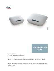
2.1<br />
Pre-configuring PC Setup<br />
Prior to the PB24M Series configuration, a computer with its<br />
Local Area Connection set to a static IP address is required to<br />
pre-configure the device (i.e. 192.168.1.XX).<br />
In order to do so, select the “Start” menu, “Control Panel” and<br />
then “Network Connections”. Right click on the “Local Area<br />
Connection” icon, choose “Properties”, and double click on the<br />
item “Internet Protocol (TCP/IP)” from the list as shown in the<br />
diagram below:<br />
An ‘Internet Protocol (TCP/IP) Properties’<br />
screen will pop up and set it as follows:<br />
Click the “OK” button to confirm the change.<br />
Now you are ready to start the first time<br />
configuration of the PB24M58.
3<br />
VLRM24/58<br />
Complete the following steps to configure a wireless link between a VLRM24/58 with a PB24M24/58:<br />
• Connect to the VLRM24/58 by opening a web browser and connecting to http://192.168.1.1.<br />
Login to the device using videolarm for the<br />
username and camera for the password.<br />
Click on the Network tab on the<br />
configuration page.<br />
Note that a static IP address of 192.168.1.1<br />
has been assigned to the unit be default.<br />
The default IP address, subnet mask, and<br />
gateway can all be changed from this screen<br />
if needed.<br />
Click in the corresponding box and enter in<br />
the required IP setting, then click the Change<br />
button in the bottom right hand corner of<br />
the window.<br />
NOTE - Connection to the VLRM24/58 will be lost if the IP address is changed at this time. A connection will need<br />
to be made to the new IP address that has just been assigned in order to view the configuration page again.<br />
3.1<br />
Wireless Configuration<br />
Click on the Wireless tab on the configuration page.<br />
Note that the unit is set to a Wireless Mode<br />
of Access Point and the default SSID for the<br />
wireless network is set to videolarm.<br />
The default SSID can be changed by clicking<br />
in the SSID box, typing in the new SSID that<br />
is required, and clicking on the Change button<br />
at the bottom right hand corner of the window.
3.2<br />
Wireless Security Options<br />
Encryption for the wireless link is also set from this page.<br />
Select the Encryption method that is desired<br />
and enter the appropriate encryption key. Note<br />
that this same key will need to be entered in<br />
all devices connecting to the wireless network.<br />
Click the Change button in the bottom right<br />
hand corner to apply the security settings.<br />
3.3<br />
VLRM24/58<br />
Complete the following steps to connect two VLRM58 units on the same wireless network using WDS.<br />
• Connect to the VLRM24/58 by opening a web browser and connecting to http://192.168.1.1.<br />
Login to the device using videolarm for the<br />
username and camera for the password.<br />
Click on the Network tab on the<br />
configuration page.<br />
Note that a static IP address of 192.168.1.1<br />
has been assigned to the unit be default.<br />
The default IP address, subnet mask, and<br />
gateway can all be changed from this screen<br />
if needed.<br />
Click in the corresponding box and enter in<br />
the required IP setting, then click the Change<br />
button in the bottom right hand corner of<br />
the window.<br />
NOTE - Connection to the VLRM24/58 will be lost if the IP address is changed at this time. A connection will need<br />
to be made to the new IP address that has just been assigned in order to view the configuration page again.
3.4<br />
Wireless Configuration<br />
Click on the Wireless tab on the configuration page.<br />
Note that the unit is set to a Wireless Mode<br />
of Access Point and the default SSID for the<br />
wireless network is set to videolarm.<br />
3.5<br />
Changing Wireless Mode<br />
Change the Wireless Mode to Access Point WDS.<br />
Place a check mark in the Auto box beside<br />
the selection.<br />
Connect to the second device and complete<br />
the proceeding steps.<br />
In most cases the units will connect to one<br />
another using the Auto mode. However this<br />
might not always be the case.<br />
If the units do not connect automatically then<br />
the MAC addresses for the devices will need<br />
to be entered into the WDS Peers section.<br />
The MAC address of the unit on the OPPOSITE<br />
end of the connection must be entered in the<br />
WDS Peers box.
The MAC address for each unit can be located<br />
on the Main tab where it shows the units<br />
status. There MAC address can be found in<br />
three separate locations on that screen under<br />
LAN MAC, WAN MAC, and AP MAC. All three<br />
MAC address will be the same.<br />
Log into each unit, take note of the listed MAC address, and enter it into the WDS Peers box on the other unit.<br />
The default SSID can be changed by clicking in the SSID box, typing in the new SSID that is required, and clicking<br />
on the Change button at the bottom right hand corner of the window.<br />
Encryption for the wireless link is also set<br />
from this page.<br />
Select the Encryption method that is desired<br />
and enter the appropriate encryption key. Note<br />
that this same key will need to be entered in<br />
all devices connecting to the wireless network.<br />
Click the Change button in the bottom right<br />
hand corner to apply the security settings.<br />
4<br />
PB24M24/58<br />
• Connect to the PB24M24/58 by opening a web browser and connecting to http://192.168.1.100.<br />
Login to the device using videolarm for the<br />
username and camera for the password.<br />
Click on the Network tab on the<br />
configuration page.<br />
Note that a static IP address of 192.168.1.100<br />
has been assigned to the unit be default.<br />
The default IP address, subnet mask, and<br />
gateway can all be changed from this screen<br />
if needed.<br />
Click in the corresponding box and enter in<br />
the required IP setting, then click the Change<br />
button in the bottom right hand corner of<br />
the window.<br />
NOTE - Connection to the PB24M24/58 will be lost if the IP address is changed at this time. A connection will need<br />
to be made to the new IP address that has just been assigned in order to view the configuration page again.
4.1<br />
Wireless Configuration<br />
Click on the Wireless tab on the configuration page.<br />
Note that the Wireless mode for this unit is<br />
set to Station and the default SSID for the<br />
wireless network is set to videolarm.<br />
The default SSID can be changed by clicking<br />
on the Select button next to the SSID box.<br />
A new window will appear that will show<br />
all of the wireless networks within range of<br />
the device.<br />
Select the required SSID (if it was changed in<br />
the previous steps), and click on the Select<br />
button at the bottom right hand corner of<br />
the window.<br />
4.2<br />
Wireless Security Options<br />
Encryption for the wireless link is also set from the main Wireless configuration page.<br />
Select the Encryption method that is desired<br />
and enter the appropriate encryption key. Note<br />
that this same key will need to be entered in<br />
all devices connecting to the wireless network.<br />
Click the Change button in the bottom right<br />
hand corner to apply the security settings.
5<br />
Adding Multiple PB24M Series Devices to a Wireless Network<br />
By default each PB24M Series is configured with the<br />
IP address of 192.168.1.100. If there is more than one<br />
PB24M58 on the wireless network, then you will need to<br />
change the default IP addresses on each additional device.<br />
For example Unit 1 could retain the default IP address of<br />
192.168.1.100. Unit 2 would need to have its address<br />
changed, so it could have 192.168.1.101 assigned to the<br />
Network Configuration. Unit 3 could have addresses of<br />
192.168.1.102, and so on for each additional device.<br />
PB24M58 IP CONFIGURATION<br />
NOTE – When configuring multiple PB24M Series devices<br />
for the first time, make sure that only one device is<br />
powered on at a time. Powering on two devices with a<br />
default configuration will cause IP address conflicts on<br />
a network since each of the devices will have the same<br />
addresses assigned to their interfaces.<br />
5.1<br />
Changing the Default SSID<br />
The default SSID for the PB24M58 is Videolarm. If the SSID needs to be changed from the default, then the SSID<br />
must be changed on ALL wireless devices in the network on all VLRM58 and PB24M58 devices.
Wireless IP & Mac Address Form<br />
For your convenience and future reference, the following form has been included to record your wireless surveillance systems IP and Mac addresses. Once<br />
completed, remove the form from instruction packet and place in a secure place or inside the Moog Videolarm wireless product. The information recorded will prove<br />
beneficial when servicing or expanding your wireless system.<br />
Camera # IP Address Mac Address Location Password Notes<br />
1<br />
1<br />
192.168.1.101<br />
00-65-29-12-12<br />
Parking1<br />
Root<br />
Megapixl Cam<br />
2<br />
3<br />
4<br />
5<br />
6<br />
7<br />
8<br />
9<br />
10<br />
11<br />
12<br />
Wireless # IP Address Mac Address Location BSSID Mode<br />
1<br />
192.168.1.1 00-08-d3-12-d2 Parking1 Videolarm Client ch 11<br />
1<br />
2<br />
3<br />
4<br />
5<br />
6<br />
7<br />
8<br />
9<br />
10<br />
11<br />
12