A Low-Noise Thermistor Bridge for Use in ... - Clinical Chemistry
A Low-Noise Thermistor Bridge for Use in ... - Clinical Chemistry
A Low-Noise Thermistor Bridge for Use in ... - Clinical Chemistry

You also want an ePaper? Increase the reach of your titles
YUMPU automatically turns print PDFs into web optimized ePapers that Google loves.
CLIN. CHEM. 20/8, 1009-1012 (1974)<br />
A <strong>Low</strong>-<strong>Noise</strong> <strong>Thermistor</strong> <strong>Bridge</strong> <strong>for</strong> <strong>Use</strong> <strong>in</strong> Calorimetry<br />
Robert L. Berger,’ Walter S. Frlauf,2 and Horace E. Cascio2<br />
A precision thermistor bridge and thermistor is described<br />
<strong>for</strong> use <strong>in</strong>a thermaltitration calorimeteror a<br />
high-speed stopped- or cont<strong>in</strong>uous-flow calorimeter of<br />
the Roughton type. These are compared and evaluated<br />
with regard to several other types of detectors, <strong>in</strong>clud<strong>in</strong>g<br />
the plat<strong>in</strong>um resistance thermometer, thermocouple,<br />
transistor thermometer, and capacitance thermometers.<br />
At this time the best detection <strong>for</strong> our purpose<br />
seems to be a specially constructed 20- 100 kfI thermistor<br />
used <strong>in</strong> conjunction with a new ac lock-<strong>in</strong> amplifier<br />
bridge. The sensitivity of the system is equivalent to a<br />
peak-to-peak noise of 25 X 106 #{176}C, witha 100-ms<br />
time constant and 1 W power dissipation <strong>in</strong> the thermistor.<br />
Long-term drift of the bridge, without an oven, was<br />
1 X 10⁻⁶ #{176}C/m<strong>in</strong>.<br />
Precisiontemperature-measurement has traditionally<br />
been done with thermocouples or plat<strong>in</strong>um thermometers<br />
(1). Recently there has been <strong>in</strong>creased <strong>in</strong>terest<br />
<strong>in</strong> thermistors (2), capacitive sensors (3), and<br />
transistor sensors (4). <strong>Thermistor</strong>s have been limited<br />
by long-term <strong>in</strong>stability, and noise well <strong>in</strong> excess of<br />
the theoretical thermal agitation noise. These problems<br />
are now be<strong>in</strong>g solved by improvements, and<br />
thermistors appear very attractive <strong>for</strong> many purposes<br />
(2).<br />
This paper discussesthe meritsof thermistorsrelative<br />
to other techniques, reviews the calculation of<br />
signal-to-noise (S/N) ratio, and describes optimum<br />
application to the measurement of very small but<br />
rapid temperature changes <strong>in</strong> chemical k<strong>in</strong>etic experiments<br />
(5), where self-heat<strong>in</strong>g must be held to a very<br />
low level. The measurement system is also well suited<br />
toevaluationofthermistorcharacteristics.<br />
National Institutes of Health, Public Health Service, U. S. Department<br />
of Health, Education and Welfare, Bethesda, Md. 20014.<br />
1 Laboratory of Technical Development, National Heart and<br />
Lung Institute.<br />
2 Division of Research Services.<br />
Received April 4, 1974; accepted May 27, 1974.<br />
Measurement with a thermistor is basically the<br />
same as with a plat<strong>in</strong>um thermometer, and the same<br />
basic configurationis appropriate, namely, an ac<br />
bridge<strong>in</strong> which the sensorisone arm, followed by a<br />
lock-<strong>in</strong>amplifier.The use of ac elim<strong>in</strong>atesthe effect<br />
ofchang<strong>in</strong>g thermal emf’sand amplifierdrift,and allows<br />
amplification at a frequency free from low-frequency<br />
noise.<br />
The<br />
<strong>Bridge</strong><br />
The ma<strong>in</strong> advantages of a thermistorare its high<br />
temperature coefficientand high resistance.The latter<br />
permits direct coupl<strong>in</strong>g, with a near-optimum<br />
noise figure, and also decreases problems with parasitic<br />
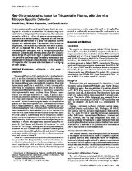
series resistance. A block diagram of the bridge is<br />
shown <strong>in</strong> Figure 1. The basic bridge is a standard<br />
Wheatstone type. Assum<strong>in</strong>g that R2 = R3, the bridge<br />
is balanced by adjust<strong>in</strong>g R1 to be equal to R. The<br />
output e0 result<strong>in</strong>gfrom a small change <strong>in</strong> R willbe<br />
f R + E - 1/2 E<br />
e0 = t\ 2R +<br />
4 R<br />
E<br />
= - x (T.C.) X T<br />
where (T. C.) is the temperature coefficient and zT<br />
the temperaturechange.<br />
The thermal noiseof the left side of the bridge can<br />
be made negligible compared to that of the right side<br />
by simply mak<strong>in</strong>g R2 10-foldsmallerthan the thermistor<br />
resistance. The noise signal will be essentially<br />
that of the rightside, with an equivalent resistance<br />
R/2. There<strong>for</strong>e e = V2kTBR <strong>in</strong> voltsr.m.s.,where<br />
k is Boltzmann’s constant,T is the absolute temperature,<br />
and B is the bandwidth. The signal-to-noise<br />
ratio is<br />
CLINICAL CHEMISTRY. Vol. 20. No.8. 1974 bOa
CAUeNATION<br />
UNSALANCE<br />
P$AS(<br />
ADJUST<br />
Fig. 1. Block diagram of the bridge<br />
e0/e5 = 4\I2kTBR x (T.C.) X T<br />
This is more illum<strong>in</strong>at<strong>in</strong>g when the power dissipation<br />
<strong>in</strong>the thermistoris<strong>in</strong>troduced.This is<br />
- (E/2)2<br />
- R<br />
Substitut<strong>in</strong>g<strong>in</strong>the equation above then gives<br />
e0/e5 = 1/2 /2kTB x (T. C.) x T<br />
S<strong>in</strong>ce this is <strong>in</strong>dependent of R, the thermistor can be<br />
selected to optimize the noise figure of the amplifier.<br />
A value on the order of 20kl to 200kl will result <strong>in</strong> a<br />
negligible noise contribution from modern solid-state<br />
amplifiers, and is consistent with thermistor fabrication<br />
capabilities.<br />
The equation above relates signal change to the<br />
r.m.s. value of the noise. Usually the peak-to-peak<br />
value of noise, about six times greater, will be the<br />
more appropriate figure to use. Then the S/N ratio is<br />
about (Y17)-sfP/kTB (T.C.) T or, equivalently,<br />
the temperature change needed to give an output<br />
equal to peak-to-peak noise is<br />
17/<br />
With a T. C. of 4% per degree Celsius, a thermistor<br />
power of 1 zW, a bandwidth of about 1.5 Hz (correspond<strong>in</strong>g<br />
to a time constant of 0.1 s), and T near<br />
room temperature, the calculated value of iT is<br />
about 25 X 10-6 #{176}C.<br />
Stray capacitanceof the thermistorand the cable<br />
appears <strong>in</strong> parallelwith R and must be balanced to<br />
avoid overload<strong>in</strong>gthe synchronous detector; coarseand<br />
f<strong>in</strong>e-trimmer capacitors <strong>in</strong> parallel with R1 serve<br />
thispurpose. When the bridge is balanced, e0 has<br />
components hav<strong>in</strong>g the orig<strong>in</strong><strong>in</strong> both the resistive<br />
and capacitivelements.Both components areout of<br />
phase with E, but they are always at 90#{176} to each<br />
other.There<strong>for</strong>e,when the referencephase to the<br />
synchronous detectorisproperlyadjusted,itwillbe<br />
<strong>in</strong> phase with the resistive component while caus<strong>in</strong>g<br />
the capacitivecomponent to be completely rejected,<br />
so that small changes <strong>in</strong> capacitance will not cause<br />
any output.<br />
The frequencyshouldbe as low as possibleto m<strong>in</strong>imize<br />
the capacitive reactances, yet should be high<br />
enough to place the signal spectrum well out of the<br />
low-frequency noise region and to providethe desired<br />
bandwidth afterfilter<strong>in</strong>gthe second harmonic signal<br />
out of the detector.For thissystem a m<strong>in</strong>imum time<br />
constantof 1 ms was desired,correspond<strong>in</strong>gto a pass<br />
band ofabout 150 Hz. A modulation frequencyof 500<br />
Hz was selectedtomeet the above requirements.<br />
Long-term stabilitydepends on the stabilityofthe<br />
bridgeelements and strayadmittances.<strong>Bridge</strong> resistors<br />
should have temperature coefficients of 2 or 3<br />
ppm/#{176}C near room temperature. Variable bridge resistors<br />
should consist of coarse and f<strong>in</strong>e potentiometers,<br />
with the smallest total value that will accommodate<br />
the range of thermistor tolerances and temperature<br />
encountered. The calibrat<strong>in</strong>g resistors have so<br />
littleffectthat theirtoleranceis immaterial.For<br />
maximum long-termstability, the bridge, other than<br />
R could be placed<strong>in</strong> a temperature-controlledoven,<br />
althoughthatwas not done <strong>for</strong>this<strong>in</strong>strument.<br />
High-resistancethermistors virtually elim<strong>in</strong>ate<br />
trouble from series resistance, but shunt conductance,<br />
ma<strong>in</strong>ly <strong>in</strong> the cable to the thermistor, must be<br />
kept extremely low. Teflon <strong>in</strong>sulation is ideal to take<br />
care of this.Good shield<strong>in</strong>gisalsoessential,so that<br />
pick-up willnot be high enough to cause overloadbe<strong>for</strong>e<br />
be<strong>in</strong>g rejected by the synchronous detector.<br />
Several resistors and a pushbutton permit chang<strong>in</strong>g<br />
a bridge resistor the same fractional amount that<br />
R will change when heated 1 X i0 #{176}C, assum<strong>in</strong>g a<br />
temperaturecoefficient of -4% per degreeCelsius<strong>for</strong><br />
the thermistor.<br />
With a 100kl thermistorthat we used,the source<br />
resistance is 50k0. With this value, at 500 Hz, either<br />
bipolar or field effect transistors can have a noise figure<br />
of less than 2 db, so that the S/N ratio of the<br />
bridge, calculated above, will be essentially realized<br />
<strong>for</strong>the entire<strong>in</strong>strument;thisisverifiedby testresults.<br />
Our unit has a low-noise FET op amplifier, but<br />
if pick-up problems are severe, a lower value thermistorwith<br />
a bipolar op amplifier might be better.<br />
The bridge isdirectcoupled to the firstamplifier<br />
stagewith negativefeedback to the fixedsideof the<br />
bridgeto setthe sensitivity<strong>in</strong>dependent of thermistor<br />
value. Follow<strong>in</strong>g this, the signal is ac coupled, further<br />
amplified, and band limited with an active filter.<br />
An L-C filter was found to be unsatisfactory because<br />
of a slight<strong>in</strong>ductanceshiftwith signal-level change<br />
as the bridgemoves offbalance.This resulted<strong>in</strong> an<br />
unwanted output signal if any capacitive unbalance<br />
existed, because of the result<strong>in</strong>g phase shift.<br />
Synchronous detectionis per<strong>for</strong>med by a monolithic<br />
multiplier. This is another po<strong>in</strong>t of possible<br />
long-term drift. The effect of multiplier drift can be<br />
1010 CLINICAL CHEMISTRY. Vol. 20. No. 8, 1974
decreasedat willby <strong>in</strong>creas<strong>in</strong>g the ga<strong>in</strong> ahead of the<br />
multiplier,but thisalsodecreasesthe range of signal<br />
and pickup that can be handled without overload, so<br />
that a low-drift multiplier is desirable.<br />
Follow<strong>in</strong>g the detectoris a low-pass filterwith<br />
switch-selectable time constantsof 1,10,or 100 ms,<br />
and a dc amplifier with ga<strong>in</strong> switch<strong>in</strong>g <strong>in</strong> decade<br />
steps.<br />
In addition,the unit <strong>in</strong>cludesa s<strong>in</strong>e-waveoscillator,<br />
reference-phase-adjust network, test po<strong>in</strong>ts, provision<br />
<strong>for</strong> monitor<strong>in</strong>g bridge balance, etc. These are<br />
all rout<strong>in</strong>efeaturesof a good lock-<strong>in</strong>amplifier, and<br />
willnot be discussed<strong>in</strong>detail.<br />
The<br />
<strong>Thermistor</strong><br />
The thermistorshave been speciallybuilt<strong>for</strong>us by<br />
a commercial firm (6) with long experience (2) <strong>in</strong> the<br />
manufactur<strong>in</strong>g of very quiet, stable thermistors.<br />
These units were beads made of copper oxide-free<br />
materials,hermeticallysealed<strong>in</strong>glassand aged.Sizes<br />
ofthe f<strong>in</strong>alunitvary from 0.0125 cm to 0.025cm. The<br />
leadsare 25-im nickelwires,attached to the plat<strong>in</strong>um<br />
wire from the beads, with Teflon <strong>in</strong>sulation.<br />
This is sealed with epoxy <strong>in</strong> the end of a 0.08 cm<br />
(o.d.)by 2.5cm hypodermic sta<strong>in</strong>less-steel tube.The<br />
nickelwire isthen attachedto 36-gauge copper leads<br />
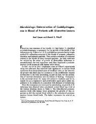
and the whole encapsulated <strong>in</strong> a 0.25-cm sta<strong>in</strong>lesssteeltube.Figure<br />
2 shows the thermistorunitas itis<br />
used <strong>in</strong> our thermal titrationcalorimeter(7).For<br />
most purposes a coat<strong>in</strong>gofpolyv<strong>in</strong>ylchloride over the<br />
sta<strong>in</strong>lessteelis adequate protection,but <strong>for</strong> blood<br />
work KEL-F dispersion (8) dip is applied, giv<strong>in</strong>g a<br />
25-50 m coat<strong>in</strong>g, free of p<strong>in</strong>-holes. Response times<br />
have been checked as describedpreviously(9)and<br />
agree with our theoreticalcalculations.These run<br />
from 2.5 ms <strong>for</strong> the base unitsto 10-25 ms <strong>for</strong> the<br />
KEL-F coated units. Other coat<strong>in</strong>gs are under <strong>in</strong>vestigation<br />
that may be blood compatible and still have<br />
a fastresponse time. For the thermal titration unit,<br />
0.1s isadequate.<br />
Experimental Procedure<br />
The unitwas tested<strong>in</strong> the labwith a 100kf, 0.01%<br />
precisionresistorsubstituted<strong>for</strong>the thermistor.The<br />
resistorwas connected to an 18-<strong>in</strong>chcable and enclosed<br />
<strong>in</strong> a styrofoam box. Output noise and drift<br />
were compared to the 1 X 10 #{176}C calibration step<br />
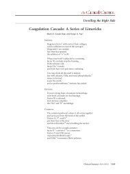
caused by the pushbutton. The results are shown <strong>in</strong><br />
Figure 3. The observed noise with the 100 ms time<br />
constant was about 25 X 10-6 #{176}C peak-to-peak,as<br />
calculated,and it<strong>in</strong>creasedby a factorofabout three<br />
with each factorof 10 decrease <strong>in</strong> time constant, as it<br />
should. The drift, after several hours warm-up, was<br />
about 1 X 10⁶ #{176}C/m<strong>in</strong>, as shown <strong>in</strong> Figure 4, which<br />
was adequate <strong>for</strong> immediate requirements, and could<br />
probably be decreased if necessary, as discussed<br />
above. The ma<strong>in</strong> source isprobably R1, which consistsof<br />
a 50k11precisionresistor<strong>in</strong> serieswith lOOkQ<br />
and 10kg potentiometerswith dial<strong>in</strong>dicators.This is<br />
very convenient,as thermistorsfrom 50k11to 160kl<br />
O.03Z’<br />
Fig. 2. <strong>Thermistor</strong> <strong>in</strong> sta<strong>in</strong>less steel tube coated with KEL-F<br />
lOOk<br />
10 tOO<br />
J ‘( i m#{149}<br />
100<br />
- -<br />
m..<br />
TIME CONSTANT FILTER (ma)<br />
Fig. 3. Sensitivity and time response<br />
LONG-TERM<br />
3OMIN.<br />
DRIFT<br />
Fig. 4. Temperaturedrift<br />
can be accommodated and the valueofR can be read<br />
from the potentiometerdials. However, <strong>for</strong> the maximum<br />
stability, the adjustableportionof R should be<br />
much smaller.<br />
Discussion<br />
These figures are substantially better than those<br />
reported <strong>for</strong> other techniques. Plat<strong>in</strong>um thermometers<br />
have a much lower temperature coefficient, giv<strong>in</strong>g<br />
a lower source signal-to-noise ratio, and require a<br />
much more elaborate sens<strong>in</strong>g system to avoid serious<br />
additional degradation of S/N ratio. Thermocouples<br />
can easily atta<strong>in</strong> better source S/N ratios than thermistors<br />
operated at the 1-1zW level by gett<strong>in</strong>g the resistance<br />
down to a few ohms. However, the voltage is so<br />
low that it is not possible at present to amplify the<br />
signal without drastic decrease <strong>in</strong> S/N ratio. This is<br />
because the signal is dc, so that impedance trans<strong>for</strong>mation<br />
by a trans<strong>for</strong>mer is impossible unless the signal<br />
is chopped, and sufficiently low noise chopp<strong>in</strong>g is<br />
difficult. There is also the problem of temperature<br />
control of the reference junction and other junctions.<br />
CLINICAL CHEMISTRY. Vol. 20. No. 8. 1974 1011
Transistorsensorshave an <strong>in</strong>herentsensitivityof<br />
about 2 mV/#{176}C, so the sourceS/N ratiodepends on<br />
the equivalent<strong>in</strong>put noise voltage. Un<strong>for</strong>tunately,<br />
this<strong>in</strong>creasesas frequency decreases,and operation<br />
otherthan dc isnot attractive. A good low-noisetransistormay<br />
have about 5 nV r.m.s.//II equivalent<br />
<strong>in</strong>putnoiseat 10 Hz. This isequivalentto about 15 X<br />
10-6 #{176}C peak-to-peak//T1, which iscomparable to<br />
that of the thermistor,particularly<strong>for</strong> rapid measurements<br />
where more of the signal spectrum is at<br />
higher frequencies. However, it might be hard to <strong>in</strong>corporate<br />
a transistor <strong>in</strong> a suitable probe, and results<br />
reported to date <strong>in</strong>dicate realization of only about 1<br />
x i0 #{176}C resolutionata power levelofabout 5 fLW.<br />
Reactive transducers are attractivebecause of<br />
their freedom from thermal noise with about the<br />
same easeof use as thermistors, as wellas the possibilities<br />
of substantially shorter time constants (3).<br />
The S/N ratio theoretically atta<strong>in</strong>able is proportional<br />
to Q (the ratio of peak stored energy to energy dissipated<br />
per cycle) of the device, and to the temperature<br />
coefficient of the capacitance. Un<strong>for</strong>tunately, <strong>for</strong> useful<br />
sensors fabricated so far, the latter has tended to<br />
be 10-foldlower than the T.C. of thermistors,thus<br />
largelyoffsett<strong>in</strong>gthe benefitsresult<strong>in</strong>gfrom the<br />
valuesof Q that have been achieved. In addition, the<br />
measurement circuitry is somewhat more complicated,<br />
and it can be anticipated that the practical difficulties<br />
<strong>in</strong> approach<strong>in</strong>g the theoretical possibilities<br />
would be considerable, as has been the case with<br />
parametric op amplifiers.<br />
Consider<strong>in</strong>g this briefreview of alternatives,we<br />
th<strong>in</strong>k thatthe thermistorisprobablythe presentdevice<br />
of choice <strong>for</strong> precision temperature measurement,<br />
although further confirmation of long-term<br />
stability is needed.<br />
We acknowledge the helpful comments by H. H. Plumb and of<br />
the Temperature Section, Heat Division, Institute of Basic Standards,<br />
National Bureau of Standards, and Mr. Meyer Sapoff of<br />
Thermometrics, who fabricated the thermistors. Special thanks<br />
are due B. Balko, Department of Physics, Boston University, who<br />
checked the response times, and calculations of the thermistor response<br />
times.<br />
References<br />
1. Cutkotsky, R. D., An A-C resistance thermometer bridge. J.<br />
Res. Nat. Bur. Stand. 74C, 15 (1970).<br />
2. Sapoff, M., <strong>Thermistor</strong>s <strong>for</strong> biomedical use. In Temperature,<br />
Its Measurement and Control <strong>in</strong> Science and Industry 4, Part 3, p<br />
2109, ISA (1972).<br />
3. Maserjian, J., Th<strong>in</strong>-film temperature sensor. In Temperature,<br />
Its Measurement and Control <strong>in</strong> Science and Industry 4, Part 3, p<br />
2159, ISA (1972).<br />
4. Pease, R. A., Us<strong>in</strong>g semiconductor sensors <strong>for</strong> l<strong>in</strong>ear thermometers.<br />
Inst rum. Contr. Syst. 45, 80 (1972).<br />
5. Balko, B., and Berger, R. L., Stopped-flow calorimetry <strong>for</strong> biochemical<br />
reactions. Anal. Ghem. 41, 1506 (1969).<br />
6. Thermometrics, Inc., 15 Jean Place, Edison, N. J. 08817.<br />
7. Watt, D., Berger, R. L., Green D., and Mar<strong>in</strong>i, M. A., Thermal<br />
titration: Application of calorimetry to the study of plasma coagulation.<br />
GUn. Chem. 20, 1013 (1974).<br />
8. KEL-F Dispersion, 3-M, M<strong>in</strong>neapolis, M<strong>in</strong>n.<br />
9. Berger, R. L., azd Balko, B., Thermal sensor coat<strong>in</strong>gs suitable<br />
<strong>for</strong> rapid response, biomedical applications. In Temperature, Its<br />
Measurement and Control <strong>in</strong> Science and Industry 4, Part 3, p<br />
2169, ISA (1972).<br />
1012 CLINICAL CHEMISTRY, Vol. 20, No.8, 1974