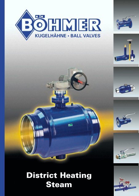
District Heating Steam - boehmer.de
District Heating Steam - boehmer.de District Heating Steam - boehmer.de
District Heating Steam
- Page 2 and 3: Range of application • District h
- Page 4 and 5: Comparison District Heating Ball Va
- Page 6 and 7: Because of the low pressing between
- Page 8 and 9: Ball valve with welded ends for und
- Page 10 and 11: Ball valve with welded ends, standa
- Page 12 and 13: Ball valve with flanged ends, full
- Page 14 and 15: Ø DA Spot drill ball valve, full b
- Page 16 and 17: Ball valve with flanged and welded
- Page 18 and 19: Ball valve with detachable welded e
- Page 20 and 21: Accessories for ball valves for und
- Page 22 and 23: Actuators for ball valves Levers Ge
- Page 24: Please ask for our Product Range, D
<strong>District</strong> <strong>Heating</strong><br />
<strong>Steam</strong>
Range of application<br />
• <strong>District</strong> heating pipeline systems<br />
• Un<strong>de</strong>rground installations<br />
• Cold embedding<br />
• Chamber installation<br />
• Vent and drain valves<br />
• Spot-drill ball valves<br />
• Tie-in ball valves<br />
• Utility connection<br />
• <strong>Steam</strong><br />
Company´s Profile<br />
Foun<strong>de</strong>d: . . . . . . . . . . . . . . . . .1956, Family-owned business<br />
Managing Director: . . . . .Dr. Ing. Thomas Böhmer<br />
Employees: . . . . . . . . . . . . . . .250<br />
Annual Turnover: . . . . . . . .60 million DEM<br />
Manufacturing area: . . . .25.000 m 2 main plant Sprockhövel<br />
4.500 m 2 subsidiary plant Hattingen<br />
Total number of<br />
ball valves produced: > 20 million<br />
Approvals<br />
• DIN EN ISO 9001 • API 6D<br />
• GOST • DIN-DVGW<br />
• Structural component approval • ÖVGW<br />
• SVGW<br />
• AD-HP O (TÜV)<br />
• BAM<br />
Technological approval/welding:<br />
• TRD 201 • AD-HP 2/1 (TÜV)<br />
• DIN EN 729<br />
AGFW
Standard BÖHMER-<strong>District</strong> <strong>Heating</strong> Ball Valve<br />
• Structural component approved<br />
• Fully wel<strong>de</strong>d <strong>de</strong>sign<br />
• Pressurable from both si<strong>de</strong>s<br />
• Starting from DN125, PN16 trunnion mounted ball,<br />
starting DN65, PN40 „Double Block and Bleed“-<strong>de</strong>sign<br />
• Compact <strong>de</strong>sign<br />
• Long service life<br />
• Maintenance free<br />
• Full and reduced bore<br />
• Body material ma<strong>de</strong> of forged steel (3.1.B material)<br />
• Determination of the welding seams according to the<br />
valid rules for pipeline and pressure vessel production<br />
• Low torque<br />
• Suitable for cold embedding/compensationless<br />
low <strong>de</strong>pth un<strong>de</strong>rground installation<br />
• Higher resistance to corrosion than the pipeline<br />
system due to the more massive wall thickness<br />
of the ball valves<br />
• Lowest temperature and pressure drops<br />
• Thermal resistance of the sealing system<br />
• Chambered sealing system<br />
• Self-adjusting sealing system in case of wear and tear<br />
• Replaceable sealing elements at the stem<br />
• Variable plug-in system for stem extensions<br />
Technical Data<br />
• Diameter: DN6 to 900 ( 1 ⁄4“-36“), up to<br />
1.500 (60“) on request<br />
• Pressure range: up to PN63 (up to ANSI class 400)<br />
• Temperature range: up to +250°C (482°F)<br />
district heating and steam<br />
• Face-to-face dimensions: up to 2000mm<br />
• Stem extensions: up to 3000mm<br />
• Body material: Carbon steel RST 35.8/ ST 52.0,<br />
TSTE 355 (ASTMA 350 LF2)<br />
• Ball material: Stainless steel (standard up to<br />
DN400/16“),Nickelplated carbon<br />
steel (standard ≥DN 500/20“),<br />
optional stainless steel<br />
• Stem: Stainless steel<br />
• Sealing material: PTFE, EPDM, special material<br />
for high temperatures
Comparison <strong>District</strong> <strong>Heating</strong> Ball Valve<br />
D<br />
G<br />
A: Top of stem<br />
BÖHMER district heating ball valve<br />
The top of the stem is squared. At the front it has an<br />
indicator for the flow direction. In addition, the stem<br />
has a groove milled into it. Its purpose is the fixing<br />
of stem extension or square adapters without confusion.<br />
(Picture1)<br />
Competitors´ <strong>de</strong>sign<br />
The top of the stem is squared or ma<strong>de</strong> as a hexagon.<br />
B: Stem extensions<br />
Comparison Böhmer Ball Valve<br />
vs. competitors´ <strong>de</strong>sign<br />
A<br />
B<br />
D<br />
C<br />
F<br />
BÖHMER Ball Valve<br />
A<br />
C<br />
Competitors´ <strong>de</strong>sign<br />
Note:<br />
The competitors´ <strong>de</strong>sign <strong>de</strong>scribed herein for comparison<br />
is a ball valve <strong>de</strong>sign ma<strong>de</strong> of pressed pipe material.<br />
For testing purposes such ball valves have been produced<br />
by Böhmer, too. Variations in some technical features<br />
of the ball valves of other manufacturers may occur.<br />
BÖHMER district heating ball valve<br />
The top si<strong>de</strong> of the stem extension has a dihedron<br />
that is used for fixing of the plug in adapter flange as<br />
well as it is indicating the position of the valve un<strong>de</strong>rground.<br />
D<br />
B<br />
E E G<br />
F<br />
The surfaces of the dihedron are parallel to the middle<br />
axis of the ball valve. This is important if position and<br />
alignment of the ball valve un<strong>de</strong>rground are unknown.<br />
The position of the indicator of flow direction in accordance<br />
to the dihedron <strong>de</strong>termines exactly wether the<br />
ball valve is opened or closed. (Picture 1).<br />
The upper parts of the stem extension are normally<br />
exposed to the weather influences. For that reason<br />
every protecting tube has a special epoxy coating at<br />
the upper section that prevents any form of corrosion.<br />
(Picture 2)<br />
Picture1: Stem Picture 2: Protection tube stem<br />
inclu<strong>de</strong>d with stop pins<br />
Competitors´ <strong>de</strong>sign<br />
The position of the ball valve un<strong>de</strong>rground cannot<br />
be located.<br />
The upper sections of the protection tube are not<br />
especially protected against corrosion.<br />
Some manufacturers weld in stainless steel parts in<br />
this area with all the problems related to connections<br />
between carbon and stainless steel.<br />
C: Stops limiting the switching angle<br />
The stops of the stem can be loa<strong>de</strong>d with the full<br />
torque if wrong handling occurs. That means that<br />
the minimum requirements have to be a sufficient<br />
dimensioning or the exchangeability of the stops.<br />
Normally, the exchangeability means that the<br />
stops are moved in very dirty condition during<br />
switching due to the fact that they are installed<br />
without cover.<br />
Experience shows that dirt can get between the<br />
body and the stops and could prevent the ball<br />
from reaching its end position.<br />
If the ball is in almost closed position media can<br />
flow through the remaining gap between sealing<br />
and ball. This can damage the seals.<br />
BÖHMER district heating ball valve<br />
Böhmer uses stops installed insi<strong>de</strong> being resistant to<br />
damage and dirt. (Picture 2)<br />
Competitors´ <strong>de</strong>sign<br />
The stop is an outsi<strong>de</strong> mounted split-pin only.
D: Stem Sealing System<br />
BÖHMER district heating ball valve<br />
The sealing of the stem is ma<strong>de</strong> by a redundant<br />
system. The first system seals directly at the body<br />
of the ball valve and so within the insulation of the<br />
pipeline system. It prevents hot water from entering<br />
the stem extension and so avoids unnecessary<br />
loss of temperature as well as corrosion.<br />
The sealing system consists of two temperature<br />
and pressure proof O-rings with an additional, prestressed<br />
PTFE packing.<br />
A second i<strong>de</strong>ntical sealing system is located in the<br />
upper section of the stem extension. It is completely<br />
exchangeable and is additionally used for<br />
support of the stem.<br />
Competitors´ <strong>de</strong>sign<br />
The sealing is only at the upper section of the stem<br />
extension and ma<strong>de</strong> by O-rings only. This leads to<br />
unnecessary temperature loss at the stem extension<br />
as well as possible corrosion because of the<br />
missing sealing at the lower part.<br />
E: Weld seams<br />
In principle, stress crack corrosion at load transmitting<br />
weld seams has to be avoi<strong>de</strong>d.<br />
This can be done by either welding through when<br />
welding V-seams or by applying counter weld seams<br />
that prevent corrosive media from entering a possible<br />
gap and that absorb the bending moment of a<br />
one si<strong>de</strong>d weld seam.<br />
BÖHMER district heating ball valve<br />
The welding seams are flawless wel<strong>de</strong>d through<br />
the whole profile and have no cracks or lack of<br />
fusion. The residual stress is minimized due to<br />
“free“ shrinking of the ball valve during welding<br />
Therefore, the weld seams meet the requirements<br />
of the valid process approvals of the pipeline and<br />
pressure vessel producing industries. (Picture 3)<br />
Picture 3: Welding seam Böhmer Ball Valve<br />
Competitors´ <strong>de</strong>sign<br />
Due to the shape of a body ma<strong>de</strong> of cold formed<br />
pipe material the body fillet weld cannot be wel<strong>de</strong>d<br />
through or counter wel<strong>de</strong>d.<br />
In addition, these types of weld seams have very high<br />
residual stress. (Picture 4)<br />
Picture 4: Welding seam of competitors´ <strong>de</strong>sign<br />
F: Sealing system at the passage<br />
Changes in the temperature as well as the pressure of<br />
the flow media lead to <strong>de</strong>formation of all parts of a<br />
valve. The sealing system between ball and body has<br />
to be capable to compensate this change of dimensions.<br />
In addition, the pressurization of the ball by the<br />
flow media leads to a force that has to be borne by<br />
the sealing system.<br />
Since the loading force of the ball to the seats increases<br />
quadraticly to the diameter insi<strong>de</strong> the ball, already at<br />
DN150/6“ and PN16/ANSI class 150the charge at the<br />
seals as well as the torque and the wear is so high,<br />
that the ball shall be trunnion mounted.<br />
(AGFW/FVGW-rules, working sheet FW 410 - part 5,<br />
edition February 1999)<br />
BÖHMER district heating ball valve<br />
In principle, Böhmer ball valves have trunnion mounted<br />
balls starting from DN150/6“ and PN16/ANSI class<br />
150(for pressures higher than PN16/ANSI class 150<br />
for smaller diameters too).<br />
The sealing is <strong>de</strong>signed according to the double block<br />
and bleed principle (Picture 5). The seat acts as a differential<br />
piston. If the ball valve is closed pressure<br />
builds up at the O-ring that is integrated at the outer<br />
diameter of the seat ring. This moves the seat ring<br />
against the trunnion mounted ball. For small pressure<br />
differences spring packages support the pressing.<br />
Coil spring packages are used having a longer service<br />
life and significant higher spring excursion than disc<br />
springs. The trunnion mounted ball takes up the load<br />
resulting from the pressure charging the ball.<br />
Example:<br />
Diameter DN200/8“ and working pressure PN25/<br />
ANSI class 300. This results in an axial force on the<br />
ball of 315 kN. (32 tons)
Because of the low pressing between ball and sealing<br />
no <strong>de</strong>formation occurs at the sealing if the ball is<br />
trunnion mounted, the wear due to possible dirt<br />
between ball and seat is minimized.<br />
Even if wear occurs due to dirt in the flow media the<br />
self-adjusting sealing system can compensate this.<br />
The complete sealing system including the spring<br />
packages is completely chambered in the body and<br />
thus prevented from dirt. Therefore, functionality is<br />
given at any time.<br />
Picture 5: Böhmer-Sealing system, „Double-Block and Bleed“ principle<br />
with trunnion mounted ball.<br />
1. Operational case:<br />
Inlet pressure is higher than body or outlet pressure<br />
The O-ring goes into position 1 and the access pressure<br />
moves with the piston surface (dda2 – da2)*π/4<br />
the seat onto the ball. Due to the shape and the taking<br />
of the working pressure in the bearings the strain<br />
of the sealing material and the resulting wear is very<br />
low.<br />
2. Operational case:<br />
Inlet pressure is lower than body outlet pressure<br />
Because of excess pressure in the cavity, that means<br />
p2>p1, the O-ring moves into position 2. This causes<br />
a venting of the cavity or self-relief of the sealing system<br />
due to the fact that the differential piston is<br />
moved into the direction of the lower pressure p1.<br />
Thus, an inadmissible increase in pressure caused<br />
by changes in the volume of the water coming from<br />
thermal influences will be avoi<strong>de</strong>d.<br />
Competitors´ <strong>de</strong>sign<br />
This <strong>de</strong>sign makes a trunnion mounted ball impossible.<br />
Contrary to the trunnion mounted ball, the floating<br />
ball is pressed against the seat rings which have<br />
to take the axial forces at the ball completely.<br />
This causes a high load and <strong>de</strong>formation of the seat<br />
rings which leads to higher torque rates. The wear<br />
due to possible dirt is much higher, too.<br />
The open sealing system with disc springs is prone<br />
to contamination by dirt which can cause a negative<br />
influence on the low spring excursion. The result will<br />
be a further increase in the surface pressure at the<br />
seat rings. (Picture 6)<br />
Picture 6: Sealing system of competitors´ <strong>de</strong>sign<br />
G: Body material<br />
In district heating systems, besi<strong>de</strong>s the load resulting<br />
from internal pressure from the flow media water,<br />
axial forces and bending moments caused by temperature<br />
differences occur.<br />
These forces can rapidly exceed the load due to the<br />
internal pressure. In the worst case, this can cause<br />
malfunctioning of the components of the pipe system<br />
dimensioned too weakly.<br />
Since brittle materials cannot compensate tension<br />
peaks without cracking, the standard EN 253 requires<br />
the use of ductile, weldable material. The properties<br />
of these materials regarding yield strength and<br />
notched bar impact tenacity have been documented<br />
by a EN 10204.3.1.B material certificate (possibly a<br />
3.1.A/C certificate).<br />
The ball valve body is part of the pipe system<br />
BÖHMER district heating ball valve<br />
The use of massive forged carbon steel enables the<br />
compensation of axial forces (tensile and pressure<br />
load) as well as bending moments.<br />
In general, the requirements to cold embed<strong>de</strong>d ball<br />
valves are met.<br />
The massive wall thickness, which is higher than<br />
those of the pipe system connected in every profile,<br />
has therefore a higher resistance to corrosion too.<br />
The forged steel is machined in a metal-cutting way<br />
only and so keeps its physical properties.<br />
Competitors´ <strong>de</strong>sign<br />
The production of the body and the weld ends is done<br />
by cold forming of pipe parts. The occurring <strong>de</strong>formations<br />
change the structure of the material and thus the<br />
physical properties of the pipe material, too.
Many years ago, the Böhmer company tested the cold<br />
forming of pipe parts on machines purchased just for<br />
this purpose.<br />
The compensation of axial forces and bending<br />
moments caused by thermal loads in the district heating<br />
system require higher wall thickness at the body<br />
parts. Pipe parts with a sufficient wall thickness<br />
showed higher surface elongation and upsetting<br />
<strong>de</strong>formation leading to cracks, although more ductile<br />
material has been used.<br />
Measurements taken at the formed parts pointed to<br />
work-har<strong>de</strong>ning (embrittlement) in the area of forming.<br />
The properties of ductility and tensile strength<br />
certified by the pipe producer were changed and tension<br />
cracks due to the local embrittlement were possible.<br />
Even an annealing of the parts did not lead to the<br />
original properties. Thus, a new material certificate is<br />
required for every single part.<br />
H: Loss of flow<br />
The <strong>de</strong>mand to operate district heating system efficiently<br />
requires to minimize power losses.<br />
This enables an optimized <strong>de</strong>sign of the capacity<br />
when purchasing pumps and reduces the need for<br />
additional pumping capacity due to power loss as<br />
well. In the long run, the use of full bore ball valves<br />
has more advantages.<br />
The higher costs in purchasing them (compared to<br />
reduced bore ball valves) are compensated within a<br />
minimum of time by saving costs due to the puchase<br />
of smaller, cheaper pumps.<br />
Ball valves with reduced bore have a higher pressure<br />
loss due to the internal shape diffuser/nozzle.<br />
BÖHMER district heating ball valve<br />
We recommend the use of full bore ball valves<br />
because of the facts given above.<br />
Alternatively, we offer ball valves with reduced bore<br />
that are more cost-effective. At these <strong>de</strong>signs the<br />
opening areas of the weld ends are turned over thus<br />
enabling an optimized contraction. The occurring<br />
power loss is minimized, unwanted drag does not<br />
occur.<br />
Competitors´ <strong>de</strong>sign<br />
This <strong>de</strong>sign can only be ma<strong>de</strong> with reduced bore.<br />
Besi<strong>de</strong>s the above mentioned losses due to the diffuser/nozzle<br />
shape additional pressure losses occur<br />
at the seat rings which give additional drag. The flow<br />
resistance increases significantly and has to be compensated<br />
by higher pump capacities and so increase<br />
the operational costs.<br />
I: Tightness test<br />
BÖHMER district heating ball valve<br />
The „Double Block and Bleed“ <strong>de</strong>sign enables the<br />
use of a blee<strong>de</strong>r plug at the body thus enabling the<br />
direct test of the functionality of the sealing system.<br />
On customer´s request´such a blee<strong>de</strong>r plug can be<br />
provi<strong>de</strong>d at every ball valve with trunnion mounted<br />
ball.<br />
Competitors´ <strong>de</strong>sign<br />
A direct tightness test at the ball valve itself as <strong>de</strong>scribed<br />
above is not possible because a trunnion<br />
mounted ball is impossible due to the general <strong>de</strong>sign.<br />
K: Ball shape<br />
For reasons of cost efficiency and while giving up on<br />
capacity savings hollow balls are used, too.<br />
Compared to solid balls with the round straight bores<br />
the manufacturer saves in general material due to<br />
smaller wall thickness.<br />
Since these hollow balls cause nearly the same pressure<br />
loss as a reduction of the diameter these balls<br />
are used mostly with reduced bore ball valves where<br />
pressure losses and the resulting capacity losses are<br />
not consi<strong>de</strong>red<br />
Picture 7 shows the different combinations of balls<br />
and bores.<br />
full bore<br />
hollow ball massive ball<br />
Bild 7: Design-variants of Böhmer <strong>District</strong> <strong>Heating</strong> Ball Valves<br />
reduced bore
Ball valve with wel<strong>de</strong>d ends for un<strong>de</strong>rground installation, full bore<br />
Type KSF-V, DN 20-600 (3/4“-24“), PN 25-40 (ANSI class 150 and 300)<br />
Options:<br />
• Variable face-to-face dimension L<br />
• Variable stem extension H2<br />
• Blee<strong>de</strong>r plug DN≥150/6“<br />
• Drain and vent plugs<br />
• Higher wall thickness for extreme axial loads or ad<strong>de</strong>r<br />
for corrosion<br />
• ANSI-<strong>de</strong>sign<br />
• <strong>Steam</strong> <strong>de</strong>sign<br />
DN DA s L (1)<br />
L1 B H1 H2 (2)<br />
SW1 SW2<br />
20 26.9 2.6 1.000 465 44 51 350 16 40<br />
25 33.7 2.6 1.000 465 54 54.5 350 16 40<br />
32 42.4 3.2 1.000 465 64 77 350 16 40<br />
40 48.3 3.2 1.000 465 76 82.5 350 16 40<br />
50 60.3 3.2 1.000 455 89 90 350 16 40<br />
65 76.1 3.2 1.000 445 121 104 350 16 40<br />
80 88.9 3.2 1.000 440 140 136 350 22 50<br />
100 114.3 3.6 1.000 430 171 149 350 22 50<br />
125 139.7 4.0 1.000 415 203 167.5 350 22 50<br />
150 168.3 4.5 1.000 400 254 210 350 32 80<br />
200 219.1 6.3 1.000 370 324 245 350 32 80<br />
250 273.0 7.1 1.000 320 407 385 350 32 80<br />
300 323.9 8.0 1.000 270 508 427 350 32 80<br />
350 355.6 8.0 (8.8)* 1.000 270 559 454 350 32 80<br />
400 406.4 8.8 (11.0)* 1.000 180 660 515 350<br />
500 508.0 11.0 1.000 195 813 592 350<br />
600 610.0 11.0 1.200 250 988 690 350<br />
• Please state flow media, working pressure and temperature with your enquiry/or<strong>de</strong>r. •<br />
DN<br />
Ø DN<br />
Material standard:<br />
Body: Forged carbon steel/carbon steel<br />
Ball: Stainless steel up to DN 400/16“,<br />
≥DN 500/20“ Nickel plated steel,<br />
optional stainless steel<br />
Stem: Stainless steel<br />
Seats: PTFE<br />
O-rings: EPDM<br />
Ø B<br />
All dimensions in mm or bar.<br />
L<br />
SW1<br />
SW2<br />
L1<br />
L<br />
1.000<br />
1.500<br />
2.000<br />
H2<br />
350<br />
500<br />
750<br />
1.000<br />
s<br />
Ø DA<br />
H2<br />
H1<br />
Additional standard face-to-face<br />
dimensions:<br />
(1)<br />
(2)<br />
*Design for PN 40/class 300
Ball valve with wel<strong>de</strong>d ends for un<strong>de</strong>rground installation, reduced bore<br />
Type KSF-R, DN 25-700 (1“-28“), PN 25-40 (ANSI class 150 and 300)<br />
Options:<br />
• Variable face-to-face dimension L<br />
• Variable stem extension H2<br />
• Blee<strong>de</strong>r plug DN≥150/6“<br />
• Drain and vent plugs<br />
• Higher wall thickness for extreme axial loads or ad<strong>de</strong>r<br />
for corrosion<br />
• ANSI-<strong>de</strong>sign<br />
• <strong>Steam</strong> <strong>de</strong>sign<br />
DN/LW DA s L (1)<br />
L1 B H1 H2 (2)<br />
SW1 SW2<br />
25/20 33.7 2.6 1.000 465 44 50 350 16 40<br />
32/25 42.4 3.2 1.000 460 54 54.5 350 16 40<br />
40/32 48.3 3.2 1.000 460 64 77 350 16 40<br />
50/40 60.3 3.2 1.000 460 76 82.5 350 16 40<br />
65/50 76.1 3.2 1.000 452.5 89 90 350 16 40<br />
80/65 88.9 3.2 1.000 442.5 121 104 350 16 40<br />
100/80 114.3 3.6 1.000 437.5 140 136 350 22 50<br />
125/100 139.7 4.0 1.000 430 171 149 350 22 50<br />
150/125 168.3 4.5 1.000 417.5 203 167.5 350 22 50<br />
200/150 219.1 6.3 1.000 397.5 254 210 350 32 80<br />
250 200 273.0 7.1 1.000 375 324 245 350 32 80<br />
300/250 323.9 8.0 1.000 320 407 385 350 32 80<br />
350/300 355.6 8.0 (8.8)* 1.000 270 508 427 350 32 80<br />
400/300 406.4 8.8 (11.0)* 1.000 270 508 427 350 32 80<br />
450/400 457.0 10.0 1.000 220 660 515 350<br />
500/400 508.0 11.0 1.000 220 660 515 350<br />
600/500 610.0 11.0 1.200 370 813 592 350<br />
700/600 711.0 12.5 1.550 370 988 660 350<br />
• Please state flow media, working pressure and temperature with your enquiry/or<strong>de</strong>r. •<br />
Ø DN<br />
Material standard:<br />
Body: Forged carbon steel/carbon steel<br />
Ball: Stainless steel up to DN 400/16“,<br />
≥DN 500/20“ Nickel plated steel,<br />
optional stainless steel<br />
Stem: Stainless steel<br />
Seats: PTFE<br />
O-rings: EPDM<br />
Ø B<br />
Ø LW<br />
All dimensions in mm or bar.<br />
L<br />
SW1<br />
(1)<br />
(2)<br />
SW2<br />
L1<br />
L<br />
1.000<br />
1.500<br />
2.000<br />
H2<br />
350<br />
500<br />
750<br />
1.000<br />
s<br />
Ø DA<br />
H2<br />
H1<br />
Additional standard face-to-face<br />
dimensions:<br />
*Design for PN 40/class 300
Ball valve with wel<strong>de</strong>d ends, standard face-to-face dimensions, full bore<br />
Type KSF-V, DN 10-600 (3/8“-24“), PN 25-40 (ANSI class 150 and 300)<br />
Up to DN 200/8“ the lever is inclu<strong>de</strong>d. On request <strong>de</strong>liverable<br />
with worm or epicyclic gearbox as well as with pneumatic and<br />
electric actuator.<br />
Options:<br />
• Blee<strong>de</strong>r plug DN≥150/6“<br />
• Drain and vent plugs<br />
• Higher wall thickness for extreme axial loads or ad<strong>de</strong>r<br />
for corrosion<br />
• ANSI-<strong>de</strong>sign<br />
• <strong>Steam</strong> <strong>de</strong>sign<br />
• Stem extension up to DN 200/8“ (Standard 60 and 100mm)<br />
DN DA s L L1 B H H1 RSW1 A Weight(kg)<br />
10 17.2 2.3 270 100 39 66 130 10 0.9<br />
15 21.3 2.6 2701 0 39 68 130 10 1.0<br />
2026.9 3.2 270 1 0 44 70 130 10 1.3<br />
25 33.7 3.2 2701 0 54 82 180 12 1.8<br />
32 42.4 3.2 270 100 64 110 205 16 2.5<br />
40 48.3 3.2 270 100 76 115 205 16 3.2<br />
50 60.3 3.6 250 80 89 125 205 16 4.0<br />
65 76.1 3.6 27080121 140 3 016 7.5<br />
8088.9 4.0 280 80 140160 350 22 11.0<br />
100 114.3 4.0 300 80 171 175 350 22 14.5<br />
125 139.7 4.5 350 90 203 195 500 22 27.5<br />
150 168.3 5.0 400 100 254 240 600 32 52.0<br />
200 219.1 6.3 460 100 324 275 600 32 84.0<br />
250273.0 7.1 540 120 407 385 60 173.0<br />
300 323.9 8.0 640 120 508 427 60 315.0<br />
350 355.6 8.0 ( 8.8)* 800 170 559 454 60 485.0<br />
400 406.4 8.8 (11.0)* 900 180 660 515 80 890.0<br />
500 508.0 11.0 1000 195 813 592 80 1.530<br />
600 610.0 11.0 1200 370 988 660 80 2.010<br />
Material standard:<br />
• Please state flow media, working pressure and temperature with your enquiry/or<strong>de</strong>r. •<br />
Ø DN<br />
Body: Forged carbon steel/carbon steel<br />
Ball: Stainless steel up to DN 400/16“,<br />
≥DN 500/20“ Nickel plated steel,<br />
optional stainless steel<br />
Stem: Stainless steel<br />
Seats: PTFE<br />
O-rings: EPDM<br />
Ø DN<br />
Ø B<br />
All dimensions in mm or bar.<br />
Ø A<br />
L<br />
B<br />
SW1<br />
L<br />
L1<br />
L1<br />
*Design for PN 40/class 300<br />
R<br />
s<br />
s<br />
Ø DA<br />
Ø DA<br />
H1<br />
H
Ball valve with wel<strong>de</strong>d ends, standard face-to-face dimensions, reduced bore<br />
Type KSF-R, DN 15-700 (1/2“-28“), PN 25-40 (ANSI class 150 and 300)<br />
Up to DN 250/10“ the lever is inclu<strong>de</strong>d. On request <strong>de</strong>liverable<br />
with worm or epicyclic gearbox as well as with pneumatic and<br />
electric actuator.<br />
Options:<br />
• Blee<strong>de</strong>r plug DN≥150/6“<br />
• Drain and vent plugs<br />
• Higher wall thickness for extreme axial loads or ad<strong>de</strong>r<br />
for corrosion<br />
• ANSI-<strong>de</strong>sign<br />
• <strong>Steam</strong> <strong>de</strong>sign<br />
• Stem extension up to DN 200/8“ (Standard 60 and 100mm)<br />
DN/LW DA s L L1 B H H1 RSW1 A Weight(kg)<br />
15/12 21.3 2.6 270 100 39 55 100 10 1.0<br />
20/15 26.9 3.2 270 100 39 68 130 10 1.1<br />
25/2033.7 3.2 270 1 0 44 70 130 10 1.5<br />
32/25 42.4 3.2 21065 54 82 18012 2.1<br />
40/32 48.3 3.2 210 65 64 110 205 16 2.7<br />
50/40 60.3 3.6 220 70 76 115 205 16 3.5<br />
65/5076.1 3.6 235 70 89 125 205 16 4.7<br />
80/65 88.9 4.0 265 75 121 140 300 16 8.2<br />
100/80 114.3 4.0 275 75 140 160 350 22 12.0<br />
125/100 139.7 4.5 300 80 171 175 350 22 20.0<br />
150/125 168.3 5.0 335 85 203 195 500 32 29.0<br />
200/150 219.1 6.3 375 85 254 240 600 32 52.0<br />
250/200 273.0 7.1 450 100 324 275 600 32 84.0<br />
300/250 323.9 8.0 700 170 407 385 60 180.0<br />
350/300 355.6 8.0 ( 8.8)* 800 170 508 427 60 320.0<br />
400/300 406.4 8.8 ( 11.0)* 900 220 508 427 60 350.0<br />
450/400 457.0 10.0 950 195 660 515 80 750.0<br />
500/400 508.0 11.0 1000 220 660 515 80 1.200<br />
600/500 610.0 11.0 1200 370 813 592 80 1.830<br />
700/600 711.0 12.5 1550 370 988 660 80 2.280<br />
Material standard:<br />
Body: Forged carbon steel/carbon steel<br />
Ball: Stainless steel up to DN 400/16“,<br />
≥DN 500/20“ Nickel plated steel,<br />
optional stainless steel<br />
Stem: Stainless steel<br />
Seats: PTFE<br />
O-rings: EPDM<br />
• Please state flow media, working pressure and temperature with your enquiry/or<strong>de</strong>r. •<br />
Ø DN<br />
Ø LW<br />
Ø DN<br />
Ø B<br />
All dimensions in mm or bar.<br />
Ø A<br />
L<br />
SW1<br />
Ø B<br />
L<br />
Ø LW<br />
L1<br />
L1<br />
s<br />
Ø DA<br />
H1<br />
*Design for PN 40/class 300<br />
R<br />
s<br />
Ø DA<br />
H
Ball valve with flanged ends, full bore<br />
Type FSK-V, DN 32-600 (1 1 ⁄4“-24“), PN 16-40 (ANSI class 150 - 300)<br />
Up to DN 200/8“ the lever is inclu<strong>de</strong>d. On request <strong>de</strong>liverable<br />
with worm or epicyclic gearbox as well as with pneumatic<br />
and electric actuator.<br />
Options:<br />
• Blee<strong>de</strong>r plug DN≥150/6“<br />
• Drain and vent plugs<br />
• Higher wall thickness for extreme axial loads or ad<strong>de</strong>r<br />
for corrosion<br />
• ANSI-<strong>de</strong>sign<br />
• <strong>Steam</strong> <strong>de</strong>sign<br />
• Stem extension up to DN 200/8“ (Standard 60 and 100mm)<br />
• Long pattern according to EN 558-1 FTF 28<br />
DN PN L D g K b z d SW1 Weight(kg)<br />
32 16 - 4013014078 1 018 4 18 16 5.5<br />
4016 - 40 140 150 88 110 18 4 18 16 6.8<br />
5016 - 40 150 165 102 125 20 4 18 16 9.1<br />
65 16 170185 122 145 22 4 18 16 14.0<br />
65 25 - 40170185 122 145 22 8 18 16 14.0<br />
8016 - 40 180 2 0 138 160 24 8 18 22 17.5<br />
100 16 190 220 158 180 20 8 18 22 22.0<br />
100 25 - 40 190 235 162 190 24 8 22 22 25.5<br />
125 16 325 250188 21022 8 18 22 34.5<br />
125 25 - 40325 270188 22026 8 26 22 43.5<br />
15016 350285 212 24022 8 22 32 56.0<br />
15025 - 40 350 3 0 218 250 28 8 26 32 64.0<br />
200 16 400 340 268 295 24 12 22 32 90.0<br />
200 25 400 360 278 310 30 12 26 32 105<br />
200 40 400 375 285 320 34 12 30 32 110<br />
25016 650405 320355 26 12 26 32 189<br />
25025 650425 335 37032 12 30A = 60206<br />
25040650450345 385 38 12 33 A = 60227<br />
300 16 750 460 378 410 28 12 26 A = 60 351<br />
300 25 750 485 395 430 34 16 30 A = 60 370<br />
300 40 750 515 410 450 42 16 33 A = 60 407<br />
400 16 950 580 490 525 32 16 30 A = 80 910<br />
400 25 950 620 505 550 40 16 36 A = 80 920<br />
400 40 950 660 535 585 50 16 39 A = 80 950<br />
500 16 1150 715 610 650 34 20 33 A = 80 1.560<br />
500 25 1150 730 615 660 44 20 36 A = 80 1.610<br />
500 40 1150 755 615 670 52 20 42 A = 80 1.650<br />
600 16 1450 840 725 770 36 20 36 A = 80 2.160<br />
600 25 1450 845 720 770 46 20 39 A = 80 2.200<br />
Material standard:<br />
Body: Forged carbon steel/carbon steel<br />
Ball: Stainless steel up to DN 400/16“,<br />
≥DN 500/20“ Nickel plated steel,<br />
optional stainless steel<br />
Stem: Stainless steel<br />
Seats: PTFE<br />
O-rings: EPDM<br />
• Please state flow media, working pressure and temperature with your enquiry/or<strong>de</strong>r. •<br />
All dimensions in mm or bar.<br />
Ø A<br />
L<br />
SW1<br />
L<br />
b<br />
b<br />
Ø DN<br />
Ø d<br />
Ø g<br />
Ø K<br />
z=Number of<br />
borings<br />
Ø DN<br />
Ø g<br />
Ø K<br />
Ø D<br />
z=Number of<br />
borings<br />
Face-to-face dimension according to<br />
EN 558-1:<br />
DN 32-200 (11 ⁄4“-8“) FTF 27<br />
≥ DN 250/10“ FTF 28<br />
Ø D<br />
*Design for PN 40/class 300
Ball valve with flanged ends, reduced bore<br />
Type FSK-R, DN 32-600 (1 1 ⁄4“-24“), PN 16-40 (ANSI class 150-300)<br />
Up to DN 250/10“ the lever is inclu<strong>de</strong>d. On request <strong>de</strong>liverable<br />
with worm or epicyclic gearbox as well as with pneumatic<br />
and electric actuator.<br />
Options:<br />
• Blee<strong>de</strong>r plug DN≥150/6“<br />
• Drain and vent plugs<br />
• Higher wall thickness for extreme axial loads or ad<strong>de</strong>r<br />
for corrosion<br />
• ANSI-<strong>de</strong>sign<br />
• <strong>Steam</strong> <strong>de</strong>sign<br />
• Stem extension up to DN 200/8“ (Standard 60 and 100mm)<br />
• Long pattern according to EN 558-1 FTF 28<br />
DN /LW PN L D g K b z d SW1 Weight(kg)<br />
32/25 16 - 40130 140 78 1 0 18 4 18 12 5.4<br />
40/32 16 - 40 140 150 88 110 18 4 18 16 5.8<br />
50/40 16 - 40 150 165 102 125 20 4 18 16 7.8<br />
65/5016 170185 122 145 22 4 18 16 11.0<br />
65/5025 - 40 170 185 122 145 22 8 18 16 11.0<br />
80/65 16 - 40 180 200 138 160 24 8 18 16 15.6<br />
100/80 16 190 220 158 180 20 8 18 22 18.5<br />
100/80 25 - 40 190 235 162 190 24 8 22 22 21.0<br />
125/100 16 325 250 188 210 22 8 18 22 27.0<br />
125/100 25 - 40 325 270 188 220 26 8 26 22 32.6<br />
150/125 16 350 285 212 240 22 8 22 32 37.5<br />
150/125 25 - 40 350 300 218 250 28 8 26 32 46.0<br />
200/150 16 400 340 268 295 24 12 22 32 62.5<br />
200/150 25 400 360 278 310 30 12 26 32 74.5<br />
200/150 40 400 375 285 320 34 12 30 32 83.5<br />
250/200 16 450 405 320 355 26 12 26 32 99.5<br />
250/200 25 450 425 335 370 32 12 30 32 117<br />
250/200 40 450 450 345 385 38 12 33 32 138<br />
300/250 16 750 460 378 410 28 12 26 A = 60 203<br />
300/250 25 750 485 395 430 34 16 30 A = 60 222<br />
300/250 40 750 515 410 450 42 16 33 A = 60 260<br />
400/300 16 950 580 490 525 32 16 30 A = 60 384<br />
400/300 25 950 620 505 550 40 16 36 A = 60 429<br />
400/300 40 950 660 535 585 50 16 39 A = 60 540<br />
500/400 16 1150 715 610 650 34 20 33 A = 80 1.110<br />
500/400 25 1150 730 615 660 44 20 36 A = 80 1.190<br />
500/400 40 1150 755 615 670 52 20 42 A = 80 1.310<br />
600/500 16 1450 840 725 770 36 20 36 A = 80 1.790<br />
600/500 25 1450 845 720 770 46 20 39 A = 80 1.900<br />
Material standard:<br />
Body: Forged carbon steel/carbon steel<br />
Ball: Stainless steel up to DN 400/16“,<br />
≥DN 500/20“ Nickel plated steel,<br />
optional stainless steel<br />
Stem: Stainless steel<br />
Seats: PTFE<br />
O-rings: EPDM<br />
• Please state flow media, working pressure and temperature with your enquiry/or<strong>de</strong>r. •<br />
Alle Maße in mm bzw. bar.<br />
Ø A<br />
L<br />
Ø LW<br />
SW1<br />
L<br />
Ø LW<br />
b<br />
b<br />
Ø d Ø DN<br />
Ø DN<br />
Ø d<br />
Ø g<br />
Ø g<br />
Ø K<br />
Ø K<br />
Ø D<br />
Ø D<br />
z=Number of<br />
borings<br />
z=Number of<br />
borings<br />
Face-to-face dimension according<br />
to EN 558-1:<br />
DN 32-200 (11 ⁄4“-8“) FTF 27<br />
≥ DN 250/10“ FTF 28<br />
*Design for PN 40/class 300
Ø DA<br />
Spot drill ball valve, full bore<br />
DN 25-100 (1“-4“), PN 25-40 (ANSI class 150 and 300)<br />
Options:<br />
• Design with Flange/Weld end<br />
• Different connection at the stem<br />
• Higher wall thickness for extreme axial loads or ad<strong>de</strong>r<br />
for corrosion<br />
• <strong>Steam</strong> <strong>de</strong>sign<br />
s<br />
H1<br />
L<br />
SW Hexagon socket<br />
DN DA s L B LA G H1 SW<br />
25 33.7 3.2 18054 35 G 1 1/2 A 35.06<br />
32 42.4 3.2 200 63.5 35 G 1 1/2 A 49.5 10<br />
4048.3 3.2 210 76 55 G 2 1/2 A 55.010<br />
5060.3 3.6 240 89 55 G 2 1/2 A 62.5 10<br />
65 76.1 3.6 260121 55 G 2 3/4 A 77.5 10<br />
8088.9 4.0 280 140 30 G 3 A 1 012<br />
100 114.3 4.0 300 171 30 G 4 A 114 12<br />
Ø DN<br />
Material standard:<br />
Body: Forged carbon steel/carbon steel<br />
Ball: Steel chrome plated<br />
DN≥65 Cast iron chrome plated,<br />
Stem: Stainless steel<br />
Seats: PTFE<br />
O-rings: EPDM<br />
• Please state flow media, working pressure and temperature with your enquiry/or<strong>de</strong>r. •<br />
LA<br />
Stem to be wel<strong>de</strong>d at site<br />
G<br />
B<br />
Alle Maße in mm bzw. bar.<br />
Note for ball valve DN 80 and DN 100:<br />
After the drilling is finished the thread has to<br />
be cut off!<br />
Higher diameters on request
Tie-in ball valve, full and reduced bore<br />
DN 15-100 (1/2“-4“), PN 25-40 (ANSI class 150 and 300)<br />
Full bore<br />
DN DA s L B H1 SW<br />
15 21.3 2.6 16039 29 6<br />
2026.9 3.2 160 44 31.5 6<br />
25 33.7 3.2 18054 35 6<br />
32 42.4 3.2 200 63.5 49.5 10<br />
4048.3 3.2 210 76 55 10<br />
5060.3 3.6 250 89 62.5 10<br />
65 76.1 3.6 270121 77.5 10<br />
8088.9 4.0 280 140 1 0 12<br />
100 114.3 4.0 300 171 114 12<br />
Higher diameters on request<br />
Reduced bore<br />
DN/LW DA s L B H1 SW<br />
20/15 26.9 3.2 160 39 29 6<br />
25/2033.7 3.2 160 44 31.5 6<br />
32/25 42.4 3.2 18054 35 6<br />
40/32 48.3 3.2 200 63.5 49.5 10<br />
50/40 60.3 3.6 210 76 55 10<br />
65/5076.1 3.6 235 89 62.5 10<br />
80/65 88.9 4.0 265 121 77.5 10<br />
100/80 114.3 4.0 275 140 100 12<br />
Higher diameters on request<br />
All dimensions in mm or bar. All dimensions in mm or bar.<br />
Material standard:<br />
Body: Forged carbon steel/carbon steel<br />
Ball: Stainless steel<br />
Stem: Stainless steel<br />
Seats: PTFE<br />
O-rings: EPDM<br />
Options:<br />
• Please state flow media, working pressure and temperature with your enquiry/or<strong>de</strong>r. •<br />
Ø DA<br />
Ø DA<br />
s<br />
s<br />
• Design with Flange/Weld end<br />
• Higher wall thickness for extreme axial loads or ad<strong>de</strong>r<br />
for corrosion<br />
• <strong>Steam</strong> <strong>de</strong>sign<br />
H1<br />
H1<br />
L<br />
L<br />
SW Hexagon socket<br />
SW Hexagon socket<br />
Ø LW<br />
Ø DN<br />
B<br />
Stem to be wel<strong>de</strong>d at site<br />
Ø DN<br />
B<br />
Stem to be wel<strong>de</strong>d at site
Ball valve with flanged and wel<strong>de</strong>d end, full and reduced bore<br />
DN 15-250 (1/2“-10“), PN 25-40 (ANSI class 150 and 300)<br />
Up to DN 250/10“ the lever is inclu<strong>de</strong>d. On request <strong>de</strong>liverable<br />
with worm or epicyclic gearbox as well as with pneumatic<br />
and electric actuator.<br />
Options:<br />
• Higher wall thickness for extreme axial loads or ad<strong>de</strong>r<br />
for corrosion<br />
• ANSI-<strong>de</strong>sign<br />
• <strong>Steam</strong> <strong>de</strong>sign<br />
• Stem extension up to DN 250/10“ (Standard 60 and 100mm)<br />
Full bore<br />
Material standard:<br />
Body: Forged carbon steel/carbon steel<br />
Ball: Stainless steel<br />
Stem: Stainless steel<br />
Seats: PTFE<br />
O-rings: EPDM<br />
R<br />
SW1<br />
DN DA s L L1 B D K g b z d RSW1 Weight (kg)<br />
15 21.3 2.6 200 100 39 95 65 45 16 4 14 130 10 1.6<br />
20 26.9 3.2 210 100 44 105 75 58 18 4 14 130 10 2.0<br />
25 33.7 3.2 215 100 54 115 85 68 18 4 14 180 12 2.6<br />
32 42.4 3.2 225 100 64 140 100 78 18 4 18 205 16 3.9<br />
40 48.3 3.2 235 100 76 150 110 88 18 4 18 205 16 5.1<br />
50 60.3 3.6 240 80 89 165 125 102 20 4 18 205 16 6.8<br />
bar.<br />
65 76.1 3.6 28080121 185 145 122 22 8 18 3 016 11.4<br />
or<br />
8088.9 4.0295 801402 0160138 24 8 18 35022 14.3<br />
mm<br />
100 114.3 4.0 325 80 171 235 190 162 24 8 22 350 22 19.2 in<br />
125 139.7 4.5 338 90 203 270 220 188 26 8 26 500 22 38.0<br />
150 168.3 5.0 375 100 254 300 250 218 28 8 26 600 32 59.0<br />
200 / PN 25 219.1 6.3 530 100 324 360 310 278 30 12 26 600 32 86.1<br />
dimensions<br />
200 / PN 40 219.1 6.3 530 100 324 375 320 285 34 12 30 600 32 88.3<br />
Reduced bore<br />
DN/LW DA s L L1 B D K g b z d RSW1 Weight(kg)<br />
32/25 42.4 3.2 17065 54 1401 0 78 18 4 18 18012 3.5<br />
40/32 48.3 3.2 175 65 64 150 110 88 18 4 18 205 16 4.4<br />
50/40 60.3 3.6 185 70 76 165 125 102 20 4 18 205 16 5.4<br />
65/50 76.1 3.6 202 70 89 185 145 122 22 8 18 205 16 7.6<br />
80/65 88.9 4.0 222 75 121 200 160 138 24 8 18 300 16 12.4<br />
bar.All<br />
100/80 114.3 4.0 232 75 140 235 190 162 24 8 22 350 22 15.8<br />
or<br />
125/100 139.7 4.5 312 80 171 270 220 188 26 8 26 350 22 27.0<br />
mm<br />
150/125 168.3 5.0 342 85 203 300 250 218 28 8 26 500 32 40.8 in<br />
200/150 PN 25 219.1 6.3 387 85 254 360 310 278 30 12 26 600 32 63.5<br />
200/150 PN 40 219.1 6.3 387 85 254 375 320 285 34 12 30 600 32 68.5<br />
250/200 PN 25 273.0 7.1 450 100 324 425 370 335 32 12 30 600 32 92.5<br />
dimensions<br />
250/200 PN 40 273.0 7.1 450 100 324 450 385 345 38 12 33 600 32 97.0 All<br />
• Please state flow media, working pressure and temperature with your enquiry/or<strong>de</strong>r. •<br />
Ø D<br />
Ø D<br />
Ø K<br />
Ø g<br />
Ø DN<br />
Ø K<br />
Ø g<br />
Ø d<br />
z=Number of<br />
borings<br />
Ø DN<br />
Ø d<br />
z=Number of<br />
borings<br />
b<br />
b<br />
SW1<br />
L<br />
L<br />
Ø LW<br />
L1<br />
Ø B<br />
L1<br />
s<br />
R<br />
Ø DA<br />
Ø B<br />
s<br />
Ø DA
Ball valve for vent/drain, full bore<br />
DN 10-50 (3/8“-2“), PN 40 (ANSI class 300)<br />
Options:<br />
• <strong>Steam</strong> <strong>de</strong>sign<br />
• Stem extension up to DN 50/2“ (Standard 60 and 100mm)<br />
With <strong>de</strong>tachable weld end<br />
DN D i L L1 SW DA s H RSW1<br />
10G 1/2 A 12 130 50 30 17.2 2.3 51 130 8<br />
16 G 3/4 A 14 157 5041 21.3 2.6 68 13010<br />
20G 1 A 16 160 50 46 26.9 3.2 70130 10<br />
25 G 1 1/4 A 18 186.5 56.5 55 33.7 3.2 82 18012<br />
32 G 1 1/2 A 22 21058 75 42.4 3.2 110205 16<br />
40G 2 A 24 231.5 61.5 85 48.3 3.2 115 205 16<br />
50G 2 1/2 A 28 258 70 60.3 3.6 125 205 16<br />
With fixed weld end<br />
DN D i L L1 SW DA s H RSW1<br />
10G 1/2 A 12 186 1 0 36 17.2 2.3 66 130 8<br />
16 G 3/4 A 14 191 100 41 21.3 2.6 68 130 10<br />
20G 1 A 16 195 1 0 46 26.9 3.2 7013010<br />
25 G 1 1/4 A 18 209 100 55 33.7 3.2 82 180 12<br />
32 G 1 1/2 A 22 232 100 75 42.4 3.2 110 205 16<br />
40 G 1 1/2 A 22 242 100 85 48.3 3.2 115 205 16<br />
50 G 2 A 24 264 100 105 60.3 3.6 125 205 16<br />
• Please state flow media, working pressure and temperature with your enquiry/or<strong>de</strong>r. •<br />
Ø D<br />
Ø DN<br />
Ø D<br />
Ø DN<br />
i<br />
All dimensions in mm or bar.<br />
L<br />
L<br />
SW<br />
i SW L1<br />
All dimensions in mm or bar.<br />
SW1<br />
Material standard:<br />
Body: Forged carbon steel/carbon steel<br />
Ball: Stainless steel<br />
Stem: Stainless steel<br />
Seats: PTFE<br />
O-rings: EPDM<br />
End cover: brass or bronze<br />
SW1<br />
R<br />
R<br />
L1<br />
s<br />
s<br />
Ø DA<br />
Ø DA<br />
H<br />
H
Ball valve with <strong>de</strong>tachable wel<strong>de</strong>d end, full bore<br />
Type KSL, DN 8-50 (3/8“-2“), PN 40 (ANSI class 300)<br />
Options:<br />
• <strong>Steam</strong> <strong>de</strong>sign<br />
• Stem extension up to DN 50/2“, (Standard 60 and 100mm)<br />
DN DA s L SW SW1 SW2 RWeight(kg)<br />
8 15 2.3 18024 8 27 600.4<br />
1017.2 2.3 180 30 8 32 900.6<br />
12 17.2 2.3 200 36 10 32 100 0.8<br />
15 21.3 2.6 205 41 10 36 130 0.9<br />
2026.9 3.2 210 46 10 41 1301.2<br />
25 33.7 3.2 225 55 12 50180 1.7<br />
32 42.4 2.9 27075 16 55 205 2.4<br />
4048.3 3.2 295 85 16 65 205 4.0<br />
50 60.3 3.6 330 105 16 80 205 6.4<br />
Ø DN<br />
SW2 SW<br />
Material standard:<br />
• Please state flow media, working pressure and temperature with your enquiry/or<strong>de</strong>r. •<br />
Body: Forged carbon steel/carbon steel<br />
Ball: Stainless steel<br />
Stem: Stainless steel<br />
Seats: PTFE<br />
O-rings: EPDM<br />
SW1<br />
L<br />
All dimensions in mm or bar.<br />
R<br />
s<br />
Ø DA
Ball valve with threa<strong>de</strong>d ends, full bore<br />
Type KSG, DN 6-50 (1/4“-2“) , PN 16-40 (ANSI class 150-300)<br />
Options:<br />
• <strong>Steam</strong> <strong>de</strong>sign<br />
• Stem extension up to DN 50/2“, (Standard 60 and 100mm)<br />
DN D i L B SW1 RWeight(kg)<br />
6 G 1/4 12.5 75 39 101300.4<br />
10G 3/8 12.5 75 39 10 1300.5<br />
12 G 1/2 15 75 39 101300.8<br />
15 G 1/2 15 75 39 101301.1<br />
20G 3/4 18 80 44 10 1301.5<br />
25 G 1 209054 12 1802.2<br />
32 G 1 1/4 21 11064 16 205 2.6<br />
40G 1 1/2 23 120 76 16 205 4.3<br />
50G 2 24 14089 16 205 6.9<br />
• Please state flow media, working pressure and temperature with your enquiry/or<strong>de</strong>r. •<br />
SW1<br />
L<br />
Material standard:<br />
Body: Forged carbon steel/carbon steel<br />
Ball: Stainless steel<br />
Stem: Stainless steel<br />
Seats: PTFE<br />
O-rings: EPDM<br />
All dimensions in mm or bar.<br />
i<br />
Ø DN<br />
D<br />
R<br />
Ø B
Accessories for ball valves for un<strong>de</strong>rground installation<br />
SW in <strong>de</strong>pen<strong>de</strong>nce to the diameter<br />
SW2<br />
SW1<br />
SW1<br />
SW2<br />
DN DN/LW SW1 SW2<br />
20-65 25-80 16 40<br />
80-125 100-150 22 50<br />
Plug-in gearbox MDS 3000<br />
Ratio 17 : 1<br />
With 800mm extension as standard,<br />
other dimensions on request<br />
Plug-in flange<br />
Standard dimensions 200 and 500mm<br />
Square adapter SW 27/32<br />
Plug-in stem extensions<br />
Standard dimensions 350, 500, 750<br />
and 1000mm<br />
150-300 200-400 32 80 All dimensions <strong>de</strong>liverable tailor ma<strong>de</strong>.
Tensile and Pressure Forces for Böhmer Ball Valves<br />
full bore<br />
DN[mm]<br />
Diameter<br />
Pipeline<br />
reduced<br />
bore<br />
DN/LW[mm]<br />
Preheated pipeline<br />
(according EN 488)<br />
Tensile load<br />
at cool down<br />
by 70K<br />
[kN]<br />
Pressure load<br />
at heating<br />
by 60K<br />
[kN]<br />
Cold embed<strong>de</strong>d pipeline<br />
Tensile load<br />
at cool down<br />
by 130K<br />
[kN]<br />
Pressure load<br />
at heating<br />
by 130K<br />
[kN]<br />
2025/20 32 29 31 62 95<br />
25 32/25 41 37 40 79 120<br />
32 40/32 64 57 61 123 155<br />
4050/40 74 65 71 141 180<br />
5065/50 94 83 90 179 200<br />
65 80/65 120 106 114 229 240<br />
80 100/80 140 124 134 269 290<br />
100 125/100 204 180 195 391 420<br />
125 150/125 251 222 240 480 520<br />
150 200/150 337 297 322 644 700<br />
200 250/200 495 437 473 947 1.000<br />
250 300/250 686 606 657 1.313 1.400<br />
300 400/300 913 806 874 1.747 2.000<br />
350 400/350 1.004 887 961 1.921 2.350<br />
400 500/400 1.291 1.140 1.235 2.471 2.700<br />
500 600/500 1.619 1.430 1.549 3.098 3.300<br />
600 700/600 2.192 1.936 2.098 4.196 4.400<br />
Drag Coefficient of Böhmer Ball Valves<br />
DN KV (m3 /h) ζ(-) DN/LW KV (m3 Full bore Reduced bore<br />
/h) ζ(-)<br />
10-16 25 0.17 20/16 15 1.14<br />
20 52 0.09 25/20 32 0.6<br />
25 83 0.09 32/25 50 0.67<br />
32 119 0.12 40/32 98 0.43<br />
40 203 0.10 50/ 40 139 0.51<br />
50 334 0.09 65/ 50 242 0.49<br />
65 603 0.08 80/65 359 0.51<br />
80 978 0.07 100/80 604 0.44<br />
100 1.510 0.06 125/100 932 0.45<br />
125 2.558 0.06 150/125 1.411 0.41<br />
150 4.181 0.05 200/150 2.547 0.40<br />
200 7.983 0.05 250/200 4.228 0.35<br />
250 13.580 0.04 300/250 6.189 0.34<br />
300 20.917 0.03 400/300 10.963 0.34<br />
350 28.897 0.03 400/350 11.517 0.33<br />
400 38.319 0.03 500/400 17.981 0.31<br />
500 60.542 0.03 600/500 26.771 0.29<br />
600 93.059 0.02 700/600 38.483 0.26<br />
Permissible<br />
Tensile and<br />
pressure load<br />
Böhmer district<br />
heating<br />
ball valves<br />
[kN]<br />
The values for preheated pipes given in<br />
the table are according to the values given<br />
in standard EN 488 except for the values<br />
printed in bold letters that are according<br />
to the recommendations AGFW/FVGWrule<br />
sheet FW 401 part 5 of 05 February<br />
1999.<br />
The values for cold embed<strong>de</strong>d pipelines<br />
have been taken from AGFW/FVGW-rule<br />
sheet FW 401 part 5 of 05 February 1999.<br />
The standard EN 488 does not contain<br />
values for that case.<br />
The permissible tensile and pressure<br />
load for Böhmer ball valves are valid for<br />
all fully wel<strong>de</strong>d standard ball valves.<br />
Ball valves for extreme loads are <strong>de</strong>liverable<br />
too.<br />
ζ: pressure drag coefficient [-]<br />
KV: Volume flow [m3 /h] Water (15 0C/590F) pressure drop 1 bar<br />
DN: Nominal diameter [mm]<br />
LW: Diameter insi<strong>de</strong> [mm]<br />
For <strong>de</strong>termination of the drag coefficient ball valves with<br />
the standard (solid) ball and standard dimensions were<br />
used.<br />
Hollow balls cause a further increase of the drag and therefore<br />
to higher drag coefficient values. To give a correct<br />
value trunnion mounted balls and floating balls have to be<br />
distinguished. Since the use of trunnion mounted balls<br />
<strong>de</strong>pends among other things on the working pressure it is<br />
not possible to set general valid drag coefficients for hollow<br />
balls in <strong>de</strong>pen<strong>de</strong>nce to the nominal diameter.<br />
Comparison of Flap valves approximative according to<br />
Dubbel:<br />
DN 50: ζ=1,4, K V=85<br />
DN 200: ζ=0,8, K V=1790<br />
DN 500: ζ=0,63, K V=12613
Actuators for ball valves<br />
Levers<br />
Gearboxes<br />
DN DN/LW D d H1 Type Ratio<br />
80 - 125 100 - 150 250 140 180 MDP 500 5 : 1<br />
150 - 200 200 - 250 400 203 265 MDP 4000 - SW 32 25 : 1<br />
250 - 500 300 - 600 400 203 265 MDP 4000 - SW 46 25 : 1<br />
H1<br />
Ø D<br />
Ø d<br />
Pneumatic actuators<br />
Ball valve with fixed epicyclic gearbox Ball valve with worm gearbox<br />
Hydraulic actuators<br />
Electric actuators<br />
DN DN/LW PN max. Type Ratio Weight (kg)<br />
32 - 65 40 - 80 40 SMH-M010 31 : 1 10.8<br />
80 - 125 100 - 150 25 SMH-M010 40 : 1 13.8<br />
80 - 125 100 - 150 40 SMH-M012 40 : 1 13.8<br />
150 - 200 200 - 250 16 SMH-M012 40 : 1 13.8<br />
150 - 200 200 - 250 40 SMH-M014 64 : 1 26.9<br />
250 - 350 300 - 400 40 SMH-M015 72 : 1 34.8<br />
400 - 600 500 - 700 40 SMH-MFF36 180 : 1 70.5
Additional <strong>de</strong>signs of ball valves and actuators<br />
More than 50.000 variants in our production range<br />
Ball valves with insulation<br />
Flange and/or weld end up to<br />
DN 200<br />
Ball valve for draining and venting<br />
stainless steel up to DN 50<br />
Ball valve for pit line installation<br />
with fixed epicyclic gearbox<br />
Ball valve with stem extension<br />
Standard 60 and 100mm for<br />
DN 10-250<br />
Ball valve for pit line installation<br />
with blee<strong>de</strong>r and vent plugs<br />
Ball valve for pit line installation<br />
with electric actuator<br />
Ball valve for drain<br />
Special coating for outsi<strong>de</strong><br />
usage<br />
Ball valve ma<strong>de</strong> of brass<br />
threa<strong>de</strong>d end DN 6-100<br />
Ball valve for un<strong>de</strong>rground installation<br />
with connector for tee-handle
Please ask for our Product Range, <strong>District</strong> <strong>Heating</strong>/<strong>Steam</strong> and<br />
Fully Wel<strong>de</strong>d Ball Valves brochures!


