

Characteristics: Triac - nptel
Characteristics: Triac - nptel
Characteristics: Triac - nptel

Create successful ePaper yourself
Turn your PDF publications into a flip-book with our unique Google optimized e-Paper software.
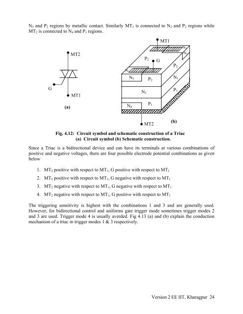
N 3 and P 2 regions by metallic contact. Similarly MT 1 is connected to N 2 and P 2 regions while<br />
MT 2 is connected to N 4 and P 1 regions.<br />
MT1<br />
G<br />
(a)<br />
MT2<br />
MT1<br />
N 2<br />
N 2<br />
P 2 G<br />
P 2<br />
N 3<br />
N 3 P N 1<br />
2<br />
N<br />
P 1<br />
1<br />
N<br />
P 1 4<br />
MT2<br />
(b)<br />
Fig. 4.12: Circuit symbol and schematic construction of a <strong>Triac</strong><br />
(a) Circuit symbol (b) Schematic construction.<br />
Since a <strong>Triac</strong> is a bidirectional device and can have its terminals at various combinations of<br />
positive and negative voltages, there are four possible electrode potential combinations as given<br />
below<br />
1. MT 2 positive with respect to MT 1 , G positive with respect to MT 1<br />
2. MT 2 positive with respect to MT 1 , G negative with respect to MT 1<br />
3. MT 2 negative with respect to MT 1 , G negative with respect to MT 1<br />
4. MT 2 negative with respect to MT 1 , G positive with respect to MT 1<br />
The triggering sensitivity is highest with the combinations 1 and 3 and are generally used.<br />
However, for bidirectional control and uniforms gate trigger mode sometimes trigger modes 2<br />
and 3 are used. Trigger mode 4 is usually averded. Fig 4.13 (a) and (b) explain the conduction<br />
mechanism of a triac in trigger modes 1 & 3 respectively.<br />
Version 2 EE IIT, Kharagpur 24


