NTC Thermistors - Selco Products Company
NTC Thermistors - Selco Products Company
NTC Thermistors - Selco Products Company

Create successful ePaper yourself
Turn your PDF publications into a flip-book with our unique Google optimized e-Paper software.
FOODSERVICE HVAC INSTRUMENTATION LIFE SCINECES POWER SUPPLIES
Table of Contents<br />
Custom <strong>NTC</strong> Thermistor Probes - CP Series 4-7<br />
Custom Epoxy <strong>NTC</strong> <strong>Thermistors</strong> - CS Series 8-9<br />
Tiny <strong>NTC</strong> Thermsitor Probes - LS Series 10<br />
Miniature <strong>NTC</strong> Thermistor Probes - LSMN Mini Series 11<br />
Micro <strong>NTC</strong> Thermistor Probes - LSMC Micro Series 12<br />
Interchangeable <strong>NTC</strong> <strong>Thermistors</strong> - IN Series 13-14<br />
Diode Type <strong>NTC</strong> <strong>Thermistors</strong> - DT Series 15<br />
Thin Film <strong>NTC</strong> <strong>Thermistors</strong> - TF Series 16<br />
Short Lead <strong>NTC</strong> Epoxy <strong>Thermistors</strong> - HP Series 17<br />
Long Lead <strong>NTC</strong> Epoxy <strong>Thermistors</strong> - HT Series 18<br />
Point Matched <strong>NTC</strong> <strong>Thermistors</strong> - PM Series 19-20<br />
Insulated Lead Epoxy <strong>Thermistors</strong> - TS Series 21<br />
Standard SMT <strong>NTC</strong> <strong>Thermistors</strong> - SM Series 22<br />
Special SMT <strong>NTC</strong> <strong>Thermistors</strong> - CT Series 23<br />
Packaged <strong>NTC</strong> Probe <strong>Thermistors</strong> - TR Series 24<br />
Technical Notes 25<br />
Thermistor Definition<br />
Manufacturing Process<br />
Resistance - Temperature (R/T) Curves and <strong>NTC</strong><br />
Thermal Time Constant<br />
Dissipation Constant<br />
Voltage/Current Requirements<br />
Beta<br />
Steinhart-Hart Equation<br />
Temperature Rating<br />
Stability<br />
Resistance - Temperature Tables 26-27<br />
Application Notes 28-30<br />
(775) 674-5100 (800) 257-3526 FAX (775) 674-5111 E-mail: sales@selcoproducts.com<br />
www.selcoproducts.com<br />
3
Custom <strong>NTC</strong> Thermistor Probes<br />
CP Series<br />
Temperature Sensor Applications<br />
Household Appliances Medical Electronics Industrial Electronics<br />
Dryers Infant Incubators Fire Detectors<br />
Heaters Blood Analysis Equipment Solar Collector<br />
Toasters Skin Temperature Monitors HVAC Equipment<br />
Refrigerators Internal Temperature Sensor Water Purification<br />
Coffee Makers Respiration Rate Measurement Plastic Laminating<br />
Air Conditioners Electronic Clinical Thermometer Vending Machines<br />
Washing Machines Welding Equipment<br />
Weather Monitoring<br />
Other Consumer Electronics Automotive Industrial Process Control<br />
Cooling Fan Hybrid Battery Sensor Oceanography Monitoring<br />
Battery Pack Water / Oil Tank Sensor Fruit Transportation Process Control<br />
Wireless Card Automatic Climate Control<br />
Audio Amplifiers Outside Air Temperature Sensor<br />
Cellular Telephones Engine Block Temperature Sensor<br />
Pool and Spa Control<br />
(775) 674-5100 (800) 257-3526 FAX (775) 674-5111 E-mail: sales@selcoproducts.com<br />
4<br />
www.selcoproducts.com
Custom <strong>NTC</strong> Thermistor Probes<br />
CP Series<br />
FEATURES<br />
RoHS Compliant<br />
Virtually unlimited options<br />
Customer specification or made from stock materials<br />
Available in Interchangeable or Point Matched tolerances<br />
CP Series probes are designed to meet your specific<br />
application requirements. Custom probe designs have<br />
virtually unlimited options available. Their value-added<br />
features significantly reduce your labor costs.<br />
Contact our applications engineering personnel for<br />
assistance in designing a probe from the standard<br />
components listed on the following pages or from a<br />
multitude of other materials.<br />
SPECIFICATIONS<br />
Temperature rating/<br />
recommened operating<br />
ranges<br />
CP Series probes may be intermittently<br />
cycled at temperatures from -50ºC to<br />
150ºC. Optimum stability is achieved<br />
when they are stored at temperature<br />
less than 50ºC and operated continously<br />
at temperatures less than 100ºC.<br />
Note: CP Series probes using the DT Series glass thermistor may<br />
be intermittently cycled from -50ºC to 250ºC. Optimum stability<br />
is achieved when they are stored at less than 50ºC and operated<br />
continuously at temperatures less than 220ºC.<br />
For CP Series probes using interchangeable thermistor elements,<br />
optimum stability is achieved when they are operated at temperatures<br />
within the specified temperature range.<br />
R/T curves<br />
Tolerances<br />
CP Series thermistors probes are<br />
available in all R/T curve materials.<br />
Detailed curve material information on<br />
pages 26-27.<br />
±0.10°C, ±0.20°C, ±0.25°C, ±0.50°C,<br />
±1.00°C, ±1%, ±2%, ±5%, ±10%<br />
Note: <strong>Selco</strong> can provide options such as corrosion resistant housings,<br />
high pressure (PSI) housings, custom plastic molded or over-molded<br />
thermistor sub assemblies, and moisture resistant thermistor probe<br />
assemblies. Contact <strong>Selco</strong> applications engineering for information.<br />
The following are a few examples of the unlimited choices for the combination of wire and probe housings<br />
Wire Styles Configuration Gauge Insulation<br />
Single Conductor<br />
18-32<br />
PVC, XLPE Teflon<br />
Zipcord<br />
22-30<br />
PVC<br />
Jacketed<br />
22-26<br />
PVC, Teflon<br />
Twisted<br />
22-24<br />
PVC, Etched Teflon<br />
(775) 674-5100 (800) 257-3526 FAX (775) 674-5111 E-mail: sales@selcoproducts.com<br />
www.selcoproducts.com<br />
5
Custom <strong>NTC</strong> Thermistor Probes<br />
CP Series<br />
The following are a few examples of the unlimited choices for the combination of wire and probe housings<br />
Housings Type Material<br />
Threaded NPT<br />
fitting round,<br />
close-end tube<br />
Brass<br />
316 Stainless Steel<br />
Flat closed-ended<br />
PVC, Stainless Steel,<br />
Brass, Overmold<br />
Rounded, closed-end cup<br />
Delrin, Stainless Steel,<br />
Brass, Overmold<br />
Ring lug terminal bolt<br />
Steel, Copper<br />
Ring lug terminal bolt<br />
Steel, Copper<br />
’<br />
Probe<br />
304 Stainless Steel,<br />
316 Stainless Steel,<br />
Brass, Aluminum, Plastic<br />
Threaded NPT plug<br />
304 Stainless Steel,<br />
316 Stainless Steel,<br />
Brass, Aluminum,<br />
Plastic, Overmold<br />
Open-end tube<br />
304 Stainless Steel,<br />
316 Stainless Steel,<br />
Brass, Aluminum, Plastic<br />
Expanded Probe<br />
304 Stainless Steel,<br />
316 Stainless Steel,<br />
Brass, Aluminum, Plastic<br />
Tapered-end Probe<br />
304 Stainless Steel,<br />
316 Stainless Steel,<br />
Brass, Aluminum, Plastic<br />
Flange Mount Probe<br />
304 Stainless Steel,<br />
316 Stainless Steel,<br />
Brass, Aluminum, Plastic<br />
(775) 674-5100 (800) 257-3526 FAX (775) 674-5111 E-mail: sales@selcoproducts.com<br />
6<br />
www.selcoproducts.com
Custom <strong>NTC</strong> Thermistor Probes<br />
CP Series - Ordering Map<br />
ORDERING MAP<br />
CP - - - X X X X<br />
R/T Curve<br />
A = Curve A E = Curve E H = Curve H<br />
B = Curve B F = Curve F K = Curve K<br />
C = Curve C G = Curve G P = Curve P<br />
D = Curve D X = New letter assisgned for special curve<br />
Resistance in Ohms at 25°C<br />
0300 = 300 Ohms<br />
001K = 1K Ohms<br />
005K = 5K Ohms<br />
006K = 6K Ohms<br />
010K = 10K Ohms<br />
100K = 100K Ohms<br />
2252 = 2,252 Ohms<br />
1MEG = 1 Million Ohms<br />
X = Special base resistance value<br />
IN Type Only Tolerance at 25°C<br />
A = ±1.0°C<br />
C = ±0.2°C<br />
B = ±0.5°C<br />
D = ±0.1°C<br />
X = new letter assigned on special<br />
PM Type Only Tolerance at 25°C<br />
1 = ±1% 5 = ±5%<br />
2 = ±2% 0 = ±10%<br />
3 = ±3% X = letter or digit assigned for specials<br />
IN Type Only Temperature Ranges<br />
1 = 20°C to 45°C 6 = -40°C to 40°C<br />
2 = -20°C to 50°C 7 = +50°C to 125°C<br />
3 = 0°C to 70°C 8 = 0°C to 50°C<br />
4 = 0°C to 100°C 9 = -20°C to 125°C<br />
5 = +20°C to 90°C X = new digit assigned for specials<br />
PM Type Only Temperature Ranges<br />
A = -20°C D = 37°C<br />
B = 0°C E = 70°C<br />
C = 25°C F = 100°C<br />
X = digit to be assigned for specials<br />
XXXX = System file number assigned<br />
Note: Other thermistor base resistance values, thermistor curves or Beta values, or tolerances may be available.<br />
Please contact <strong>Selco</strong> <strong>Products</strong>.<br />
TO ORDER SPECIFY ALL ITEMS BELOW<br />
<br />
<br />
<br />
<br />
<br />
<br />
<br />
Lead length<br />
Wire gauge size<br />
Solid or stranded wire<br />
Probe type description<br />
Connectors if required (Molex, Amp or other)<br />
Blunt or stripped end and length of stripped wire<br />
Insulation material (Isomid, Kynar, Nylon, PVC, Teflon, etc.)<br />
(775) 674-5100 (800) 257-3526 FAX (775) 674-5111 E-mail: sales@selcoproducts.com<br />
www.selcoproducts.com<br />
7
Custom Epoxy <strong>NTC</strong> <strong>Thermistors</strong><br />
CS Series<br />
FEATURES<br />
RoHS Compliant<br />
Customer specified<br />
Various material options<br />
Modified stock or new custom design<br />
Available in Interchangeable or Point Matched tolerances<br />
CS Series thermistors are designed to meet your specific application requirements. For “turn-key” solutions, their value-added<br />
features can significantly reduce your labor costs. Contact our applications engineering personnel for assistance in designing a<br />
standard thermistor into a custom thermistor to match your needs.<br />
SPECIFICATIONS<br />
Temperature rating/<br />
recommended operating<br />
ranges<br />
R/T curves<br />
Tolerances<br />
CS Series thermistors may be<br />
intermittently cycled at temperatures<br />
from -50°C to 150°C. Optimum stability<br />
is achieved when they are stored at<br />
temperatures less than 50°C and will<br />
operate continuously in temperatures less<br />
than 100°C. For CS Interchangeable<br />
Series thermistors, optimum stability is<br />
achieved when they are operated at<br />
temperatures within the specified<br />
temperature range.<br />
CS Series thermistors are available in<br />
all R/T curve materials. Detailed curve<br />
material information on pages 26-27.<br />
±0.10°C<br />
±0.20°C<br />
±0.25°C<br />
±0.50°C<br />
±1.00°C<br />
±1%<br />
±2%<br />
±3%<br />
±5%<br />
±10%<br />
Dissipation constant<br />
Thermal time constant<br />
Maximum power rating<br />
Custom options<br />
1m W/°C in still air<br />
8m W/°C in stirred oil<br />
Time constant varies depending on the<br />
configuration of each custom thermistor.<br />
Typically 1 second in stirred oil.<br />
30 mW at 25°C to 1mW at 100°C (used<br />
in ‘self-heat’ applications such as liquid<br />
level control and air flow sensing).<br />
Various lead diameters, insulation<br />
materials, lead lengths and connectors<br />
Note: Several CS Series <strong>Thermistors</strong> are available with UL Component Recognition. Please contact <strong>Selco</strong> <strong>Products</strong> for availability.<br />
(775) 674-5100 (800) 257-3526 FAX (775) 674-5111 E-mail: sales@selcoproducts.com<br />
8<br />
www.selcoproducts.com
Custom Epoxy <strong>NTC</strong> <strong>Thermistors</strong><br />
CS Series - Ordering Map<br />
ORDERING MAP<br />
CS - - - X X X X<br />
R/T Curve<br />
A = Curve A E = Curve E H = Curve H<br />
B = Curve B F = Curve F K = Curve K<br />
C = Curve C G = Curve G P = Curve P<br />
D = Curve D X = New letter assisgned for special curve<br />
Resistance in Ohms at 25°C<br />
0300 = 300 Ohms<br />
001K = 1K Ohms<br />
005K = 5K Ohms<br />
006K = 6K Ohms<br />
010K = 10K Ohms<br />
100K = 100K Ohms<br />
2252 = 2,252 Ohms<br />
1MEG = 1 Million Ohms<br />
X = Special base resistance value<br />
IN Type Only Tolerance at 25°C<br />
A = ±1.0°C<br />
C = ±0.2°C<br />
B = ±0.5°C<br />
D = ±0.1°C<br />
X = new letter Y = ±0.25°C<br />
assigned for specials<br />
PM Type Only Tolerance at 25°C<br />
1 = 1% 0 = 10%<br />
2 = 2% A = 0.25°C<br />
3 = 3% B = 0.50°C<br />
5 = 5% X = letter or digit to be assigned for specials<br />
IN Type Only Temperature Ranges<br />
1 = +20°C to 45°C 6 = -40°C to 40°C<br />
2 = -20°C to 50°C 7 = +50°C to 125°C<br />
3 = 0°C to 70°C 8 = 0°C to 50°C<br />
4 = 0°C to 100°C 9 = -20°C to 125°C<br />
5 = +20°C to 90°C X = new digit assigned for specials<br />
PM Type Only Temperature Ranges<br />
A = -20°C D = 37°C<br />
B = 0°C E = 70°C<br />
C = 25°C F = 100°C<br />
X = digit to be assigned for specials<br />
XXXX = System file number assigned<br />
Note: Other thermistor base resistance values, thermistor curves or Beta values, or tolerances may be available.<br />
Please contact <strong>Selco</strong> <strong>Products</strong>.<br />
TO ORDER SPECIFY ALL ITEMS BELOW<br />
<br />
<br />
<br />
<br />
<br />
<br />
Lead wire length<br />
Wire gauge size<br />
Solid or stranded wire<br />
Connectors if required (Molex, Amp or other)<br />
Blunt or stripped end and length of stripped wire<br />
Insulation material (Isomid, Kynar, Nylon, PVC, Teflon, etc.)<br />
(775) 674-5100 (800) 257-3526 FAX (775) 674-5111 E-mail: sales@selcoproducts.com<br />
www.selcoproducts.com<br />
9
Tiny <strong>NTC</strong> Thermistor Probes<br />
LS Series .078” (1.98) diameter<br />
LS400 Series - 2252 Ohms at 25°C “A” Curve<br />
LS700 Series - “A” or “B” Curve<br />
Other values and curves available. Detailed values and curve information<br />
on pages 26-27.<br />
FEATURES<br />
RoHS Compliant<br />
Interchangeable tolerance<br />
Skin and catheter disposable sensor designs<br />
These thermistors offer a precision method of life science and patient<br />
care temperature sensing. Our disposable sensors meet the necessity<br />
of low cost without comprising high quality and precise accuracy.<br />
SPECIFICATIONS<br />
Temperature rating/<br />
recommended operating<br />
ranges<br />
R/T curves<br />
LS Series thermistors may be<br />
intermittently cycled at temperatures<br />
from -50°C to 150°C. Optimum stability<br />
is achieved when thermistors are<br />
operated at temperatures within the<br />
specified temperature range.<br />
LS Series is manufactured with “A” or<br />
“B” R/T curve materials. Detailed curve<br />
material information on pages 26-27.<br />
Tolerances<br />
Dissipation constant<br />
Thermal time constant<br />
Custom options<br />
±0.10°C<br />
±0.20°C<br />
±0.50°C<br />
±1.00°C<br />
2.5 mW/°C in still air<br />
13 mW/°C in stirred oil<br />
Typically 1.25 seconds in stirred oil<br />
Various lead materials, terminations<br />
and lengths<br />
ORDERING MAPS<br />
LS 400 A<br />
Wire<br />
Gauge<br />
#28AWG<br />
R/T Curve<br />
A = A Curve<br />
Resistance in<br />
Ohms @ 25°C<br />
2252 = 2,252 Ohms<br />
Tolerances<br />
@ 25°C<br />
A = ±1.0°C<br />
B = ±0.5°C<br />
C = ±0.2°C<br />
D = ±0.1°C<br />
Lead Length<br />
Lead Length Example<br />
04 = 4.0”<br />
Special Options<br />
LS 700<br />
Wire<br />
Gauge<br />
#30AWG<br />
R/T Curve<br />
A = A Curve<br />
B = B Curve<br />
Resistance in<br />
Ohms @ 25°C<br />
006K = 6,000 Ohms<br />
030K = 30,000 Ohms<br />
100K = 100,000 Ohms<br />
Tolerances<br />
@ 25°C<br />
A = ±1.0°C<br />
B = ±0.5°C<br />
C = ±0.2°C<br />
D = ±0.1°C<br />
Lead Length<br />
Lead Length Example<br />
10 = 10.0”<br />
Special Options<br />
Contact <strong>Selco</strong> <strong>Products</strong> for your special requirements.<br />
(775) 674-5100 (800) 257-3526 FAX (775) 674-5111 E-mail: sales@selcoproducts.com<br />
10<br />
www.selcoproducts.com
Miniature <strong>NTC</strong> Thermistor Probes<br />
LSMN Mini Series 0.035” and 0.055” maximum diameter<br />
LSMN 400 or 700 Series<br />
400: 2252 Ohms at 25°C “A” Curve<br />
700: “A” or “B” Curves<br />
LSMN 400 Series<br />
2252 Ohms at 25°C “A” Curve<br />
FEATURES<br />
RoHS Compliant<br />
Fast response accuracy to ±0.1°C<br />
Interchangeable or Point Matched tolerances<br />
Other values and curves available. Detailed values and curve information on<br />
pages 26-27.<br />
These tiny thermistors can be used in applications that require fast response and small size. Since they are available with<br />
custom options they can be used in unlimited temperature sensing applications in any industry.<br />
SPECIFICATIONS<br />
Temperature rating/<br />
recommended operating<br />
ranges<br />
LSMN Series thermistors may be<br />
intermittently cycled at temperatures<br />
from -50°C to 150°C. Optimum stability<br />
is achieved when thermistors are<br />
stored at temperatures less than 100°C.<br />
For interchangeable LSMN Mini Series<br />
thermistors optimum stability is achieved<br />
when they are operated at temperatures<br />
within the specified temperature range.<br />
Note: Probe housing lengths available from .125” to .375” (3.18 - 9.53)<br />
R/T curves<br />
Tolerances<br />
Dissipation constant<br />
Thermal time constant<br />
Custom options<br />
LSMN Mini Series is manufactured with<br />
‘A’ or ‘B’ R/T curve materials. Detailed<br />
curve material information on pages 26-27.<br />
±0.10°C, ±0.20°C, ±0.25°C, ±0.50°C,<br />
±1.00°C, ±1%, ±2% , ±3%, ±5%, ±10%<br />
1.5 mW/°C in still air<br />
10 mW/°C in stirred oil<br />
Typically 0.4 seconds in stirred oil<br />
Various lead materials and lengths<br />
LSMN400A<br />
ORDERING MAPS<br />
R/T Curve<br />
A = A Curve<br />
Resistance in<br />
Ohms @ 25°C<br />
2252 = 2,252 Ohms<br />
Tolerances @ 25°C<br />
A = ±1.0°C 1 = ±1%<br />
B = ±0.5°C 2 = ±2%<br />
C = ±0.2°C 3 = ±3%<br />
D = ±0.1°C 4 = ±4%<br />
X = SPECIAL 5 = ±5%<br />
Wire Gauge and<br />
Probe Diameter<br />
2 = #28AWG, 0.055” Probe Diameter<br />
3 = #32AWG, 0.035” Probe Diameter<br />
Lead Length or<br />
Special Options<br />
LSMN700<br />
R/T Curve<br />
A = A Curve<br />
B = B Curve<br />
Resistance in<br />
Ohms @ 25°C<br />
006K = 6,000 Ohms<br />
010K = 10,000 Ohms<br />
030K = 30,000 Ohms<br />
Tolerances @ 25°C<br />
A = ±1.0°C 1 = ±1%<br />
B = ±0.5°C 2 = ±2%<br />
C = ±0.2°C 3 = ±3%<br />
D = ±0.1°C 4 = ±4%<br />
X = SPECIAL 5 = ±5%<br />
Wire Gauge and<br />
Probe Maximum Diameter<br />
2 = #28AWG, 0.055” Probe Diameter<br />
3 = #32AWG, 0.035” Probe Diameter<br />
Lead Length or<br />
Special Options<br />
Contact <strong>Selco</strong> <strong>Products</strong> for your special requirements.<br />
(775) 674-5100 (800) 257-3526 FAX (775) 674-5111 E-mail: sales@selcoproducts.com<br />
www.selcoproducts.com<br />
11
Micro <strong>NTC</strong> Thermistor Probes<br />
LSMC Micro Series 0.0185” and 0.0190” max. dia. capability to 0.175” dia.<br />
LSMC 700 Series<br />
10K Ohms, 30K Ohms, or 100K Ohms at 25°C “A” Curve<br />
LSMC 400 Series<br />
2252 Ohms at 25°C “A” Curve<br />
Other values and curves available. Detailed values and curve information on<br />
pages 26-27.<br />
FEATURES<br />
RoHS Compliant<br />
Fast response accuracy to ±0.1°C<br />
Interchangeable or Point Matched tolerances<br />
These tiny thermistors can be used in many Life Science applications. They<br />
are small enough to fit into a hypodermic needle. Since they are available<br />
in many custom options they can be used for fast response temperature<br />
sensing applications in any industry.<br />
SPECIFICATIONS<br />
Temperature rating/<br />
recommended operating<br />
ranges<br />
LSMC Series thermistors may be<br />
intermittently cycled at temperatures<br />
from -50°C to 150°C. Optimum stability<br />
is achieved when thermistors are<br />
stored at temperatures less than 50°C.<br />
and operated continuously in<br />
temperatures less than 100°C. For<br />
interchangeable LSMC Series thermistors<br />
optimum stability is achieved when they<br />
are operated at temperatures within the<br />
specified temperature range.<br />
R/T curve<br />
Tolerances<br />
Dissipation constant<br />
Thermal time constant<br />
Lead materials<br />
LSMC Series is manufactured with<br />
‘A’ R/T curve material. Detailed curve<br />
material information on pages 26-27.<br />
±0.10°C, ±0.20°C, ±0.25°C, ±0.50°C<br />
±1.00°C, ±1%, ±2%, ±5%, ±10%<br />
0.3 mW/°C in still air<br />
2.5 mW/°C in stirred oil<br />
Typically 0.4 seconds in stirred oil<br />
AWG 38 nickel alloy or copper<br />
conductors with heavy isomid insulation,<br />
parallel bonded configuration.<br />
LSMC400A<br />
ORDERING MAP<br />
R/T Curve<br />
A = A Curve<br />
Resistance in<br />
Ohms @ 25°C<br />
2252 = 2,252 Ohms<br />
Tolerances @ 25°C<br />
A = ±1.0°C 1 = ±1%<br />
B = ±0.5°C 2 = ±2%<br />
C = ±0.2°C 3 = ±5%<br />
D = ±0.1°C 4 = ±10%<br />
X = SPECIAL<br />
Lead Length or<br />
Special Options<br />
LSMC700A<br />
R/T Curve<br />
A = A Curve<br />
Resistance in<br />
Ohms @ 25°C<br />
010K = 10,000 Ohms<br />
030K = 30,000 Ohms<br />
100K = 100,000 Ohms<br />
Tolerances @ 25°C<br />
A = ±1.0°C 1 = ±1%<br />
B = ±0.5°C 2 = ±2%<br />
C = ±0.2°C 3 = ±5%<br />
D = ±0.1°C 4 = ±10%<br />
X = SPECIAL<br />
Lead Length or<br />
Special Options<br />
Contact <strong>Selco</strong> <strong>Products</strong> for your special requirements.<br />
(775) 674-5100 (800) 257-3526 FAX (775) 674-5111 E-mail: sales@selcoproducts.com<br />
12<br />
www.selcoproducts.com
Interchangeable <strong>NTC</strong> <strong>Thermistors</strong><br />
IN Series<br />
FEATURES<br />
RoHS Compliant<br />
Small size with ease of handling<br />
High accuracy tolerance to ±0.10°C<br />
Operating ranges from -50°C to 150°C<br />
Proprietary processes produce top of the line quality and<br />
stability<br />
SPECIFICATIONS<br />
Interchangeable refers to how accurately thermistors follow<br />
the R/T curve over a range of temperatures. This allows<br />
every thermistor of the same series specifications to be<br />
exchangeable.<br />
Temperature rating/<br />
recommended operating<br />
ranges<br />
Temperature ranges -20°C to 50°C<br />
0°C to 50°C<br />
20°C to 45°C<br />
0°C to 70°C<br />
0°C to 100°C<br />
Tolerances<br />
IN Series thermistors may be<br />
intermittently cycled at temperatures<br />
from -50°C to 150°C. Optimum stability<br />
is achieved when they are operated at<br />
temperatures within the specified<br />
temperature range.<br />
±0.10°C<br />
±0.20°C<br />
±0.50°C<br />
±1.00°C<br />
R/T curves<br />
IN Series thermistors are available in<br />
all R/T curve materials. Detailed curve<br />
material information on pages 26-27.<br />
Dissipation constant 2m W/°C in still air<br />
13m W/°C in stirred oil<br />
Thermal time constant Typically 0.75 seconds in stirred oil<br />
Maximum power rating 30 mW at 25°C to 1mW at 100°C<br />
(775) 674-5100 (800) 257-3526 FAX (775) 674-5111 E-mail: sales@selcoproducts.com<br />
www.selcoproducts.com<br />
13
Interchangeable <strong>NTC</strong> <strong>Thermistors</strong><br />
IN Series - Order Map<br />
ORDERING MAP<br />
IN- - - XX<br />
R/T Curve<br />
A = Curve A E = Curve E H = Curve H<br />
B = Curve B F = Curve F K = Curve K<br />
C = Curve C G = Curve G P = Curve P<br />
D = Curve D X = New letter assisgned for special curve<br />
Resistance in Ohms at 25°C<br />
001K = 1K Ohms<br />
003K = 3K Ohms<br />
006K = 6K Ohms<br />
010K = 10K Ohms<br />
020K = 20K Ohms<br />
030K = 30K Ohms<br />
100K = 100K Ohms<br />
2252 = 2,252 Ohms<br />
X = special base resistance value<br />
Tolerance at 25°C<br />
A = ±1.0°C<br />
B = ±0.5°C<br />
C = ±0.2°C<br />
D = ±0.1°C<br />
X = new letter Y = ±0.25°C<br />
assigned for specials<br />
Temperature Ranges<br />
1 = +20°C to 45°C 6 = -40°C to 40°C<br />
2 = -20°C to 50°C 7 = +50°C to 125°C<br />
3 = 0°C to 70°C 8 = 0°C to 50°C<br />
4 = 0°C to 100°C 9 = -20°C to 125°<br />
5 = +20°C to 90°C X = new digit assigned for specials<br />
2” Leads<br />
3” Leads<br />
Code AWG Lead O.D. Lead Type Chip Coating Code AWG Lead O.D. Lead Type Chip Coating<br />
04<br />
05<br />
06<br />
07<br />
08<br />
09<br />
10<br />
11<br />
12<br />
13<br />
14<br />
16<br />
18<br />
20<br />
30<br />
26<br />
28<br />
32<br />
30<br />
26<br />
26<br />
32<br />
32<br />
30<br />
30<br />
28<br />
32<br />
28<br />
0.010”<br />
0.0169”<br />
0.0126”<br />
0.008”<br />
0.010”<br />
0.0159”<br />
0.0159”<br />
0.008”<br />
0.008”<br />
0.010”<br />
0.010”<br />
0.0126”<br />
0.008”<br />
0.0126”<br />
Tinned Alloy<br />
Tinned Copper<br />
Tinned Copper<br />
Tinned Copper<br />
Nickel<br />
Tinned Alloy 180<br />
Tinned Copper<br />
Nickel<br />
Tinned Copper<br />
Tinned Alloy 180<br />
Tinned Copper<br />
Tinned Copper<br />
Tinned Alloy 180<br />
Nickel<br />
Uncoated<br />
Epoxy<br />
Epoxy<br />
Epoxy<br />
Epoxy<br />
Epoxy<br />
Epoxy<br />
Epoxy<br />
Epoxy<br />
Epoxy<br />
Epoxy<br />
Epoxy<br />
Epoxy<br />
Epoxy<br />
21<br />
22<br />
24<br />
26<br />
28<br />
31<br />
41*<br />
32<br />
32<br />
30<br />
28<br />
32<br />
30<br />
30<br />
* 6K to 30K only<br />
0.008”<br />
0.008”<br />
0.010”<br />
0.0126”<br />
0.008”<br />
0.010”<br />
0.010”<br />
Nickel<br />
Tinned Copper<br />
Tinned Copper<br />
Tinned Copper<br />
Tinned Alloy 180<br />
Teflon<br />
Ag/Cu Twisted Kynar<br />
Epoxy<br />
Epoxy<br />
Epoxy<br />
Epoxy<br />
Epoxy<br />
Epoxy<br />
Epoxy<br />
For optional lengths other than 2” or 3” substitute XX with<br />
lengths in inches<br />
Example: 04 = 4.0”<br />
Note: Other thermistor base resistance values, thermistor curves or Beta values, or tolerances may be available.<br />
Please contact <strong>Selco</strong> <strong>Products</strong>.<br />
Custom designs are available, please fax or e-mail us your requirements<br />
(775) 674-5100 (800) 257-3526 FAX (775) 674-5111 E-mail: sales@selcoproducts.com<br />
14<br />
www.selcoproducts.com
Diode Type <strong>NTC</strong> <strong>Thermistors</strong><br />
DT Series<br />
FEATURES<br />
RoHS Compliant Glass sealed body for high reliability<br />
High stability and low cost Excellent thermal cycle endurance<br />
Leads may be precut and custom<br />
formed to your specification<br />
The DT thermistor is a thermal sensor in a DO35 package. The highly reliable thermistor is offered in a wide temperature range<br />
of -50°C to 250°C. It can be used in a variety of applications including high temperature applications.<br />
SPECIFICATIONS<br />
Temperature range -50°C to 250°C<br />
R25<br />
Rated Zero-power<br />
Resistance value at 25°C<br />
10,000 Ohms<br />
15,000 Ohms<br />
30,000 Ohms<br />
47,000 Ohms<br />
50,000 Ohms<br />
100,000 Ohms<br />
200,000 Ohms<br />
500,000 Ohms<br />
Tolerances ±1%, ±3%, ±5%<br />
B value<br />
A Curve = 3977K<br />
C Curve = 3695K<br />
D Curve = 4262K<br />
F Curve = 3435K<br />
Determined by rated zero-power resistance at 25°C and 85°C<br />
Dissipation constant Minimum 2.4 mW/°C<br />
Thermal time constant Typically 3.0 seconds in still air<br />
Typically 1.0 seconds in oil bath<br />
Maximum power rating 250 mW at 25°C<br />
ORDERING MAP<br />
DT - -<br />
R/T CURVE<br />
A = Curve A<br />
C = Curve C<br />
D = Curve D<br />
F = Curve F<br />
X = New letter assigned for<br />
special curve<br />
Resistance in Ohms @ 25°C<br />
010K = 10K Ohms<br />
015K = 15K Ohms<br />
030K = 30K Ohms<br />
047K = 47K Ohms<br />
050K = 50K Ohms<br />
100K = 100K Ohms<br />
200K = 200K Ohms<br />
500K = 500K Ohms<br />
X = Special base resistance value<br />
Tolerances<br />
1 = ±1%<br />
3 = ±3%<br />
5 = ±5%<br />
Optional Special<br />
Specification<br />
Note: Some products within the DT Series are available with UL component recognition. Please contact <strong>Selco</strong> <strong>Products</strong> or visit our website for availability.<br />
Note: Other thermistor base resistance values, thermistor curves or Beta values, or tolerances may be available.<br />
Please contact <strong>Selco</strong> <strong>Products</strong>.<br />
(775) 674-5100 (800) 257-3526 FAX (775) 674-5111 E-mail: sales@selcoproducts.com<br />
www.selcoproducts.com<br />
15
Thin Film <strong>NTC</strong> <strong>Thermistors</strong><br />
TF Series<br />
FEATURES<br />
RoHS Compliant<br />
Rapid response time<br />
Suitable for narrow space<br />
Note:<br />
L: .59” (15mm)<br />
.98” (25mm)<br />
1.97” (50mm)<br />
2.95” (75mm)<br />
The TF thermistor features ultra thinness of 500 :m and superior electrical insulation. It may safely be used in surroundings<br />
that includes contacts with electrodes.<br />
SPECIFICATIONS<br />
Temperature range -50°C to 90°C<br />
R25: Rated Zero-power 10,000 Ohms<br />
Tolerances ±1%<br />
±3%<br />
±5%<br />
B value<br />
3977K, 3435K<br />
Determined by rated zero-power resistance at 25°C and 85°C<br />
R/T curves<br />
Dissipation constant<br />
Thermal time constant<br />
A Curve<br />
F Curve<br />
0.7 mW/°C in still air<br />
Maximum power rating 3.5 mW at 25°C<br />
RoHS Compliant<br />
Typically 2.0 seconds in air<br />
Typically 0.8 seconds in stirred oil bath<br />
ORDERING MAP<br />
TF - - 010K - -<br />
R/T Curve<br />
A = A Curve<br />
F = Curve F<br />
X = New letter assigned for<br />
special curve<br />
Resistance in Ohms at 25°C<br />
010K = 10K Ohms<br />
X = Special base resistance value<br />
Tolerances<br />
1 = ±1%<br />
3 = ±3%<br />
5 = ±5%<br />
Overall Length<br />
1 = .59” (15mm)<br />
2 = .98” (25mm)<br />
3 = 1.97” (50mm)<br />
4 = 2.95” (75mm)<br />
Optional Special<br />
Specification<br />
Note: Please contact <strong>Selco</strong> <strong>Products</strong> regarding TF Series product with UL Component Recognition.<br />
Note: Other thermistor base resistance values, thermistor curves or Beta values, or tolerances may be available.<br />
Please contact <strong>Selco</strong> <strong>Products</strong>.<br />
(775) 674-5100 (800) 257-3526 FAX (775) 674-5111 E-mail: sales@selcoproducts.com<br />
16<br />
www.selcoproducts.com
Short Lead <strong>NTC</strong> Epoxy <strong>Thermistors</strong><br />
HP Series<br />
.14” (3.5) Max.<br />
0.12” (3.0) Max.<br />
FEATURES<br />
RoHS Compliant<br />
High stability and low cost<br />
Excellent thermal cycle endurance<br />
Tiebar cut allows consistent, accurate placement<br />
0.67”±.06 (17±1.5)<br />
0.34”±1 (8.5±1)<br />
.16” (4.0) Max.<br />
.03” (0.7)<br />
Tiebar cut<br />
.02” ( 0.5)<br />
Tin-Plated<br />
Copper<br />
Blue color<br />
Epoxy resin<br />
.02” ( 0.5)<br />
Tin-Plated<br />
Copper Leads<br />
The HP thermistor is a high-performance thermal<br />
sensing device.<br />
0.10±<br />
0.25<br />
(2.54±<br />
0.25)<br />
SPECIFICATIONS<br />
Temperature range -50°C to 110°C<br />
R25: Rated Zero-power resistance<br />
value at 25°C<br />
1,000 Ohms<br />
2,000 Ohms<br />
5,000 Ohms<br />
10,000 Ohms<br />
20,000 Ohms<br />
47,000 Ohms<br />
100,000 Ohms<br />
Tolerances ±1%, ±3%, ±5%<br />
B value<br />
3435K - 4847K<br />
Determined by rated zero-power resistance at 25°C and 85°C<br />
R/T curves<br />
HP Series thermistors are available in<br />
all R/T curve materials. Detailed curve<br />
material information on pages 26-27.<br />
Dissipation constant 2 mW/°C<br />
Thermal time constant Typically 3.0 seconds in air<br />
Typically 1.0 seconds in oil bath<br />
Maximum power rating 10 - 15 mW at 25°C<br />
HP - - -<br />
ORDERING MAP<br />
R/T Curve<br />
A = Curve A F = Curve F<br />
B = Curve B G = Curve G<br />
C = Curve C H = Curve H<br />
D = Curve D K = Curve K<br />
E = Curve E P = Curve P<br />
X = New letter assigned for special curve<br />
Resistance in Ohms at 25°C<br />
001K = 1K Ohms<br />
002K = 2K Ohms<br />
005K = 5K Ohms<br />
010K = 10K Ohms<br />
020K = 20K Ohms<br />
047K = 47K Ohms<br />
100K = 100K Ohms<br />
X = Special base resistance value<br />
Tolerances<br />
1 = ±1%<br />
3 = ±3%<br />
5 = ±5%<br />
Optional Special<br />
Specification<br />
Note: Other thermistor base resistance values, thermistor curves or Beta values, or tolerances may be available.<br />
Please contact <strong>Selco</strong> <strong>Products</strong>.<br />
(775) 674-5100 (800) 257-3526 FAX (775) 674-5111 E-mail: sales@selcoproducts.com<br />
www.selcoproducts.com<br />
17
Long Lead <strong>NTC</strong> Epoxy <strong>Thermistors</strong><br />
HT Series<br />
.157” (4.0) Max.<br />
.138” (3.5) Max.<br />
FEATURES<br />
RoHS Compliant<br />
High stability and low cost<br />
Excellent thermal cycle endurance<br />
1.18”±.059” (30±1.5)<br />
.157” (4.0) Max.<br />
.019” ( 5)<br />
Tin-Plated<br />
Copper Leads<br />
0.1” (2.54)<br />
Black color<br />
Epoxy resin<br />
.019” ( 5)<br />
Tin-Plated<br />
Coppper Leads<br />
The HT thermistor is a high-performance thermal sensing device.<br />
SPECIFICATIONS<br />
Temperature range -50°C to 110°C<br />
R25: Rated zero-power resistance<br />
value at 25°C<br />
1,000 Ohms<br />
2,000 Ohms<br />
5,000 Ohms<br />
10,000 Ohms<br />
20,000 Ohms<br />
47,000 Ohms<br />
100,000 Ohms<br />
Tolerances ±1%, ±3%, ±5%<br />
B value<br />
3435K - 4847K<br />
Determined by rated zero-power resistance at 25°C and 85°C<br />
R/T curves<br />
HT Series thermistors are available in<br />
most of the R/T curve materials.<br />
Detailed curve material information on<br />
pages 26-27.<br />
Dissipation constant 2 mW/°C<br />
Thermal time constant Typically 3.0 seconds in air<br />
Typically 0.9 seconds in oil bath<br />
Maximum power rating 10 - 15 mW at 25°C<br />
ORDERING MAP<br />
HT - - -<br />
R/T Curve<br />
A = Curve A D = Curve D G = Curve G<br />
B = Curve B E = Curve E K = Curve K<br />
C = Curve C F = Curve F P = Curve P<br />
X = New letter assigned for special curve<br />
Resistance in Ohms at 25°C<br />
001K = 1K Ohms<br />
002K = 2K Ohms<br />
005K = 5K Ohms<br />
010K = 10K Ohms<br />
020K = 20K Ohms<br />
047K = 47K Ohms<br />
100K = 100K Ohms<br />
X = Special base resistance value<br />
Tolerances<br />
1 = ±1%<br />
3 = ±3%<br />
5 = ±5%<br />
Optional Special<br />
Specification<br />
Note: Other thermistor base resistance values, thermistor curves or Beta values, or tolerances may be available.<br />
Please contact <strong>Selco</strong> <strong>Products</strong>.<br />
(775) 674-5100 (800) 257-3526 FAX (775) 674-5111 E-mail: sales@selcoproducts.com<br />
18<br />
www.selcoproducts.com
Point Matched <strong>NTC</strong> <strong>Thermistors</strong><br />
PM Series<br />
FEATURES<br />
RoHS Compliant<br />
Percentage (%) or degree °C tolerance<br />
Reduced cost for high volume applications<br />
Tolerance resistance matched to specific temperature<br />
PM Series thermistors are precision tested at a chosen<br />
tolerance to a specific temperature. This cost effective<br />
thermistor provides an advantage to industries with high<br />
volume applications, such as in HVAC, automotive, and<br />
industrial markets.<br />
SPECIFICATIONS<br />
Temperature rating/<br />
recommended operating<br />
ranges<br />
R/T curves<br />
Temperature ranges<br />
PM Series thermistors may be<br />
intermittently cycled at temperatures<br />
from -50°C to 150°C. Optimum stability<br />
is achieved when they are stored at<br />
temperatures less than 50°C and<br />
operated continuously in temperatures<br />
less than 100°C.<br />
PM Series thermistors are available in<br />
all R/T curve materials. Detailed curve<br />
material information on pages 26-27.<br />
-20°C<br />
0°C<br />
25°C<br />
37°C<br />
70°C<br />
100°C<br />
Tolerances<br />
Dissipation constant<br />
Thermal time constant<br />
Maximum power rating<br />
±0.25°C<br />
±1.0°C<br />
±1%<br />
±2%<br />
±3%<br />
±5%<br />
2m W/°C in still air<br />
13m W/°C in stirred oil<br />
Typically 0.75 seconds in stirred oil<br />
30 mW at 25°C to 1mW at 100°C (used<br />
in ‘self-heat’ applications such as liquid<br />
level control and air flow sensing).<br />
(775) 674-5100 (800) 257-3526 FAX (775) 674-5111 E-mail: sales@selcoproducts.com<br />
www.selcoproducts.com<br />
19
Point Matched <strong>NTC</strong> <strong>Thermistors</strong><br />
PM Series - Order Map<br />
ORDERING MAP<br />
PM - - - XX<br />
R/T Curve<br />
A = Curve A E = Curve E H = Curve H<br />
B = Curve B F = Curve F K = Curve K<br />
C = Curve C G = Curve G P = Curve P<br />
D = Curve D X = New letter assisgned for special curve<br />
Resistance in Ohms at 25°C<br />
001K = 1K Ohms<br />
005K = 5K Ohms<br />
006K = 6K Ohms<br />
010K = 10K Ohms<br />
100K = 100K Ohms<br />
2252 = 2,252 Ohms<br />
1MEG = 1 Million Ohms<br />
X = Special base resistance value<br />
Tolerance at 25°C<br />
1 = ±1% 0 = ±10%<br />
2 = ±2% A = ±0.25°C<br />
3 = ±3% B = ±0.50°C<br />
5 = ±5% X = letter or digit to be assigned for specials<br />
Temperature Ranges<br />
A = -20°C D = 37°C<br />
B = 0°C E = 70°C<br />
C = 25°C F = 100°C<br />
x = digit to be assigned for specials<br />
2” Leads<br />
3” Leads<br />
Code AWG Lead O.D. Lead Type Chip Coating Code AWG Lead O.D. Lead Type Chip Coating<br />
04<br />
05<br />
06<br />
07<br />
08<br />
09<br />
10<br />
11<br />
12<br />
13<br />
14<br />
16<br />
18<br />
20<br />
30<br />
26<br />
28<br />
32<br />
30<br />
26<br />
26<br />
32<br />
32<br />
30<br />
30<br />
28<br />
32<br />
28<br />
0.010”<br />
0.0169”<br />
0.0126”<br />
0.008”<br />
0.010”<br />
0.0159”<br />
0.0159”<br />
0.008”<br />
0.008”<br />
0.010”<br />
0.010”<br />
0.0126”<br />
0.008”<br />
0.0126”<br />
Tinned Alloy<br />
Tinned Copper<br />
Tinned Copper<br />
Tinned Copper<br />
Nickel<br />
Tinned Alloy 180<br />
Tinned Copper<br />
Nickel<br />
Tinned Copper<br />
Tinned Alloy 180<br />
Tinned Copper<br />
Tinned Alloy<br />
Tinned Alloy<br />
Nickel<br />
Epoxy<br />
Epoxy<br />
Epoxy<br />
Epoxy<br />
Epoxy<br />
Epoxy<br />
Epoxy<br />
Epoxy<br />
Epoxy<br />
Epoxy<br />
Epoxy<br />
Epoxy<br />
Epoxy<br />
Epoxy<br />
21<br />
22<br />
24<br />
26<br />
28<br />
31<br />
41*<br />
32<br />
32<br />
30<br />
28<br />
32<br />
30<br />
30<br />
* 6K to 30K only<br />
0.008”<br />
0.008”<br />
0.010”<br />
0.0126”<br />
0.008”<br />
0.010”<br />
0.010”<br />
Nickel<br />
Tinned Copper<br />
Tinned Copper<br />
Tinned Copper<br />
Tinned Alloy 180<br />
Teflon<br />
Ag/Cu Twisted Kynar<br />
Epoxy<br />
Epoxy<br />
Epoxy<br />
Epoxy<br />
Epoxy<br />
Epoxy<br />
Epoxy<br />
For optional lengths other than 2” or 3” substitute XX with<br />
lengths in inches<br />
Example: 04 = 4.0”<br />
Note: Other thermistor base resistance values, thermistor curves or Beta values, or tolerances may be available.<br />
Please contact <strong>Selco</strong> <strong>Products</strong>.<br />
(775) 674-5100 (800) 257-3526 FAX (775) 674-5111 E-mail: sales@selcoproducts.com<br />
20<br />
www.selcoproducts.com
Insulated Lead Epoxy <strong>Thermistors</strong><br />
TS Series<br />
.063” (1.6) Max.<br />
Polyurethane Insulation<br />
.118”± .039” (3.0 ± 1.0)<br />
3.42”± .118” (87.0 ± 3.0)<br />
Epoxy Coating (Black)<br />
Copper Alloy Insulated wire - 32AWG<br />
.157” (4.0) Max.<br />
FEATURES<br />
Fast response<br />
RoHS Compliant<br />
Polyurethane insulated leads<br />
Excellent thermal cycle endurance<br />
The TS thermistor is smaller than the HP and IN thermistors.<br />
It’s rapid response time and high reliability make it suitable for<br />
use in medical equipment and thermometers.<br />
SPECIFICATIONS<br />
Temperature range -50°C to 110°C<br />
R25: Rated Zero-power resistance<br />
value at 25°C<br />
1,000 Ohms<br />
Resistance<br />
2,000 Ohms<br />
2,252 Ohms<br />
4,000 Ohms<br />
5,000 Ohms<br />
10,000 Ohms<br />
20,000 Ohms<br />
30,000 Ohms<br />
50,000 Ohms<br />
100,000 Ohms<br />
232,000 Ohms<br />
Tolerances ±1%, ±3%, ±5%<br />
B value<br />
3435K - 4262K<br />
Determined by rated zero-power resistance at 25°C and 85°C<br />
R/T curves<br />
TS Series thermistors are available in<br />
most of the R/T curve materials.<br />
Detailed curve material information on<br />
pages 26-27.<br />
Dissipation constant 0.7 mW/°C<br />
Thermal time constant Typically 1.0 seconds in air<br />
Typically 0.8 seconds in oil bath<br />
Maximum power rating 3.5 mW at 25°C<br />
ORDERING MAP<br />
TS- -<br />
R/T Curve<br />
A = Curve A<br />
B = Curve B<br />
C = Curve C<br />
D = Curve D<br />
F = Curve F<br />
K = Curve K<br />
I = Curve I<br />
X = New letter assigned for<br />
special curve<br />
Resistance in Ohms at 25°C<br />
001K = 1K Ohms<br />
002K = 2K Ohms<br />
2252 = 2252 Ohms<br />
004K = 4K Ohms<br />
005K = 5K Ohms<br />
010K = 10K Ohms<br />
020K = 20K Ohms<br />
030K = 30K Ohms<br />
050K = 50K Ohms<br />
100K = 100K Ohms<br />
232K = 232K Ohms<br />
X = Special base resistance value<br />
Curve<br />
Availability<br />
A, I<br />
A, I<br />
A<br />
A<br />
A, F, K<br />
A, B, C, F, K<br />
A<br />
A, B<br />
A<br />
A, B, D<br />
D<br />
Resistance<br />
Tolerance<br />
1 = ±1%<br />
3 = ±3%<br />
5 = ±5%<br />
Optional Special<br />
Specification<br />
Note: Other thermistor base resistance values, thermistor curves or Beta values, or tolerances may be available.<br />
Please contact <strong>Selco</strong> <strong>Products</strong>.<br />
(775) 674-5100 (800) 257-3526 FAX (775) 674-5111 E-mail: sales@selcoproducts.com<br />
www.selcoproducts.com<br />
21
Standard SMT <strong>NTC</strong> <strong>Thermistors</strong><br />
SM Series<br />
FEATURES<br />
RoHS Compliant<br />
Surface mount capability<br />
Ultra small size and low capacitance<br />
Uniformly sized for pick place assembly<br />
This highly reliable SM thermistor is characterized by a fast<br />
response time due to the surface mounting on a PCB. Our<br />
manufacturing techniques produce the highest quality<br />
surface mount thermistors available in today’s market.<br />
Type<br />
1206<br />
0805<br />
0603<br />
0402<br />
Dim.<br />
L<br />
(±0.2)<br />
.126<br />
(3.2)<br />
.0787<br />
(2.0)<br />
.063<br />
(1.6)<br />
.039<br />
(1.0)<br />
W<br />
(±0.2)<br />
.063<br />
(1.6)<br />
.0492<br />
(1.25)<br />
.0315<br />
(0.8)<br />
.0197<br />
(0.5)<br />
L1<br />
.0787<br />
(2.0)<br />
.0551<br />
(1.4)<br />
.0472<br />
(1.0)<br />
.0276<br />
(0.7)<br />
A<br />
(±0.2)<br />
.0236<br />
0.6<br />
.0118<br />
(0.2)<br />
.0118<br />
(0.2)<br />
.0079<br />
(0.2)<br />
H<br />
(±0.2)<br />
.0433<br />
(1.1)<br />
.0118<br />
(0.3)<br />
.0118<br />
(0.3)<br />
.0236<br />
(0.5)<br />
SPECIFICATIONS<br />
Temperature range -40°C to 125°C<br />
R25: Rated Zero-power 10,000 Ohms<br />
resistance value at 25°C Note: Other base resistance and<br />
R-T curves available upon request.<br />
Please contact <strong>Selco</strong> <strong>Products</strong>.<br />
Tolerances ±1%<br />
±3%<br />
±5%<br />
B25/85 value 10,000 Ohms - F Curve (3435K)<br />
Dissipation constant 3.5 mW/°C in still air<br />
Thermal time constant Typically 5-8 seconds in still air<br />
Maximum power rating 350-450 mW at 25°C<br />
Reel quantity<br />
1206 - 3K reel<br />
0805 - 4K reel<br />
0603 - 4K reel<br />
0402 - 10K reel<br />
ORDERING MAP<br />
SM - - F 0 1 0 K -<br />
Size Type<br />
1206<br />
0805<br />
0603<br />
0402<br />
Curve/Resistance in<br />
Ohms @ 25°C<br />
F010K = Curve F 10K Ohms<br />
Tolerances<br />
@ 25°C<br />
1 = ±1%<br />
3 = ±3%<br />
5 = ±5%<br />
Packaging<br />
T = Tape Reel<br />
B = Bulk<br />
Note: Other thermistor base resistance values, thermistor curves or Beta values, or tolerances may be available.<br />
Please contact <strong>Selco</strong> <strong>Products</strong>.<br />
(775) 674-5100 (800) 257-3526 FAX (775) 674-5111 E-mail: sales@selcoproducts.com<br />
22<br />
www.selcoproducts.com
Special SMT <strong>NTC</strong> <strong>Thermistors</strong><br />
CT Series<br />
FEATURES<br />
RoHS Compliant<br />
Surface mount capability<br />
Ultra small size and low capacitance<br />
Uniformly sized for pick place assembly<br />
The CT thermistor, a highly reliable thermistor, is characterized by a fast response and standard chip package sizes.<br />
Type<br />
1206<br />
0805<br />
0603<br />
Dim.<br />
L<br />
(±0.2)<br />
.126<br />
(3.2)<br />
.0787<br />
(2.0)<br />
.063<br />
(1.6)<br />
W<br />
(±0.2)<br />
.063<br />
(1.6)<br />
0.492<br />
(1.25)<br />
.0315<br />
(0.8)<br />
L1 A R<br />
.0787<br />
(2.0)<br />
.0551<br />
(1.4)<br />
0.472<br />
(1.2)<br />
.0236<br />
(0.6)<br />
.0118<br />
(0.3)<br />
.0079<br />
(0.2)<br />
.0146<br />
(0.37)<br />
.0079<br />
(0.20)<br />
.0067<br />
(0.17)<br />
H<br />
(±0.2)<br />
.0433<br />
(1.1)<br />
.0433<br />
(1.1)<br />
.0315<br />
(0.8)<br />
T<br />
(±0.05)<br />
.0197<br />
(0.5)<br />
.0197<br />
(0.5)<br />
.0118<br />
(0.3)<br />
SPECIFICATIONS<br />
Temperature range -40°C to 125°C<br />
R25: Rated Zero-power 10,000 Ohms<br />
Resistance value at 25°C<br />
Tolerances ±5%<br />
B25/85 value 10,000 Ohms - F Curve (3435K)<br />
Dissipation constant<br />
0.9 mW/°C in still air<br />
Thermal time constant<br />
Typically 3-8 seconds in still air<br />
Maximum power rating 4-6 mW at 25°C<br />
Reel quantity<br />
0805 - 4K reel<br />
0603 - 4K reel<br />
1206 - 3K reel<br />
ORDERING MAP<br />
CT - - F 0 1 0 K -<br />
Size Type<br />
1206<br />
0805<br />
0603<br />
Curve/Resistance in<br />
Ohms @ 25°C<br />
F010K = Curve F 10K Ohms<br />
Tolerances<br />
@ 25°C<br />
5 = ±5%<br />
Packaging<br />
T = Tape Reel<br />
B = Bulk<br />
Note: Other thermistor base resistance values, thermistor curves or Beta values, or tolerances may be available.<br />
Please contact <strong>Selco</strong> <strong>Products</strong>.<br />
(775) 674-5100 (800) 257-3526 FAX (775) 674-5111 E-mail: sales@selcoproducts.com<br />
www.selcoproducts.com<br />
23
Packaged <strong>NTC</strong> Probe <strong>Thermistors</strong><br />
TR Series<br />
FEATURES<br />
RoHS Compliant<br />
High utility products<br />
Compact stainless steel case<br />
Appropriate to use in harsh environmental<br />
conditions<br />
The TR thermistors are used widely in household appliances, such as<br />
washing machines, dishwashers, tumble-dryers, and water boilers.<br />
SPECIFICATIONS<br />
Temperature range -40°C to 125°C<br />
R25: Rated Zero-power 10,000 Ohms<br />
Resistance value at 25°C<br />
11,982 Ohms<br />
48,150 Ohms<br />
100,000 Ohms<br />
Tolerances ±1%<br />
±3%<br />
±5%<br />
B25/85 value 10,000 ohms - 3435K<br />
48,150 ohms - 3977K<br />
100,000 ohms - 4150K<br />
B25/100 value 11,982 ohms - 3760K<br />
Dissipation constant 215 mW/°C in still water<br />
Thermal time constant Typically 18 seconds in water<br />
Maximum power rating 250~500 mW at 25°C<br />
ORDERING MAP<br />
TR -<br />
- -<br />
Transducer<br />
Type<br />
Thermistor<br />
Resistance in<br />
Ohms @ 25°C<br />
010K = 10,000 Ohms<br />
011K = 11,982 Ohms<br />
048K = 48,150 Ohms<br />
100K = 100,000 Ohms<br />
Beta Value<br />
3435 = 10,000 Ohms (25°C/85°C)<br />
3977 = 48,150 Ohms (25°C/85°C)<br />
4150 = 100,000 Ohms (25°C/85°C)<br />
3760 = 11,982 Ohms (25°C/100°C)<br />
Resistance<br />
Tolerance<br />
1 = ±1%<br />
3 = ±3%<br />
5 = ±5%<br />
(775) 674-5100 (800) 257-3526 FAX (775) 674-5111 E-mail: sales@selcoproducts.com<br />
24<br />
www.selcoproducts.com
Technical Notes<br />
Negative Temperature Coefficient (<strong>NTC</strong>) <strong>Thermistors</strong><br />
Thermistor Definition<br />
The word thermistor is derived from its description “thermal sensitive<br />
resistor” <strong>Thermistors</strong> are passive semiconductors, which produce<br />
resistance values dependent on temperature.<br />
A Negative Temperature Coefficient (<strong>NTC</strong>) thermistor decreases<br />
in resistance as its body temperature increases. In fact, <strong>NTC</strong><br />
thermistors exhibit two characteristics, which make them extremely<br />
useful in a variety of applications. Their change in resistance is<br />
predictable and it is relatively large per degree change in temperature.<br />
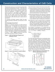
Manufacturing Process<br />
This is a two-step process of chip manufacturing and thermistor<br />
assembly. Manufactured chips are processed by metal oxide powders<br />
into ceramic sheets. These sheets are metalized with silver to allow<br />
for electrical contact. After metalization, the ceramic sheets are<br />
diced into chips. Each chip is tested to meet our superior quality<br />
standards.<br />
After a chip has been manufactured and tested, leads are attached.<br />
The chip is trimmed to meet the specified tolerance, and then a<br />
protective coating is added. Further customizing of the assembly<br />
can be done by adding housings, cables, and connectors.<br />
Thermistor quality is assured with in-process inspection and<br />
Statistical Process Control (SPC). This process takes place at each<br />
manufacturing and assembly step. All finished products are 100%<br />
tested both electrically and mechanically to guarantee all specifications<br />
are met.<br />
Resistance-Temperature (R/T) Curves and<br />
Negative Temperature Coefficient<br />
Nine different materials are made, each with its own unique and<br />
predictable resistance-temperature characteristics. These characteristics<br />
are called ‘curves’. <strong>Thermistors</strong> are most often specified by their<br />
curve and by their resistance value at 25°C.<br />
The <strong>NTC</strong> (Negative Temperature Coefficient) is the negative percent<br />
resistance change per degree C. Our thermistors have <strong>NTC</strong> values<br />
at 25°C ranging from -3.7%/°C to -6.4%/°C. Resistance values at<br />
25°C range from 300 ohms to 1 meg ohms. The tables on pages<br />
26-27 detail this information.<br />
Self-heating is desirable in applications such as air flow measurement<br />
and liquid level control. Standard epoxy or phenolic coated thermistors<br />
with a 0.095” O.D., have a maximum power rating of 30 milliwatts at<br />
25°C to 1 milliwatt at 100°C.<br />
Beta<br />
The Beta value describes the steepness of R/T curve. The larger<br />
value Beta equals a steeper R/T curve. The Beta value of a thermistor<br />
is one way to characterize its resistance temperature relationship.<br />
Beta is dependent on two reference temperatures. <strong>Selco</strong> <strong>Products</strong><br />
uses 25°C and 85°C as its standard. Beta is calculated as follows:<br />
$ T2/T1 = Ln(RT2/RT1)/(1T2 - 1T/1)<br />
Temperature is in degrees Kelvin; RT1 is the resistance at<br />
temperature T1; RT2 is the resistance at temperature T2.<br />
Steinhart-Hart Equation<br />
The Steinhart-Hart Equation is an empirically developed polynomial<br />
which best represents the resistance-temperature relationships of<br />
<strong>NTC</strong> thermistors. The Steinhart-Hart Equation is more accurate<br />
than previous methods. Specifically, it is more accurate over wider<br />
temperature ranges. To solve temperature when resistance is<br />
known, the form of the equation is:<br />
1/T=a+b(Ln(R))+c(Ln(R)) 3<br />
To solve for resistance when temperature is known, the form of the<br />
equation is:<br />
R=e(exp)[-a/2+(a 2 /4+a 3 /27) -2 ) -3 +(-a/2-(a 2 /4+a 3 /27) 2 ) 3 ]<br />
where alpha = (a-1/T)/c and $ = b/c<br />
For both forms of the equation T is temperature expressed in<br />
degrees Kelvin; a, b, and c can be solved simultaneously using the<br />
following:<br />
1/T1=a+b(LnR1)+c(LnR1) 3<br />
1/T2=a+b(LnR2)+c(LnR2) 3<br />
1/T3=a+b(LnR3)+c(LnR3) 3<br />
Thermal Time Constant<br />
Time constant, expressed in seconds, is the time required for a<br />
thermistor to indicate 63.2% of a newly impressed temperature. The<br />
time constant of a thermistor is directly affected by the mass of the<br />
thermistor and thermal coupling to the environment. An epoxy or<br />
phenolic coated thermistor with a 0.095” O.D., will typically have a<br />
time constant of 0.75 seconds in stirred oil and 10 seconds in still<br />
air.<br />
Dissipation Constant<br />
Dissipation constant is the power required to raise the temperature<br />
of a thermistor 1°C above the surrounding environment. Power is<br />
expressed in watts. The dissipation constant of a thermistor with a<br />
0.095” O.D., coated with epoxy or phenolic, is typically 13 mW/°C in<br />
stirred oil and 2 mW/°C in still air.<br />
Voltage/Current Requirements<br />
Very low current is required for a thermistor being used in temperature<br />
measurement, control or compensation applications. Current levels<br />
should typically be less than 100mA for a thermistor to dissipate<br />
“zero power”. As previously discussed, power dissipation for a<br />
thermistor in still air is approximately 2mW/°C. Therefore, in order<br />
to keep the thermal error (self-heat) below 0.1°C, the power<br />
dissipation must be less than 0.2 mW.<br />
The data calculated by these equations will be accurate to better<br />
than ±0.01°C when -40°C is less than or equal to 150°C and |T1-T2|<br />
is less than or equal to 50°C and |T2-T3| is less than or equal to<br />
50°C and T1, T2, and T3 are evenly spaced.<br />
Maximum Temperature Rating/Recommended Operating Ranges<br />
Our thermistors may be intermittently cycled at temperatures from<br />
-50°C to 150°C. Stability is achieved when the thermistors are<br />
stored at temperatures less than 50°C and operated continuously at<br />
temperatures less than 100°C. The DT Series thermistor has a<br />
temperature range from -50°C to +250°C. For interchangeable<br />
thermistors, optimum stability is achieved when the thermistors are<br />
operated at temperatures within the specified temperature range.<br />
Stability<br />
Years of experience in thermistor manufacturing, coupled with<br />
stringent process controls, ensures that highly stable thermistors are<br />
produced. In fact, our thermistors typically exhibit less than 0.02°C<br />
thermometric drift per year when stored or operated at temperatures<br />
less than 50°C. The stability of a thermistor is greatly dependent on<br />
environmental conditions such as humidity, excessive temperatures<br />
and thermal shock. These effects should be minimized to guarantee<br />
stability.<br />
(775) 674-5100 (800) 257-3526 FAX (775) 674-5111 E-mail: sales@selcoproducts.com<br />
www.selcoproducts.com<br />
25
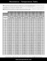
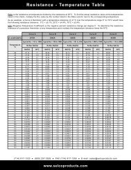
Resistance - Temperature Table<br />
Ratio is the resistance at temperature divided by the resistance at 25°C. To find the actual resistance value at the temperatures listed in the<br />
charts, multiply the R25 value by the number listed in the Ratio column next to the corresponding temperature.<br />
As an example, a Curve A thermistor with a temperature tolerance of ±1°C over the temperature range 0° to 70°C would have the following<br />
resistance tolerance: 0°C = ±5.1%; 25°C = ±4.4%; 70°C = ±3.4%<br />
<strong>NTC</strong> (Negative Temperature Coefficient) is the negative percent resistance change per degree C. To determine the resistance tolerance of a<br />
precision thermistor at any temperature point multiply the temperature tolerance times the <strong>NTC</strong>.<br />
Curve A<br />
Curve B<br />
Curve C<br />
Curve D<br />
Curve E<br />
$ at 25°C/85°C<br />
3977K<br />
3942K<br />
3695K<br />
4262K<br />
4434K<br />
$ at 0°C/50°C 3892K 3813K 3575K 4141K 4276K<br />
Typical R25 = 1K to 100K<br />
Typical R25 = 10K to 100K<br />
Typical R25 = 5K to 20K<br />
Typical R25 = 25K to 100K<br />
Typical R25 = 1K to 200K<br />
Temperature<br />
°C<br />
RT/R25 RATIO<br />
RT/R25 RATIO<br />
RT/R25 RATIO<br />
RT/R25 RATIO<br />
RT/R25 RATIO<br />
RATIO<br />
<strong>NTC</strong><br />
RATIO<br />
<strong>NTC</strong><br />
RATIO<br />
<strong>NTC</strong><br />
RATIO<br />
<strong>NTC</strong><br />
RATIO<br />
<strong>NTC</strong><br />
-50<br />
-45<br />
-40<br />
-35<br />
-30<br />
-25<br />
-20<br />
-15<br />
-10<br />
-5<br />
0<br />
5<br />
10<br />
15<br />
20<br />
25<br />
30<br />
35<br />
37<br />
40<br />
45<br />
50<br />
55<br />
60<br />
65<br />
70<br />
75<br />
80<br />
85<br />
90<br />
95<br />
100<br />
105<br />
110<br />
115<br />
120<br />
125<br />
130<br />
135<br />
140<br />
145<br />
150<br />
67.13<br />
47.26<br />
33.69<br />
24.29<br />
17.71<br />
13.05<br />
9.711<br />
7.297<br />
5.534<br />
4.234<br />
3.266<br />
2.540<br />
1.991<br />
1.572<br />
1.249<br />
1.000<br />
0.8056<br />
0.6530<br />
0.6014<br />
0.5325<br />
0.4367<br />
0.3601<br />
0.2985<br />
0.2487<br />
0.2082<br />
0.1752<br />
0.1480<br />
0.1256<br />
0.1071<br />
0.09161<br />
0.07870<br />
0.06786<br />
0.05873<br />
0.05100<br />
0.04444<br />
0.03885<br />
0.03408<br />
0.02997<br />
0.02645<br />
0.02340<br />
0.02076<br />
0.01487<br />
7.1<br />
6.9<br />
6.7<br />
6.4<br />
6.2<br />
6.0<br />
5.8<br />
5.6<br />
5.4<br />
5.3<br />
5.1<br />
5.0<br />
4.8<br />
4.7<br />
4.5<br />
4.4<br />
4.3<br />
4.1<br />
4.1<br />
4.0<br />
3.9<br />
3.8<br />
3.7<br />
3.6<br />
3.5<br />
3.4<br />
3.3<br />
3.2<br />
3.2<br />
3.1<br />
3.0<br />
2.9<br />
2.9<br />
2.8<br />
2.7<br />
2.7<br />
2.6<br />
2.5<br />
2.5<br />
2.4<br />
2.4<br />
2.3<br />
56.39<br />
40.56<br />
29.48<br />
21.64<br />
16.03<br />
11.99<br />
9.040<br />
6.875<br />
5.270<br />
4.071<br />
3.168<br />
2.483<br />
1.959<br />
1.556<br />
1.244<br />
1.000<br />
0.8088<br />
0.6579<br />
0.6066<br />
0.5380<br />
0.4423<br />
0.3654<br />
0.3034<br />
0.2531<br />
0.2121<br />
0.1785<br />
0.1508<br />
0.1280<br />
0.1091<br />
0.09327<br />
0.08006<br />
0.06897<br />
0.05962<br />
0.05171<br />
0.04500<br />
0.03928<br />
0.03439<br />
0.03020<br />
0.02660<br />
0.02349<br />
0.02080<br />
0.01846<br />
6.7<br />
6.5<br />
6.3<br />
6.1<br />
5.9<br />
5.7<br />
5.6<br />
5.4<br />
5.2<br />
5.1<br />
4.9<br />
4.8<br />
4.7<br />
4.5<br />
4.4<br />
4.3<br />
4.2<br />
4.1<br />
4.0<br />
4.0<br />
3.9<br />
3.8<br />
3.7<br />
3.6<br />
3.5<br />
3.4<br />
3.3<br />
3.2<br />
3.2<br />
3.1<br />
3.0<br />
2.9<br />
2.9<br />
2.8<br />
2.8<br />
2.7<br />
2.6<br />
2.6<br />
2.5<br />
2.5<br />
2.4<br />
2.4<br />
44.13<br />
32.36<br />
23.97<br />
17.92<br />
13.52<br />
10.29<br />
7.891<br />
6.102<br />
4.754<br />
3.731<br />
2.949<br />
2.346<br />
1.879<br />
1.514<br />
1.227<br />
1.000<br />
0.8196<br />
0.6754<br />
0.6260<br />
0.5594<br />
0.4655<br />
0.3893<br />
0.3270<br />
0.2760<br />
0.2338<br />
0.1990<br />
0.1700<br />
0.1457<br />
0.1254<br />
0.1084<br />
0.09392<br />
0.08168<br />
0.07127<br />
0.06237<br />
0.05476<br />
0.04821<br />
0.04257<br />
0.03769<br />
0.03346<br />
0.02979<br />
0.02658<br />
0.02377<br />
6.3<br />
6.1<br />
5.9<br />
5.3<br />
5.6<br />
5.4<br />
5.2<br />
5.1<br />
4.9<br />
4.8<br />
4.6<br />
4.5<br />
4.4<br />
4.3<br />
4.1<br />
4.0<br />
3.9<br />
3.8<br />
3.8<br />
3.7<br />
3.6<br />
3.5<br />
3.4<br />
3.4<br />
3.3<br />
3.2<br />
3.1<br />
3.0<br />
3.0<br />
2.9<br />
2.8<br />
2.8<br />
2.7<br />
2.6<br />
2.6<br />
2.5<br />
2.5<br />
2.4<br />
2.4<br />
2.3<br />
2.3<br />
2.2<br />
82.36<br />
57.30<br />
40.34<br />
28.72<br />
20.67<br />
15.02<br />
11.03<br />
8.174<br />
6.113<br />
4.611<br />
3.507<br />
2.689<br />
2.077<br />
1.617<br />
1.267<br />
1.000<br />
0.7943<br />
0.6349<br />
0.5815<br />
0.5106<br />
0.4130<br />
0.3359<br />
0.2747<br />
0.2259<br />
0.1866<br />
0.1549<br />
0.1293<br />
0.1083<br />
0.09115<br />
0.07704<br />
0.06538<br />
0.05570<br />
0.04764<br />
0.04089<br />
0.03522<br />
0.03045<br />
0.02641<br />
0.02298<br />
0.02006<br />
0.01756<br />
0.01542<br />
0.01358<br />
7.4<br />
7.1<br />
6.9<br />
6.7<br />
6.5<br />
6.3<br />
6.1<br />
5.9<br />
5.7<br />
5.6<br />
5.4<br />
5.2<br />
5.1<br />
4.9<br />
4.8<br />
4.7<br />
4.5<br />
4.4<br />
4.4<br />
4.3<br />
4.2<br />
4.1<br />
4.0<br />
3.9<br />
3.8<br />
3.7<br />
3.6<br />
3.5<br />
3.4<br />
3.3<br />
3.2<br />
3.2<br />
3.1<br />
3.0<br />
2.9<br />
2.9<br />
2.8<br />
2.8<br />
2.7<br />
2.6<br />
2.6<br />
2.5<br />
89.69<br />
62.25<br />
43.69<br />
30.98<br />
22.20<br />
16.06<br />
11.73<br />
8.644<br />
6.425<br />
4.816<br />
3.638<br />
2.770<br />
2.125<br />
1.642<br />
1.277<br />
1.000<br />
0.7881<br />
0.6250<br />
0.5706<br />
0.4986<br />
0.4001<br />
0.3228<br />
0.2619<br />
0.2136<br />
0.1750<br />
0.1441<br />
0.1193<br />
0.09915<br />
0.08278<br />
0.06941<br />
0.05844<br />
0.04940<br />
0.04192<br />
0.03571<br />
0.03053<br />
0.02619<br />
0.02254<br />
0.01947<br />
0.01687<br />
0.01467<br />
0.01279<br />
0.01118<br />
7.4<br />
7.2<br />
7.0<br />
6.8<br />
6.6<br />
6.4<br />
6.2<br />
6.0<br />
5.8<br />
5.7<br />
5.5<br />
5.4<br />
5.2<br />
5.1<br />
5.0<br />
4.8<br />
4.7<br />
4.6<br />
4.5<br />
4.5<br />
4.3<br />
4.2<br />
4.1<br />
4.0<br />
3.9<br />
3.8<br />
3.7<br />
3.7<br />
3.6<br />
3.5<br />
3.4<br />
3.3<br />
3.2<br />
3.2<br />
3.1<br />
3.0<br />
3.0<br />
2.9<br />
2.8<br />
2.8<br />
2.7<br />
2.7<br />
(775) 674-5100 (800) 257-3526 FAX (775) 674-5111 E-mail: sales@selcoproducts.com<br />
26<br />
www.selcoproducts.com
Resistance - Temperature Table<br />
Curve F<br />
Curve G<br />
Curve H<br />
Curve I<br />
Curve K<br />
Curve P<br />
$ at 25°C/85°C<br />
3435K<br />
4390K<br />
4847K<br />
3535K<br />
3485K<br />
4144K<br />
$ at 0°C/50°C 3320K<br />
4269K 4669K 3419K<br />
3405K 3988K<br />
Typical R25 = 10K<br />
Typical R25 = 10K<br />
Typical R25 = 1MEG<br />
Typical R25 = 2K to 20K<br />
Typical R25 = 200 to 2K<br />
Typical R25 = 100K<br />
Temperature<br />
°C<br />
RT/R25 RATIO<br />
RT/R25 RATIO<br />
RT/R25 RATIO<br />
RT/R25 RATIO<br />
RT/R25 RATIO<br />
RT/R25 RATIO<br />
RATIO<br />
<strong>NTC</strong><br />
RATIO<br />
<strong>NTC</strong><br />
RATIO<br />
<strong>NTC</strong><br />
RATIO<br />
<strong>NTC</strong><br />
RATIO<br />
<strong>NTC</strong><br />
RATIO<br />
<strong>NTC</strong><br />
-50<br />
-45<br />
-40<br />
-35<br />
-30<br />
-25<br />
-20<br />
-15<br />
-10<br />
-5<br />
0<br />
5<br />
10<br />
15<br />
20<br />
25<br />
30<br />
35<br />
37<br />
40<br />
45<br />
50<br />
55<br />
60<br />
65<br />
70<br />
75<br />
80<br />
85<br />
90<br />
95<br />
100<br />
105<br />
110<br />
115<br />
120<br />
125<br />
130<br />
135<br />
140<br />
145<br />
150<br />
32.95<br />
24.77<br />
18.85<br />
14.41<br />
11.13<br />
8.643<br />
6.777<br />
5.341<br />
4.247<br />
3.39<br />
2.728<br />
2.205<br />
1.796<br />
1.469<br />
1.209<br />
1.000<br />
0.8313<br />
0.694<br />
0.5827<br />
0.4912<br />
0.4161<br />
0.3536<br />
0.302<br />
0.2588<br />
0.2228<br />
0.1924<br />
0.1668<br />
0.1451<br />
0.1266<br />
0.1108<br />
0.09731<br />
0.08572<br />
0.07576<br />
6.2<br />
6.0<br />
5.8<br />
5.6<br />
5.4<br />
5.2<br />
5.0<br />
4.8<br />
4.7<br />
4.5<br />
4.4<br />
4.2<br />
4.1<br />
4.0<br />
3.9<br />
3.7<br />
3.6<br />
3.5<br />
3.4<br />
3.3<br />
3.2<br />
3.1<br />
3.1<br />
3.0<br />
2.9<br />
2.8<br />
2.7<br />
2.7<br />
2.6<br />
3.0<br />
2.5<br />
2.4<br />
2.4<br />
95.84<br />
65.66<br />
45.72<br />
32.06<br />
22.82<br />
16.37<br />
11.91<br />
8.727<br />
6.472<br />
4.834<br />
3.65<br />
2.772<br />
2.125<br />
1.64<br />
1.277<br />
1.000<br />
0.7888<br />
0.6259<br />
0.5003<br />
0.402<br />
0.3251<br />
0.2642<br />
0.2161<br />
0.1775<br />
0.1466<br />
0.1215<br />
0.1013<br />
0.08483<br />
0.07135<br />
0.06025<br />
0.05111<br />
0.04351<br />
0.0372<br />
0.0319<br />
0.02746<br />
0.02371<br />
8.1<br />
7.8<br />
7.5<br />
7.2<br />
7.0<br />
6.7<br />
6.5<br />
6.3<br />
6.0<br />
5.8<br />
5.7<br />
5.5<br />
5.3<br />
5.1<br />
5.0<br />
4.8<br />
4.7<br />
4.5<br />
4.4<br />
4.3<br />
4.1<br />
4.0<br />
3.9<br />
3.8<br />
3.7<br />
3.6<br />
3.5<br />
3.4<br />
3.3<br />
3.3<br />
3.2<br />
3.1<br />
3.0<br />
2.9<br />
2.9<br />
2.8<br />
14.65<br />
10.51<br />
7.607<br />
5.556<br />
4.093<br />
3.041<br />
2.277<br />
1.718<br />
1.306<br />
1.000<br />
0.7710<br />
0.5984<br />
0.5417<br />
0.4675<br />
0.3675<br />
0.2907<br />
0.2312<br />
0.1580<br />
0.1488<br />
0.1204<br />
0.09784<br />
0.07993<br />
0.06561<br />
0.05411<br />
0.04483<br />
0.03730<br />
0.03117<br />
0.02615<br />
0.02203<br />
0.01863<br />
0.01581<br />
0.01347<br />
0.01152<br />
0.00988<br />
0.00850<br />
0.00734<br />
6.1<br />
6.6<br />
6.4<br />
6.2<br />
6.0<br />
5.9<br />
5.7<br />
5.6<br />
5.4<br />
5.3<br />
5.1<br />
5.0<br />
5.0<br />
4.9<br />
4.8<br />
4.6<br />
4.5<br />
4.4<br />
4.3<br />
4.2<br />
4.1<br />
4.0<br />
3.9<br />
3.8<br />
3.7<br />
3.6<br />
3.6<br />
3.5<br />
3.4<br />
3.3<br />
3.2<br />
3.2<br />
3.1<br />
3.0<br />
3.0<br />
2.9<br />
20.68<br />
15.67<br />
11.998<br />
9.241<br />
7.189<br />
5.623<br />
4.439<br />
3.518<br />
2.812<br />
2.258<br />
1.828<br />
1.486<br />
1.16<br />
1.000<br />
0.8267<br />
0.6865<br />
0.6384<br />
0.5735<br />
0.4809<br />
0.4054<br />
0.3430<br />
0.2916<br />
0.2488<br />
0.2133<br />
0.1834<br />
0.1584<br />
0.13724<br />
0.11929<br />
0.10402<br />
0.09102<br />
0.07990<br />
0.07038<br />
0.06216<br />
0.05505<br />
0.04888<br />
0.04351<br />
0.03883<br />
0.03472<br />
0.03112<br />
0.02796<br />
6.0<br />
5.7<br />
5.5<br />
5.3<br />
5.2<br />
5.0<br />
4.8<br />
4.7<br />
4.5<br />
4.4<br />
4.2<br />
4.1<br />
4.0<br />
3.9<br />
3.7<br />
3.6<br />
3.6<br />
3.5<br />
3.4<br />
3.3<br />
3.2<br />
3.2<br />
3.1<br />
3.0<br />
2.9<br />
2.8<br />
2.8<br />
2.7<br />
2.6<br />
2.6<br />
2.5<br />
2.4<br />
2.4<br />
2.3<br />
2.3<br />
2.2<br />
2.2<br />
2.1<br />
2.1<br />
2.0<br />
39.18<br />
28.88<br />
21.50<br />
16.18<br />
12.28<br />
9.415<br />
7.278<br />
5.673<br />
4.457<br />
3.528<br />
2.813<br />
2.259<br />
1.826<br />
1.485<br />
1.215<br />
1.000<br />
0.8277<br />
0.6887<br />
0.6408<br />
0.5760<br />
0.4842<br />
0.4089<br />
0.3469<br />
0.2956<br />
0.2530<br />
0.2174<br />
0.1875<br />
0.1623<br />
0.1411<br />
0.1230<br />
0.1076<br />
0.09450<br />
0.08322<br />
0.07351<br />
0.06512<br />
0.05786<br />
0.05154<br />
6.2<br />
6.0<br />
5.8<br />
5.6<br />
5.4<br />
5.2<br />
5.1<br />
4.9<br />
4.7<br />
4.6<br />
4.5<br />
4.3<br />
4.2<br />
4.1<br />
4.0<br />
3.8<br />
3.7<br />
3.6<br />
3.6<br />
3.5<br />
3.4<br />
3.3<br />
3.2<br />
3.2<br />
3.1<br />
3.0<br />
2.9<br />
2.8<br />
2.8<br />
2.7<br />
2.6<br />
2.6<br />
2.5<br />
2.5<br />
2.4<br />
2.3<br />
2.3<br />
33.58<br />
24.41<br />
17.91<br />
13.26<br />
9.898<br />
7.452<br />
5.655<br />
4.325<br />
3.331<br />
2.585<br />
2.019<br />
1.587<br />
1.256<br />
1.000<br />
0.8008<br />
0.6450<br />
0.5924<br />
0.5224<br />
0.4253<br />
0.3480<br />
0.2862<br />
0.2365<br />
0.1964<br />
0.1638<br />
0.1372<br />
0.1154<br />
0.09742<br />
0.08260<br />
0.07030<br />
0.06005<br />
0.05148<br />
0.04429<br />
0.03823<br />
0.03310<br />
0.02876<br />
0.02506<br />
0.02190<br />
0.01920<br />
0.0168<br />
0.01487<br />
6.5<br />
6.3<br />
6.3<br />
5.9<br />
5.8<br />
5.6<br />
5.4<br />
5.3<br />
5.1<br />
5.0<br />
4.9<br />
4.7<br />
4.6<br />
4.5<br />
4.4<br />
4.3<br />
4.2<br />
4.2<br />
4.1<br />
4.0<br />
3.9<br />
3.8<br />
3.4<br />
3.6<br />
3.5<br />
3.4<br />
3.3<br />
3.3<br />
3.2<br />
3.1<br />
3.0<br />
3.0<br />
2.9<br />
2.8<br />
2.8<br />
2.7<br />
2.7<br />
2.6<br />
2.6<br />
2.5<br />
(775) 674-5100 (800) 257-3526 FAX (775) 674-5111 E-mail: sales@selcoproducts.com<br />
www.selcoproducts.com<br />
27
Application Notes<br />
<strong>NTC</strong> Thermistor Applications<br />
Introduction<br />
Our <strong>NTC</strong> chip thermistors are excellent solutions in applications<br />
requiring temperature measurement and compensation from -50°<br />
to 150°C.<br />
RTDs, thermocouples and silicon semiconductors cannot compete<br />
with the thermistor’s sensitive response to temperature. This<br />
sensitivity is crucial for accurate temperature measurement.<br />
Figure 1: Wheatstone Bridge - Voltage Mode<br />
T1 = 10K ohm “A” Curve<br />
1 VOLT<br />
R1 = 4980 ohm<br />
R2 = 4980 ohm<br />
R3 = 10K ohm<br />
T1<br />
OUTPUT<br />
+ -<br />
R3<br />
Unlike RTDs and thermocouples, thermistors are virtually<br />
unaffected by lead resistance. This makes <strong>NTC</strong> thermistors the<br />
sensor of choice for remote sensing applications. With their<br />
excellent long term stability characteristics, design engineers utilize<br />
thermistors in critical applications for the medical, military,<br />
aerospace, industrial and scientific industries.<br />
R1<br />
METER<br />
R2<br />
Systems utilizing thermistors are less expensive to produce than<br />
other solutions because fewer associated components are required<br />
for a high performance system. Chip thermistors can be ordered<br />
with tight tolerances to ±0.1°C, eliminating the costly calibration<br />
process required by temperature sensors such as silicon<br />
semiconductors, RTDs, thermocouples and glass beaded and disk<br />
thermistors with loose tolerances.<br />
<strong>NTC</strong> thermistors provide the design engineer with desirable sensor<br />
performance advantages in a variety of applications. The following<br />
notes provide a few examples of how to utilize the <strong>NTC</strong> thermistor.<br />
“Zero Power” Sensing - Dissipation Constant<br />
When utilizing a thermistor for temperature measurement, control,<br />
and compensation applications, it is very important not to “self-heat”<br />
the thermistor. Power, in the form of heat, is produced when current<br />
is passed through the thermistor. Since a thermistor’s resistance<br />
changes when temperature changes, this “self generated heat” will<br />
change the resistance of the thermistor, producing an erroneous<br />
reading.<br />
The power dissipation constant is the amount of power required<br />
to raise a thermistor’s body temperature 1°C. A standard chip<br />
thermistor has a power dissipation constant of approximately<br />
2mW/°C in still air. In order to keep the “self-heat” error below 0.1°C<br />
power dissipation must be below 0.2mW. Very low current levels are<br />
required to obtain such a lower power dissipation factor. This mode<br />
of operation is called “zero power” sensing.<br />
Thermistor Linearization - Voltage Mode<br />
Wheatstone Bridge - Voltage Mode<br />
Figure 2: Wheatstone Bridge - Voltage Mode<br />
VOLTAGE OUTPUT (mV)<br />
200<br />
100<br />
0<br />
25<br />
ACTUAL<br />
OUTPUT RESPONSE<br />
30 35 40 45<br />
O<br />
TEMPERATURE ( C)<br />
NOMINAL<br />
LINEAR RESPONSE<br />
MAXIMUM<br />
LINEAR DEVIATION<br />
Figure 3: Wheatstone Bridge - Voltage Mode<br />
T1 = 30K ohm “B” Curve<br />
T2 = 6K ohm “A” Curve<br />
R1 = 5420 ohm<br />
R2 = 3970 ohm<br />
R3 = 3970 ohm<br />
R4 = 24720 ohm<br />
T2<br />
R1<br />
R2<br />
1 VOLT<br />
T1<br />
OUTPUT<br />
+ -<br />
METER<br />
R4<br />
R3<br />
To produce a voltage output that varies linearly with temperature,<br />
utilize the <strong>NTC</strong> thermistor as the active leg in a Wheatstone Bridge.<br />
As temperature increases, the voltage output increases. The circuit<br />
in Figure 1 produces an output voltage that is linear with ±0.06°C<br />
from 25°C to 45°C. This circuit is designed to produce 1V at 25°C<br />
and 200mW at 45°C; this is achieved by the selection of R2 and R3.<br />
The value of R1 is selected to best provide linearization of the 10K<br />
ohm thermistor over the 25°C to 45°C temperature range. Figure 2<br />
illustrates the output voltage of the Wheatstone Bridge as a function<br />
of temperature.<br />
The circuit in Figure 3 provides improved output accuracy over a<br />
wide temperature range by substituting a 6K/30K ohm thermistor<br />
network in place of the single thermistor in the Wheatstone Bridge.<br />
This circuit is designed to provide 0V at 0°C and 537mV at 100°C.<br />
The maximum linear deviation of this circuit is ±0.234°C from 0°C to<br />
100°C.<br />
(775) 674-5100 (800) 257-3526 FAX (775) 674-5111 E-mail: sales@selcoproducts.com<br />
28<br />
www.selcoproducts.com
Application Notes<br />
Thermistor Linearization<br />
Operational Amplifier - Resistance Mode<br />
A linear voltage output that varies with temperature can also be<br />
produced by utilizing an operational amplifier and a linearized<br />
thermistor network as illustrated in Figure 4. The voltage output<br />
decreases linearly as temperature increases. This circuit may be<br />
calibrated by adjusting R3 for an output voltage of 200mW at 25°C<br />
and 0V at 45°C.<br />
Figure 4: Linearization - Resistance Mode<br />
T1 = 10K ohm “A” Curve<br />
R1<br />
R1 = 4980 ohm<br />
R2 = 5K ohm<br />
T1<br />
R3 = 10K ohm potentiometer<br />
R3<br />
R2<br />
-<br />
+<br />
Temperature Measurement and Control<br />
Digital Thermometer<br />
The most common application for the <strong>NTC</strong> thermistor is temperature<br />
measurement. Accurate temperature measurement can easily be<br />
accomplished by interfacing a Wheatstone Bridge, 6K/30K ohm<br />
thermistor network and a digital voltmeter integrated circuit as<br />
illustrated in Figure 5. The IC consist of an analog to digital<br />
converter with built-in 3-1/2 digit LCD driver providing resolution of<br />
0.1°C. Using the 6K/30K ohm thermistor network makes it possible<br />
to achieve an overall system accuracy of ±0.4°C from 0°C to 100°C.<br />
This digital thermometer can easily be interfaced with additional<br />
circuitry to provide a temperature control circuit with a digital display.<br />
Micro Controller System<br />
The advent of low cost micro controllers used with precision<br />
interchangeable <strong>NTC</strong> thermistors, provides the design engineer with<br />
unlimited design possibilities for temperature measurement and<br />
control systems. These systems are relatively inexpensive to<br />
produce yet offer very high temperature accuracy and various<br />
software controlled outputs.<br />
For example, a micro controller system utilizing remote thermistor<br />
sensors can monitor and control the temperature in several<br />
locations in an office building. For this case, the micro controller is<br />
comprised of a built-in microprocessor, analog to digital converter,<br />
RAM and several digital inputs/outputs. The complete system<br />
Figure 6 utilizes the micro controller, multiplexer, EPROM, digital<br />
display, keypad and display driver.<br />
The micro controller is programmed in assembler language. The<br />
temperature measurement is calculated within the micro controller<br />
using the resistance versus temperature algorithm and the a, b<br />
and c, constants for the specific thermistor resistance and curve<br />
material. Refer to the Steinhart Equation on page 5. An alternative<br />
method to convert the thermistor resistance to temperature is to<br />
program a “look-up” table in EPROM. After programming, the micro<br />
controller tells the multiplexer to send back temperature data from<br />
a particular zone (room in the office building) and converts the<br />
resistance of the thermistor into a temperature reading.<br />
Figure 5: Digital Thermometer<br />
R7 = 1.50K ohm<br />
R8 = 100K ohm<br />
R9 = 470K ohm<br />
R10 = 15K ohm<br />
C1 = 100 pF<br />
C2 = 0.22<br />
C4 = 0.1<br />
T1<br />
T2<br />
R2<br />
R2<br />
R4<br />
R5<br />
R6<br />
R7<br />
R10<br />
R3<br />
C4<br />
R8<br />
C1<br />
40 39 38<br />
36<br />
34<br />
33<br />
Figure 6: Micro Controller System<br />
THERMISTOR<br />
ZONE 1<br />
THERMISTOR<br />
ZONE 2<br />
THERMISTOR<br />
ZONE 3<br />
THERMISTOR<br />
ZONE 4<br />
THERMISTOR<br />
ZONE 5<br />
THERMISTOR<br />
ZONE 6<br />
MULTI-<br />
PLEXER<br />
31<br />
30<br />
36<br />
A/D<br />
INPUT<br />
KEYPAD<br />
1<br />
R9<br />
C2<br />
32 26<br />
DISPLAY<br />
70 O<br />
C<br />
DISPLAY DRIVER<br />
MICRO<br />
CONTROLLER<br />
EPROM<br />
C3<br />
29 28 27<br />
2<br />
3<br />
20<br />
22<br />
25<br />
21<br />
+9V<br />
S1<br />
HEAT/AC<br />
ZONE1<br />
HEAT/AC<br />
ZONE 2<br />
HEAT/AC<br />
ZONE 3<br />
HEAT/AC<br />
ZONE 4<br />
HEAT/AC<br />
ZONE 5<br />
HEAT/AC<br />
ZONE 6<br />
TO<br />
LCD<br />
The micro controller can then turn on or off the heating or air<br />
conditioning systems in a specific zone.<br />
The thermistor/micro controller system can be used for security,<br />
temperature control, monitoring activities and many other<br />
applications. The possibilities are endless.<br />
(775) 674-5100 (800) 257-3526 FAX (775) 674-5111 E-mail: sales@selcoproducts.com<br />
www.selcoproducts.com<br />
29
Application Notes<br />
Temperature Compensation<br />
<strong>NTC</strong> thermistors can be used to compensate for the temperature<br />
coefficient response of various components such as crystal<br />
oscillators, mechanical meters and infrared LEDs. A thermistor/<br />
resistor network Figure 7 is placed in series with a PTC component<br />
requiring compensation. The resistor values are selected to provide<br />
the proper <strong>NTC</strong> slope to offset the PTC component. The net effect<br />
is a constant circuit response that is independent of temperature.<br />
“Self-Heat” Sensing Applications<br />
Figure 7: Temperature Compensation<br />
T1<br />
R1<br />
R2<br />
COPPER COIL<br />
METER<br />
RESPONSE<br />
METER CIRCUIT<br />
RESPONSE<br />
TEMPERATURE<br />
PTC COMPONENT<br />
RESPONSE<br />
<strong>NTC</strong> THERMISTOR<br />
NETWORK<br />
To “self-heat” a thermistor, it must be subjected to power levels that<br />
raise the thermistor’s body temperature above the environmental<br />
surroundings. Self-heat applications include the sensing of liquid,<br />
air level, and flow rates. This application is dependent on the fact<br />
that the environment surrounding a thermistor directly affects the<br />
amount of power the thermistor can dissipate. For example,<br />
submerged in liquid, a thermistor can typically dissipate 500% to<br />
600% more power than it can air.<br />
Therefore, a thermistor being “self-heated” in air is able to dissipate<br />
much more power when transferred to a fluid environment. This<br />
increase in power dissipation generates a significant increase in<br />
resistance. It is this change in resistance, which makes it possible<br />
to sense the fluid level.<br />
A simple liquid level control system can be designed by putting a<br />
thermistor in series with a coil Figure 8, which operates a valve that<br />
releases the liquid in the tank. The thermistor is placed in the tank<br />
and operated in a “self-heat” mode.<br />
In air, the thermistor’s resistance is low and allows enough current<br />
flow to energize the relay coil and keep the relay contact closed.<br />
When the fluid level in the tank surrounds the thermistor, its<br />
resistance increases and de-energizes the relay, which opens a<br />
valve and releases the fluid. As the fluid is released from the tank,<br />
the thermistor’s resistance decreases and the relay coil energizes<br />
and closes the valve.<br />
Fuel injection in automobiles utilize the thermistor in the “self-heat”<br />
mode in order to properly control the air/fuel mixture. Forced air<br />
heaters may use the <strong>NTC</strong> thermistor in the “self-heat” mode in order<br />
to maintain proper air flow characteristics. This technology is<br />
utilized to monitor the flow rate and level of air and fluids in a<br />
variety of applications.<br />
Figure 8: Self-Heat Applications<br />
T1<br />
VALVE<br />
RELAY<br />
COIL<br />
04/10-mb<br />
(775) 674-5100 (800) 257-3526 FAX (775) 674-5111 E-mail: sales@selcoproducts.com<br />
30<br />
www.selcoproducts.com
8780 Technology Way Reno, NV 89521-5908<br />
(800) 257-3526 (775) 674-5100 FAX (775) 674-5111<br />
E-mail: sales@selcoproducts.com<br />
www.selcoproducts.com<br />
THERMOSTATS THERMISTORS ELECTRONIC CONTROLS<br />
CONTROL KNOBS DIGITAL PANEL METERS<br />
AEROSPACE AUTOMOTIVE BATTERY PACKS COMMUNICATIONS