

GE Consumer & Industrial - G E Power Controls
GE Consumer & Industrial - G E Power Controls
GE Consumer & Industrial - G E Power Controls

Create successful ePaper yourself
Turn your PDF publications into a flip-book with our unique Google optimized e-Paper software.
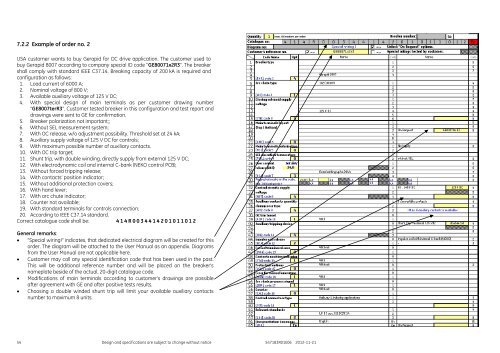
7.2.2 Example of order no. 2<br />
USA customer wants to buy Gerapid for DC drive application. The customer used to<br />
buy Gerapid 8007 according to company special ID code “<strong>GE</strong>80071x2R3”. The breaker<br />
shall comply with standard IEEE C37.14. Breaking capacity of 200 kA is required and<br />
configuration as follows:<br />
1. Load current of 6000 A;<br />
2. Nominal voltage of 800 V;<br />
3. Available auxiliary voltage of 125 V DC;<br />
4. With special design of main terminals as per customer drawing number<br />
“<strong>GE</strong>8007terR3”. Customer tested breaker in this configuration and test report and<br />
drawings were sent to <strong>GE</strong> for confirmation.<br />
5. Breaker polarization not important;;<br />
6. Without SEL measurement system;<br />
7. With OC release, w/o adjustment possibility. Threshold set at 24 kA;<br />
8. Auxiliary supply voltage of 125 V DC for controls;<br />
9. With maximum possible number of auxiliary contacts.<br />
10. With OC trip target;<br />
11. Shunt trip, with double winding, directly supply from external 125 V DC;<br />
12. With electrodynamic coil and internal C-bank (NEKO control PCB);<br />
13. Without forced tripping release;<br />
14. With contacts’ position indicator;<br />
15. Without additional protection covers;<br />
16. With hand lever;<br />
17. With arc chute indicator;<br />
18. Counter not available;<br />
19. With standard terminals for controls connection;<br />
20. According to IEEE C37.14 standard.<br />
Correct catalogue code shall be: 4 1 4 R 0 0 3 4 4 1 4 2 0 1 0 1 1 0 1 2<br />
General remarks:<br />
“Special wiring!” indicates, that dedicated electrical diagram will be created for this<br />
order. The diagram will be attached to the User Manual as an appendix. Diagrams<br />
from the User Manual are not applicable here.<br />
Customer may call any special identification code that has been used in the past.<br />
This will be additional reference number and will be placed on the breaker’s<br />
nameplate beside of the actual, 20-digit catalogue code.<br />
Modifications of main terminals according to customer’s drawings are possible<br />
after agreement with <strong>GE</strong> and after positive tests results.<br />
Choosing a double winded shunt trip will limit your available auxiliary contacts<br />
number to maximum 8 units.<br />
54 Design and specifications are subject to change without notice S47183R01E06 2012-11-21


