
Create successful ePaper yourself
Turn your PDF publications into a flip-book with our unique Google optimized e-Paper software.
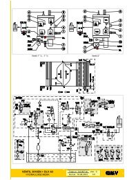
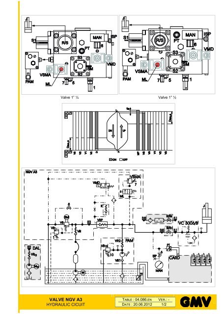
Valve 1” ¼<br />
Valve 1” ½<br />
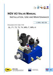
<strong>VALVE</strong> <strong>NGV</strong> <strong>A3</strong><br />
HYDRAULIC CICUIT<br />
TABLE : 04.086.EN VER.: -<br />
DATE : 20.06.2012 1/2
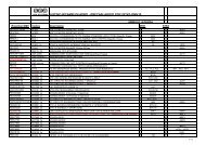
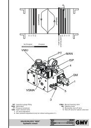
ABBREVIATIONS FOR ALL THE GMV HYDRAULIC SHEMES<br />
1 Adjustment screw : safety valve (pressure P<br />
relief)<br />
VRP pilot spool<br />
2 Adjustment screw : levelling speed PAM Hand pump<br />
3 Adjustment screw : deceleration (upward /<br />
downward)<br />
P max<br />
Maximum pressure limit switch<br />
4 Adjustment screw : acceleration (upward) P min minimum pressure limit switch<br />
5 Shut-off valve / Screw for rupture valve test PT Pressure transducer<br />
6 Shut-off valve for pressure gauge exclusion R/S Ball valve (1)/Silencer (2)<br />
7 Adjustment screw : ram pressure (only 2:1<br />
acting jacks)<br />
RDY Ready - Ready signal (card output to control<br />
panel)<br />
8 Adjustment screw : high speed RIT Delay<br />
9 Adjustment screw : downward speed RO<br />
compensation<br />
Oil heating resistance<br />
10 Adjustment screw : safety valve (PAM) RT Motor thermistors<br />
3010, 3010EN<br />
RUN Run - Start signal (card output to control<br />
Valve 3010 (complete)<br />
panel)<br />
BOX Interface box (Valve / Control panel) S1 (VRP) Sensor to control the VRP closing<br />
C1 Chamber of the VRP S2 (VBC) Sensor to control the VB closing<br />
C2 Inlet chamber S3 (VBO) Sensor to control the VB opening<br />
C3 VB outlet chamber SCC Starting Current Control<br />
C4 Chamber of the VRP pilot spool SM Stepping motor<br />
CARD Control board of the valve TO Oil thermostat<br />
CHG Change TT Temperature transducer<br />
D<br />
UP Upward / Up - command of starting upward<br />
Downward signal<br />
(card to control panel)<br />
DAL Auxiliary levelling device V0 Speed : high<br />
DIR Direct V1 Speed : medium<br />
DLV <strong>A3</strong> DLV <strong>A3</strong> Valve V2 Speed : inspection<br />
DN Downward V3 Speed : fine levelling<br />
FLT Filter VAL Valve (Valve only)<br />
ISP Inspection gauge fitting VB Main flow adjustment valve<br />
J Jack VC Rupture valve<br />
J 1:1 Jack - direct 1:1 VMD Downward solenoid valve<br />
K Non-return valve VML Levelling solenoid valve<br />
M, Ma Motor VMP Starting solenoid valve (Y-D / SCC)<br />
M1 Spool of the VRP VP Pressure valve<br />
MAN Pressure gauge VR Non-return valve (flow outlet)<br />
ML Manual lowering button VR1 Non-return valve (inlet)<br />
MP Motor / pump VR2 Non-return valve (outlet)<br />
MPS Maximum pressure spool VRa Non-return valve (flow outlet) - Auxiliary<br />
<strong>NGV</strong> <strong>NGV</strong> Valve (Complete) VRF Flow regulation valve<br />
<strong>NGV</strong>-<strong>A3</strong> <strong>NGV</strong> <strong>A3</strong> Valve (Complete) VRFP Ausiliary flow regulation valve<br />
OFF Not powered VRP Non-return valve - controlled<br />
OLD, OVL Full load pressure limit switch VS Pilot valve, Upward signal [<strong>NGV</strong>]<br />
ON Powered VS1, VS10 Pressure safety valve<br />
OPP MPS pilot valve VSMA Lowering valve manual / electrical<br />
Y, Δ, Y-Δ Star, Delta, Star-Delta<br />
<strong>VALVE</strong> <strong>NGV</strong> <strong>A3</strong><br />
HYDRAULIC CICUIT<br />
TABLE : 04.086.EN VER.: -<br />
DATE : 20.06.2012 2/2