1 Safety instructions 2 Device components KNX/EIB - Gira
1 Safety instructions 2 Device components KNX/EIB - Gira
1 Safety instructions 2 Device components KNX/EIB - Gira

Create successful ePaper yourself
Turn your PDF publications into a flip-book with our unique Google optimized e-Paper software.
<strong>KNX</strong>/<strong>EIB</strong><br />
Weather station Standard<br />
Weather station Standard<br />
Order-No. : 2150 04<br />
Operating <strong>instructions</strong><br />
1 <strong>Safety</strong> <strong>instructions</strong><br />
Electrical equipment may only be installed and fitted by electrically skilled persons.<br />
Failure to observe the <strong>instructions</strong> may cause damage to the device and result in fire and<br />
other hazards.<br />
Do not operate in the vicinity of chimneys or other exhaust or ventilation systems. Doing<br />
so will compromise function.<br />
Do not operate in the vicinity of radio transmitter systems. Doing so will compromise<br />
function.<br />
Select the mounting place so that the device will still be accessible for maintenance<br />
purposes.<br />
These <strong>instructions</strong> are an integral part of the product, and must remain with the end<br />
customer.<br />
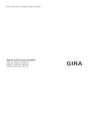
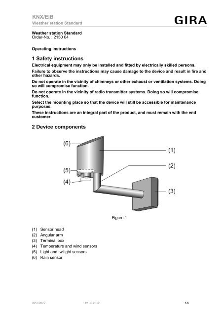
2 <strong>Device</strong> <strong>components</strong><br />
Figure 1<br />
(1) Sensor head<br />
(2) Angular arm<br />
(3) Terminal box<br />
(4) Temperature and wind sensors<br />
(5) Light and twilight sensors<br />
(6) Rain sensor<br />
82562822 12.06.2012<br />
1/6
<strong>KNX</strong>/<strong>EIB</strong><br />
Weather station Standard<br />
3 Function<br />
System information<br />
This device is a product of the <strong>KNX</strong> system and complies with the <strong>KNX</strong> directives. Detailed<br />
technical knowledge obtained in <strong>KNX</strong> training courses is a prerequisite to proper<br />
understanding.<br />
The function of this device depends upon the software. Detailed information on loadable<br />
software and attainable functionality as well as the software itself can be obtained from the<br />
manufacturer´s product database. Planning, installation and commissioning of the device are<br />
carried out with the aid of <strong>KNX</strong>-certified software. The latest versions of product database and<br />
the technical descriptions are available on our website.<br />
Intended use<br />
- Measurement and evaluation of the weather data: Wind speed, Precipitation, Twilight,<br />
Temperature and brightness<br />
- Vertical installation on the outside of buildings, preferable in the roof and facade area<br />
Product characteristics<br />
- Integrated <strong>KNX</strong> bus coupling unit<br />
- Compact housing<br />
- Low-maintenance<br />
- Measurement data acquisition and limit value monitoring<br />
- Integrated heating<br />
4 Information for electrically skilled persons<br />
4.1 Fitting and electrical connection<br />
Fitting the device<br />
DANGER!<br />
Electrical shock when live parts are touched.<br />
Electrical shocks can be fatal.<br />
Before working on the device, disconnect the power supply and cover up live<br />
parts in the working environment.<br />
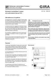
Figure 2<br />
82562822 12.06.2012 2/6
<strong>KNX</strong>/<strong>EIB</strong><br />
Weather station Standard<br />
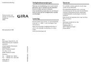
Figure 3<br />
The mounting place must be suitable. The device may not be influenced by obstacles or<br />
shadowing effects on any side.<br />
i Minimum distance to surfaces below the weather station: 0.5 m (Figure 2). Otherwise, the<br />
sensors on the underside may get damaged by penetrating spray water (Figure 3).<br />
i Select the mounting place so that the weather station will still be accessible later for<br />
maintenance purposes.<br />
i Direct sunlight affects the temperature measurement.<br />
i Installation on tubular mast with separate mast fastening (see chapter 5.2. Accessories).<br />
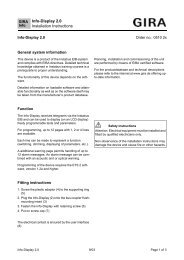
o Open terminal box.<br />
o Route the cables for the power supply and bus connection through one of the two cable<br />
entries (11) and into the terminal box (3).<br />
o Fasten lower part of terminal box e.g. to a building wall, tubular mast.<br />
o Connect supply voltage to connecting terminal (9).<br />
o Connect <strong>KNX</strong> bus line to connecting terminal (10).<br />
i The yellow and white wire wire pair of the <strong>KNX</strong> bus cable can be used to provide an<br />
additional power supply. Observe directives for SELV.<br />
o Connect connecting plug of the sensor head (1) to sensor terminal (8) in terminal box (3).<br />
Figure 4<br />
82562822 12.06.2012 3/6
<strong>KNX</strong>/<strong>EIB</strong><br />
Weather station Standard<br />
CAUTION!<br />
The angular arm (2) may break when the terminal box is closed.<br />
The device can be damaged!<br />
The angular arm must not be used as a lever and pulled downwards.<br />
o Set device on lower part of terminal box from above and snap in at bottom.<br />
Aligning the device<br />
Figure 5<br />
o Orient sensor head using a compass in such a way that the bevelled surface and<br />
brightness sensor 2 (Figure 5) point south.<br />
i Without correct orientation the brightness sensors will not be assigned to the compass<br />
directions. The arrangement of the brightness sensor – seen from above – is shown in<br />
Figure 3.<br />
i In some circumstances it may be advisable to orient the device according to the specific<br />
local conditions, e.g. according to the facades. Geographical features may also necessitate<br />
a different orientation.<br />
Dismantling the device<br />
o Insert screwdriver into the notch on the underside of the terminal box and carefully lever<br />
the device upwards.<br />
o Remove sensor connector from sensor terminal (5).<br />
82562822 12.06.2012 4/6
<strong>KNX</strong>/<strong>EIB</strong><br />
Weather station Standard<br />
4.2 Commissioning<br />
Commissioning the device<br />
Figure 6<br />
o Switch on the bus voltage<br />
o Switch on supply voltage.<br />
o Hold the supplied programming magnet by the integrated reed contact (13).<br />
The programming LED shows the programming state red.<br />
o Assign physical addresses and load application software into the device.<br />
o Note physical address on adhesive labels in terminal box (12) and in cover of the terminal<br />
box (Figure 4).<br />
The device is ready for operation.<br />
5 Appendix<br />
5.1 Technical data<br />
<strong>KNX</strong> medium<br />
TP1<br />
Commissioning mode<br />
S mode<br />
Rated voltage <strong>KNX</strong><br />
DC 21 ... 32 V SELV<br />
Power consumption <strong>KNX</strong><br />
Connection mode <strong>KNX</strong><br />
typical 450 mW<br />
Connection terminal<br />
External supply<br />
Rated voltage<br />
24 V AC/DC SELV<br />
Power consumption<br />
typical 7.5 W<br />
Connection mode<br />
Connecting terminal yellow/white<br />
Ambient conditions<br />
Ambient temperature<br />
-20 ... +55 °C (free of ice and dirt)<br />
Storage/transport temperature -40 ... +70 °C<br />
Housing<br />
Protection rating<br />
IP 44 (in position for use)<br />
<strong>Safety</strong> class<br />
III<br />
Dimensions W × H x D<br />
approx. 88 ×170 ×204 mm (with assembly<br />
arm)<br />
Weight<br />
approx. 240 g<br />
Temperature sensor<br />
Measuring range for temperature<br />
Accuracy<br />
-20 ... +55 °C<br />
± 1 K (for wind speeds > 0.5 m/s)<br />
82562822 12.06.2012 5/6
<strong>KNX</strong>/<strong>EIB</strong><br />
Weather station Standard<br />
Wind sensor<br />
Measuring range for wind<br />
Accuracy<br />
Precipitation sensor<br />
Measuring range for precipitation<br />
Sensitivity to precipitation<br />
Brightness sensors<br />
Compass directions<br />
Spectral range<br />
Measuring range for brightness<br />
Accuracy<br />
Twilight sensor<br />
Direction<br />
Spectral range<br />
Measuring range for twilight<br />
Accuracy<br />
0 ... 40 m/s<br />
2 m/s<br />
Yes/No (binary)<br />
Fine drizzle<br />
east, south, west<br />
700 ... 1050 nm<br />
1 ... 110 klx<br />
10 % (fm. ET)<br />
south<br />
700 ... 1050 nm<br />
0 ... 674 lx<br />
10 % (fm. ET)<br />
5.2 Accessories<br />
Power supply Order-No. 1024 00<br />
Additional power supply Order-No. 2570 00<br />
Mast attachment for installation on freestanding<br />
Order-No. 0848 00<br />
masts<br />
5.3 Warranty<br />
The warranty is provided in accordance with statutory requirements via the specialist trade.<br />
Please submit or send faulty devices postage paid together with an error description to your<br />
responsible salesperson (specialist trade/installation company/electrical specialist trade). They<br />
will forward the devices to the <strong>Gira</strong> Service Center.<br />
<strong>Gira</strong><br />
Giersiepen GmbH & Co. KG<br />
Elektro-Installations-<br />
Systeme<br />
Industriegebiet Mermbach<br />
Dahlienstraße<br />
42477 Radevormwald<br />
Postfach 12 20<br />
42461 Radevormwald<br />
Deutschland<br />
Tel +49(0)21 95 - 602-0<br />
Fax +49(0)21 95 - 602-191<br />
www.gira.de<br />
info@gira.de<br />
82562822 12.06.2012 6/6