You also want an ePaper? Increase the reach of your titles
YUMPU automatically turns print PDFs into web optimized ePapers that Google loves.
PR & OS Owner’s Manual<br />
Patent 6253416<br />
BILLY GOAT POWER RAKE AND OVERSEEDER<br />
PR550, PR550H, PR550T, PR500HT, <strong>OS551</strong>, <strong>OS551</strong>H, PR600S, OS600S<br />
Owner's Manual<br />
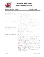
Accessories<br />
SLICING REEL<br />
A complete vertislicing<br />
reel for your<br />
PR. 20" wide reel for<br />
use in grasses that<br />
require vertical<br />
cutting, and for<br />
assisting in lawn<br />
overseeding projects.<br />
P/N 350113<br />
SLICING BLADES<br />
A full set of blades for<br />
replacement. Includes<br />
new lockwashers for<br />
replacement<br />
installation.<br />
P/N 350187<br />
OVERSEEDER KIT<br />
The new light weight Plastic Overseeding<br />
Kit is constructed of durable High Density<br />
Polypropylene with two lift handles on<br />
each side to assist in lifting the entire unit<br />
and easily converts a PR Series Power<br />
Rake into an overseeder with 4 bolts and<br />
minimal tools.<br />
NOTE: Overseeder Conversion Kit<br />
(350328) includes Slicing Reel (350113).<br />
Part No. (350325) comes with the<br />
Overseeder Box only.<br />
P/N 350325 / 350328<br />
Replacement Parts<br />
FLAIL BLADES<br />
A complete set of<br />
our high quality flail<br />
blades for your PR.<br />
Includes new lock<br />
clips for<br />
replacement<br />
installation.<br />
P/N 350186<br />
FLAIL SHAFTS<br />
A full set of shafts<br />
for replacement.<br />
Includes new lock<br />
clips for<br />
replacement<br />
installation.<br />
P/N 350185<br />
Part No 350324<br />
1<br />
Form No F090508B
PR & OS Owner’s Manual<br />
ABOUT THIS MANUAL<br />
THANK YOU for purchasing a BILLY GOAT ® Power Rake/Overseeder. Your new machine has been carefully<br />
designed and manufactured to provide years of reliable and productive service. This manual provides complete<br />
operating and maintenance instructions that will help to maintain your machine in top running order. Read this<br />
manual carefully before assembling, operating, or servicing your equipment.<br />
CONTENTS<br />
SERIAL PLATE DATA AND SPECIFICATIONS 3<br />
GENERAL SAFETY 4 -5<br />
SOUND AND VIBRATION 6<br />
INSTRUCTION LABELS 7<br />
PACKING CHECKLIST & ASSEMBLY 8<br />
OPERATION 9-12<br />
MAINTENANCE 13<br />
TROUBLESHOOTING AND WARRANTY PROCEDURE 14<br />
ILLUSTRATED PARTS LIST 15-18<br />
PARTS LIST 19<br />
MAINTENANCE RECORD 20<br />
Part No 350324<br />
2<br />
Form No F090508B
PR & OS Owner’s Manual<br />
SERIAL PLATE DATA<br />
Record the model number, serial number, date of<br />
purchase, and where purchased.<br />
Purchase Date:<br />
Purchased From:<br />
Specifications<br />
PR550 PR550H <strong>OS551</strong> <strong>OS551</strong>H PR550T PR550HT PR600S OS600S<br />
Engine: HP 5.5 (4.1 kW) 5.5 (4.1 kW) 5.5 (4.1 kW) 5.5 (4.1 kW) 5.5 (4.1 kW) 5.5 (4.1 kW) 6.0 HP (4.7kW) 6.0 HP (4.7kW)<br />
Engine: Model 12H1320118B8 GX160T1QX2 12H1320118B8 GX160T1QX2 12H1320118B8 GX160T1QX2 EX17D50012 EX17D50012<br />
Engine: Type<br />
B&S<br />
VANGUARD<br />
HONDA OHV<br />
B&S<br />
VANGUARD<br />
HONDA OHV<br />
B&S<br />
VANGUARD<br />
HONDA OHV SUBARU SUBARU<br />
Engine: Fuel Capacity 3.0 qt. (2.84 L) 3.88 qt. (3.6 L) 3.0 qt. (2.84 L) 3.88 qt. (3.6 L) 3.0 qt. (2.84 L) 3.88 qt. (3.6 L) 3.8 qt.(3.6 L) 3.8 qt.(3.6 L)<br />
Engine: Oil Capacity 0.66 qt. (0.62 L) 0.69 qt. (0.65 L) 0.66 qt. (0.62 L) 0.69 qt. (0.65 L) 0.66 qt. (0.62 L) 0.69 qt. (0.65 L) 0.63 qt.(0.60 L) 0.63 qt.(0.60 L)<br />
Total Unit Weight: 149# (67.7 kg) 147# (66.8 kg) 162# (73.6 kg) 160# (72.7 kg) 139# (63.2 kg) 137# (62.3 kg) 137# (62.3 kg) 137# (62.3 kg)<br />
Engine weight: 36# (16.3 kg) 34# (15.4 kg) 36# (16.3 kg) 34# (15.4 kg) 36# (16.3 kg) 34# (15.4 kg) 34# (15.4 kg) 34# (15.4 kg)<br />
Max. operating slope 15 o 20 o 15 o 15 o 20 o 20 o 20 o 20 o<br />
Sound test in accordance with<br />
2000/14/EC<br />
101 dB(a) 101 dB(a) 101 dB(a) 101 dB(a) 101 dB(a) 101 dB(a) 101 dB(a) 101 dB(a)<br />
Sound at operators ear 82 dB(a) 82 dB(a) 82 dB(a) 82 dB(a) 82 dB(a) 82 dB(a) 82 dB(a) 82 dB(a)<br />
Vibration at operator position 0.82g (8.04 m/s 2 ) 0.82g (8.04<br />
m/s 2 )<br />
3.2g 3.2g 3.2g 3.2g 3.2g 3.2g<br />
Part No 350324<br />
3<br />
Form No F090508B
PR & OS Owner’s Manual<br />
GENERAL SAFETY INSTRUCTIONS and SYMBOLS<br />
The safety symbols shown below are used throughout this manual. You should become familiar with them before<br />
assembling, operating, or servicing this equipment.<br />
This symbol indicates important information that will prevent injury to yourself or others.<br />
This symbol indicates ear protection is recommended when operating this equipment.<br />
This symbol indicates eye protection is recommended when operating this equipment.<br />
This symbol indicates gloves should be worn when servicing this equipment.<br />
This symbol indicates that this manual and the engine manufacturer’s manual should be read<br />
carefully before assembling, operation, or servicing this equipment.<br />
This symbol indicates important information that will prevent damage to your BILLY GOAT ®<br />
Power Rake/Overseeder.<br />
This symbol indicates the engine oil level should be checked before operating this<br />
equipment.<br />
Read and make sure you thoroughly understand the following safety precautions before assembling, operating or<br />
servicing this equipment:<br />
READ this manual and the engine manufacturer’s manual carefully before assembling,<br />
operating, or servicing this equipment.<br />
EAR PROTECTION is recommended when operating this equipment.<br />
EYE PROTECTION is recommended when operating this equipment.<br />
BREATHING PROTECTION is recommended when operating this equipment.<br />
EXHAUST from this product contains chemicals known to the State of California to cause<br />
cancer, birth defects or other reproductive harm.<br />
DO NOT operate this equipment on any unimproved forested, brushy, or grass covered land<br />
unless a spark arrester is installed on the muffler as required by Section 4442 of the<br />
California Public Resources Code. The arrester must be maintained in good working order.<br />
Other states may have similar laws. Federal laws apply on federal lands.<br />
DO NOT run engine in an enclosed area. Exhaust gases contain carbon monoxide, an<br />
odorless and possibly fatal poison.<br />
Part No 350324<br />
4<br />
Form No F090508B
PR & OS Owner’s Manual<br />
DO NOT run this equipment indoors or in any poorly ventilated area. Refueling outdoors is<br />
recommended.<br />
DO NOT refuel this equipment while the engine is running. Allow engine to cool for at least<br />
two minutes before refueling.<br />
DO NOT store gasoline near an open flame.<br />
DO NOT remove gas cap while engine is running.<br />
DO NOT start or operate engine if strong odor of gasoline is present.<br />
DO NOT start or operate engine if gasoline is spilled. Move equipment away from spill until<br />
gasoline has completely evaporated.<br />
DO NOT smoke while filling the fuel tank.<br />
DO NOT check for spark with spark plug or spark plug wire removed. Use an approved spark<br />
tester.<br />
DO NOT operate engine without a muffler. Inspect muffler periodically and replace if<br />
necessary. If equipped with muffler deflector, inspect deflector periodically and replace if<br />
necessary.<br />
DO NOT operate engine with grass, leaves or other combustible material near the muffler.<br />
DO NOT touch muffler, cylinder, or cooling fins when hot. Contact with hot surfaces may<br />
cause severe burns.<br />
DO NOT leave equipment unattended while in operation.<br />
DO NOT park equipment on a steep grade or slope.<br />
DO NOT operate equipment with bystanders in or near the work area.<br />
DO NOT allow children to operate this equipment.<br />
DO NOT operate equipment with guards removed.<br />
DO NOT operate equipment near hot or burning debris or any toxic or explosive materials.<br />
DO NOT operate equipment on slopes greater than specified in Specifications section of this<br />
manual.<br />
DO NOT start engine without height adjust lever in up position and clutch bail disengaged.<br />
DO NOT place hands or feet underneath unit, or near any moving parts.<br />
ALWAYS remove spark plug wire when servicing equipment to prevent accidental starting.<br />
ALWAYS check fuel lines and fittings frequently for cracks or leaks. Replace if necessary.<br />
ALWAYS keep hands and feet away from moving or rotating parts.<br />
ALWAYS store fuel in approved safety containers.<br />
WARNING: Important<br />
Remove all rocks, wire, string, etc. that can present a hazard during work prior to starting.<br />
DO identify and mark all fixed objects to be avoided during work such as sprinkler heads,<br />
water valves, buried cables, or clothes line anchors, etc.<br />
Part No 350324<br />
5<br />
Form No F090508B
PR & OS Owner’s Manual<br />
SOUND<br />
SOUND LEVEL 82 dB(a) at Operators Position<br />
Sound tests were conducted in accordance with 2000/14/EC, and were performed on 2-13-2002 under the<br />
conditions listed below.<br />
Sound power level listed is the highest value for any model covered in this manual. Please refer to serial plate on<br />
the unit for the sound power level for your model.<br />
General Conditions:<br />
Sunny<br />
Temperature: 48 o F (8.9 o C)<br />
Wind Speed:<br />
2 mph (3.2 kmh)<br />
Wind Direction:<br />
South East<br />
Humidity: 29%<br />
Barometric Pressure:<br />
30.34Hg (770 mm Hg)<br />
VIBRATION DATA<br />
VIBRATION LEVEL .82g (8.04m/s 2 )<br />
Vibration levels at the operator’s handles were measured in the vertical, lateral and longitudinal directions using<br />
calibrated vibration test equipment. Tests were performed on 5-25-2006 under the conditions listed below.<br />
General Conditions:<br />
Sunny<br />
Temperature: 72.32 o F (22.4 o C)<br />
Wind Speed:<br />
3.8 mph (6.12kph)<br />
Wind Direction:<br />
East<br />
Humidity: 62.2%<br />
Barometric Pressure:<br />
29.9Hg (101.3kpa)<br />
INTENDED USE<br />
INTENDED USE: This machine is designed for removing thatch from your lawn, renovation of existing lawns, and to<br />
assist in overseeding operations. The machine should not be used for any other purpose than that stated above.<br />
Do not operate if excessive vibration occurs. If excessive vibration occurs, shut engine off immediately and check<br />
for damaged or worn reel, loose pulley bolts or set screws, loose engine or lodged foreign objects. (See trouble<br />
shooting section on page 14).<br />
Part No 350324<br />
6<br />
Form No F090508B
PR & OS Owner’s Manual<br />
INSTRUCTION LABELS<br />
The labels shown below were installed on your BILLY GOAT ® Power Rake/Overseeder. If any labels are damaged or missing, replace them<br />
before operating this equipment. Item numbers from the Illustrated Parts List and part numbers are provided for convenience in ordering<br />
replacement labels. The correct position for each label may be determined by referring to the Figure and Item numbers shown.<br />
LABEL DANGER KEEP HANDS LABEL CLUTCH ITEM #49 DANGER FLYING DEBRIS<br />
AND FEET AWAY P/N 830503 ITEM # 48 P/N 810736<br />
ITEM #51 P/N 400424<br />
LABEL CAUTION GUARDS LABEL EXPLOSIVE FUEL LABEL INSTRUCTION HEIGHT ADJ.<br />
ITEM #52 P/N 900327 ITEM # 50 P/N 400268 ITEM #35 P/N 350176<br />
LABEL INSTRUCTIONS SEEDER BOX<br />
ITEM #45 P/N 350288<br />
ENGINE LABELS<br />
BRIGGS & STRATTON<br />
HONDA<br />
OIL ALERT<br />
WHEN OIL LEVELLOW,<br />
ENGINE STOPS IMMEDIATELY.<br />
ENGINE CONTROLS<br />
Honda Briggs & Stratton Set lever to choke when starting cold<br />
Throttle lever<br />
Set lever to desired engine speed.<br />
Fuel valve Choke lever Move lever completely to the left to<br />
stop engine<br />
Part No 350324<br />
7<br />
Form No F090508B
PR & OS Owner’s Manual<br />
PACKING CHECKLIST<br />
Your <strong>Billy</strong> <strong>Goat</strong> Power Rake is shipped from the factory in one carton, completely assembled.<br />
READ all safety instructions before assembling unit.<br />
TAKE CAUTION when removing the unit from the box the Handle Assembly is attached to the<br />
unit by cables.<br />
PUT OIL IN ENGINE BEFORE STARTING<br />
PARTS BAG &<br />
LITERATURE ASSY<br />
Warranty card P/N- 400972, Owner’s Manual P/N-350324, Declaration of Conformity P/N-350139.<br />
26<br />
28<br />
Boxing Parts<br />
Checklist<br />
Briggs & Stratton<br />
5.5 B&S VANGUARD<br />
28<br />
28<br />
Honda 5.5 OHV<br />
Subaru 6HP EX17<br />
Literature Assy<br />
P/N-430334<br />
PR550, PR550H,<br />
PR550T, PR550HT,<br />
PR600S<br />
<strong>OS551</strong>, <strong>OS551</strong>H,<br />
and OS600S<br />
ASSEMBLY<br />
1. UNFOLD the upper handle (item 26) and slide handle lock loops (item 28) into place to secure the upper handle<br />
to the lower.<br />
2. CHECK engine oil level and fill to proper level with engine manufacturers recommended grade of oil. Move<br />
height adjust lever to down position, to level engine during checking. See engine manufacturers instruction<br />
manual.<br />
3. CONNECT spark plug wire.<br />
Part No 350324<br />
8<br />
Form No F090508B
PR & OS Owner’s Manual<br />
OPERATION<br />
Like all mechanical tools, reasonable care must be used when operating machine.<br />
Inspect machine work area and machine before operating. Make sure that all operators of this<br />
equipment are trained in general machine use and safety.<br />
PUT OIL IN ENGINE BEFORE STARTING<br />
STARTING<br />
ENGINE: See engine manufacturer’s instructions for type and amount of oil and gasoline used. Engine must be<br />
level when checking and filling oil and gasoline.<br />
FUEL VALVE: Move fuel valve to "ON" position (when provided on engine).<br />
STOP SWITCH: Located on the engine. "ON" position.<br />
CHOKE: Operated with choke lever on side of engine.<br />
THROTTLE: Controlled by throttle lever on the motor.<br />
IF YOUR UNIT FAILS TO START:<br />
See Troubleshooting on page 14.<br />
FOLDING HANDLE<br />
This unit is equipped with a folding upper handle for easier storage and transportation. The handle can be folded by<br />
sliding the handle lock loops (item 28) up. This releases the upper handle, allowing it to be folded over the unit.<br />
HANDLING & TRANSPORTING:<br />
This unit requires two people to lift it. With the handle in the folded position, lift holding the lower handle and<br />
belt/shaft guard one on each side of the machine. Secure the machine in place during transport. See page 3 for<br />
weight specifications<br />
Never lift the machine while the engine is running.<br />
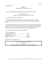
ADJUSTING BLADE DEPTH<br />
The depth of the blades can be raised or lowered by rotating the knob on the<br />
top of the adjustment lever. The blades are lowered by rotating the knob<br />
clockwise, and raised by rotating the knob counter-clockwise. The relative<br />
depth of the blades can be gauged by using the depth scale located on the<br />
right front corner of the engine base. With new blades installed the depth can<br />
be estimated as follows: 2.5 on the scale is even with the ground, 3 is equal<br />
to 0.25" deep, and 3.5 is equal to 0.5" deep<br />
BLADE POSITION & DEPTH CONTROL LEVER<br />
The blades can be raised or lowered into the ground by height adjustment lever<br />
on the engine base. The height adjuster lock lever must be pushed back against<br />
the adjustment lever in order to lower the blades into the ground. The resulting<br />
blade depth can be adjusted higher or lower.<br />
See ADJUSTING BLADE DEPTH.<br />
SPRING TINE CONVERSION<br />
If are converting your Power rake to a spring tine reel, you will need<br />
to replace the spacer on the control lever to accommodate for the<br />
tine. First remove the clip (item 18), then unscrew the yoke (item<br />
17), remove the washer (items 69) and insert the spacer (item 75) in<br />
front of the spring. Reassemble in reverse order.<br />
clockwise to<br />
lower blades<br />
blades up<br />
transport<br />
blades down<br />
running<br />
counter clockwise<br />
to raise blades<br />
blades up<br />
transport<br />
Part No 350324<br />
9<br />
Form No F090508B
PR & OS Owner’s Manual<br />
RAKING/SLICING TIPS<br />
Before beginning, it is best to evaluate the condition of the lawn by cutting one or more core<br />
samples from area to be treated. A core can be cut using a piece of pvc, or metal pipe.<br />
Hammer the pipe into the ground, remove it, push the core out of the pipe and inspect it to<br />
determine the depth of thatch in your yard.<br />
THATCH: Thatch is a dense layer of dead grass, clippings, and roots that builds up over time<br />
at the base of of the lawn preventing air, water, and fertilizer from reaching the soil. This can<br />
cause shallow root development and make a lawn more susceptible to drought and disease.<br />
Thatch also provides an ideal environment for insects to hide and multiply. Periodic removal of<br />
thatch will keep your lawn in good health.<br />
HEAVY THATCH: Lawns with an excessive amount of thatch will require multiple treatments<br />
for effective removal. Trying to remove excessive thatch (greater than 3/4"[19 mm] deep) in<br />
one treatment will damage or destroy the living part of the lawn. It is best to remove heavy<br />
thatch in seasonal treatments (i.e. spring, and fall).<br />
SLOPES: Rake slopes across not up and down. This is much easier and safer for the<br />
operator and is better for the lawn. Raking across will help to reduce runoff during watering<br />
and allow the sloped ground to hold more seed, fertilizer, and water. The units maximum<br />
operating slope is 35% or 19°.<br />
DEPTH: The wide range of depth adjustment on your unit is provided to allow for blade wear.<br />
Setting the reel deeper will not produce better, or quicker results. The flail reel is intended to<br />
be set so it just touches the surface on flat ground. The slicing reel should be set even with the<br />
ground for verti-slicing work, and set to a maximum 1/2" depth for overseeding jobs. Setting<br />
the reel deeper than this will only result in premature wear on the unit (i.e. failed belt). If you<br />
desire to work the ground deeper than the above guidelines allow, it should be done gradually<br />
in multiple passes..<br />
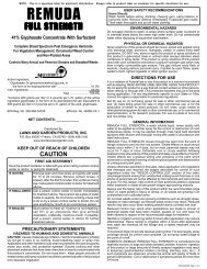
SLICING / OVERSEEDING: Mow the lawn to shorter than the normal cut height before<br />
starting (i.e. approximately 2" tall for fescue grass). For the best result, Slice/Overseed in crisscross<br />
pattern (See Fig. 1 and See Fig 2).<br />
Fig. 1<br />
Fig. 2<br />
RAKING OPERATION-FLAIL REEL<br />
NOTE: Must have the flail reel assembly (350112) for this operation.<br />
MOW: Mow the lawn to it's normal cut height.<br />
DRY: Be sure grass is dry. Wet conditions can cause increased damage to healthy grass.<br />
SET DEPTH: With engine off, set the raking depth so that the blades just touch on a flat<br />
surface (i.e. driveway, or sidewalk).<br />
START ENGINE: See page 9 for further instruction.<br />
ENGAGE BLADES: Pull back on the bail on the operators handle. NOTE: When engaging the<br />
blades in heavy load conditions (i.e. heavy thatch, or very uneven turf), push down on the<br />
operators handle lifting the front wheels slightly. Engage the blades. Slowly lower the unit into<br />
the turf.<br />
RAKE: Rake a small test area and examine the results. Thatch should be removed and<br />
deposited on top of the healthy grass. If excessive damage occurs to healthy grass, adjust the<br />
blade depth to decrease damage. Continue raking the yard, working in one direction (i.e.<br />
north-south, or east-west). NOTE: If a large drop in engine RPM occurs, or the unit pulls you<br />
forward and bounces during operation the blade depth is set too low.<br />
REMOVE THATCH: After raking, a layer of thatch will be deposited over the top of the lawn.<br />
This thatch must be removed prior to any fertilizing, seeding, or watering of the lawn. We<br />
suggest the use of a lawn vacuum or wheeled blower for collection and removal of the thatch.<br />
Part No 350324<br />
10<br />
Form No F090508B
PR & OS Owner’s Manual<br />
RAKING OPERATION-SPRING REEL<br />
NOTE: Must have the spring tine reel assembly (350354) for this operation.<br />
MOW: Mow the lawn to it’s normal cut height. Tall grass will not leave a manicured look when the<br />
dethatching job is complete.<br />
DRY: Be sure grass is relatively dry. Wet conditions can cause increased damage to healthy grass.<br />
SET DEPTH: With engine off, set the raking depth so that the spring tines are just above touching the<br />
flat surface (i.e. driveway, or sidewalk) the units height is being adjusted on. NOTE: Allowing the<br />
spring tines to have substantial contact with the ground will cause premature wear and failure of the<br />
spring tines.<br />
START ENGINE: See page 9 for further instruction.<br />
ENGAGE TINES: Pull back on the bail on the operators handle. NOTE: When engaging the spring<br />
tines in heavy load conditions (i.e. heavy thatch, or very uneven turf), push down on the operators<br />
handle lifting the front wheels slightly. Engage the spring tines. Slowly lower the unit into the turf.<br />
RAKE: Rake a small test area and examine the results. Thatch should be removed and deposited on<br />
top of the healthy grass. If excessive damage occurs to healthy grass, adjust the spring tine depth to<br />
decrease damage. Continue raking the yard, working in one direction (i.e. north-south, or east-west).<br />
NOTE: If a large drop in engine RPM occurs, or the unit pulls you forward and bounces during<br />
operation the spring tine depth is set too low.<br />
REMOVE THATCH: After raking, a layer of thatch will be deposited over the top of the lawn. This<br />
thatch must be removed prior to any fertilizing, seeding, or watering of the lawn. We suggest the use<br />
of a lawn vacuum or wheeled blower for collection and removal of the thatch.<br />
VERTI-CUTTING OPERATION<br />
NOTE: Must have the slicing reel assembly (350113) for this operation.<br />
MOW: Mow the lawn to shorter than the normal cut height (approximately 2" tall)<br />
DRY: Be sure grass is dry. Wet conditions can cause increased damage to healthy grass.<br />
SET DEPTH: With engine off, set the raking depth so that the blades just touch on a flat surface<br />
(i.e. driveway, or sidewalk).<br />
START ENGINE: See Page 9.<br />
ENGAGE BLADES: Pull back on the bail on the operators handle. NOTE: When engaging the<br />
blades in heavy load conditions (i.e. heavy thatch, or very uneven turf), push down on the<br />
operators handle lifting the front wheels slightly. Engage the blades. Slowly lower the unit into the<br />
turf.<br />
SLICE: Verti-cut a small test area and examine the results. Some thatch and cut stems should<br />
be removed and deposited on top of the healthy grass. Grass runners should be cut and ready<br />
for removal. If excessive damage occurs to healthy grass, adjust the blade depth to decrease<br />
damage. Continue raking the yard, working in one direction (i.e. north-south, or east-west).<br />
NOTE: If a large drop in engine RPM occurs, or the unit pulls you forward and bounces during<br />
operation the blade depth is set too low.<br />
REMOVE THATCH/STEMS: After verti-cutting, a layer of thatch and cut stems will be deposited<br />
over the top of the lawn. We suggest the use of a lawn vacuum or wheeled blower for collection<br />
and removal of the thatch/stems.<br />
OVERSEEDING OPERATION<br />
NOTE: Must have the slicing reel assembly (350113) for this operation.<br />
MOW: Mow the lawn to shorter than the normal cut height (approximately 2" tall)<br />
DRY: Be sure grass is dry. Wet conditions can cause increased damage to healthy grass.<br />
SEED: Spread grass seed according to the seed suppliers directions (e.g. 10 lbs. per 1000 ft 2 [4.5<br />
kg. per 93 m 2 ])<br />
SET DEPTH: With engine off, set the raking depth so that the blades reach 1/4"-1/2"(6-12 mm)<br />
below a flat surface (i.e. driveway, or sidewalk).<br />
START ENGINE: See Page 9.<br />
ENGAGE CLUTCH: Pull back on the bail on the operators handle. NOTE: When engaging the<br />
clutch in heavy load conditions (i.e. heavy thatch, or very uneven turf), push down on the operators<br />
handle lifting the front wheels slightly. Engage the clutch. Slowly lower the unit into the turf.<br />
SLICE: Run machine over the area that has been seeded to incorporate the seed into the soil. If<br />
excessive damage occurs to healthy grass, adjust the blade depth to decrease damage. Continue<br />
raking the yard, working in one direction (i.e. north-south, or east-west). NOTE: If a large drop in<br />
engine RPM occurs, or the unit pulls you forward and bounces during operation the blade depth is<br />
set too low.<br />
WATER/FERTILIZE: After the seed has been worked into the soil, water and fertilize according to<br />
the seed suppliers directions.<br />
Part No 350324<br />
11<br />
Form No F090508B
PR & OS Owner’s Manual<br />
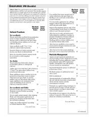
ADJUSTING SEED RATE<br />
DROPPING SEEDS<br />
STOP<br />
SETTING<br />
BRACKET<br />
KNOB<br />
- PULL BACK ON THE KNOB THEN<br />
SLIDE THE BRACKET TO DESIRED<br />
STOP SETTING.<br />
EXAMPLE: STOP SETTING IS ON 4<br />
- IF SLICING WITHOUT DROPPING<br />
SEEDS FOR LONG PERIOD THEN<br />
SET THE STOP SETTING TO ZERO.<br />
LAWN PREPARATION<br />
- MOW LAWN TO LOWEST SETTING ON<br />
YOUR MOWER.<br />
- DO NOT WATER PRIOR TO SEEDING.<br />
- POWER RAKE TO DETHATCH LAWN<br />
AND REMOVE THATCH.<br />
- FERTILIZE LAWN WITH BROADCAST<br />
SPREADER.<br />
- AFTER ADJUSTING THE STOP SETTING, LIFT<br />
UP ON THE BAR TO OPEN THE DROP SEEDER<br />
DOOR.<br />
LAWN PREPARATION<br />
- FOR BEST RESULTS OVERSEED IN<br />
TWO PASSES OF ONE-HALF<br />
APPLICATION RATE EACH, AT RIGHT<br />
ANGLES OR IN A CRISS-CROSS<br />
PATTERN.<br />
- WATER HEAVILY IMMEDIATELY THEN<br />
LIGHTLY FOR 10 - 14 DAYS, KEEPING<br />
SOIL MOIST.<br />
- AFTER GERMINATION, WATER LESS<br />
OFTEN TO PROMOTE ROOT GROWTH.<br />
- TO STOP DROPPING SEEDS, PUSH FORWARD<br />
ON THE HANDLE TO CLOSE THE DROP SEEDER<br />
DOOR.<br />
NOTE: IF SLICING WITHOUT DROPPING SEEDS<br />
FOR LONG PERIOD OF TIME THEN SET THE<br />
STOP SETTING TO ZERO.<br />
SEED APPLICATION CHART:<br />
THESE SETTINGS ARE APPROXIMATE GUIDELINES. SEEDING RATES ARE SPEED DEPENDENT.<br />
FASTER TRAVEL DELIVERS LESS SEED.<br />
SEED<br />
TYPE<br />
RYEGRASS<br />
BLUEGRASS<br />
RATE<br />
LBS<br />
1,000 FT2<br />
1/2<br />
3/4<br />
1 1/2<br />
2 1/3<br />
3/4<br />
STOP<br />
SETTING<br />
1<br />
2<br />
3<br />
4<br />
3<br />
SEED<br />
RATE STOP<br />
TYPE<br />
LBS<br />
SETTING<br />
1,000 FT 2<br />
BENTGRASS<br />
2/3<br />
1<br />
1 1/3<br />
2<br />
BERMUDAGRASS 3/4<br />
1<br />
(HULLED & ZOYSIA) 1 2/3 2<br />
REFERENCE<br />
CHART<br />
BILLY<br />
GOAT<br />
SEEDER<br />
SETTING<br />
SCOTTS<br />
SEEDER<br />
SETTING<br />
(ALL DRO P<br />
SEEDER<br />
MODELS)<br />
FESCUE<br />
1<br />
1 1/2<br />
2 1/2<br />
3/4<br />
1 1/4<br />
2<br />
3 1/2<br />
4<br />
5<br />
6<br />
5<br />
6<br />
7<br />
8<br />
CENTIPEDEGRASS<br />
(CO ATED)<br />
ST. AUGUSTINE<br />
GRASS<br />
2/3<br />
1 1/4<br />
2 1/2<br />
3/4<br />
1<br />
1 1/3<br />
1 1/2<br />
1<br />
2<br />
3<br />
3<br />
4<br />
5<br />
6<br />
5<br />
6<br />
7<br />
8<br />
9<br />
6 1/3<br />
8<br />
10<br />
15 1/2<br />
17<br />
Part No 350324<br />
12<br />
Form No F090508B
PR & OS Owner’s Manual<br />
MAINTENANCE<br />
PERIODIC MAINTENANCE<br />
Periodic maintenance should be performed at the following intervals:<br />
Maintenance Operation Every Use (daily) Every 25 Hours<br />
Inspect for loose, worn or damaged parts.<br />
Check engine oil<br />
Inspect belt<br />
Engine (See Engine Manual)<br />
Grease reel bearings<br />
Inspect and clean engine air filter<br />
Oil height adjustment linkage<br />
•<br />
•<br />
FLAIL BLADE WEAR<br />
1. Wait for engine to cool and disconnect spark plug.<br />
2. Close fuel valve on engine (if available).<br />
3. Lean unit back onto lower handles and secure in place.<br />
4. Inspect blades for wear, and immediately replace any bent or cracked blades. Measure the<br />
overall length of the blade. (See fig. 1)<br />
5. If blades measure less than 3.25"(83 mm) in overall length they must be replaced. NOTE: We<br />
recommend replacing all the flails at once.<br />
•<br />
•<br />
•<br />
•<br />
SLICING BLADE WEAR<br />
1. Wait for engine to cool and disconnect spark plug.<br />
2. Close fuel valve on engine (if available).<br />
3. Lean unit back onto lower handles and secure in place.<br />
4. Inspect blades for wear, and immediately replace any bent or cracked blades. Measure<br />
the overall length of the blade from the center of the attachment bolt to the tip of the worn<br />
blade.<br />
5. If blades measure less than 3"(76 mm) in length they must be replaced. NOTE: We<br />
recommend replacing all the blades at once.<br />
Fig. 1<br />
ROTATING FLAIL REEL END TO END<br />
To maximize flail blade life and performance the reel can be rotated end to end periodically to provide a fresh lead cutting edge. Takes approx. 20 min.<br />
and requires 1/2" and 9/16" socket wrenches with extension bar.<br />
1. Wait for engine to cool and disconnect spark plug.<br />
2. Close fuel valve on engine (if available).<br />
3. Lean unit back onto lower handles and secure in place.<br />
4. Remove (7) lock nuts (item 62 & 40) holding the belt and shaft guards (item 21 & 22) in place. It is necessary to lower the height adjust lever to reach<br />
the locknuts on the guards. Remove the guards.<br />
5. Remove the drive belt (item 9) by "walking" it out of the groove on the reel pulley (item 2).<br />
6. Remove the (4) lock nuts (item 60) and washers (item 68) holding the bearings (item 23) to the frame of the unit.<br />
7. The reel is now free from the machine. Slide the reel down and out of the machine.<br />
8. Remove the capscrew (item 71), lockwasher (item 57), reel pulley (item 2), key (item 42), and reel spacer (item 10) from the end of the reel.<br />
9. Rotate the reel end to end, and re-install these items on the opposite end of the reel.<br />
10. Re-install the reel in reverse order of removal. Re-install the guards in reverse order of removal.<br />
DRIVE BELT REPLACEMENT<br />
NOTE: Takes approx. 10 min. and requires 1/2" socket wrench with extension.<br />
1. Wait for engine to cool and disconnect spark plug.<br />
2. Remove (4) lock nuts (item 62) holding the belt guard (item 21) in place. It is necessary to lower the height adjust lever to reach the locknuts on the<br />
guard. Remove the guard.<br />
3. Remove the belt (item 9) by rotating the reel pulley (item 2) and walking it out of the groove. Discard old belt<br />
4. Install new belt using same procedure to walk the belt into the groove.<br />
5. With new belt installed pull bail rod back to engaged position and measure extension of idler spring. Spring should stretch 3/4" - 1" (19 25 mm) with<br />
bail engaged. Adjust clutch cable as necessary to achieve this extension.<br />
6. Re-install the belt guard.<br />
Part No 350324<br />
13<br />
Form No F090508B
STORAGE<br />
PR & OS Owner’s Manual<br />
Never store engine indoors or in enclosed poorly ventilated areas with fuel in tank, where fuel fumes may reach an open<br />
flame, spark or pilot light, as on a furnace, water heater, clothes dryer or other gas appliance.<br />
If engine is to be unused for 30 days or more, prepare as follows:<br />
Remove all gasoline from carburetor and fuel tank to prevent gum deposits from forming on these parts and causing possible<br />
malfunction of engine. Drain fuel outdoors, into an approved container, away from open flame. Be sure engine is cool. Do not<br />
smoke. Run engine until fuel tank is empty and engine runs out of gasoline.<br />
Troubleshooting<br />
Problem Possible Cause Solution<br />
Abnormal vibration.<br />
· Damaged or missing blades. Loose<br />
handle bolts. Loose engine bolts<br />
· Stop work immediately. Replace any<br />
damaged or missing blades. Tighten all<br />
loose nuts and bolts.<br />
Engine stalls or labors when<br />
raking<br />
Engine will not start.<br />
· Blades set too deep into ground. · Raise blades so that they just touch the<br />
ground on a level surface<br />
· Stop switch off (Honda only). Throttle · Check choke position.<br />
in off position<br />
· Out of gasoline or bad, old gasoline. · Check gasoline.<br />
Engine is locked, will not pull<br />
over.<br />
· Spark Plug wire disconnected. · Connect spark plug wire.<br />
· Gas valve off. · Turn on gas valve.<br />
· Dirty air cleaner. · Clean or replace air cleaner. Contact a<br />
qualified service person.<br />
· Debris locked against reel, or drive<br />
pulleys. Engine problem.<br />
· Pull spark plug wire and remove debris.<br />
Contact an engine servicing dealer for<br />
engine problems.<br />
When servicing engine refer to specific manufacturers engine owner's manual. Engine warranty is covered by the<br />
specific engine manufacturer. If your engine requires warranty or other repair work contact your local servicing<br />
engine dealer. When contacting a dealer for service it is a good idea to have your engine model number available<br />
for reference (See table page 3). If you cannot locate a servicing dealer in your area you can contact the<br />
manufacturers national service organization.<br />
To reach:<br />
American Honda: 800-426-7701<br />
WARRANTY CLAIM PROCEDURE<br />
Should a BILLY GOAT ® machine fail due to a defect in material and/or workmanship, the owner should make a<br />
warranty claim as follows:<br />
• The machine must be taken to the dealer from whom it was purchased or to an authorized Servicing BILLY<br />
GOAT Dealer.<br />
• The owner must present the remaining half of the Warranty Registration Card, or, if this is not available, the<br />
invoice or receipt.<br />
• The Warranty Claim will be completed by the authorized BILLY GOAT Dealer and submitted to their<br />
respective BILLY GOAT Distributor for their territory Attention: Service Manager. Any parts replaced under<br />
warranty must be tagged and retained for 90 days. The model number and serial number of the unit must<br />
be stated in the Warranty Claim.<br />
• The distributor service manager will sign off on the claim and submit it to BILLY GOAT for consideration.<br />
• The Technical Service Department at BILLY GOAT will study the claim and may request parts to be<br />
returned for examination. BILLY GOAT will notify their conclusions to the distributor service manager from<br />
whom the claim was received.<br />
• The decision by the Technical Service Department at BILLY GOAT to approve or reject a Warranty Claim is<br />
final and binding.<br />
For online product registration go to www.billygoat.com<br />
Part No 350324<br />
14<br />
Form No F090508B
PR & OS Owner’s Manual<br />
POWER RAKE SEEDER BOX KIT P/N 350325<br />
PARTS LIST<br />
ITEM NO. PART NO. DESCRIPTION QTY<br />
1 350366 BOX AND LID ASSEMBLY 1<br />
2 350306 BRACKET ADJ DROP SEEDER ASSY 1<br />
3 350276 BAR DOOR LINKAGE 1<br />
4 350320 SHAFT PLASTIC DROP SEEDER 1<br />
5 350271 PLATE DOOR DROP SEEDER 1<br />
6 350272 PLATE DOOR DROP SEEDER END 1<br />
7 350273 PLATE DOOR DROP SEEDER ARM 1<br />
9 350370 PULLEY 3V GROOVE 0.625" BORE 1<br />
10 8171003 WASHER 5/16 FLAT CUT 1<br />
11 900321 BEARING CLIP 1.375 OD 4<br />
12<br />
13 400217 SPRING TENSION 2<br />
14 8024040 BOLT CARRIAGE 5/16 - 18 X 1 1<br />
15 8024021 BOLT CARRIAGE 1/4-20 X 3/4" 1<br />
16 8123087 SCREW SELF TAP #10-24 X 3/8" HMS ZP 4<br />
17 8160001 NUT LOCK 1/4 1<br />
18 350332 BRACKET SLOT PLASTIC SEEDER BOX 1<br />
19 8160002 NUT LOCK 5/16 1<br />
21 350369 PULLEY 3V GROOVE 1.530" BORE 1<br />
22 350280 WASHER 0.906 O.D. X 0.656 I.D. X 0.062 7-8<br />
24 350372 BELT O-RING 5/16 X 15 9/16" 1<br />
25 8197031 PIN COTTER 1/8" X 1" 1<br />
26 9195106 ROLL PIN 1/8 - 1 1/4 1<br />
28 8172007 WASHER 1/4 SAE 1<br />
29 8154007 NUT HEX 10-24 2<br />
30 8059136 SCREWCAP #10-24 X 3/4 2<br />
32 350288 LABEL INSTRUCTION SEEDER BOX 1<br />
33 890456 LABEL HOSE PLUG KD/SV 1<br />
34 350313 LABEL PRODUCT DECAL OS 1<br />
PARTS BAG SEEDER BOX KIT 350326<br />
19 8160002 NUT LOCK 5/16 (REQUIRE ON THE OLD MODELS ONLY) 4<br />
20 8177011 WASHER LOCK 5/16 4<br />
23 8041026 SCREWCAP 5/16-18 x 3/4 4<br />
27 8172020 WASHER 5/16 FENDER 4<br />
31 900230 WASHER 1/2 FC 1-2<br />
32 8161044 NUT LOCK 1/2" THIN HGT 1<br />
- 350327 LIT SEEDER BOX (INCLUDES TEMPLATE) 1<br />
Part No 350324<br />
15<br />
Form No F090508B
PR & OS Owner’s Manual<br />
PARTS DRAWING<br />
FLAIL REEL KIT 350112<br />
item PARTS QTY<br />
no. LIST Part No.<br />
57 LOCK WASHER TWISTED TOOTH 400502 1<br />
71 SCREWCAP REEL PULLEY 8041050 1<br />
73 SHAFT FLAIL BLADE 350141 4<br />
74 BLADE FLAIL 350100 30<br />
76 SPACER BUMPER 5/8" x 1/2" 350144 54<br />
77 SHAFT WA FLAIL REEL 350145 1<br />
78 CLIP LOCK 1/2" 350146 8<br />
79 WASHER 1/2 SAE 8172011 8<br />
FLAIL SHAFT KIT 350185 FLAIL BLADE KIT 350186<br />
item PARTS Part No. QTY<br />
no. LIST<br />
73 SHAFT FLAIL BLADE 350141 4<br />
78 CLIP LOCK 1/2" 350146 8<br />
item PARTS Part No. QTY<br />
no. LIST<br />
74 BLADE FLAIL 350100 60<br />
78 CLIP LOCK 1/2" 350146 8<br />
SPACER BUMPER KIT 350258 SLICING BLADE KIT 350187<br />
item PARTS QTY<br />
no. LIST Part No.<br />
76 SPACER BUMPER 5/8" x 1/2" 350144 54<br />
Part No 350324<br />
16<br />
item PARTS LIST QTY<br />
no.<br />
Part No.<br />
81 BLADE 10" HEX SLICING 350147 20<br />
85 SCREWCAP 1/4-20 X 3/4 HCS ZP 8041004 40<br />
86 NUT LOCK 1/4-20 8142004 40<br />
Form No F090508B
PR & OS Owner’s Manual<br />
PARTS DRAWING<br />
SLICING REEL ASSY 350113<br />
item PARTS PR500 QTY<br />
no. LIST Part No.<br />
57 LOCK WASHER 5/16 TWISTED TOOTH 800177 1<br />
71 SCREWCAP 5/16 - 24 x 1" HCS GR. 5 400164 1<br />
80 SHAFT SLICING WA 350142 1<br />
81 BLADE SLICING REEL 350147 20<br />
82 PLATE BLADE MTG. 350148 20<br />
83 SPACER BLADE MTG. 350149 10<br />
84 SPACER BLADE ASSY 350150 9<br />
85 SCREWCAP 1/4-20 x 3/4, HCS ZP 8041004 40<br />
86 NUT LOCK 1/4-20 8142004 40<br />
87 COLLAR SPACER 350152 1<br />
88 WASHER 0.937 x 1.750 x 0.119 350153 1<br />
89 WASHER LOCK 7/8 INT. TOOTH 350154 1<br />
90 NUT JAM 7/8-14 350155 1<br />
SPRING TINE REEL ASSY - 350355-S<br />
item PARTS Part No. QTY<br />
no. LIST<br />
1 SHAFT WA SPRING TINE REEL 350353 1<br />
2 SHAFT SPRING TINE REEL 350351 4<br />
3 SPRING TINE 350352 108<br />
4 RING RETAINING 1/2" 350146 8<br />
5 SCREWCAP 5/16"-24x1" GR. 5 ZP 400164 1<br />
6 WASHER LOCK TWISTED TOOTH HEAVY 430298 1<br />
SPRING REPLACEMENT KIT - 350356-S<br />
item PARTS QTY<br />
no. LIST Part No.<br />
3 SPRING TINE 350352 108<br />
4 RING RETAINING 1/2" 350146 8<br />
Part No 350324<br />
17<br />
Form No F090508B
PR & OS Owner’s Manual<br />
PARTS DRAWING<br />
PR550, PR550H, PR550T,<br />
PR550HT, PR600S, <strong>OS551</strong>,<br />
<strong>OS551</strong>H, OS600S<br />
Part No 350324<br />
18<br />
Form No F090508B
PR & OS Owner’s Manual<br />
PARTS LIST<br />
item<br />
PARTS<br />
PR550 QTY PR550H QTY <strong>OS551</strong> QTY <strong>OS551</strong>H QTY PR550T QTY PR550HT QTY PR600S QTY OS600S QTY<br />
no. LIST Part No. Part No. Part No. Part No. Part No. Part No. Part No. Part No.<br />
1 Pulley 3" OD 350101 1 350101 1 350101 1 350101 1 350101 1 350101 1 350101 1 350101 1<br />
1A Spacer Crank PR Honda 350339 1 350339 1 350339 1 350339 1 350339 1 350339 1 350339 1 350339 1<br />
2 Pulley 6.5" OD X ¾" 350102 1 350102 1 350102 1 350102 1 350102 1 350102 1 350102 1 350102 1<br />
3 WHEEL 8.0" X 5/8" BEARING 350103 2 350103 2 350103 2 350103 2 350236 2 350236 2 350103 2 350103 2<br />
4 WHEEL 10.0" X 5/8" BEARING 350104 2 350104 2 350104 2 350104 2 350362 2 350362 2 350104 2 350104 2<br />
5 Height Adjust Assy 350107 1 350107 1 350107 1 350107 1 350107 1 350107 1 350107 1 350107 1<br />
6 Reel Flail / Slicing / Spring Assy 350112 1 350112 1 350113 1 350113 1 350354 1 350354 1 350354 1 350113 1<br />
7 Pulley Idler 2.75" 350114 1 350114 1 350114 1 350114 1 350114 1 350114 1 350114 1 350114 1<br />
8 Arm Idler WA 350115 1 350115 1 350115 1 350115 1 350115 1 350115 1 350115 1 350115 1<br />
9 Belt 5L X 36 350116 1 350116 1 350116 1 350116 1 350116 1 350116 1 350116 1 350116 1<br />
10 Spacer Reel Pulley 350118 1 350118 1 350118 1 350118 1 350118 1 350118 1 350118 1 350118 1<br />
11 Bracket Mount Clutch Cable 350119 1 350119 1 350119 1 350119 1 350119 1 350119 1 350119 1 350119 1<br />
12 Chassis WA W/ Label 350194 1 350194 1 350194 1 350194 1 350194 1 350194 1 350194 1 350194 1<br />
13 Frame Front WA 350121 1 350121 1 350121 1 350121 1 350121 1 350121 1 350121 1 350121 1<br />
14 Bushing 0.375 OD X 0.256 ID X 0.88 350309 1 350309 1 350309 1 350309 1 350309 1 350309 1 350309 1 350309 1<br />
15 Spring Height Adjust PR500 350125 1 350125 1 350125 1 350125 1 350125 1 350125 1 350125 1 350125 1<br />
16 Link Height Adjust PR500 350126 1 350126 1 350126 1 350126 1 350126 1 350126 1 350126 1 350126 1<br />
17 Yoke ½ - 20 350127 1 350127 1 350127 1 350127 1 350127 1 350127 1 350127 1 350127 1<br />
18 Pin Yoke ½" 350128 1 350128 1 350128 1 350128 1 350128 1 350128 1 350128 1 350128 1<br />
19 Bracket Mount Hgt. Adj. WA 350182 1 350182 1 350182 1 350182 1 350182 1 350182 1 350182 1 350182 1<br />
20 Spacer Spanner Wheel PR500 350130 4 350130 4 350130 4 350130 4 - - - - 350130 4 350130 4<br />
21 Guard Belt WA W/ Label 350195 1 350195 1 350195 1 350195 1 350195 1 350195 1 350195 1 350195 1<br />
22 Guard Shaft WA W/ Label 350196 1 350196 1 350196 1 350196 1 350196 1 350196 1 350196 1 350196 1<br />
23 Bearing ¾" Cast Pillow Block 350133 2 350133 2 350133 2 350133 2 350133 2 350133 2 350133 2 350133 2<br />
24 Handle Lower LH WA 350134 1 350134 1 350134 1 350134 1 350134 1 350134 1 350134 1 350134 1<br />
25 Handle Lower RH WA 350135 1 350135 1 350135 1 350135 1 350135 1 350135 1 350135 1 350135 1<br />
26 Handle Upper PR500 350375 1 350375 1 350375 1 350375 1 350375 1 350375 1 350375 1 350375 1<br />
27 Bail Clutch WA 350374 1 350374 1 350374 1 350374 1 350374 1 350374 1 350374 1 350374 1<br />
28 Loop Folding Handle 350138 2 350138 2 350138 2 350138 2 350138 2 350138 2 350138 2 350138 2<br />
29 Deflector Rubber 350167 1 350167 1 350167 1 350167 1 350167 1 350167 1 350167 1 350167 1<br />
30 Shield Bearing 350168 2 350168 2 350168 2 350168 2 350168 2 350168 2 350168 2 350168 2<br />
31 Bar Clamp Deflector 350171 1 350171 1 350171 1 350171 1 350171 1 350171 1 350171 1 350171 1<br />
32 Bracket Height Adjust Lock WA 350173 1 350173 1 350173 1 350173 1 350173 1 350173 1 350173 1 350173 1<br />
33 Guard Pulley Back 350184 1 350174 1 350184 1 350174 1 350184 1 350174 1 350174 1 350174 1<br />
34 Lever Height Control 350175 1 350175 1 350175 1 350175 1 350175 1 350175 1 350175 1 350175 1<br />
35 Label Instr. Hgt. Adj. 350176 1 350176 1 350176 1 350176 1 350176 1 350176 1 350176 1 350176 1<br />
36 Bolt Shoulder ¼" x 1 ¾" 350178 1 350178 1 350178 1 350178 1 350178 1 350178 1 350178 1 350178 1<br />
37 Bolt Shoulder 5/16" x 1 ¾" 350179 1 350179 1 350179 1 350179 1 350179 1 350179 1 350179 1 350179 1<br />
38 Cable Clutch Reel PR500 350181 1 350181 1 350181 1 350181 1 350181 1 350181 1 350181 1 350181 1<br />
39 Spring Extension 400217 1 400217 1 400217 1 400217 1 400217 1 400217 1 400217 1 400217 1<br />
40 BOLT SHOULDER 1/2" X 1" 500114 1 500114 1 500114 1 500114 1 500114 1 500114 1 500114 1 500114 1<br />
41 ENGINE HONDA 5.5 H.P. GX160 - - 600115 1 - - 600115 1 - - 600115 1 - - - -<br />
ENGINE 5.5 HP B&S VANGUARD 350379 1 - - 350379 1 - - 350379 1 - - - - - -<br />
ENGINE SUBARU 6HP EX17 - - - - - - - - - - - - 350307 1 350307 1<br />
42 KEY 3/16" X 1" 9201078 2 9201078 2 9201078 2 9201078 2 9201078 2 9201078 2 9201078 2 9201078 2<br />
43 GRIP 1" x 13" 400570 2 400570 2 400570 2 400570 2 400570 2 400570 2 400570 2 400570 2<br />
44 GRIP LEVER 1/8 x 1 x 5" 500181 1 500181 1 500181 1 500181 1 500181 1 500181 1 500181 1 500181 1<br />
45 LABEL INSTRUCTION SEEDER BOX - - - - 350288 1 350288 1 350288 1<br />
46<br />
47 FINGER BELT WIRE 350301 1 350301 1 350301 1 350301 1 350301 1 350301 1 350301 1 350301 1<br />
48 LABEL DANGER THROWN OBJECT 810736 1 810736 1 810736 1 810736 1 810736 1 810736 1 810736 1 810736 1<br />
49 LABEL CLUTCH VQ 830503 1 830503 1 830503 1 830503 1 830503 1 830503 1 830503 1 830503 1<br />
50 LABEL HOT ENGINE 400268 1 400268 1 400268 1 400268 1 400268 1 400268 1 400268 1 400268 1<br />
51 LABEL WARNING 400424 2 400424 2 400424 2 400424 2 400424 2 400424 2 400424 2 400424 2<br />
52 LABEL DANGER GUARD 900327 1 900327 1 900327 1 900327 1 900327 1 900327 1 900327 1 900327 1<br />
53 PLUG CAP 1" RD 890132 2 890132 2 890132 2 890132 2 890132 2 890132 2 890132 2 890132 2<br />
54 BOLT CARRAIGE 3/8-16 x 1 3/4 8024061 4 8024061 4 8024061 4 8024061 4 8024061 4 8024061 4 8024061 4 8024061 4<br />
55 BOLT CARRAIGE 5/16-18 x 1 3/4 8024043 2 8024043 2 8024043 2 8024043 2 8024043 2 8024043 2 8024043 2 8024043 2<br />
56 BOLT CARRIAGE 5/16 -18 x 3/4 8024039 4 8024039 4 8024039 5 8024039 5 8024039 5 8024039 5 8024039 5 8024039 5<br />
57 LOCK WASHER TW. TOOTH 400502 1 400502 1 800177 1 800177 1 800177 1 800177 1 400502 1 800177 1<br />
58 NUT LOCK #10-24 8164005 1 8164005 1 8164005 1 8164005 1 8164005 1 8164005 1 8164005 1 8164005 1<br />
59 NUT LOCK 1/4-20 8160001 2 8160001 2 8160001 5 8160001 5 8160001 5 8160001 5 8160001 5 8160001 5<br />
60 NUT LOCK 3/8-16 8160003 9 8160003 9 8160003 9 8160003 9 8160003 9 8160003 9 8160003 9 8160003 9<br />
61 NUT LOCK 3/8-16 THIN 8161042 3 8161042 3 8161042 3 8161042 3 8161042 3 8161042 3 8161042 3 8161042 3<br />
62 NUT LOCK 5/16-18 8160002 18 8160002 18 8160002 19 8160002 19 8160002 19 8160002 19 8160002 19 8160002 19<br />
63 SCREWCAP 1/4-20 x 1 1/2 8041008 1 8041008 1 8041008 1 8041008 1 8041008 1 8041008 1 8041008 1 8041008 1<br />
64 SCREWCAP 3/8 - 16 x 1 1/2 8041052 1 8041052 1 8041052 1 8041052 1 8041052 1 8041052 1 8041052 1 8041052 1<br />
65 SCREWCAP 5/16-24 x 3/4" GR.5 8042026 3 8042026 4 8042026 3 8042026 4 8042026 3 8042026 4 8042026 4 8042026 4<br />
65A Washer 3/4 SAE 8172015 1 8172015 1 8172015 1 8172015 1 8172015 1 8172015 1 8172015 1 8172015 1<br />
65B Washer 5/16 Twist Tooth 430298 1 430298 1 430298 1 430298 1 430298 1 430298 1 430298 1 430298 1<br />
66 SCREWCAP 5/16 - 18 x 1 1/2 8041030 4 8041030 4 8041030 4 8041030 4 8041030 4 8041030 4 8041030 4 8041030 4<br />
67 SCREWCAP 5/16-24 X 1 400164 1 400164 1 400164 1 400164 1 400164 1 400164 1 400164 1 400164 1<br />
68 WASHER 3/8 FLAT CUT 8171004 8 8171004 8 8171004 8 8171004 8 8171004 8 8171004 8 8171004 8 8171004 8<br />
69 WASHER 1/2 SAE ZP 8172011 2 8172011 2 8172011 5 8172011 5 8172011 5 8172011 5 8172011 5 8172011 5<br />
70 NUT LOCK 1/2" - 13 THIN HGT 8161044 4 8161044 4 8161044 4 8161044 4 8160005 4 8160005 4 8160005 4 8161044 4<br />
71 SCREWCAP REEL PULLEY 8041050 1 8041050 1 400164 1 400164 1 400164 1 400164 1 8041050 1 400164 1<br />
72 BUTTON SOCKET 5/16-18X5/8” 350266 4 350266 4 - - - - 350266 4 350266 4 350266 4 - -<br />
73 BOLT SHOULDER 1/2" x 2" 520031 2 520031 2 520031 2 520031 2 520031 2 520031 2 520031 2 520031 2<br />
74 FLANG SCREW 0.375 -16 X 0.75 791080 2 791080 2 791080 2 791080 2 791080 2 791080 2 791080 2 791080 2<br />
75 SPACER 1/2" ID X 3/4" - - - - - - - - 350363 5 350363 5 - - - -<br />
76 WASHER 3/8 SAE 8172009 2 8172009 2 8172009 2 8172009 2 8172009 2 8172009 2 8172009 2 8172009 2<br />
77 NUT PAL 3/8 360218 2 360218 2 360218 2 360218 2 360218 2 360218 2 360218 2 360218 2<br />
78 WASHER 1/4 FLAT CUT 8171002 1 8171002 1 8171002 1 8171002 1 8171002 1 8171002 1 8171002 1 8171002 1<br />
79 PIN CLEVIS 3/8" X 1.625 520119 2 520119 2 520119 2 520119 2 520119 2 520119 2 520119 2 520119 2<br />
80 RETAINER 3/8" BOLT PUSH NUT 360279 2 360279 2 360279 2 360279 2 360279 2 360279 2 360279 2 360279 2<br />
Part No 350324<br />
19<br />
Form No F090508B
PR & OS Owner’s Manual<br />
MAINTENANCE RECORD<br />
Date<br />
Service Performed<br />
Part No 350324<br />
20<br />
Form No F090508B