NGV A3 VALVE MANUAL - G.m.v.
NGV A3 VALVE MANUAL - G.m.v.
NGV A3 VALVE MANUAL - G.m.v.

Create successful ePaper yourself
Turn your PDF publications into a flip-book with our unique Google optimized e-Paper software.
English<br />
<strong>NGV</strong> <strong>A3</strong> <strong>VALVE</strong><br />
<strong>NGV</strong> <strong>A3</strong> <strong>VALVE</strong> <strong>MANUAL</strong><br />
ü<br />
ü<br />
INSTALLATION, USE AND MAINTENANACE<br />
AVAILABLE WITH TANK TYPE<br />
GL, F1, T2, T3, T4, MRL-T, MRL-H<br />
1 0991 483 EN<br />
GMV SPA<br />
FLUID DYNAMICS EQUIPMENTS<br />
AND COMPONENTS FOR LIFTS<br />
UNI EN ISO 9001<br />
Certified Company<br />
1.06<br />
ENG
1 0991 483 EN - 06.09.2012<br />
ENG<br />
1.06<br />
2 / 50<br />
<strong>NGV</strong> <strong>A3</strong> <strong>VALVE</strong> <strong>MANUAL</strong><br />
INSTALLATION, USE AND MAINTENANCE<br />
WARNING - IMPORTANT<br />
GMV Spa will not assume any responsibility if the instructions included in this manual are not observed.<br />
Particularly, may cause safety problems to the system and to the passengers, if you do not respect the<br />
instructions of this manual, about :<br />
- signals RUN, RDY ed UP<br />
- motor/pump power on and power off<br />
- soft stop sequence<br />
- sensors S1, S2 ed S3<br />
WARNING<br />
The automatic return to the landing in event of lack of voltage should be made moving the car to the<br />
lowest floor. To return to a landing floor that is not the lowest floor, may cause safety problems to the<br />
system and to the passengers<br />
Never move the sensors S1 S2 S3 !<br />
The sensors are installed, adjusted and tested at the factory.<br />
The change of their position should be performed only by authorized and<br />
properly trained people.<br />
The movement of these sensors may cause safety problems, to the system<br />
and to the passengers.<br />
The displacement sensors voids the warranty.<br />
IMPORTANT PARAMETERS<br />
5.12 Mode The factory setting is : INSTALLATION<br />
It's possible to change the parameter to NORMAL only after you have completed:<br />
• The installation of the main parties (car)<br />
• The connection of all the signals of the shaft<br />
5.5 p_stat min<br />
5.6 p_stat max<br />
The parameters are adjusted at the factory on the following pressures:<br />
Pmin (P min> = 12) = pressure calculated with empty car<br />
(or Pmin of the motor / pump - 20)<br />
Pmax = pressure with car fully loaded.<br />
After the installation, to check reading the parameter (Menu 1.1), that the values<br />
match those entered and if they are different correct them with the ones<br />
detected.<br />
These values refer to the run curve in NORMAL mode, and they are ignored<br />
in INSTALLATION mode<br />
All other parameters did not affect the installation, but are used to regulate in detail the system<br />
working in normal mode<br />
ALARMS<br />
ALARM ? To prevent the appearance of some alarms is sufficient that :<br />
• The pressure is at least 7-8 bar (Menu 1.1)<br />
• The oil temperature is at least 5-8 ° C (Menu 1.2)<br />
• he motor / pump will start only after the RUN signal, sent from the card<br />
(Menu 1.5 output parameter N)<br />
In case of alarms see the troubleshooting section of this manual and follow the<br />
directions.<br />
If you do not find a solution to the problem call for service.<br />
SWITCH TO NORMAL MODE AT THE END OF THE INSTALLATION<br />
1. Use the PT01 programmer to modify the parameter value 5.12 Mode = Normal<br />
2. Verify that the following parameters (menu 5 Setting) are correct :<br />
- 5.1 Lift Ratio : must match the value shown on the project layout<br />
- 5.2 Jack Diam : must match the value shown on the project layout<br />
- 5.5 Pstat min : with empty car must be equal to the value of the menu 1.1 Pressure<br />
- 5.6 Pstat max : with car fully loaded must be equal to the value of the menu 1.1<br />
Pressure
<strong>NGV</strong> <strong>A3</strong> <strong>VALVE</strong> <strong>MANUAL</strong><br />
INSTALLATION, USE AND MAINTENANCE<br />
1 0991 483 EN - 06.09.2012<br />
3 / 50<br />
1.06<br />
ENG<br />
INDEX<br />
0 GENERAL SECTION 6<br />
0.1 INTRODUCTION INFORMATIONS 6<br />
0.1.1 DEFINITIONS 6<br />
0.1.2 TERMS AND SYMBOLS USED 6<br />
0.1.3 RULES REFERENCE 6<br />
0.2 DOCUMENTS RELATED WITH INSTALLATION 6<br />
0.3 SAFETY PRECAUTION DURING INSTALLATION 6<br />
0.4 TOOLING 6<br />
0.5 GENERAL ORDERS 7<br />
1 FEATURES AND REQUIREMENTS 8<br />
1.1 THE <strong>NGV</strong> <strong>A3</strong> <strong>VALVE</strong> 8<br />
1.2 THE FLUID 8<br />
1.3 HOW THE <strong>NGV</strong> <strong>A3</strong> WORKS 9<br />
1.4 THE DOUBLE SAFETY 10<br />
1.5 MAIN FEATURES 10<br />
2 INSTALLATION OPERATIONS 11<br />
2.1 HYDRAULIC CONNECTIONS 11<br />
2.1.1 MINIMUM DIMENSIONS AND HOLES FOR POWER UNIT 11<br />
2.1.1.1 <strong>VALVE</strong> 1”¼ 11<br />
2.1.1.2 <strong>VALVE</strong> 1”½ 12<br />
2.1.2 INPUT AND OUTPUT -POWER UNIT SIDE 13<br />
2.1.2.1 <strong>VALVE</strong> 1”¼ 13<br />
2.1.2.2 <strong>VALVE</strong> 1”½ 13<br />
2.2 HYDRAULIC CIRCUIT 14<br />
2.3 ELECTRICAL CONNECTIONS 15<br />
2.3.1 CONTROL PANEL REQUIREMENTS 15<br />
2.3.2 INTERVENTION TIME 15<br />
2.3.3 FAULT SCHEMAS 16<br />
2.4 OPERATIONS PRELIMINARY TO CONNECTION 16<br />
2.5 SCHEMAS OF THE CONNECTIONS TO CONTROL PANELS 17<br />
2.5.1 MAIN SCHEMA 17<br />
2.5.2 CONNECTION SCHEMAS FOR SIGNALS 18<br />
2.5.3 CONNECTION SCHEMAS FOR POWER 18<br />
2.6 CONNECTIONS TO THE TERMINAL 19<br />
2.7 CONNECTIONS TO THE CARD 19<br />
2.8 CONNECTION OF HYDRAULIC PIPES 20<br />
2.8.1 CONNECTION WITH FLEXIBLE HOSE 20<br />
2.8.2 CONNECTION WITH A RIGID PIPE 20<br />
3 <strong>NGV</strong> <strong>A3</strong> CONTROL BOARD 21<br />
3.1 ELECTRICAL FEATURES 21<br />
3.2 PERFORMANCES 21<br />
3.2.1 SIGNALLERS 21<br />
3.3 CONNECTIONS 22<br />
3.3.1 CONTROL PANEL INTERFACE 22<br />
3.3.2 <strong>VALVE</strong> INTERFACE 23<br />
3.3.3 USER INTERFACE 24<br />
3.4 SIGNALS AND COMMANDS SEQUENCE 25<br />
3.4.1 UPWARD DIAGRAM 25<br />
3.4.1.1 UPWARD SIGNALS AND COMMANDS SEQUENCE 25<br />
3.4.2 DOWNWARD DIAGRAM 26<br />
3.4.2.1 DOWNWARD SIGNALS AND COMMANDS SEQUENCE 26<br />
3.5 DECELERATION DISTANCES 27<br />
3.6 MICRO-LEVELLING 28<br />
3.6.1.1 SIGNALS AND COMMANDS SEQUENCE 28<br />
4 ADJUSTMENTS AND TEST 29<br />
4.1 ADJUSTMENT OF THE OVERPRESSURE <strong>VALVE</strong> (OPP/MPS) 29<br />
4.2 RAM PRESSURE ON THE VSMA ADJUSTMENT 30<br />
4.3 PIPE RUPTURE <strong>VALVE</strong> (VC) TEST 30<br />
4.4 TEST OF DEVICES THAT PREVENT UNCONTROLLED MOVEMENT 30<br />
4.4.1 PREREQISITES 30<br />
4.4.2 TEST IN UP DIRECTION 31<br />
4.4.3 TEST IN DOWN DIRECTION 31
ENG<br />
1.06<br />
1 0991 483 EN - 06.09.2012<br />
4 / 50<br />
<strong>NGV</strong> <strong>A3</strong> <strong>VALVE</strong> <strong>MANUAL</strong><br />
INSTALLATION, USE AND MAINTENANCE<br />
4.5 TEST OF THE MONITORING SYSTEM 32<br />
4.6 FAULT SIMULATION ON OUTPUT RDY AND RUN 32<br />
4.6.1 TEST RUN ALWAYS ON 32<br />
4.6.2 TEST RDY ALWAYS OFF 32<br />
4.6.3 TEST RUN ALWAYS OFF 32<br />
4.6.4 TEST RDY ALWAYS ON 32<br />
4.6.5 EXIT RUN-RDY TEST 32<br />
5 PROGRAMMING 33<br />
5.1 SYSTEM PARAMETERS 33<br />
5.2 COMPLETE MENÙ 34<br />
5.3 MENÙ 35<br />
- 1 - DIAGNOSTICS 35<br />
- 2 - ALLARM 35<br />
- 3 - ALARM AND FAULT RESET 35<br />
- 4 - ADJUSTMENTS 36<br />
- 5 - SETTINGS 37<br />
- 6 - UPWARD PARAMETERS 38<br />
- 7 - DOWNWARD PARAMETERS 38<br />
- 8 - OUTPUT FUNCTIONS 39<br />
- 9 - TEST 39<br />
- 10 - ADVANCED PROGRAMMING 40<br />
5.4 CHART OF OUTPUT PROGRAMMABLE FUNCTIONS 40<br />
5.5 CHART OF FAILURES 41<br />
5.6 ACCESSORIES 41<br />
6 MAINTENANCE AND FAULT ANALYSIS 42<br />
6.1 PROGRAMMED MAINTENANCE 42<br />
6.2 PERIODICAL MAINTENANCE AND CHECKS TABLE 42<br />
6.3 MAINTENANCE SCHEDULES 42<br />
6.4 FAULT ANALYSIS 44<br />
6.4.1 TROUBLESHOOTING 45<br />
6.5 ADJUSTING THE SENSORS 47<br />
6.5.1 SENSOR S1 47<br />
6.5.2 SENSOR S2 47<br />
6.5.3 SENSOR S3 47<br />
7 CERTIFICATES 48<br />
7.1 TYPE EXAMINATION 48<br />
7.2 CONFORMITY 48<br />
ENG<br />
All rights reserved.<br />
Any kind of exploitation in any form and by any means is forbidden without a written permission of GMV Spa.<br />
GMV Spa, within technical or manufacturing progress, reserves the right to modify parts or this manual without notice.<br />
Drawings, descriptions and data included in this manual are indicatives.<br />
For all the data not included in this manual refer to the documents of any single part.<br />
To guarantee the products security, do not use spare parts not genuine or not approved by GMV Spa.<br />
GMV Spa will not assume any responsibility if the instructions included in this manual are not observed.<br />
/c2 DT 06/09/2012 2C CR 06/09/2012 2c6<br />
GF 06/09/2012<br />
Information and support:<br />
FLUID DYNAMICS EQUIPMENTS<br />
AND COMPONENTS FOR LIFTS<br />
UNI EN ISO 9001<br />
Certified Company<br />
GMV SPA<br />
Via Don Gnocchi, 10 - 20016 PERO – Milano (Italy)<br />
TEL. +39 02 33930.1 - FAX +39 02 3390379<br />
http://www.gmv.it - e-mail: info@gmv.it<br />
Please visit www.gmv.it to check for<br />
updates of this document or further information about GMV products
<strong>NGV</strong> <strong>A3</strong> <strong>VALVE</strong> <strong>MANUAL</strong><br />
INSTALLATION, USE AND MAINTENANCE<br />
1 0991 483 EN - 06.09.2012<br />
5 / 50<br />
1.06<br />
ENG<br />
Main acronyms and abbreviations<br />
1 Regulator of the pressure safety valve (pressure limiter)<br />
5 Shut-off valve / Screw for rupture valve test<br />
6 Shut-off valve for pressure gauge exclusion<br />
7 Regulator of the ram pressure (only 2:1 acting jacks)<br />
10 Regulator of the pressure safety valve (hand pump)<br />
BOX Interface box (<strong>NGV</strong><strong>A3</strong> / Control panel)<br />
C1 Chamber of the VRP<br />
C2 Inlet chamber<br />
C3 VB outlet chamber<br />
C4 Chamber of the VRP pilot spool<br />
CARD <strong>NGV</strong> <strong>A3</strong> control card<br />
D<br />
Downward signal<br />
DAL Levelling auxiliary device (Micro-Levelling)<br />
DN Downward<br />
FLT Filter<br />
ISP Inspection gauge fitting<br />
J<br />
Jack<br />
K<br />
Non-return valve<br />
M, Ma Motor<br />
M1 Spool of the VRP<br />
MAN Pressure gauge<br />
ML Manual lowering button<br />
MP Motor / pump<br />
MPS Maximum pressure spool<br />
<strong>NGV</strong>-<strong>A3</strong> <strong>NGV</strong> <strong>A3</strong> Valve (Complete)<br />
OFF Not powered<br />
ON Powered<br />
OPP MPS pilot valve<br />
P<br />
VRP pilot spool<br />
PAM Hand pump<br />
PT Pressure transducer<br />
RDY Ready - Ready signal (card output to control panel)<br />
RO Oil heating resistance<br />
R/S 1,2 Shut-off valve 1 / Silencer 2<br />
RT Motor thermistors<br />
RUN Run - Start signal (card output to control panel)<br />
S1 (VRP) Sensor to control the VRP closing<br />
S2 (VBC) Sensor to control the VB closing<br />
S3 (VBO) Sensor to control the VB opening<br />
SM Stepping motor<br />
TO Oil thermostat<br />
TT Temperature transducer<br />
UP Upward / Up - command of starting upward (card to control panel)<br />
V0 Speed : high<br />
V1 Speed : medium<br />
V2 Speed : inspection<br />
V3 Speed : micro-levelling<br />
VAL Valve <strong>NGV</strong><strong>A3</strong> (Valve only)<br />
VB Main flow adjustment valve<br />
VC Rupture valve<br />
VMD Downward solenoid valve<br />
VR Non-return valve (flow)<br />
VR1 Non-return valve (inlet)<br />
VR2 Non-return valve (outlet)<br />
VRP Non-return valve - controlled<br />
VS Upward signal<br />
VS1, VS10 Pressure safety valve<br />
VSMA Lowering valve manual / electrical
ENG<br />
1.06<br />
1 0991 483 EN - 06.09.2012<br />
6 / 50<br />
<strong>NGV</strong> <strong>A3</strong> <strong>VALVE</strong> <strong>MANUAL</strong><br />
INSTALLATION, USE AND MAINTENANCE<br />
0 GENERAL SECTION<br />
0.1 INTRODUCTION INFORMATIONS<br />
0.1.1 DEFINITIONS<br />
In this manual are used the definitions in EN81-1, EN81-2: Safety rules for the construction and installation of<br />
lifts, EN81-28: Remote alarms on passenger lifts, EN1050: Safety of machinery - Principles for risk<br />
assessment, ISO3864: Safety colours and safety signs, and the following apply:<br />
0.1.2 TERMS AND SYMBOLS USED<br />
NOTE<br />
Indicates information which contents must be seriously taken in consideration.<br />
WARNING<br />
Indicates that the described operation is likely to cause, damages to the system or physical damages<br />
if performed without complying with the safety standards.<br />
0.1.3 RULES REFERENCE<br />
For all definitions not included in this manual please refer to rules and local laws in force, following,<br />
particularly:<br />
EN 81-2: Safety rules for the construction and installation of lifts,<br />
EN 1050: Safety of machinery - Principles for risk assessment,<br />
ISO 3864: Safety colours and safety signs.<br />
0.2 DOCUMENTS RELATED WITH INSTALLATION<br />
The documents to use for the installation are those required by the EN81-2:1998 and by the rules in force,<br />
particularly the following:<br />
- THIS INSTALLATION <strong>MANUAL</strong><br />
- WIRING AND HYDRAULIC DIAGRAMS (EN81-2:1998 16.2 A) 6 AND 7).<br />
All the documentation for a correct and safe installation, must be stored by the installation responsible.<br />
Please remember that this documentation is considered part of the plant and must be complete, well stored<br />
and unabridged in every part.<br />
In order to maintain the readability, the documentation shouldn’t be damaged and shouldn’t have missing<br />
parts. Moreover, do not tear or deteriorate sheets during consulting.<br />
0.3 SAFETY PRECAUTION DURING INSTALLATION<br />
WARNING<br />
Before start all kind of installation operation.<br />
ALWAYS verify that al the safety devices, mechanical or electrical, are active and working properly.<br />
0.4 TOOLING<br />
Use standard building-yard tooling for the installation.
1 0991 483 EN - 06.09.2012<br />
<strong>NGV</strong> <strong>A3</strong> <strong>VALVE</strong> <strong>MANUAL</strong><br />
INSTALLATION, USE AND MAINTENANCE<br />
7 / 50<br />
1.06<br />
ENG<br />
0.5 GENERAL ORDERS<br />
The valves shall be maintained in good working order in accordance with the European Standards.<br />
To this effect, regular maintenance of the installation shall be carried out, to ensure, in particular, the safety<br />
of the installation.<br />
The safety of an installation shall take into account the ability to be maintained without causing injury or<br />
damage to health.<br />
Regular maintenance of the installation shall be carried out to ensure the reliability of the installation.<br />
The access and the associated environment shall be maintained in good working order.<br />
The competence of the maintenance person within the maintenance organization shall be continuously<br />
updated.<br />
¥"<br />
NOTE<br />
We inform the owner of the installation that the qualification of the maintenance organization needs to<br />
be in conformity with the rules applicable in the country in which the installation operates; if no rules<br />
exist, the qualification can be ensured by a certified EN ISO 9001 quality system supplemented if<br />
necessary to take into account the specific features of the installation.
ENG<br />
1.06<br />
1 0991 483 EN - 06.09.2012<br />
8 / 50<br />
<strong>NGV</strong> <strong>A3</strong> <strong>VALVE</strong> <strong>MANUAL</strong><br />
INSTALLATION, USE AND MAINTENANCE<br />
1 FEATURES AND REQUIREMENTS<br />
1.1 THE <strong>NGV</strong> <strong>A3</strong> <strong>VALVE</strong><br />
1.2 THE FLUID<br />
The <strong>NGV</strong> <strong>A3</strong> Valve with:<br />
• the new Fluitronic digital technology.<br />
• the “Stepping System” device<br />
• the possibility to use ecological fluid or traditional mineral oil<br />
• the working pressure between 12 and 45 bar<br />
Guarantees :<br />
- Increased reliability of the control system<br />
- Best performance<br />
- Reduction of costs<br />
- Reduction of the installed power (up to 20%)<br />
- Reduction of consumptions up to 40% (*)<br />
- Reduction of the travel time<br />
- Reduced use of heat exchangers<br />
- Constant downward speed regardless of the load<br />
- Compliance with various regulatory and environmental requirements<br />
(Ex. compliance with the Directive 2006/118/EC on the environment)<br />
- More safety thanks to double lock, already integrated in the product<br />
conforms to the rule EN 81-2:2010<br />
Offer:<br />
- Ideal solution for renovation and MRL systems<br />
- The most advanced system of control for lift<br />
- Technology in line with the latest trends in the control field<br />
- Speed up to 1 m/s<br />
- Downward speed greater than the upward up to +20%<br />
- Ride comfort comparable to a VVVF electric and no consumption in<br />
standby mode<br />
- Maintenance speed adjustable<br />
(*) Maximum value reached under optimal conditions and in combination<br />
with other products GMV<br />
- The driving option<br />
INTERNAL FEED BACK (CAR LOAD / TEMPERATURE)<br />
The choice to immediate savings, interfaced with all, existing and<br />
new systems<br />
Not require encoder, reduce consumption up to 20% *<br />
The valve, stored the operating characteristics, reading changing of<br />
pressure and temperature, make the appropriate corrections to<br />
obtain car speed profiles with low deviations from the ideal profile.<br />
* Compared to a traditional valve<br />
GMV use and recommend an hydraulic fluid ISO VG 46 that :<br />
• Thanks to classification as category HEES, as rule ISO-UNI 6743-4 and<br />
its biodegradability index > 90%, according to standard CEC L33-A-<br />
93, is acceptable from an environmental point of view.<br />
• Thanks to the synthetic base (ISO VG 46 ) and its viscosity index<br />
(>140), higher than the traditional mineral oil, allowing greater stability,<br />
ensuring better performance against wear and aging on systems as<br />
lifts for persons and goods, in accordance with the environmental<br />
directive 2006/118/EC.<br />
• Thanks to a flash point above 220°C compared to the 140°C of the<br />
traditional mineral oil it is safer and reduces the risk of fire.
J1<br />
X14<br />
X15<br />
X1<br />
X2<br />
X13<br />
X12 X11 X10 X9 X8<br />
+ -<br />
X3<br />
J2 + -<br />
3<br />
1<br />
A-<br />
J3 + - T+ T- P+ P-<br />
3<br />
1<br />
X4<br />
X5<br />
J6<br />
3<br />
1<br />
X6<br />
X7<br />
<strong>NGV</strong> <strong>A3</strong> <strong>VALVE</strong> <strong>MANUAL</strong><br />
INSTALLATION, USE AND MAINTENANCE<br />
1 0991 483 EN - 06.09.2012<br />
9 / 50<br />
1.06<br />
ENG<br />
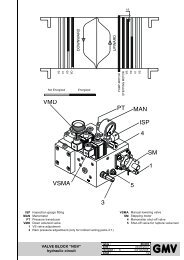
1.3 HOW THE <strong>NGV</strong> <strong>A3</strong> WORKS<br />
The valve <strong>NGV</strong> is made with a non-return valve VR, a control spool VB controlled by a stepping motor and by<br />
a system with pilot operated non-return valve VRP - P<br />
(moved in opening by the electro-valve VMD)<br />
Valve VR It is a valve that prevent , during the downward, the oil inlet to the pump.<br />
It forces the oil that comes from the VRP C2 to pass through the spool VB and then in the<br />
C3 and in the tank T1.<br />
Valve VRP-P It is the pilot operated non-return valve, requested by rules.<br />
During upward the valve works only as ON/OFF, the spool VRP opens or closes<br />
depending on the oil that comes. Its position is determined by the ratio between the<br />
pressure that develops in the chamber C2 and the one that occurs in chamber C1<br />
During downward, instead, it opens the oil way to the valve block (chamber C2).<br />
Its opening is made by the pushing of the piston P that is opened by the pilot operated<br />
valve VMD<br />
Spool VB It’s the main part of the control block.<br />
It adjusts the oil quantity that should be discharged and determines all the movements of<br />
the car<br />
Its movement is controlled by a stepping motor coupled to the spool VB, through a screwnut<br />
coupling (necessary to transform the rotatory motion into translatory).<br />
The spool adjusts both the upward phase (with a direct control of the oil that should be<br />
discharged and, indirectly the oil for the cylinder) than that of downward (directly)<br />
All the other valves have features of safety, pilotage, etc. For example :<br />
MPS+OPP Maximum pressure valve with pilot<br />
5 Overspeed screw<br />
VSMA<br />
Emergency lovering valve<br />
EXP VMD D- E+ E-<br />
<strong>NGV</strong>-<strong>A3</strong>-01<br />
VSMA<br />
PT<br />
7<br />
VMD<br />
BHBL S 11 12 21 22 31 32 41 42 50 5152 V- VSV0V1 V2V3V+ A+PEA-A-<br />
D+ D- E+ E-<br />
FLT<br />
SM<br />
J<br />
C4<br />
P<br />
S2<br />
S3<br />
C2<br />
VB<br />
OPP<br />
C1<br />
M1<br />
VRP C3<br />
5<br />
MPS<br />
S1<br />
VR<br />
VRa<br />
T1
1 0991 483 EN - 06.09.2012<br />
ENG<br />
1.06<br />
10 / 50<br />
<strong>NGV</strong> <strong>A3</strong> <strong>VALVE</strong> <strong>MANUAL</strong><br />
INSTALLATION, USE AND MAINTENANCE<br />
1.4 THE DOUBLE SAFETY<br />
For the double safety the system has two spools in series, the VRP and the VB.<br />
Both work together to stop the car in different ways between upvward and downward<br />
UPWARD<br />
The spool VB controls acceleration and deceleration.<br />
During the approach to the landing, the spool VB, will be almost fully open to discharge a quantity of oil<br />
equal to:<br />
Qt = Qp - Qc<br />
where<br />
Qt = Oil sent to the drain through the VB, Qp= Pump flow<br />
Qc= Flow to the cylinder, corresponding to the car speed<br />
The car stop at the landing is made by opening completely the VB and bringing the value of Qt = Qp. As a<br />
result Qc becomes zero.<br />
The car stops when the pressure of the chamber C2 become equal to the pressure of the chamber C1<br />
(Static pressure of the system). In this case, the VRP spool closes, because is pushed by the pressure and<br />
by the spring, and the car stops at the landing.<br />
DOWNWARD<br />
The downward phase is simpler and, after the opening of the VRP spool, the car speed is controlled by the<br />
VB spool. To a more opening of the spool corresponds an higher speed of the car<br />
The phase of arrival at the landing is determined by the following events:<br />
The VRP spool is opened by the push of the spools P, controlled by the VMD pilot valve<br />
The VB spool closes to stop the car<br />
The VMD valve, raised the landing, is de-energized and consequently the VRP spool closes.<br />
During standard operation of the system, both upward and downward, the proper working of the two<br />
spools (VRP and VB) acting in series, is controlled by three switches :<br />
One, (S1) installed on the VRP, to control the full close position.<br />
Two (S2, S3) installed on the VB, to control the full close and the full open positions<br />
During all phases the system control that the spools reach the correct open and close position.<br />
If this do not happen, the system send an alarm to the control panel, which must turn the system into the<br />
out of service status<br />
WARNING<br />
Needful prerequisite of the control panel, when the system is outside of the doors unlocking zone, is<br />
that it does not send commands to the card and/or the motor / pump.<br />
1.5 MAIN FEATURES<br />
¥"<br />
Valve Type <strong>NGV</strong> <strong>A3</strong><br />
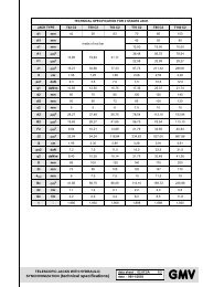
Minimum operating pressure 12 bar<br />
Maximum operating pressure 45 bar<br />
Test speed 1 m/s<br />
Temperature operating range 5°C - 70°C<br />
Rated pump flow range 55 - 600 l/min
<strong>NGV</strong> <strong>A3</strong> <strong>VALVE</strong> <strong>MANUAL</strong><br />
INSTALLATION, USE AND MAINTENANCE<br />
1 0991 483 EN - 06.09.2012<br />
11 / 50<br />
1.06<br />
ENG<br />
2 INSTALLATION OPERATIONS<br />
ATTENTION<br />
During the installation never exclude the safety devices and never connect the motor/pump directly to<br />
the power supply<br />
2.1 HYDRAULIC CONNECTIONS<br />
2.1.1 MINIMUM DIMENSIONS AND HOLES FOR POWER UNIT<br />
2.1.1.1 <strong>VALVE</strong> 1”¼<br />
77.5<br />
137<br />
43.5<br />
14<br />
113<br />
10<br />
11.5<br />
15<br />
1"1/4 G IN<br />
15<br />
135<br />
57<br />
83<br />
35<br />
105<br />
1"1/4 G OUT<br />
61.5<br />
Ø9 x 4 fori<br />
48<br />
52<br />
19 24<br />
6<br />
54.5<br />
M6<br />
Ø28<br />
18<br />
M6<br />
6 16.5 41.5<br />
74<br />
131<br />
310<br />
1" 1 4<br />
OUT<br />
340<br />
393<br />
400<br />
310<br />
1" 1 4<br />
IN
ENG<br />
1.06<br />
1 0991 483 EN - 06.09.2012<br />
12 / 50<br />
<strong>NGV</strong> <strong>A3</strong> <strong>VALVE</strong> <strong>MANUAL</strong><br />
INSTALLATION, USE AND MAINTENANCE<br />
2.1.1.2 <strong>VALVE</strong> 1”½<br />
279.5<br />
77.5 160<br />
42<br />
10<br />
140<br />
10<br />
37<br />
14<br />
6<br />
19<br />
24<br />
M6<br />
6<br />
58<br />
102<br />
Ø28<br />
M6<br />
Ø9 x 4 fori<br />
5x45°<br />
59<br />
15<br />
69<br />
6<br />
16.5<br />
130<br />
1" 1 2 G OUT<br />
1" 1 2 G IN<br />
157<br />
41.5<br />
55<br />
44<br />
230<br />
12<br />
6<br />
310<br />
5<br />
21<br />
161<br />
31<br />
~ 250<br />
~ 432.5<br />
~ 400<br />
~ 310
<strong>NGV</strong> <strong>A3</strong> <strong>VALVE</strong> <strong>MANUAL</strong><br />
INSTALLATION, USE AND MAINTENANCE<br />
1 0991 483 EN - 06.09.2012<br />
13 / 50<br />
1.06<br />
ENG<br />
2.1.2 INPUT AND OUTPUT -POWER UNIT SIDE<br />
2.1.2.1 <strong>VALVE</strong> 1”¼<br />
M8<br />
M8<br />
12x8<br />
PAM<br />
OUT<br />
M8<br />
OUT<br />
1" 1 4<br />
OUT<br />
OUT<br />
M8<br />
OUT<br />
3 4 "<br />
OUT<br />
1" 1 4<br />
IN<br />
M8<br />
OUT<br />
PAM 12x8 IN 1” ¼ OUT 1” ¼ OUT ¾” OUT M8<br />
2.1.2.2 <strong>VALVE</strong> 1”½<br />
M8<br />
OUT<br />
M8<br />
OUT<br />
2"<br />
OUT<br />
M8<br />
OUT<br />
M8<br />
OUT<br />
1"<br />
1 4<br />
OUT<br />
1" 1 2 - 2"<br />
IN<br />
PAM 12x8 IN 1” ½ - 2” OUT 2” OUT 1” ¼ OUT M8
1 0991 483 EN - 06.09.2012<br />
ENG<br />
1.06<br />
14 / 50<br />
<strong>NGV</strong> <strong>A3</strong> <strong>VALVE</strong> <strong>MANUAL</strong><br />
INSTALLATION, USE AND MAINTENANCE<br />
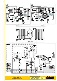
2.2 HYDRAULIC CIRCUIT<br />
<strong>NGV</strong> <strong>A3</strong><br />
VMD<br />
VSMA<br />
7<br />
ML<br />
5<br />
K<br />
J<br />
VB<br />
SM<br />
[E]<br />
VRP<br />
[H]<br />
R/S2<br />
[L]<br />
VC 3006/B<br />
VS1<br />
VR<br />
[H]<br />
R/S1<br />
[L]<br />
[E]<br />
DAL<br />
VRa<br />
1<br />
VS10<br />
10<br />
VR2<br />
VR1<br />
PAM<br />
ISP<br />
6<br />
PT<br />
P<br />
CARD<br />
Ma<br />
M<br />
T<br />
TT<br />
MAN<br />
¥"
<strong>NGV</strong> <strong>A3</strong> <strong>VALVE</strong> <strong>MANUAL</strong><br />
INSTALLATION, USE AND MAINTENANCE<br />
1 0991 483 EN - 06.09.2012<br />
15 / 50<br />
1.06<br />
ENG<br />
2.3 ELECTRICAL CONNECTIONS<br />
2.3.1 CONTROL PANEL REQUIREMENTS<br />
The control panel must send to the power unit at least the following signals:<br />
Mark Signal/comand Features<br />
VS Upward signal 10…40mA 12…48Vdc<br />
V0 Speed : High 10…40mA 12…48Vdc<br />
V1 Speed : Medium 10…40mA 12…48Vdc<br />
V2 Speed : Inspection 10…40mA 12…48Vdc<br />
V3 Speed : Micro-levelling 10…40mA 12…48Vdc<br />
D+ Downward signal 12…48Vdc, 60…180Vdc<br />
D- Downward negative pole 12…48Vdc, 60…180Vdc<br />
The control panel must to receive and to understand correctly at least the following signals:<br />
Mark Signal/comand Features<br />
RDY Ready 10mA…2A<br />
RUN Run 10mA…2A<br />
UP* Up 10mA…2A<br />
OVL Overload 10mA…2A<br />
*Command used only to interface control panels that need different signals to start upward or doward travels<br />
Outputs RDY, RUN and UP<br />
- report to control panel about the system state,<br />
- determine when the control panel must start or stop the motor /pump<br />
WARNING<br />
The control panel, when receive a FAULT signal from the <strong>NGV</strong>-<strong>A3</strong> card (RUN and RDY output),<br />
should not send commando to the valve and/or the motor/pump<br />
In FAULT condition the motor/pump group should NOT be active<br />
WARNING<br />
To detect the unintended movement of the car the system use the circuit required by paragraph 7.7.1<br />
and 14.2.1.2 of the rule EN 81-2:2010. This circuit, if it detects a movement of the car, with doors not<br />
closed, outside the unlocking zone, prevents the control panel to send any command to the valve.<br />
The system restore should be performed only by an authorized and properly trained person.<br />
• Distance of setting: ± 200 mm<br />
• Maximum time for the intervention of the circuit 270 ms<br />
For other data or signals sequence see next paragraphs of this manual<br />
2.3.2 INTERVENTION TIME<br />
0 Origin<br />
1 Car speed in the instant of<br />
intervention of the bracking<br />
device ≤ 1,3 m/s<br />
2 Speed<br />
3 Response time of the device that<br />
detects the unintended movement<br />
of the car ≤ 270 ms<br />
4 Response time of the braking<br />
devices ≤ 200 ms<br />
5 Time<br />
6 Time from start of the unintended<br />
movement to the instant in which<br />
the car sensor leaves the doors<br />
area (dimension = ± 200 mm)<br />
7 Stoping time of the car ≤ 500 ms<br />
8 Point in which the car stops<br />
0-8 between 0 and 8 the maximum<br />
distance travelled is ≤ 100 cm<br />
2<br />
1<br />
0 6 3 4 7 8<br />
5
ENG<br />
1.06<br />
1 0991 483 EN - 06.09.2012<br />
16 / 50<br />
<strong>NGV</strong> <strong>A3</strong> <strong>VALVE</strong> <strong>MANUAL</strong><br />
INSTALLATION, USE AND MAINTENANCE<br />
2.3.3 FAULT SCHEMAS<br />
A control panel installed with the valve <strong>NGV</strong> <strong>A3</strong> must continuously monitor the signals RDY and RUN (UP)<br />
that it receives from the card <strong>NGV</strong><strong>A3</strong>-xx.<br />
The control panel should go in error status, stop the system and do not send commands to the valve and / or<br />
the motor / pump when, for more than 2s, signals RDY and RUN are simultaneously in the same condition.<br />
The contemporary of the ON or OFF status require different behaviours, in particular:<br />
If RDY and RUN are both in ON status, the control panel must detect the error, move the car to the nearest<br />
landing and stop the system without allowing more travels;<br />
If RDY and RUN are both in OFF status, the control panel must stop immediately the system and prevent any<br />
further movement with the exception of the manual emergency operation.<br />
IN : VS / D<br />
ON<br />
OFF<br />
OK<br />
OUT : RDY<br />
ON<br />
OFF<br />
OUT : RUN<br />
ON<br />
OFF<br />
2s<br />
OK<br />
ALLOWED<br />
2s<br />
OUT : RDY<br />
ON<br />
OFF<br />
OUT : RUN<br />
ON<br />
OFF<br />
RDY FAULT<br />
OUT : RDY<br />
ON<br />
OFF<br />
OUT : RUN<br />
ON<br />
OFF<br />
RUN FAULT<br />
2s<br />
2s<br />
OK<br />
ALLOWED FAULT<br />
2.4 OPERATIONS PRELIMINARY TO CONNECTION<br />
0 - OFF 0 - OFF +
<strong>NGV</strong> <strong>A3</strong> <strong>VALVE</strong> <strong>MANUAL</strong><br />
INSTALLATION, USE AND MAINTENANCE<br />
1 0991 483 EN - 06.09.2012<br />
17 / 50<br />
1.06<br />
ENG<br />
2.5 SCHEMAS OF THE CONNECTIONS TO CONTROL PANELS<br />
In the following pages the schemas of the connections between valve / <strong>NGV</strong><strong>A3</strong> card and control panels<br />
2.5.1 MAIN SCHEMA<br />
<strong>NGV</strong>-<strong>A3</strong><br />
VAL<br />
VMD D-E+E-<br />
X7<br />
<strong>A3</strong>-Sxx-Wxx<br />
S1<br />
B<br />
S3ò<br />
PT<br />
MAN<br />
4<br />
ISP<br />
VMD<br />
(1)<br />
PAMï<br />
VSMA<br />
ML<br />
3 5<br />
S2ñ<br />
SM<br />
1<br />
D+ D-E+E-<br />
X6<br />
TT<br />
C°<br />
BOX<br />
EXP<br />
X12 X11 X10 X9 X8<br />
T<br />
µSD<br />
X13<br />
+ -<br />
+ -<br />
+ - T+ T- P+ P-<br />
X7<br />
<strong>NGV</strong>-<strong>A3</strong>-01<br />
X14<br />
PT01<br />
X15<br />
COMM<br />
BHBL S 11 12 21 22 31 32 41 42 50 5152 A+PEA-A-<br />
X2<br />
X4<br />
X5<br />
X3<br />
X1<br />
CAN BUS<br />
PMIN<br />
PMAX<br />
OVL<br />
UP<br />
RUN<br />
RDY<br />
COM<br />
CARD<br />
D+ D- E+ E-<br />
X6<br />
QM<br />
2A max<br />
S00 / S48<br />
W25 / W50<br />
¥"
ENG<br />
1.06<br />
1 0991 483 EN - 06.09.2012<br />
18 / 50<br />
<strong>NGV</strong> <strong>A3</strong> <strong>VALVE</strong> <strong>MANUAL</strong><br />
INSTALLATION, USE AND MAINTENANCE<br />
CARD<br />
2.5.2 CONNECTION SCHEMAS FOR SIGNALS<br />
Schema S00<br />
S00<br />
CARD<br />
Schema S48<br />
S48<br />
J6<br />
J6<br />
X4<br />
D+ D- E+ E-<br />
X6<br />
X4<br />
A+PEA-A-<br />
X5<br />
A+PEA-A-<br />
X5<br />
D+ D- E+ E-<br />
X6<br />
QM<br />
V+<br />
V3<br />
V2<br />
V1<br />
V0<br />
VS<br />
QM<br />
10...48 VDC<br />
V3<br />
V2<br />
V1<br />
V0<br />
VS<br />
- +<br />
CARD<br />
2.5.3 CONNECTION SCHEMAS FOR POWER<br />
Schema W50<br />
W50<br />
CARD<br />
Schema W25<br />
W25<br />
J6<br />
J6<br />
X4<br />
D+ D- E+ E-<br />
X6<br />
X4<br />
A+PEA-A-<br />
X5<br />
A+PEA-A-<br />
X5<br />
D+ D- E+ E-<br />
X6<br />
QM<br />
QM<br />
24 VDC = +/- 10%<br />
50W<br />
- +<br />
J6=1-2<br />
12- 48 VDC<br />
24 VDC = +/- 10%<br />
25W<br />
- +<br />
12- 48 VDC J6=1-2<br />
60-180 VDC J6=2-3<br />
PE<br />
EN81-2<br />
PE<br />
EN81-2<br />
VAL <strong>NGV</strong> valve QM Control panel BOX <strong>NGV</strong> interface box<br />
VSMA Emergency downward valve V0 High speed VS Upward signal<br />
VMD Downward solenoid valve V1 Medium speed CARD <strong>NGV</strong> control card<br />
SM Stepping motor V2 Inspection speed S1,S2,S3 Sensors (VRP,VBO, VBC)<br />
D Downward signal V3 Micro-levelling speed PT Pressure transducer<br />
(1) Schema of the connections between D+D-E+E-VMD TT Temperature transducer<br />
~<br />
~<br />
V 18÷30V~<br />
18÷30V~<br />
- + -<br />
L ~ A+<br />
A+<br />
+<br />
A+<br />
N<br />
+<br />
24÷40 V<br />
2200÷4700 µ F<br />
A-<br />
=<br />
~<br />
~<br />
50V<br />
A-<br />
A-
J1<br />
X14<br />
X15<br />
EXP X12 X11 X10 X9 X8 VMD D- E+E-<br />
X7<br />
+ - J2 + -J3<br />
+ - T+ T- P+ P-<br />
X13<br />
3 3<br />
<strong>NGV</strong>-<strong>A3</strong>-01<br />
1 1<br />
BH BLS 11122122 31324142 505152 A- V- VSV0V1V2V3V+ A+PEA-A-<br />
X2<br />
X4<br />
X5<br />
X3<br />
X1<br />
J6<br />
3<br />
1<br />
D+ D- E+ E-<br />
X6<br />
J1<br />
J1<br />
X14<br />
X15<br />
EXP X12 X11 X10 X9 X8 VMD D- E+E-<br />
X7<br />
+ - J2 + -J3<br />
+ - T+ T- P+ P-<br />
X13<br />
3 3<br />
<strong>NGV</strong>-<strong>A3</strong>-01<br />
1 1<br />
BH BLS 11122122 31324142 505152 A- V- VSV0V1V2V3V+ A+PEA-A-<br />
X2<br />
X4<br />
X5<br />
X3<br />
X1<br />
X14<br />
X15<br />
J6<br />
3<br />
1<br />
D+ D- E+ E-<br />
X6<br />
EXP X12 X11 X10 X9 X8 VMD D- E+E-<br />
X7<br />
+ - J2 + -J3<br />
+ - T+ T- P+ P-<br />
X13<br />
3 3<br />
<strong>NGV</strong>-<strong>A3</strong>-01<br />
1 1<br />
BH BLS 11122122 31324142 505152 A- V- VSV0V1V2V3V+ A+PEA-A-<br />
X2<br />
X4<br />
X5<br />
X3<br />
X1<br />
J6<br />
3<br />
1<br />
D+ D- E+ E-<br />
X6<br />
<strong>NGV</strong> <strong>A3</strong> <strong>VALVE</strong> <strong>MANUAL</strong><br />
INSTALLATION, USE AND MAINTENANCE<br />
1 0991 483 EN - 06.09.2012<br />
19 / 50<br />
1.06<br />
ENG<br />
2.6 CONNECTIONS TO THE TERMINAL<br />
230-400V 400-690V<br />
RO<br />
RO1<br />
RO2<br />
TO<br />
TO2<br />
TO1<br />
RT<br />
RT2<br />
RT1<br />
V2<br />
W1<br />
M<br />
3~<br />
U2<br />
V1<br />
W2<br />
U1<br />
230V Δ Y-Δ -<br />
400V Y Δ Y-Δ<br />
Δ<br />
RO - Oil heating resistance<br />
RO1<br />
RO2<br />
TO2<br />
TO1<br />
RT2<br />
RT1<br />
V2<br />
W1<br />
U2<br />
V1<br />
W2<br />
U1<br />
TO - Oil thermostat<br />
RT - Motor thermistors<br />
150 mm<br />
RO<br />
TO<br />
RT<br />
M<br />
3~<br />
RO<br />
TO<br />
RT<br />
M<br />
3~<br />
U1<br />
W2<br />
V1<br />
U2<br />
W1<br />
V2<br />
RT1<br />
RT2<br />
TO1<br />
TO2<br />
RO1<br />
RO2<br />
U1<br />
W2<br />
V1<br />
U2<br />
W1<br />
V2<br />
RT1<br />
RT2<br />
TO1<br />
TO2<br />
RO1<br />
RO2<br />
Y-Δ<br />
Y<br />
U1<br />
W2<br />
V1<br />
U2<br />
W1<br />
V2<br />
RT1<br />
RT2<br />
TO1<br />
TO2<br />
RO1<br />
RO2<br />
U1<br />
W2<br />
V1<br />
U2<br />
W1<br />
V2<br />
RT1<br />
RT2<br />
TO1<br />
TO2<br />
RO1<br />
RO2<br />
150 mm<br />
150 mm<br />
2.7 CONNECTIONS TO THE CARD<br />
X12 X11 X10 X9 X8<br />
EXP VMD D- E+ E-<br />
J1<br />
X13<br />
+ - + - + - T+ T- P+ P-<br />
J2<br />
J3<br />
3 3<br />
X7<br />
<strong>NGV</strong>-<strong>A3</strong>-01<br />
1<br />
1<br />
ò<br />
X1-X2-X3<br />
X14<br />
÷÷÷<br />
X15<br />
BHBL S 11 12 21 22 31 32 41 42 50 5152 A- V- VSV0 V1 V2V3V+ A+PEA-A-<br />
X2<br />
X4<br />
X5<br />
3<br />
J6<br />
1<br />
D+ D- E+ E-<br />
X6<br />
§ 2.7<br />
X1<br />
X3<br />
X12 X11 X10 X9 X8<br />
EXP VMD D- E+ E-<br />
J1<br />
X13<br />
+ - + - + - T+ T- P+ P-<br />
J2<br />
J3<br />
3 3<br />
X7<br />
<strong>NGV</strong>-<strong>A3</strong>-01<br />
1<br />
1<br />
ô<br />
X4-X5-X6<br />
X14<br />
X15<br />
X1<br />
ø øø<br />
BHBL S 11 12 21 22 31 32 41 42 50 5152 A- V- VSV0 V1 V2V3V+ A+PEA-A-<br />
X2<br />
X4<br />
X5<br />
X3<br />
J6<br />
3<br />
1<br />
D+ D- E+ E-<br />
X6<br />
§ 2.7<br />
J6<br />
3<br />
2<br />
1<br />
VMD<br />
= 12-48 Vdc<br />
J1<br />
X14<br />
X12 X11 X10 X9 X8<br />
EXP VMD D- E+ E-<br />
X7<br />
+ - + - + - T+ T- P+ P-<br />
J2<br />
J3<br />
<strong>NGV</strong>-<strong>A3</strong>-01<br />
X13<br />
3 3<br />
1 1<br />
3<br />
2<br />
1<br />
=<br />
60-180<br />
Vdc<br />
X15<br />
BHBL S 11 12 21 22 31 32 41 42 50 5152 A- V- VSV0 V1 V2V3V+ A+PEA-A-<br />
X2<br />
X4<br />
X5<br />
X3<br />
X1<br />
ø<br />
3<br />
J6<br />
1<br />
D+ D- E+ E-<br />
X6
ENG<br />
1.06<br />
1 0991 483 EN - 06.09.2012<br />
20 / 50<br />
<strong>NGV</strong> <strong>A3</strong> <strong>VALVE</strong> <strong>MANUAL</strong><br />
INSTALLATION, USE AND MAINTENANCE<br />
ñ<br />
2.8 CONNECTION OF HYDRAULIC PIPES<br />
8 ÷ 36 3/4" x 3/4" 3/4" - 3/4" x 3/4" 3/4"<br />
3/4" 3/4"<br />
42 ÷ 52<br />
3/4" x M36" - 3/4" x M36<br />
1”<br />
1”<br />
55 ÷ 100 - 1” x M36<br />
- 1” x M36<br />
1”<br />
100 ÷ 150<br />
1” x M45 1” x M45<br />
1”1/4 35<br />
1”1/4<br />
180 ÷ 216 1”1/4 1”1/4<br />
1”1/4 x M45<br />
1”1/4 x M45<br />
1”1/4GM x 1”1/2GF<br />
250 ÷ 300<br />
1”1/4<br />
+ 1”1/2 x M52 1”1/2 42 1”1/2 x M52 1”1/2<br />
-<br />
360 ÷ 432 1”1/2 1”1/2 x M52<br />
1”1/2<br />
500 ÷ 600<br />
2” 2” x 2” 2” - 2” x 2” 2”<br />
2.8.1 CONNECTION WITH FLEXIBLE HOSE<br />
• Remove the gear and the cutting ring from the terminal<br />
connection of the silencer.<br />
• Ensure that the terminal connection is well fixed on the<br />
silencer.<br />
• Clean and oil the threading and their seats.<br />
• Fix the flexible hose verifying it is thoroughly tightened.<br />
WARNING<br />
Ensure that there is no dirty inside the tube. These<br />
impurities could damage the sealing of the piston and of<br />
the valve block and inhibit the correct operation of the<br />
system.<br />
2.8.2 CONNECTION WITH A RIGID PIPE<br />
• Cut at 90° the head of the tube with a saw (do not use a tube-cutter)<br />
• Do not let metal residuals fall into the tube and eliminate the burrs internally and externally.<br />
• Remove the gear and the cutting ring of the terminal connection and insert it on the pipe.<br />
• Ensure that the cutting ring is inserted as indicated in image<br />
• Ensure that the terminal connection is well fixed on the silencer.<br />
• Clean and lubricate the threading and the connection seat with<br />
a slight oil veil.<br />
• Insert the pipe into the cone at 24° up to lay it on the stop limit<br />
of the cone itself.<br />
• Screw thoroughly the gear by hand until it is felt that the cutting<br />
gear lays perfectly to the nut.<br />
• Then screw the nut using a wrench until the cutting edge of the<br />
ring is in contact with the tube and prevents it from rotating.<br />
• Keep the tube against its stop to avoid it rotates, screw the<br />
fixing nut by 3/4 rev. In doing so the ring engraves with the<br />
necessary depth the external part of the tube and rises a<br />
border in front of its cutting edge.<br />
• Loose the nut and check that the tube has all around a well<br />
risen border. The border must cover 70% of the front part of<br />
the cutting ring.<br />
• Fix the tube, close the nut with a wrench until a certain<br />
resistance is felt; from this moment on screw for a further 1/4<br />
turn, contrasting wrench against wrench.<br />
WARNING<br />
Ensure that there is no dirty inside the tube. These impurities could damage the sealing of the piston<br />
and of the valve block and inhibit the correct operation of the plant.
X14<br />
X15<br />
X1<br />
BHBL S 50 5152<br />
X2<br />
X14<br />
X15<br />
X1<br />
BHBL S 50 5152<br />
X2<br />
X3<br />
X3<br />
A-<br />
A-<br />
<strong>NGV</strong> <strong>A3</strong> <strong>VALVE</strong> <strong>MANUAL</strong><br />
INSTALLATION, USE AND MAINTENANCE<br />
1 0991 483 EN - 06.09.2012<br />
21 / 50<br />
1.06<br />
ENG<br />
3 <strong>NGV</strong> <strong>A3</strong> CONTROL BOARD<br />
3.1 ELECTRICAL FEATURES<br />
The hardware features of the card <strong>NGV</strong>-<strong>A3</strong> are:<br />
# DESCRIPTION VALUE<br />
01 Standard supply voltage 24V=, ±10%<br />
02 Extended supply voltage 12...42Vdc<br />
03 Maximum consumption 25W<br />
04 Voltage input VS-V0-V1-V2-V3 10...48Vdc (70Vp)<br />
05 Voltage input D+ (VMD), two range selectable by jumper 12...48Vdc / 60...180Vdc<br />
06 Power voltage sensors VRP and VB 12Vdc<br />
07 Power voltage pressure transducer 12Vdc<br />
08<br />
Relays output, Volt free contact<br />
according with EN81-2 for distances and insulation up to 250V<br />
10mA@20Vdc / 2A@250Vac<br />
3.2 PERFORMANCES<br />
The card <strong>NGV</strong>-<strong>A3</strong>-01 has 3 different versions:<br />
-01 Standard version : with power supply 24VDC<br />
-02 Extended version : with all the available functions<br />
-03 Reduced version : with power supply 24VDC and only serial connection on can bus<br />
# FUNCTION DESCRIPTION<br />
VERSION<br />
01 02 03<br />
01 Power supply Standard, 24V=, ±10% / Extended, 12...42Vdc S E S<br />
02 Opto-isolated inputs to command upward and speed level 5 5 -<br />
03 Opto-isolated input to command downward (separate) 1 1 1<br />
04<br />
Relay output with voltage free contact<br />
according to EN81-2 for distances and isolation up to 250V<br />
7 7 -<br />
05<br />
Step Motor Command 12...52Vdc, 1,5Arms<br />
with the possibility of monitoring the rated current and the connection breaking.<br />
1 1 1<br />
06 Input for pressure transducer interface, range 0...100 bar 1 1 1<br />
07 Input for oil temperature transducer interface, range 0...100°C 1 1 1<br />
08 Input for sensor ON/OFF 12V or linear sensor 0...5V (power supply 12V) 2 2 2<br />
09 Input for sensor ON/OFF 12V 1 1 1<br />
10 Rj45 port for PT01 / Pc / remote 2 2 1<br />
11 Slot for µSD card - 1 -<br />
12 Calendar watch with CR2030 battery 1 1 -<br />
13 Can bus serial socket - 1 1<br />
14 I/O extender connector 1 1 1<br />
3.2.1 SIGNALLERS<br />
GREEN LED OFF Not powered<br />
Power supply<br />
FLASHING Power out of range<br />
status<br />
11 12 21 22 31 32 41 42<br />
ON<br />
Correctly powered<br />
11 12 21 22 31 32 41 42<br />
RED LED OFF No alarm<br />
Alarm status FLASHING Alarm that stops the system work<br />
ON<br />
Alarm that do not stops the system work<br />
PT01<br />
Card status DISPLAY Show errors and settings
X3<br />
X3<br />
X3<br />
X14<br />
X15<br />
X1<br />
X14<br />
X15<br />
X1<br />
X14<br />
X15<br />
X1<br />
X2<br />
X2<br />
÷<br />
X4<br />
X4<br />
X4<br />
X5<br />
X5<br />
X5<br />
J6<br />
J6<br />
X3<br />
X3<br />
X3<br />
X6<br />
X6<br />
X6<br />
ENG<br />
1.06<br />
1 0991 483 EN - 06.09.2012<br />
22 / 50<br />
<strong>NGV</strong> <strong>A3</strong> <strong>VALVE</strong> <strong>MANUAL</strong><br />
INSTALLATION, USE AND MAINTENANCE<br />
3.3 CONNECTIONS<br />
3.3.1 CONTROL PANEL INTERFACE<br />
The input circuits are divided in two groups, both isolated from the card power supply:<br />
• V0,V1,V2,VS with common V- • D+ with common D-<br />
Each group can be powered or by an external source within established limits, or directly by the card power,<br />
connecting the commons (V- and/or D-) to the A-.<br />
The interfacing with the control panel is made via removable terminal connectors defined as follows:<br />
Connector X1, step 3,5 mm<br />
Pos. Mark Features Description<br />
1 BH Bus Can bus H<br />
2 BL Bus Can bus L<br />
3 SH Shield Shield<br />
Connector X2, step 5,0 mm<br />
Pos. Mark Features Description<br />
1 11 10mA...2A Programmable output relay (refer to programming<br />
2 12 20...250V menu and programmable functions chart)<br />
3 21 10mA...2A Programmable output relay (refer to programming<br />
4 22 20...250V menu and programmable functions chart)<br />
5 31 10mA...2A Programmable output relay (refer to programming<br />
6 32 20...250V menu and programmable functions chart)<br />
7 41 10mA...2A Programmable output relay (refer to programming<br />
8 42 20...250V menu and programmable functions chart)<br />
Connector X3 step 3,5 mm<br />
Pos. Mark Features Description<br />
1 50<br />
10mA...2A<br />
20...250V<br />
Output: RUN (NO)<br />
2 51<br />
10mA...2A<br />
20...250V<br />
Output: RDY (NO)<br />
3 52<br />
10mA...2A<br />
20...250V<br />
Common<br />
Connector X4, step 3,5 mm<br />
Pos. Mark Features Description<br />
1 A- Power : negative (-)<br />
2 V-<br />
Inputs : negative<br />
Make a short circuit with A- if you use V+ as power<br />
or connect to input negative pole.<br />
3 VS Input command : upward<br />
4 V0 Input command : speed : high (nominal speed)<br />
12...48Vdc,<br />
5 V1 Input command : speed : medium<br />
10...40mA<br />
6 V2 Input command : speed : inspection<br />
7 V3<br />
Input command : speed : micro-levelling<br />
8 V+<br />
Power : positive common.<br />
For input command circuits without voltage.<br />
Do NOT use if input commands are under voltage<br />
Connector X5, step 3,5 mm<br />
Pos. Mark Features Description<br />
1 A+ Power : positive<br />
2 PE PE, ground<br />
3 A- Power : negative<br />
4 A- Power : negative<br />
Connector X6, step 5,0 mm<br />
Pos. Mark Features Description<br />
1 D+ 12...48Vdc, Input command : downward<br />
2 D- 60...180Vdc Input downward : negative<br />
3 E+ Input command : emergency solenoid valve<br />
4 E- Input emergency solenoid valve : negative<br />
BHBL S 11 12 21 22 31 32 41 42 50 5152<br />
X2÷<br />
BHBL S 11 12 21 22 31 32 41 42 50 5152<br />
BHBL S 11 12 21 22 31 32 41 42 50 5152<br />
ø<br />
52 A- V- VSV0V1 V2V3V+ A+PEA-A-<br />
ø<br />
52 A- V- VSV0V1V2V3V+ A+PEA-A-<br />
3<br />
1<br />
D+ D- E+ E-<br />
3<br />
1<br />
D+ D- E+ E-<br />
3<br />
øJ6<br />
1<br />
52 A- V- VSV0V1V2V3V+ A+PEA-A-<br />
D+ D- E+ E-<br />
A-
X3<br />
X12 X11 X10 X9 X8<br />
X12 X11 X10 X9 X8<br />
X12 X11 X10 X9 X8<br />
X12 X11 X10 X9 X8<br />
X12 X11 X10 X9 X8<br />
X12 X11 X10 X9 X8<br />
X12 X11 X10 X9 X8<br />
X12 X11 X10 X9 X8<br />
X4<br />
X5<br />
J6<br />
X6<br />
X7<br />
X7<br />
X7<br />
X7<br />
X7<br />
X7<br />
X7<br />
X7<br />
<strong>NGV</strong> <strong>A3</strong> <strong>VALVE</strong> <strong>MANUAL</strong><br />
INSTALLATION, USE AND MAINTENANCE<br />
1 0991 483 EN - 06.09.2012<br />
23 / 50<br />
1.06<br />
ENG<br />
Jumper J6 (to set connector X6 D+ D-)<br />
Pos.<br />
Description<br />
1-2<br />
2-3<br />
3<br />
2<br />
1<br />
3<br />
2<br />
1<br />
Input and downward command VMD 12…48Vdc<br />
Input and downward command VMD 60…180Vdc 52<br />
3.3.2 <strong>VALVE</strong> INTERFACE<br />
The valve interfacing is made by these connections:<br />
Connector X7, step 5,0 mm<br />
Pos. Mark Features Description<br />
1 VMD<br />
Downward command VMD<br />
2 D-<br />
3 E+<br />
Emergency solenoid valve<br />
4 E-<br />
Connector X8, step 2,0 mm<br />
Pos. Mark Features Description<br />
1 PHA1<br />
Winding of motor phase 1<br />
2 PHA2<br />
3 PHB1<br />
Winding of motor phase 2<br />
4 PHB2<br />
Connector X9, step 3,5 mm<br />
Pos. Mark Features Description<br />
1 T+ +Ref<br />
2 T- 2KΩ max.<br />
Temperature transducer PTC, 1KΩ a 25°C<br />
3 P+ +12Vdc<br />
4 P- 4…20mA return<br />
Pressure transducer<br />
Connector X10, step 3,5 mm - (SensorS1 VRP - Settable)<br />
Pos. Mark Features Description<br />
1 + +12Vdc<br />
2 0…12Vdc / 0…5V Sensor ON/OFF (12Vdc) / Linear sensor 0…5V<br />
3 - 0V<br />
Jumper J3 (to set connector X10)<br />
Pos.<br />
Description<br />
1-2<br />
2-3<br />
3<br />
2<br />
1<br />
3<br />
2<br />
1<br />
Sensor S1 VRP (ON/OFF)<br />
Linear Sensor 0…5V<br />
Connector X11, step 3,5 mm - (Sensor S2 VB Close - Settable)<br />
Pos. Mark Features Description<br />
1 + +12Vdc<br />
2 0…12Vdc / 0…5V Sensor ON/OFF (12Vdc) / Linear sensor 0…5V<br />
3 - 0V<br />
Jumper J2 (to set connector X11)<br />
Pos.<br />
Description<br />
1-2<br />
2-3<br />
3<br />
2<br />
1<br />
3<br />
2<br />
1<br />
Sensor S2 VB (ON/OFF)<br />
Linear Sensor 0…5V<br />
Connector X12, step 3,5 mm - (SensorS1 VB Open)<br />
Pos. Mark Features Description<br />
1 + +12Vdc<br />
2 0…12Vdc Sensor ON/OFF (12Vdc)<br />
3 - 0V<br />
A- V- VSV0V1V2V3V+ A+PEA-A-<br />
3<br />
1<br />
D+ D- E+ E-<br />
VMD D- E+ E-<br />
ö<br />
+ - J2 + - J3 + - T+ T- P+ P-<br />
3 3<br />
<strong>NGV</strong>-<strong>A3</strong>-01<br />
1 1<br />
VMD D- E+ E-<br />
ö<br />
+ - J2 + - J3 + - T+ T- P+ P-<br />
3 3<br />
<strong>NGV</strong>-<strong>A3</strong>-01<br />
1 1<br />
VMD D- E+ E-<br />
õ<br />
+ - J2 + - J3 + - T+ T- P+ P-<br />
3 3<br />
<strong>NGV</strong>-<strong>A3</strong>-01<br />
1 1<br />
õ<br />
+ - J2 + - J3 + - T+ T- P+ P-<br />
3 3<br />
1 1<br />
+ - J2 + - J3 + - T+ T- P+ P-<br />
3 3<br />
õ<br />
1 1<br />
õ<br />
+ - J2 + - J3 + - T+ T- P+ P-<br />
3 3<br />
1 1<br />
+ - J2 + - J3 + - T+ T- P+ P-<br />
3<br />
õ<br />
3<br />
1 1<br />
õ<br />
+ - J2 + - J3 + - T+ T- P+ P-<br />
3 3<br />
1 1<br />
VMD D- E+ E-<br />
<strong>NGV</strong>-<strong>A3</strong>-01<br />
VMD D- E+ E-<br />
<strong>NGV</strong>-<strong>A3</strong>-01<br />
VMD D- E+ E-<br />
<strong>NGV</strong>-<strong>A3</strong>-01<br />
VMD D- E+ E-<br />
<strong>NGV</strong>-<strong>A3</strong>-01<br />
VMD D- E+ E-<br />
<strong>NGV</strong>-<strong>A3</strong>-01
J1<br />
J1<br />
J1<br />
X14<br />
X14<br />
X14<br />
X14<br />
X15<br />
X1<br />
X13<br />
X13<br />
X13<br />
X3<br />
X12<br />
X12<br />
X12<br />
ENG<br />
1.06<br />
1 0991 483 EN - 06.09.2012<br />
24 / 50<br />
<strong>NGV</strong> <strong>A3</strong> <strong>VALVE</strong> <strong>MANUAL</strong><br />
INSTALLATION, USE AND MAINTENANCE<br />
3.3.3 USER INTERFACE<br />
Connector X13, step 2,54 mm - (AUX 2 x 13)<br />
Connector for extensions (Encoder, …)<br />
EXP<br />
õ<br />
+ - J2<br />
3<br />
1<br />
Slot J1, µSD (serial SPI)<br />
Slot for µSD memory cards (serial SPI)<br />
Connector X14, RJ45 (PT01)<br />
Socket RS232 for programmer PT01<br />
Pos. Mark Features Description<br />
1 +12 Power : 12Vdc<br />
2 +12 Power : 12Vdc<br />
3 RxD Data output (to PT01)<br />
4 TxD Data input (from PT01)<br />
5 Not in use<br />
6 Not in use<br />
7 0V Power : negative<br />
8 0V Power : negative<br />
Connector X15, RJ45 (COMM)<br />
Socket RS232 for PC, Modem, …<br />
Pos. Mark Features Description<br />
1 +12 Power : 12Vdc<br />
2 +12 Power : 12Vdc<br />
3 RxD Data output (to Pc, Modem,…)<br />
4 TxD Data input (from Pc, modem,..)<br />
5 Not in use<br />
6 Not in use<br />
7 0V Power : negative<br />
8 0V Power : negative<br />
EXP<br />
õ<br />
EXP<br />
÷<br />
BHBL S 11 12 21 22 31 32 41 42 50 5152<br />
X2÷<br />
+ - J2<br />
3<br />
1<br />
+ - J2<br />
3<br />
1<br />
A-<br />
VB OPEN VB CLOSE VRP TT PT<br />
EXP<br />
X12 X11 X10 X9 X8<br />
VMD D- E+ E-<br />
J1<br />
X13<br />
+ - J2 + - J3 + - T+ T- P+ P-<br />
3 3<br />
X7<br />
<strong>NGV</strong>-<strong>A3</strong>-01<br />
µSD<br />
LED GREEN<br />
1<br />
1<br />
LED RED<br />
X14<br />
PT01<br />
COMM<br />
X15<br />
J6<br />
3<br />
1<br />
BHBL S 11 12 21 22 31 32 41 42 50 5152 A- V- VSV0 V1 V2V3V+ A+PEA-A-<br />
X1<br />
CAN BUS<br />
X2<br />
AUX OUT<br />
RUN<br />
RDY<br />
COM<br />
X3<br />
X4<br />
X5<br />
D+ D- E+ E-<br />
X6
C<br />
O<br />
M<br />
R<br />
E<br />
A<br />
D<br />
YR<br />
U<br />
N<br />
µSD<br />
EXP<br />
<strong>NGV</strong> <strong>A3</strong> <strong>VALVE</strong> <strong>MANUAL</strong><br />
INSTALLATION, USE AND MAINTENANCE<br />
1 0991 483 EN - 06.09.2012<br />
25 / 50<br />
1.06<br />
ENG<br />
3.4 SIGNALS AND COMMANDS SEQUENCE<br />
3.4.1 UPWARD DIAGRAM<br />
V<br />
[m/s]<br />
VN<br />
0<br />
C<br />
[mm]<br />
Close<br />
0 1<br />
6<br />
7<br />
8<br />
9 10<br />
11<br />
18<br />
(0)<br />
VB/SM<br />
4<br />
5<br />
12<br />
13<br />
14<br />
15<br />
Open<br />
2<br />
3<br />
16 17<br />
ö<br />
ð<br />
ð<br />
MP<br />
VX<br />
VS<br />
ö<br />
ø<br />
ø<br />
CAN<br />
BUS<br />
AUX OUT<br />
RJ45<br />
PT01<br />
LED GREEN<br />
LED RED<br />
<strong>NGV</strong>-<strong>A3</strong>-01<br />
ï<br />
ï<br />
õ<br />
RDY<br />
RUN<br />
UP<br />
DRAL,S<br />
ï<br />
ï<br />
÷<br />
VB<br />
OPEN<br />
VB<br />
CLOSE<br />
VRP TT PT<br />
3.4.1.1 UPWARD SIGNALS AND COMMANDS SEQUENCE<br />
Start travel sequence : RDY=ON + RUN=OFF ð (Vx=ON ð) VS=ON ð RDY=OFF – VB/SM=OPEN ð<br />
RUN/UP=ON (ð MP=ON)<br />
End travel sequence : (Vx=OFF ð VS=OFF ð) VB/SM=OPEN ð RUN/UP=OFF ð (MP=OFF ð)<br />
VB/SM=CLOSE ð RDY=ON<br />
MP Motor / pump Vx = V0, V1, V2 Speed (High, Intermediate, Inspection)<br />
SM Stepping Motor VS Upward command<br />
V S V 0 V 1 V 2 V 3<br />
Speed : High 1 1 0 0 0 1 Powered<br />
Speed : Medium 1 X 1 0 0 0 Not powered<br />
Speed : Inspection 1 X X 1 0 X Anything<br />
Speed : levelling / re-levelling 1 0 0 0 0
C<br />
O<br />
M<br />
R<br />
E<br />
A<br />
D<br />
U<br />
YR<br />
N<br />
µSD<br />
EXP<br />
ENG<br />
1.06<br />
1 0991 483 EN - 06.09.2012<br />
26 / 50<br />
<strong>NGV</strong> <strong>A3</strong> <strong>VALVE</strong> <strong>MANUAL</strong><br />
INSTALLATION, USE AND MAINTENANCE<br />
3.4.2 DOWNWARD DIAGRAM<br />
V<br />
[m/s]<br />
VN<br />
0<br />
C<br />
[mm]<br />
Close<br />
0 1<br />
2<br />
3<br />
10<br />
9<br />
12<br />
11<br />
(0)<br />
VB/SM<br />
Open<br />
4<br />
5<br />
6<br />
7<br />
8<br />
ö<br />
ð<br />
VX<br />
D<br />
ø<br />
ð<br />
CAN<br />
BUS<br />
AUX OUT<br />
RJ45<br />
PT01<br />
LED GREEN<br />
LED RED<br />
<strong>NGV</strong>-<strong>A3</strong>-01<br />
ï<br />
ï<br />
RDY<br />
RUN<br />
ï<br />
ï<br />
VB<br />
OPEN<br />
VB<br />
CLOSE<br />
VRP TT PT<br />
÷<br />
VMD<br />
DRAL,D<br />
÷<br />
Start travel<br />
sequence :<br />
End travel<br />
sequence :<br />
3.4.2.1 DOWNWARD SIGNALS AND COMMANDS SEQUENCE<br />
RDY=ON+RUN=OFF ð Vx=ON ð D=ON ð RDY=OFF ð RUN=ON (ðVMD=ON)<br />
(Vx=OFF ð) D=OFF ð VB/SM=CLOSE ð RUN=OFF ð RDY=ON<br />
D Downward command SM Stepping motor<br />
MP Motor / pump VMD Downward solenoid valve<br />
Vx = V0, V1, V2 Speed (High, Intermediate, Inspection)<br />
D V 0 V 1 V 2 V 3<br />
Speed : High 1 1 0 0 0 1 Powered<br />
Speed : Medium 1 X 1 0 0 0 Not powered<br />
Speed : Inspection 1 X X 1 0 X Anything<br />
Speed : levelling / re-levelling 1 0 0 0 0
1 0991 483 EN - 06.09.2012<br />
<strong>NGV</strong> <strong>A3</strong> <strong>VALVE</strong> <strong>MANUAL</strong><br />
INSTALLATION, USE AND MAINTENANCE<br />
27 / 50<br />
1.06<br />
ENG<br />
3.5 DECELERATION DISTANCES<br />
L<br />
1s<br />
DN<br />
UP<br />
V3<br />
V2<br />
V1<br />
V0<br />
DRAL,D<br />
DRAL,S<br />
D<br />
A<br />
MP<br />
VS<br />
V0<br />
V1<br />
V2<br />
V3<br />
ON<br />
OFF<br />
V N [m/s]<br />
D RAL,S [m]<br />
Upward Extra Slow Slow Standard Fast<br />
0,00 < V ≤ 0,15 0,19 0,15 0,13 0,12<br />
0,15 < V ≤ 0,40 0,43 0,39 0,37 0,32<br />
0,40 < V ≤ 0,65 0,81 0,71 0,63 0,61<br />
0,65 < V ≤ 0,85 1,16 0,99 0,92 0,89<br />
0,85 < V ≤ 1,00 1,40 1,27 1,17 1,10<br />
V N [m/s]<br />
D RAL,D [m]<br />
Downward Extra Slow Slow Standard Fast<br />
0,00 < V ≤ 0,15 0,15 0,13 0,12 0,12<br />
0,15 < V ≤ 0,40 0,41 0,36 0,34 0,31<br />
0,40 < V ≤ 0,65 0,78 0,67 0,62 0,58<br />
0,65 < V ≤ 0,85 1,14 0,98 0,88 0,83<br />
0,85 < V ≤ 1,00 1,36 1,18 1,11 1,05<br />
EXTRA SLOW SLOW STANDARD FAST<br />
The distance between the deceleration sensor (D RAL ) and the floor must be regulated according to the chart<br />
above. If the levelling space is greater is possible to make an adjustment using the programmer as shown in<br />
the chapter Programming.<br />
D Downward command ON Powered<br />
DN Downward UP Upward<br />
MP Motor / pump V0, V1, V2, V3 Speed (high, medium, inspection, micro-levelling)<br />
OFF Not powered VS Upward command
C<br />
O<br />
M<br />
R<br />
E<br />
A<br />
D<br />
YR<br />
U<br />
N<br />
µSD<br />
EXP<br />
ENG<br />
1.06<br />
1 0991 483 EN - 06.09.2012<br />
28 / 50<br />
<strong>NGV</strong> <strong>A3</strong> <strong>VALVE</strong> <strong>MANUAL</strong><br />
INSTALLATION, USE AND MAINTENANCE<br />
3.6 MICRO-LEVELLING<br />
The micro-levelling, using an auxiliary motor/pump group (Ma) with reduced dimensions and capacity, allows<br />
a lower power consumption and a shorter response time, compared to the traditional leveling/re-leveling<br />
system.<br />
The card, with the inputs V3 and VS on the X4 connector and the output signals RUN/UP and RDY performs<br />
the micro-leveling using the following sequence (that it’s not the standard travel sequence) :<br />
1. V3 => ON<br />
2. VS=> ON simultaneous or delayed (compared to V3 = ON)<br />
3. RDY => OFF<br />
4. RUN / UP => ON ok to start the micro-levelling motor<br />
5. VS => OFF.<br />
6. RUN / UP=> OFF<br />
7. RDY => ON<br />
V<br />
[m/s]<br />
VN<br />
0<br />
C<br />
[mm]<br />
Close<br />
0 1<br />
4<br />
7<br />
(0)<br />
VB/SM<br />
2<br />
3<br />
5<br />
6<br />
Open<br />
ö<br />
ð<br />
ð<br />
Ma<br />
V3<br />
VS<br />
ö<br />
ø<br />
ð<br />
CAN<br />
BUS<br />
AUX OUT<br />
RJ45<br />
PT01<br />
LED GREEN<br />
LED RED<br />
<strong>NGV</strong>-<strong>A3</strong>-01<br />
ï<br />
ï<br />
õ<br />
RDY<br />
RUN<br />
UP<br />
ï<br />
ï<br />
÷<br />
VB<br />
OPEN<br />
VB<br />
CLOSE<br />
VRP TT PT<br />
3.6.1.1 SIGNALS AND COMMANDS SEQUENCE<br />
Start travel<br />
sequence :<br />
End travel<br />
sequence :<br />
V3=ON ð VS=ON ð RDY=OFF – RUN/UP =ON ð MP=ON<br />
RUN/UP =OFF ð MP=OFF ð VB/SM=CLOSE ð RDY=ON<br />
MP Motor / pomp V3 Speed: Micro-levelling<br />
SM Stepping motor VS Upward signal<br />
OFF Not powered ON Powered
<strong>NGV</strong> <strong>A3</strong> <strong>VALVE</strong> <strong>MANUAL</strong><br />
INSTALLATION, USE AND MAINTENANCE<br />
1 0991 483 EN - 06.09.2012<br />
29 / 50<br />
1.06<br />
ENG<br />
4 ADJUSTMENTS AND TEST<br />
4.1 ADJUSTMENT OF THE OVERPRESSURE <strong>VALVE</strong> (OPP/MPS)<br />
<strong>VALVE</strong> <strong>NGV</strong><strong>A3</strong> 1” ¼<br />
<strong>VALVE</strong> <strong>NGV</strong><strong>A3</strong> 1” ½<br />
S1<br />
PAMï<br />
R/S<br />
S3<br />
PT<br />
MAN<br />
6<br />
ISP<br />
VMD<br />
S1<br />
PAMï<br />
R/S<br />
S3<br />
PT<br />
MAN<br />
6<br />
ISP<br />
VMD<br />
VSMA<br />
ML<br />
7 5<br />
S2<br />
SM<br />
1<br />
VSMA<br />
ML<br />
7 5<br />
S2<br />
SM<br />
1<br />
To adjust the overpressure valve:<br />
1. Refer to the hydraulic circuit of the <strong>NGV</strong> valve<br />
2. Close the ball valve (R/S), the lever must be found to 90° regarding the ball valve<br />
3. Open the manometer shut-off valve (6)<br />
4. Unscrew and remove the protection cap of the adjusting screw of the overpressure valve (1)<br />
5. Loosen the locknut (1)<br />
6. Start the 9.1 Overpressure Value control procedure on the PT01 programmer (please refer to the<br />
Programming chapter)<br />
7. Start the motor-pump group (V0+VS)<br />
8. Read the pressure on the programmer PT01<br />
9. If the read value is different then the calibration one:<br />
- Press the manual lowering button (ML) in order to decrease the pressure on the valve block<br />
- Screw the adjustment screw (1) for increase the pressure on the MPS; unscrew the adjustment screw<br />
(1) for reduce the pressure.<br />
- Start the motor-pump group (V0+VS)<br />
- Start the Overpressure Value control procedure on the PT01 programmer<br />
- Read the pressure on the programmer<br />
- Repeat this procedure until the pressure value on the programmer is the same than the calibration one<br />
10. Tighten the locknut (1)<br />
11. Put back and tighten the protection cap of the adjusting screw (1)<br />
12. Re-open the ball valve (R/S)<br />
13. Close the manometer shut-off valve (6)<br />
PROGRAMMER PT01
ENG<br />
1.06<br />
1 0991 483 EN - 06.09.2012<br />
30 / 50<br />
<strong>NGV</strong> <strong>A3</strong> <strong>VALVE</strong> <strong>MANUAL</strong><br />
INSTALLATION, USE AND MAINTENANCE<br />
4.2 RAM PRESSURE ON THE VSMA ADJUSTMENT<br />
NOTE<br />
Adjustment possible only with systems 2:1<br />
To adjust the ram pressure on the VSMA :<br />
1. Close the ball valve (R/S), the lever must be found to 90° regarding the ball valve<br />
2. Unscrew and remove the protection cap of the adjusting screw of the VSMA valve (7)<br />
3. Press the manual lowering button (ML)<br />
4. Check the pressure gauge on the manometer (MAN) is around 5 bar. If it is 5 bar go to point 6, if it is less<br />
then 5 bar go to point 5<br />
5.<br />
• Re-open the ball valve (R/S)<br />
• Loosen the locknut (7)<br />
• Tighten the screw (7) – one turn<br />
• Tighten the locknut (7)<br />
• Close the ball valve (R/S)<br />
• Press the manual lowering button (ML)<br />
• Repeat this procedure until the pressure is close to 5 bar<br />
• Go to point 6<br />
6. Put back and tighten the protection cap of the adjusting screw (7)<br />
7. Re-open the ball valve (R/S)<br />
4.3 PIPE RUPTURE <strong>VALVE</strong> (VC) TEST<br />
WARNING<br />
Before testing the pipe rupture valve, adjust this valve on the cylinder (refer to the<br />
technical data on the plant and instructions of the rupture valve)<br />
To test the pipe rupture valve follow the next procedure:<br />
1. Move the car to the highest floor at full load (refer to system use manual)<br />
2. After the car comes to a full stop loosen the locknut (5) and unscrew the screw (5) – 3<br />
turns<br />
3. Start the 9.2 Pipe Rupture test procedure on the PT01 programmer (please refer to the<br />
Programming chapter)<br />
4. Move the car to the lower floor. The valve, during downward, should be stop the car.<br />
WARNING<br />
If the valve do not stop the car, verify the settings of the rupture valve on the cylinder<br />
5. At the end of the test fully tighten the screw (5) and tighten the locknut (5)<br />
6. Use the hand pump to release / unlock the rupture valve<br />
7. Exit from the 9.2 Pipe Rupture test procedure<br />
4.4 TEST OF DEVICES THAT PREVENT UNCONTROLLED MOVEMENT<br />
WARNING<br />
Perform these tests only after the previous ones.<br />
To verify that the devices that prevent uncontrolled movement work<br />
correctly, you must proceed with the test required at point zc) of Appendix<br />
D of the rule EN81-2 checking that the control panel and the system work<br />
according to the rule. (EN81-2 §9.13.5).<br />
4.4.1 PREREQISITES<br />
To be according to the rule EN81-2 the following points must be respected:<br />
- The system shall be provided with a means /switch able to detect<br />
unintended car movement<br />
- The control panel, should NOT send commands to the valve and to<br />
the motor / pump when the system is located, with open doors,<br />
outside the doors unlocking zone.<br />
NOTE<br />
Before proceeding check on the installation manual of the electrical<br />
part which operations, required for the test, should be performed<br />
ò<br />
P 1000<br />
mm<br />
O 1200<br />
mm<br />
P 1000<br />
mm<br />
O 1200<br />
mm<br />
ñ<br />
O 200 mm
E00.001<br />
E00.001<br />
Cod.10911309<br />
Cod.10911309<br />
E00.001<br />
E00.001<br />
Cod.10911309<br />
Cod.10911309<br />
<strong>NGV</strong> <strong>A3</strong> <strong>VALVE</strong> <strong>MANUAL</strong><br />
INSTALLATION, USE AND MAINTENANCE<br />
1 0991 483 EN - 06.09.2012<br />
31 / 50<br />
1.06<br />
ENG<br />
4.4.2 TEST IN UP DIRECTION<br />
For safety it’s required that the test take place behind closed doors. Then proceed as follows:<br />
1. Put at all landings the sign “Out of service”<br />
2. Move the empty car to the floor below the top floor<br />
3. Wait for the closing of the door<br />
4. Start on the valve card <strong>NGV</strong><strong>A3</strong> the procedure 9.3 UCM UP TEST using the programmer PT01.<br />
5. Start on the control panel the UP direction test procedure. This procedure must :<br />
- To exclude the possibility to call the car form the landings<br />
- Open the electrical safety chain at the landing doors level (for the system the doors must be open even<br />
if physically closed)<br />
6. Open, manually or electrically, the emergency lowering valve , moving in down direction the car until the<br />
intervention of the re-levelling.<br />
When the re-levelling occurs, the system start to move in up direction at rated speed and the switch intended<br />
to detect unintended car movement must be activated and the car must stopped.<br />
7. Verify that the car stops according to the rule EN 81-2.<br />
8. Exit from the procedure 9.3 UCM UP TEST pushing the ESC key<br />
9. Close the landing doors level of the electrical safety chain<br />
10. Remove the signs “Out of service”<br />
11. Restore the normal working status of the system.<br />
NOTE<br />
The switch to detect unintended car movement can be the same used to detect the movement of the<br />
car, away from the landing unlocking zone with doors not in the locked and closed position,<br />
4.4.3 TEST IN DOWN DIRECTION<br />
For safety it’s required that the test take place behind closed doors. Then proceed as follows:<br />
1. Put at all landings the sign “Out of service”<br />
2. Move the fully loaded car to the floor below the top floor<br />
3. Wait for the closing of the door<br />
4. Start on the valve card <strong>NGV</strong><strong>A3</strong> the procedure 9.4 UCM DN TEST using the programmer PT01.<br />
5. Start on the control panel the DOWN direction test procedure. This procedure must :<br />
- To exclude the possibility to call the car form the landings<br />
- Open the electrical safety chain at the landing doors level (for the system the doors must be open even<br />
if physically closed)<br />
6. Using the hand pump, moving in up direction the car until the intervention of the re-levelling.<br />
When the re-levelling occurs, the system start to move in down direction at rated speed and the switch<br />
intended to detect unintended car movement must be activated and the car must stopped.<br />
7. Verify that the car stops according to the rule EN 81-2.<br />
8. Exit from the procedure 9.4 UCM DN TEST pushing the ESC key<br />
9. Close the landing doors level of the electrical safety chain<br />
10. Remove the signs “Out of service”<br />
11. Restore the normal working status of the system.<br />
NOTE<br />
The switch to detect unintended car movement can be the same used to detect the movement of the<br />
car, away from the landing unlocking zone with doors not in the locked and closed position,
ENG<br />
1.06<br />
1 0991 483 EN - 06.09.2012<br />
32 / 50<br />
<strong>NGV</strong> <strong>A3</strong> <strong>VALVE</strong> <strong>MANUAL</strong><br />
INSTALLATION, USE AND MAINTENANCE<br />
4.5 TEST OF THE MONITORING SYSTEM<br />
The <strong>NGV</strong> <strong>A3</strong> card, each travel, automatically perform a check of the monitoring system and in event of fault<br />
goes into alarm/fault.<br />
To test of the monitoring system is therefore sufficient, at the end of any travel, make sure that (2.1 Alarm)<br />
there is no one among the following faults: 06, 07, 13 ÷ 22<br />
NOTE<br />
If requested, it is possible to simulate a fault of the sensors removing from the card or the connector<br />
X10 (FAULT 06) or the X11 (FAULT 14). During this event the card must go into alarm.<br />
Using the programmer PT01, verify that an alarm is active (2.1 Alarm), insert the connector<br />
previously removed (the alarm end) and reset the alarms (3.1 Al/Flt Reset)<br />
4.6 FAULT SIMULATION ON OUTPUT RDY AND RUN<br />
The test verifies the correct behaviour of the control panel when it receives signals RUN and/or RDY not<br />
corrects. It is possible to simulate the failure when the system is stopped a), or during a travel of the system<br />
b). To perform the test you must connect the programmer PT01 to the card <strong>NGV</strong>-<strong>A3</strong> and continue<br />
simulating faults as follow:<br />
4.6.1 TEST RUN ALWAYS ON<br />
1. Select 9.7 RUN-RDY TEST and push ENT<br />
2. Select using keys Þ/Ý : RUN always ON<br />
3. a) Push ENT with the system stopped .The control panel must recognize the error and to prevent any<br />
movement of the system.<br />
b) Make a call in up or down direction and push ENT during the travel. The control panel, after the arrival<br />
at landing, after 2 sec, must recognize the error and to prevent any movement of the system.<br />
4. At the end push ENT, Select using keys Þ/Ý : NO TEST and press ENT to restore the initial condition.<br />
4.6.2 TEST RDY ALWAYS OFF<br />
1. Select 9.7 RUN-RDY TEST and push ENT<br />
2. Select using keys Þ/Ý : RDY always OFF<br />
3. a) Push ENT with the system stopped and call the car in up or in down direction. The control panel must<br />
recognize the error and to prevent any movement of the system.<br />
b) Make a call in up or down direction and push ENT during the travel. The control panel, after the arrival<br />
at landing, after 2 sec, must recognize the error and to prevent any movement of the system.<br />
4. At the end push ENT, Select using keys Þ/Ý : NO TEST and press ENT to restore the initial condition.<br />
4.6.3 TEST RUN ALWAYS OFF<br />
1. Select 9.7 RUN-RDY TEST and push ENT<br />
2. Select using keys Þ/Ý : RUN always OFF<br />
3. a) Push ENT with the system stopped and call the car in up or in down direction. The control panel, after<br />
2 sec, must recognize the error and to prevent any movement of the system.<br />
b) Make a call in up or down direction and push ENT during the travel. The control panel, after 2 sec,<br />
must recognize the error, to stop the system and to prevent any further movement.<br />
4. At the end push ENT, Select using keys Þ/Ý : NO TEST and press ENT to restore the initial condition.<br />
4.6.4 TEST RDY ALWAYS ON<br />
1. Select 9.7 RUN-RDY TEST and push ENT<br />
2. Select using keys Þ/Ý : RDY always ON<br />
3. a) Push ENT with the system stopped and call the car in up or in down direction. The control panel, after<br />
2 sec, must recognize the error and to prevent any movement of the system.<br />
b) Make a call in up or down direction and push ENT during the travel. The control panel, after 2 sec,<br />
must recognize the error and after the arrival at landing, to stop the system and to prevent any further<br />
movement.<br />
4. At the end push ENT, Select using keys Þ/Ý : NO TEST and press ENT to restore the initial condition<br />
4.6.5 EXIT RUN-RDY TEST<br />
Before to exit 9.7 RUN-RDY TEST verify that NO TEST is set as parameter value.
<strong>NGV</strong> <strong>A3</strong> <strong>VALVE</strong> <strong>MANUAL</strong><br />
INSTALLATION, USE AND MAINTENANCE<br />
1 0991 483 EN - 06.09.2012<br />
33 / 50<br />
1.06<br />
ENG<br />
5 PROGRAMMING<br />
It is possible to dialog with the <strong>NGV</strong>01 control board by the programmer PT01.<br />
The connection between the programmer and the board is made by a network UTP RJ45 straight cable.<br />
The programmer power supply comes from the control board through the connection cable.<br />
It is possible to navigate into the menus and change the numeric values using the arrow keys Ý Þ, it is<br />
possible to enter into the sub-menus and confirm the input data by the ENT key and finally it’s possible exit<br />
and move the cursor left side by the ESC key.<br />
EXP VMD D- E+ E-<br />
X12 X11 X10 X9 X8<br />
J1<br />
X13<br />
+ - + - + - T+ T- P+ P-<br />
J2 J3<br />
3 3<br />
X7<br />
<strong>NGV</strong>-<strong>A3</strong>-01<br />
1<br />
1<br />
Network cord UTP RJ45<br />
X14<br />
WARNING<br />
MIN = Car empty<br />
MAX = Car with full<br />
load<br />
X15<br />
BHBL S 11 12 21 22 31 32 41 42 50 5152 A- V- VSV0 V1 V2V3V+ A+PEA-A-<br />
X2<br />
X4<br />
X5<br />
X3<br />
X1<br />
3<br />
J6<br />
1<br />
D+ D- E+ E-<br />
X6<br />
5.1 SYSTEM PARAMETERS<br />
NOTE<br />
It is recommended to indicate in the table below the parameters of your system<br />
To write your parameters make easy future maintenance and repairs.<br />
4 ADJUSTMENTS 6 UP PARAMETERS<br />
4.1 Start UP min 6.2 Int. Speed V1<br />
4.2 Slow UP min 6.3 Ins.Speed V2<br />
4.3 High DN min 6.4 Slow Speed<br />
4.4 Slow DN min 6.5 Relev. Speed<br />
4.5 Start UP max 6.6 Acc.Profile<br />
4.6 Slow UP max 6.7 Dec.Profile<br />
4.7 High DN max 6.8 Start Delay<br />
4.8 Slow DN max 7 DN PARAMETERS<br />
4.9 Offset V0 UP 7.1 Nom. Speed V0<br />
4.10 Offset V0 DN 7.2 Int.Speed V1<br />
4.11 Offset V1 UP 7.3 Insp. Speed V2<br />
4.12 Offset V1 DN 7.4 Slow Speed<br />
5 SETTING 7.5 Relev. Speed<br />
5.1 Lift Ratio 7.6 Acc.Profile<br />
5.2 Jack Diam 7.7 Dec.Profile<br />
5.3 Pump Flow 8 OUTPUT FUNC<br />
5.5 Pstat. min 8.1 Output 11-12<br />
5.6 Pstat.max 8.2 Output 21-22<br />
8.3 Output 31-32<br />
8.4 Output 41-42
ENG<br />
1.06<br />
1 0991 483 EN - 06.09.2012<br />
34 / 50<br />
<strong>NGV</strong> <strong>A3</strong> <strong>VALVE</strong> <strong>MANUAL</strong><br />
INSTALLATION, USE AND MAINTENANCE<br />
1<br />
5.2 COMPLETE MENÙ<br />
▼<br />
◄<br />
<strong>NGV</strong>-<strong>A3</strong> VX.XRXXHX<br />
DIAGNOSTICS<br />
► 5<br />
<strong>NGV</strong>-<strong>A3</strong> VX.XRXXHX<br />
SETTINGS<br />
► 8<br />
<strong>NGV</strong>-<strong>A3</strong> VX.XRXXHX<br />
OUTPUT FUNC<br />
1.1 Pressure // xx.x bar 5.1 Lift Ratio // x:x 8.1 Output 11-12 // FUN xx Nx<br />
1.2 Temperature // xx.x C° 5.2 Jack Diam // xxx mm 8.2 Output 21-22 // FUN xx Nx<br />
1.3 Ref.Speed // x.xx m/s 5.3 Pump Flow // xxx l/min 8.3 Output 31-32 // FUN xx Nx<br />
1.4<br />
1.5<br />
In: S0123DICA<br />
// 000000000<br />
Out: 1234YND<br />
// 0000000<br />
5.4 Map // xx 8.4 Output 41-42 // FUN xx Nx<br />
5.5 Pstat. min // xx.x bar<br />
1.6 Supply // xx.x Vdc 5.6 Pstat.max // xx.x bar<br />
1.7 Fly Time // 5.7 P min // xx.x bar<br />
1.7.1 Total //xxx.x s 5.8 P full load // xx.x bar<br />
1.7.2 Start -> Dec. // XXX.X s 5.9 P overload // xx.x bar<br />
1.7.3 Dec. -> Stop //XXX.X s 5.10 P max // xx.x bar<br />
5.11 Cool Temp // xx °C<br />
5.12 Mode: Normal-Installation<br />
▼ ▼ ▼<br />
<strong>NGV</strong>-<strong>A3</strong> VX.XRXXHX<br />
<strong>NGV</strong>-<strong>A3</strong> VX.XRXXHX<br />
<strong>NGV</strong>-<strong>A3</strong> VX.XRXXHX<br />
2<br />
6<br />
9<br />
ALLARMS<br />
UP PARAMETERS<br />
TEST…<br />
2.1 Alarm 01 // 00: No Alarm 6.1 Nom.Speed V0 // x.xx m/s 9.1 OverP. Value // Ent = Start<br />
... ... 6.2 Int. Speed V1 // x.xx m/s 9.2 Pipe Rupture // Ent = Start<br />
2.8 Alarm 08 // 00: No Alarm 6.3 Ins.Speed V2 // x.xx m/s 9.3 UCM UP test // Ent = Start<br />
3<br />
6.4 Slow Speed // x.xxx m/s 9.4 UCM Test up // Ent = Start<br />
▼ 6.5 Relev. Speed // x.xxx m/s 9.5 VB test down // Ent = Start<br />
<strong>NGV</strong>-<strong>A3</strong> VX.XRXXHX<br />
AL/FLT RESET<br />
6.6 Acc. Profile // XS,S,ST,F,C 9.6 VB test up // Ent = Start<br />
3.1 Reset ? ESC=NO ENT=YES 6.7 Dec.Profile // XS,S,ST,F,C 9.7 Run-Rdy test // No test<br />
6.8 Start Delay // x.x s 9.8 S3 tuning // Ent =Start<br />
▼ ▼ ▼<br />
<strong>NGV</strong>-<strong>A3</strong> VX.XRXXHX<br />
<strong>NGV</strong>-<strong>A3</strong> VX.XRXXHX<br />
<strong>NGV</strong>-<strong>A3</strong> VX.XRXXHX<br />
4<br />
7<br />
10<br />
ADJUSTMENTS<br />
DN PARAMETERS<br />
ADVANCED<br />
4.1 Start UP min // ±xx 7.1 Nom. Speed V0 // x.xx m/s 10.1 Password // -00000<br />
4.2 Slow UP min // ±xx 7.2 Int.Speed V1 //x.xx m/s<br />
4.3 High DN min // ±xx 7.3 Ins.Speed V2 // x.xx m/s<br />
4.4 Slow DN min // ±xx 7.4 Slow Speed // x.xxx m/s<br />
4.5 Start UP max // ±xx 7.5 Relev. Speed // x.xxx m/s<br />
4.6 Slow UP max // ±xx 7.6 Acc. Profile // XS,S,ST,F,C<br />
4.7 High DN max // ±xx 7.7 Dec.Profile // XS,S,ST,F,C<br />
4.8 Slow DN max // ±xx<br />
4.9 Offset V0 UP // xxx mm<br />
4.10 Offset V0 DN // xxx mm<br />
4.11 Offset V1 UP // xxx mm<br />
4.12 Offset V1 DN // xxx mm
<strong>NGV</strong> <strong>A3</strong> <strong>VALVE</strong> <strong>MANUAL</strong><br />
INSTALLATION, USE AND MAINTENANCE<br />
1 0991 483 EN - 06.09.2012<br />
35 / 50<br />
1.06<br />
ENG<br />
5.3 MENÙ<br />
- 1 - DIAGNOSTICS<br />
<strong>NGV</strong> VER XX.XXX<br />
1-DIAGNOSTICS<br />
Ý Þ<br />
1.1 PRESSURE<br />
XX.X bar<br />
Pressure gauge [bar] read by the pressure transducer<br />
Ý<br />
Þ<br />
1.2 TEMPERATURE<br />
XX.X °C<br />
Temperature gauge [°C] read by the temperature transducer<br />
Ý<br />
Þ<br />
1.3 REF. SPEED<br />
X.XXX m/s<br />
Set point speed [m/s]<br />
Ý<br />
Þ<br />
1.4 INPUT S0123DICA State of the input signals: S0123DICA<br />
000000000 100000000=VS 010000000=V0 001000000=V1<br />
000100000=V2 000010000=V3 000001000=D<br />
000000100=IND(S1) 000000010=VBC(S2) 000000001=VBO(S3)<br />
Ý<br />
Þ<br />
1.5 OUTPUT 1234YND<br />
State of the output signals: 1234YND<br />
0000000 1000000=Out1 0100000=Out2 0010000=Out3 0001000=Out4<br />
0000100=RDY 0000010=RUN 0000001=VMD<br />
Ý<br />
1.6 SUPPLY<br />
XX.X V<br />
Ý<br />
1.7 FLY TIME<br />
Þ<br />
Þ<br />
ENT<br />
1.7.1 TOTAL<br />
XXX.X s<br />
Ý<br />
Þ<br />
1.7.2 START->DEC<br />
XXX.X s<br />
Ý<br />
Þ<br />
Supply voltage [V] of the control board<br />
Fly time of the lift<br />
Total time of the lift travel<br />
[s]<br />
Time between the start of<br />
the lift end the start of the<br />
deceleration phase [s]<br />
Total<br />
Start->Dec<br />
Dec->Stop<br />
1.7.3 DEC->STOP<br />
XXX.X s<br />
Time between the start of<br />
the deceleration phase<br />
and the stop of the lift [s]<br />
V0<br />
Vs/D<br />
OFF<br />
ON<br />
- 2 - ALLARM<br />
<strong>NGV</strong> VER XX.XXX<br />
2-ALARM<br />
Ý<br />
2.1 ALARM<br />
00:No Alarm<br />
Þ<br />
- 3 - ALARM AND FAULT RESET<br />
Active alarms. Each alarm is identified by a code explained in the<br />
Failure Chart. Last 8 alarms are stored in memory<br />
<strong>NGV</strong> VER XX.XXX<br />
3-AL/FLT RESET<br />
Ý Þ<br />
3.1 FAULT RESET Pressing the ENT key on the programmer all the faults and the alarms<br />
are deleted
ENG<br />
1.06<br />
1 0991 483 EN - 06.09.2012<br />
36 / 50<br />
<strong>NGV</strong> <strong>A3</strong> <strong>VALVE</strong> <strong>MANUAL</strong><br />
INSTALLATION, USE AND MAINTENANCE<br />
<strong>NGV</strong> VER XX.XXX<br />
4-ADJUSTMENTS<br />
Ý<br />
- 4 - ADJUSTMENTS<br />
Þ<br />
Optimal car motion<br />
Real car motion<br />
A B C<br />
4.1 START UP MIN<br />
±XX.X<br />
+Ý -Þ<br />
4.2 SLOW UP MIN<br />
±XX.X<br />
+Ý -Þ<br />
4.3 HIGH DN MIN<br />
±XX.X<br />
+Ý -Þ<br />
4.4 SLOW DN MIN<br />
±XX.X<br />
+Ý -Þ<br />
4.5 START UP MAX<br />
±XX.X<br />
+Ý -Þ<br />
4.6 SLOW UP MAX<br />
±XX.X<br />
+Ý -Þ<br />
4.7 HIGH DN MAX<br />
±XX.X<br />
+Ý -Þ<br />
4.8 SLOW DN MAX<br />
±XX.X<br />
+Ý -Þ<br />
4.9 OFFSET V0 UP<br />
XXX mm<br />
+Ý -Þ<br />
4.10 OFFSET V0 DN<br />
XXX mm<br />
+Ý -Þ<br />
4.11 OFFSET V1 UP<br />
XXX mm<br />
+Ý -Þ<br />
4.12 OFFSET V1 DN<br />
XXX mm<br />
+Ý -Þ<br />
¥"<br />
UPWARD start adjustment (-99 ÷ +99)<br />
UPWARD levelling speed adjustment (-99 ÷ +99)<br />
DOWNWARD high speed adjustment (-99 ÷ +99)<br />
DOWNWARD levelling speed adjustment (-99 ÷ +99)<br />
UPWARD start adjustment (-99 ÷ +99)<br />
UPWARD levelling speed adjustment (-99 ÷ +99)<br />
DOWNWARD high speed adjustment (-99 ÷ +99)<br />
DOWNWARD levelling speed adjustment (-99 ÷ +99)<br />
UPWARD levelling space<br />
adjustment in NOMINAL speed<br />
(0 ÷ 600 mm)<br />
DOWNWARD levelling space<br />
adjustment in NOMINAL speed<br />
(0 ÷ 600 mm)<br />
UPWARD levelling space<br />
adjustment in INTERMEDIATE<br />
speed (0 ÷ 600 mm)<br />
DOWNWARD levelling space<br />
adjustment in INTERMEDIATE<br />
speed (0 ÷ 600 mm)<br />
OFFSET<br />
600 0<br />
D RAL<br />
A<br />
B<br />
C<br />
B<br />
A<br />
B<br />
C<br />
B<br />
D
<strong>NGV</strong> <strong>A3</strong> <strong>VALVE</strong> <strong>MANUAL</strong><br />
INSTALLATION, USE AND MAINTENANCE<br />
1 0991 483 EN - 06.09.2012<br />
37 / 50<br />
1.06<br />
ENG<br />
- 5 - SETTINGS<br />
Data entered by GMV, run control during the installation of the system<br />
<strong>NGV</strong> VER XX.XXX<br />
5-SETTINGS<br />
Ý Þ<br />
5.1 LIFT RATIO<br />
X:X<br />
Ratio of the lift system (1:1; 2:1; 3:1)<br />
Ý<br />
Þ<br />
5.2 JACK DIAM.<br />
XXX mm<br />
Ý<br />
5.3 PUMP FLOW<br />
XXX l/min<br />
Ý<br />
5.4 MAP<br />
XXXX<br />
Ý<br />
5.5 PSTAT MIN<br />
XX.X bar<br />
Ý<br />
5.6 PSTAT MAX<br />
XX.X bar<br />
Ý<br />
5.7 P MIN<br />
XX.X bar<br />
Ý<br />
5.8 P FULL LOAD<br />
XX.X bar<br />
Ý<br />
5.9 P OVERLOAD<br />
XX.X bar<br />
Ý<br />
5.10 P MAX<br />
XX.X bar<br />
Ý<br />
Þ<br />
Þ<br />
Þ<br />
Þ<br />
Þ<br />
Þ<br />
Þ<br />
Þ<br />
Þ<br />
5.11 COOL TEMP.<br />
XX °C<br />
Ý<br />
Þ<br />
5.12 MODE:<br />
XX - XX<br />
Diameter or correspondent diameter of the jack [mm]<br />
(see data on technical catalogue tables)<br />
Flow rate of the pump [l/min]<br />
Map code of the power unit (not active)<br />
Minimum static pressure (5.0 ÷ 45.0 bar)<br />
Maximum static pressure (Pstat Min. ÷ 45.0 bar)<br />
Minimum pressure (1.0 ÷ 10.0 bar) medium value ±5 bar<br />
Full load pressure, 80% of nominal load (12.0 ÷ 45.0 bar)*<br />
Overload pressure, 110% of nominal load (12.0 ÷ 50.0 bar)*<br />
Pressione di massima, 140% del carico nominale (15.0 ÷ 70.0 bar)*<br />
* Re-calculated value when the P stat,MIN value (parameter 5.5) or the<br />
P stat,MAX value (parameter 5.6) are modified<br />
Maximum allowable fluid temperature<br />
(5.0 ÷ 70.0 °C) set value 70°C<br />
Mode: NORMAL<br />
Mode:INSTALLATION<br />
NOTE<br />
If the mode set is : NORMAL, the valve works as shown into the manual.<br />
If the mode set is : INSTALLATION, the valve works at V2 speed regardless of signal it receives from<br />
the control panel. The installation mode is used routinely during the installation of the system.<br />
¥"
ENG<br />
1.06<br />
1 0991 483 EN - 06.09.2012<br />
38 / 50<br />
<strong>NGV</strong> <strong>A3</strong> <strong>VALVE</strong> <strong>MANUAL</strong><br />
INSTALLATION, USE AND MAINTENANCE<br />
- 6 - UPWARD PARAMETERS<br />
<strong>NGV</strong> VER XX.XXX<br />
6-UP PARAMETERS<br />
Ý<br />
Þ<br />
6.1 NOM.SPEED V0<br />
X.XX m/s<br />
Ý<br />
Þ<br />
6.2 INT.SPEED V1<br />
X.XX m/s<br />
Ý<br />
Þ<br />
6.3 INS.SPEED V2<br />
X.XX m/s<br />
Ý<br />
Þ<br />
6.4 SLOW SPEED<br />
X.XX m/s<br />
Ý<br />
Þ<br />
6.5 RELEV.SPEED<br />
X.XX m/s<br />
Ý<br />
Þ<br />
6.6 ACC.PROFILE<br />
XXXXXXXX<br />
Ý<br />
Þ<br />
6.7 DEC.PROFILE<br />
XXXXXXXX<br />
Ý<br />
Þ<br />
6.8 START DELAY<br />
X.X s<br />
- 7 - DOWNWARD PARAMETERS<br />
<strong>NGV</strong> VER XX.XXX<br />
7-DN PARAMETERS<br />
Ý<br />
Þ<br />
7.1 NOM.SPEED V0<br />
X.XX m/s<br />
Ý<br />
Þ<br />
7.2 INT.SPEED V1<br />
X.XX m/s<br />
Ý<br />
Þ<br />
7.3 INS.SPEED V2<br />
X.XX m/s<br />
Ý<br />
Þ<br />
7.4 SLOW SPEED<br />
X.XXX m/s<br />
Ý<br />
Þ<br />
7.5 RELEV. SPEED<br />
X.XXX m/s<br />
Ý<br />
Þ<br />
7.6 ACC.PROFILE<br />
XXXXXXXX<br />
Ý<br />
Þ<br />
7.7 DEC.PROFILE<br />
XXXXXXXX<br />
¥"<br />
Nominal speed [m/s] referred to the nominal pump flow, piston diameter<br />
and size, value not modifiable.<br />
Intermediate speed [m/s] (15 ÷ 75 % x Nominal Speed)<br />
Inspection speed (0.15 ÷ 0.63 m/s)<br />
Levelling speed (0.01 ÷ 0.15 m/s, recommended 0.06 m/s)<br />
Re-levelling speed (0.01 ÷ 0.15 m/s, recommended 0.04 ÷ 0.06 m/s)<br />
Acceleration profile (Fast – Standard – Slow – Extra Slow - Custom)<br />
Deceleration profile (Fast – Standard – Slow – Extra Slow - Custom)<br />
Delay start closing VB / Time to start the motor/pump (0,2…5,0 s)<br />
(Indicative values : direct=05,s, Y-Δ and soft starter=1,5s)<br />
Enter required nominal downward speed (m/s…) . es: 0,63<br />
Indicates the Intermediate speed [m/s]<br />
(15 ÷ 75 % x Nominal Speed)<br />
Inspection speed (0.15 ÷ 0.63 m/s)<br />
Levelling speed (0.01÷ 0.15 m/s, recommended 0.04 m/s)<br />
Re-levelling speed (0.01÷ 0.15 m/s, recommended 0.02 ÷ 0.04 m/s)<br />
Acceleration profile (Fast – Standard – Slow – Extra Slow - Custom)<br />
Deceleration profile (Fast – Standard – Slow – Extra Slow - Custom)
<strong>NGV</strong> <strong>A3</strong> <strong>VALVE</strong> <strong>MANUAL</strong><br />
INSTALLATION, USE AND MAINTENANCE<br />
1 0991 483 EN - 06.09.2012<br />
39 / 50<br />
1.06<br />
ENG<br />
- 8 - OUTPUT FUNCTIONS<br />
<strong>NGV</strong> VER XX.XXX<br />
8-OUTPUT FUNC.<br />
Ý<br />
Þ<br />
8.1 OUTPUT 11-12<br />
FUNXXXX<br />
Ý<br />
Þ<br />
8.2 OUTPUT 21-22<br />
FUNXXXX<br />
Ý<br />
Þ<br />
8.3 OUTPUT 31-32<br />
FUNXXXX<br />
Ý<br />
Þ<br />
8.4 OUTPUT 41-42<br />
FUNXXXX<br />
As default the output are set up with this functions:<br />
• Output 11-12: Minimum pressure (01NC)<br />
• Output 21-22: Maximum pressure (02NC)<br />
• Output 31-32: Overload (08NO)<br />
• Output 41-42: Up (09NO)<br />
- 9 - TEST<br />
<strong>NGV</strong> VER XX.XXX<br />
9-TEST…<br />
Ý<br />
Þ<br />
9.1 OVERP. VALUE<br />
ENT=Start<br />
Ý<br />
Þ<br />
9.2 PIPE RUPTURE<br />
ENT=Start<br />
Ý<br />
Þ<br />
9.3 UCM UP TEST<br />
ENT=Start<br />
Ý<br />
Þ<br />
9.4 UCM DN TEST<br />
ENT=Start<br />
Ý<br />
Þ<br />
Active function on output 11-12. Every function is identified by a code<br />
described into Output Programmable Functions Chart<br />
Active function on output 21-22. Every function is identified by a code<br />
described into Output Programmable Functions Chart<br />
Active function on output 31-32. Every function is identified by a code<br />
described into Output Programmable Functions Chart<br />
Active function on output 41-42. Every function is identified by a code<br />
described into Output Programmable Functions Chart<br />
Start the routine for the control of the adjusted pressure on the<br />
overpressure valve. For the overpressure value test please refer to the<br />
Overpressure Valve (VS) Adjustment chapter.<br />
This routine needs VS and V0 input signals for working.<br />
Press ENT to start the routine. The display blinks while the routine is<br />
working, at the end of the routine the fixed value is the adjustment value<br />
of the overpressure valve.<br />
Press ESC to exit and ENT to start again.<br />
Start the routine for the test of the pipe rupture valve. For the pipe<br />
rupture valve test please refer to the Pipe Rupture (VC) Test chapter.<br />
This routine needs D and V0 input signals for working.<br />
Press ENT to start the routine. The routine is ended when the D signal<br />
falls down.<br />
Press ESC to exit and ENT to start again.<br />
Start the routine that allows to simulate the unintended car movement in<br />
up direction<br />
To use this function see the chapter Test in Up direction<br />
This routine needs that the control panel works in normal mode (not<br />
inspection)<br />
Press ENT to start the routine. Press ESC to end/exit.<br />
Start the routine that allows to simulate the unintended car movement in<br />
down direction<br />
To use this function see the chapter Test in Down direction<br />
This routine needs that the control panel works in normal mode (not<br />
inspection)<br />
Press ENT to start the routine. Press ESC to end/exit.
ENG<br />
1.06<br />
1 0991 483 EN - 06.09.2012<br />
40 / 50<br />
<strong>NGV</strong> <strong>A3</strong> <strong>VALVE</strong> <strong>MANUAL</strong><br />
INSTALLATION, USE AND MAINTENANCE<br />
9.5 VB TEST DOWN<br />
ENT=Start<br />
Ý<br />
Þ<br />
9.6 VB TEST UP<br />
ENT=Start<br />
USED ONLY TO PERFORM FACTORY TESTS<br />
USED ONLY TO PERFORM FACTORY TESTS<br />
Ý<br />
Þ<br />
9.7 RUN-RDY TEST<br />
ENT=Start<br />
Start the routine to check if the VRP working well in event of VB breaking<br />
at upward end. To use this function see chapter Fault simulation on<br />
output RDY and RUN.<br />
Press ENT , select the fault that you want simulate, push ENT to activate<br />
the fault. The fault condition that you can choose are: RUN always ON,,<br />
RDY always OFF, RUN always OFF, RDY always ON.<br />
NOTE<br />
Exit from test using the ESC key, do not restore the NO TEST condition necessary for the normal<br />
working of the sysstem. To return to normal operating condition parameter, you should select NO<br />
TEST and press ENT to confirm the codition change, before to exit pushing ESC.<br />
Ý<br />
9.8 S3 TUNING<br />
ENT=Start<br />
<strong>NGV</strong> VER XX.XXX<br />
10-ADVANCED<br />
Ý<br />
10.1 PASSWORD<br />
00000<br />
Þ<br />
- 10 - ADVANCED PROGRAMMING<br />
Þ<br />
Start the routine that allows to place the sensor S3 in the correct<br />
position. The routine open the VB allowing to move the sensor in the<br />
exact lighting position. To use this function see chapter 6 Adjusting of<br />
the sensors. Press ESC to end<br />
Entering the password it’s possible to read and modify the entire<br />
parameters of the <strong>NGV</strong> valve<br />
5.4 CHART OF OUTPUT PROGRAMMABLE FUNCTIONS<br />
The outputs 11-12; 21-22; 31-32; 41-42 are programmable with a specific function.<br />
Each function could be defined active as NO (Normally Open) or as NC (Normally Close)<br />
Function Description PT01 Code<br />
0 No function, output OFF FUN00<br />
1<br />
Minimum pressure (see parameter 5.7 into the Programming<br />
section)<br />
FUN01NC FUN01NO<br />
2<br />
Maximum pressure (see parameter 5.10 into the<br />
Programming section)<br />
FUN02NC FUN02NO<br />
3 Maximum pressure or minimum pressure FUN03NC FUN03NO<br />
4 Minimum temperature (
<strong>NGV</strong> <strong>A3</strong> <strong>VALVE</strong> <strong>MANUAL</strong><br />
INSTALLATION, USE AND MAINTENANCE<br />
1 0991 483 EN - 06.09.2012<br />
41 / 50<br />
1.06<br />
ENG<br />
5.5 CHART OF FAILURES<br />
S3 (VB Open)<br />
S2 (VB Close)<br />
S1 (VRP)<br />
Fault<br />
Description<br />
00: NO ALARM No alarm<br />
01: SUPPLY LOW Low power supply < Vdc - 15%<br />
02: SUPPLY HIGH High power supply > 40 Vdc<br />
03: PRESS. FAULT Pressure transducer PT short circuit<br />
04: TEMP. FAULT Temperature transducer TT short circuit<br />
05: STEP MOTOR Stepping motor driver SM overheated<br />
06: S1 VRP OPEN Contact S1 (VRP) open with lift stopped<br />
07: S1 VRP OPEN Contact S1 (VRP) open at the end of a downward travel<br />
08: VS-VD INPUT Signals VS and D contemporaneous<br />
09: PRESS. MAX Maximum pressure > 5.10 PSTAT MAX<br />
10: PRESS. MIN Minimum pressure < 5.7 PSTAT MIN<br />
11: OIL TEMP LOW Minimum oil temperature < 5°C<br />
12: OIL TEMP HI Maximum oil temperature > 5.11 COOL TEMP<br />
13: S3 CLOSED Contact S3 (VBO) closed with lift stopped<br />
14: S3 OPENED Contact S2 (VBC) opened with lift stopped<br />
15: S1 NOT OPEND Contact S1 (VRP) did not opened during starting downward travel<br />
16: S1 NOT CLOSD Contact S1 (VRP) did not closed during end of downward travel<br />
17: S2 NOT CLOSD Contact S2 (VBC) did not closed during end of downward travel<br />
18: S3 NOT CLOSD Contact S3 (VBO) did not closed when VB opens<br />
19: S2 NOT OPEND Contact S2 (VBC) did not opened when VB opens<br />
20: S1 ALRDY OPN Contact S1 (VRP) open before starting upward travel<br />
21: S1 NOT OPEND Contact S1 (VRP) did not opened during starting or in high speed<br />
22: S1 NOT CLOSD Contact S1 (VRP) did not closed during end of upward travel<br />
5.6 ACCESSORIES<br />
Box MR Box MRL <strong>NGV</strong><strong>A3</strong>-XX Terminal board PT01<br />
40370007 + 60200369 01: 70200334 2,5 mm: 60200397 70205360<br />
61000010 + 02: 70200335 6,0 mm: 60200400 24VDC:80395002C<br />
40990003 03: 70200336 10 mm: 60200401 12VDC:80395002C
ENG<br />
1.06<br />
1 0991 483 EN - 06.09.2012<br />
42 / 50<br />
<strong>NGV</strong> <strong>A3</strong> <strong>VALVE</strong> <strong>MANUAL</strong><br />
INSTALLATION, USE AND MAINTENANCE<br />
6 MAINTENANCE AND FAULT ANALYSIS<br />
6.1 PROGRAMMED MAINTENANCE<br />
For a correct and safe lift use, it is necessary to make a preventive programmed maintenance, following a<br />
fixed plan.<br />
To define the periodical maintenance frequency, you should consider more events, particularly :<br />
- Number of travel per year<br />
- Travelling and stopping periods<br />
- Age and condition of the lift<br />
- Site and type of the building in which the lift travel<br />
- Passengers and goods demand<br />
- Inside and outside working condition (climate, vandalism, etc.)<br />
In the next table, parts are shared in groups and for each group is shown the type of check and its longest<br />
frequency recommended. You can find the detailed instructions to perform the operational checks, inside the<br />
maintenance schedules, in the following pages<br />
Please, note that all checks are applicable only if the part is really installed..<br />
6.2 PERIODICAL MAINTENANCE AND CHECKS TABLE<br />
Operation checks<br />
Recommended maximal Frequency<br />
INSTALLAZIONE MESI ANNI<br />
Valve gaskets seal þ 6<br />
Oil level check up þ 6<br />
Characteristics of the oil þ 6<br />
Motor protection operation þ 6<br />
Filters þ 1<br />
Pressure check þ 6<br />
Pressure gauge shut off (6) þ 6<br />
Pressure test (static pressure x2) þ 6<br />
Ball valve seal 6<br />
Labels, signs and schemes þ 6<br />
Overall check-up 5<br />
6.3 MAINTENANCE SCHEDULES<br />
What to do: (see image)<br />
PT<br />
Valve gaskets seals<br />
MAN ISP<br />
- At the end of installation, and during checkups,<br />
verify the gasket seals, in the following<br />
6<br />
S1<br />
R/S<br />
way: with the oil at room temperature close<br />
VMD<br />
the ball valve (R/S) and open the pressure<br />
S3<br />
gauge shut off (6). Check that the pressure PAMï<br />
gauge reading on pressure gauge should<br />
not drop more than 4 bar in 5 minutes.<br />
SM<br />
Oil level check-up.<br />
VSMA ML S2<br />
- With the elevator at the highest floor, check,<br />
using dipstick (F) or level indicator (L), that<br />
7 5<br />
the oil level is above the minimum level and<br />
1<br />
(the motor should be fully covered in oil).<br />
Oil Characteristics<br />
- Check visually that no change are occurred in the oil conditions. Perform this check after leaving the<br />
system down for a few hours. Once every year it should be better to discharge a little amount of oil<br />
from cap (J) and to check if it’s clean. If oil is not clean keep on discharging oil until you see to flow<br />
clean oil.
<strong>NGV</strong> <strong>A3</strong> <strong>VALVE</strong> <strong>MANUAL</strong><br />
INSTALLATION, USE AND MAINTENANCE<br />
1 0991 483 EN - 06.09.2012<br />
43 / 50<br />
1.06<br />
ENG<br />
Motor protection functionality<br />
- Disconnect one terminal of the thermistors, and check that the motor<br />
protection working properly.<br />
Filter<br />
- Check the main filter (FIL) mounted inside the silencer and clean it if is<br />
necessary.<br />
Pressures check<br />
- Check static and dynamic (working) pressure at the end of installation.<br />
Check regularly that all values of these parameters remain unchanged.<br />
Pressure gauge shut off (6)<br />
- Close the ball valve (R/S), open the pressure gauge shut off (6) and fully discharge the pressure using<br />
electro-valve (VMD). Close the pressure gauge shut off (6) open the ball valve (R/S) and check that<br />
the level shown on pressure gauge is zero.<br />
Pressure test (static pressure x2)<br />
• This test assures you about the integrity of parts under pressure, including those which can not be visually<br />
checked.<br />
• To correctly carry out this test follow these instructions and make reference to the images:<br />
- Close the pressure gauge valve (6).<br />
- Close the ball valve (R/S). Remove the pressure gauge (MAN).<br />
- Connect the hand pump (M) in place of the pressure gauge (G1/4) as<br />
shown in the image on the right side<br />
- Open the pressure gauge valve (6).<br />
- Open the ball valve (R/S).<br />
- Open the hand pump valve (N) for about 1 minute.<br />
- Close the hand pump valve (N).<br />
- Close the ball valve (R/S).<br />
- Operate the hand pump (M) until the required pressure is reached,<br />
checking it on hand pump pressure gauge (O).<br />
- At the end of the test, discharge the pressure to zero by pressing the<br />
push-button on (VMD) (see image up).<br />
- Close the pressure gauge shut off (6).<br />
- Disconnect the hand pump (M)<br />
- Mount the pressure gauge (MAN).<br />
Ball valve seal<br />
- Close the ball valve (R/S) and open the pressure gauge shut off (6). Fully<br />
discharge the pressure-using valve (VMD). check that the level shown<br />
on pressure gauge (MAN) is zero.<br />
LEGEND:<br />
M – Test hand pump<br />
N – Shut off valve for H-pump<br />
O – Pump pressure gauge<br />
P – Pump fitting<br />
Q – Cupper washer<br />
Labels, signs and schemes<br />
- Check that all the tags and diagrams are in place and legible (oil data label, emergency operation<br />
manual, electrical diagram and hydraulic power unit schemes).<br />
Overall check-up<br />
- Perform an overall check up of the power unit. When the overall check-up ends, check all the settings<br />
for the power unit start-up.<br />
• Replace or restore all the components not correctly working.<br />
¥"<br />
NOTE<br />
In case of oil replacement, do not throw the oil away in the environment, but give it to oil recycling<br />
company.<br />
NOTE<br />
When the power unit in no longer required, don’t throw it away, but give it to a recycling company or to<br />
the manufacturer.
ENG<br />
1.06<br />
1 0991 483 EN - 06.09.2012<br />
44 / 50<br />
<strong>NGV</strong> <strong>A3</strong> <strong>VALVE</strong> <strong>MANUAL</strong><br />
INSTALLATION, USE AND MAINTENANCE<br />
¥"<br />
6.4 FAULT ANALYSIS<br />
Fault Possible cause Possible solution<br />
01: SUPPLY LOW Low power supply<br />
Increase power voltage by<br />
adjustment or replace power supply<br />
02: SUPPLY HIGH High power supply<br />
Decrease power voltage by<br />
adjustment or replace power supply<br />
03: PRESS. FAULT Pressure transducer PT failure Replace transducer PT<br />
04: TEMP. FAULT Temperature transducer TT failure Replace transducer TT<br />
05: STEP MOTOR Stepping motor (SM) overheated<br />
Wait for motor cooling.<br />
If the problem recurs after a short<br />
time, replace stepping motor.<br />
06: S1 VRP OPEN<br />
Contact S1 (VRP) open with lift<br />
stopped<br />
See 13-22<br />
07: S1 VRP OPEN<br />
Contact S1 (VRP) open at the end of<br />
See 13-22<br />
a downward travel<br />
08: VS-VD INPUT Signals VS and D contemporaneous<br />
Verify that the control panel sends<br />
signals correctly<br />
Verify that the parameter is equal to<br />
09: PRESS. MAX<br />
the system value. If it is not equal,<br />
Maximum pressure > 5.10 PSTAT<br />
MAX<br />
set parameter equal to the system, if<br />
equal to find the cause of<br />
overpressure.<br />
10: PRESS. MIN<br />
Minimum pressure < 5.7 PSTAT<br />
MIN<br />
11: OIL TEMP LOW Minimum oil temperature < 5°C<br />
12: OIL TEMP HI<br />
13: S3 CLOSED<br />
14: S2 OPENED<br />
15: S1 NOT OPEND<br />
16: S1 NOT CLOSD<br />
17: S2 NOT CLOSD<br />
18: S3 NOT CLOSD<br />
19: S2 NOT OPEND<br />
20: S1 ALRDY OPN<br />
21: S1 NOT OPEND<br />
22: S1 NOT CLOSD<br />
Maximum oil temperature > 5.11<br />
COOL TEMP<br />
Contact S3 (VBO) closed with lift<br />
stopped<br />
Contact S2 (VBC) opened with lift<br />
stopped<br />
Contact S1 (VRP) did not opened<br />
during starting downward travel<br />
Contact S1 (VRP) did not closed<br />
during end of downward travel<br />
Contact S2 (VBC) did not closed<br />
during end of downward travel<br />
Contact S3 (VBO) did not closed<br />
when VB opens<br />
Contact S2 (VBC) did not opened<br />
when VB opens<br />
Contact S1 (VRP) open before<br />
starting upward travel<br />
Contact S1 (VRP) did not opened<br />
during starting or in high speed<br />
Contact S1 (VRP) did not closed<br />
during end of upward travel<br />
Find and correct the cause that does<br />
not allow to the pressure to reach<br />
the minimum value required.<br />
Verifiy that the sensor works crrectly<br />
or install an oil heater.<br />
If the parameter 5.11 COOL TEMP<br />
is < 70°C set the value up to 70°C<br />
If the parameter 5.11 COOL TEMP<br />
is = 70°C probably you must<br />
install an heat exchanger<br />
Verify that the sensor works correctly<br />
placing a magnet near to its white<br />
side.<br />
If the led does not change status<br />
(Led not turn on if it is in off status or<br />
led not turn off if it is in on status) the<br />
sensor is broken and you must<br />
replace it.<br />
If the led changes status (Led turn<br />
on if it is in off status or led turn off if<br />
it is in on status) the sensor works<br />
correctly. You should try to move the<br />
sensor to the correct position. (see<br />
6.5). If the problem persist on the<br />
sensor S1 probably the VRP does<br />
not work correctly (verify and/or<br />
contact support). If the problem<br />
persist on the sensors S2 e S31<br />
probably the stepping motor does<br />
not work correctly (verify and<br />
eventually replace) or not work<br />
correctly the VB (verify and/or<br />
contact support)
<strong>NGV</strong> <strong>A3</strong> <strong>VALVE</strong> <strong>MANUAL</strong><br />
INSTALLATION, USE AND MAINTENANCE<br />
1 0991 483 EN - 06.09.2012<br />
45 / 50<br />
1.06<br />
ENG<br />
6.4.1 TROUBLESHOOTING<br />
Fault Possible cause Possible solution<br />
1 The system<br />
- do not start but the pump<br />
works<br />
2 The system<br />
- run slowly in up and down<br />
direction<br />
- stops immediately without<br />
deceleration<br />
3 The system<br />
- run only with low speed<br />
4 The system<br />
- has an abrupt departure in<br />
up direction (run fast for<br />
piece of the travel, slows,<br />
and return to the correct<br />
speed.<br />
5 The system<br />
- starts in up direction with<br />
an not regular acceleration<br />
(it starts with a little burst<br />
and immediately return to<br />
the correct acceleration)<br />
6 The system<br />
- run irregularly and<br />
inaccurate<br />
7 The system<br />
- stops over/under the<br />
landing level when the<br />
system has a reduced floor<br />
distance (< 1,8m)<br />
8 The system<br />
- do not decelerate correctly<br />
The card do not receive the<br />
signal VS from the control<br />
panel.<br />
The control panel do not<br />
receive/recognize the RUN<br />
signal from the card.<br />
The Menu 5.12 is set on<br />
“Install” and the system run<br />
only in inspection speed.<br />
The card<br />
- do not receive the speed<br />
signal (V0, V1, V2)<br />
- receive the speed signal<br />
after the direction signal (VS,<br />
D)<br />
The motor starts before of<br />
the RUN signal<br />
The starting time is not<br />
correct, the oil output line<br />
was open in advance and<br />
the oil reach the piston until<br />
the motor is at full.<br />
The basic parameters are<br />
not corrects<br />
The system arrive at landing<br />
in nominal speed (Vo)<br />
instead of intermediate<br />
speed V1.<br />
The intermediate speed set<br />
is too high<br />
The speed signals (V0, V1 o<br />
V2) are not according with §<br />
3.5 or the magnet position is<br />
not correct<br />
Verify in the Menu 1.4 if the card receive<br />
the signal VS from control panel. Verfy that<br />
signals RDY and RUN are according to the<br />
schema 2.3.3<br />
The default parameter is “Install”. At the<br />
end of the installation you must set the<br />
parameter 5.12 = “Normal”<br />
Verify (menu 1.4 S0123DICA) that the card<br />
receives the speed and the direction<br />
signals.<br />
If the card do not receives any signal check<br />
the signal flow from the control panel and<br />
repair the error.<br />
Verify that the signals RUN and RDY are in<br />
compliance with § 2.3.3. Verify (menù 1.4<br />
S0123DICA) that all signals are received<br />
and (menù 1.5 1234YND) send correctly<br />
to/from the card.<br />
The motor do not must start before:<br />
- VS, up command<br />
- RUN<br />
- Out 4=UP if used<br />
Increase the value of the menu point 6.8 to<br />
delay the oil output line opening.<br />
Verify (menu 5) that the values set are in<br />
compliance with the effective system data.<br />
Particularly, verify values 5.5 Pstat MIN e<br />
5.6 Pstat MAX<br />
Verify that the card receives the speed<br />
signal V1 (menu 1.4 S0123DICA). If the<br />
card do not receive the signal check the<br />
signal flow from the control panel and<br />
repair the error.<br />
If the card receive the signal you must<br />
decrease the intermediate speed V1<br />
parameter (in up direction menu 6.2, in<br />
down direction menu 7.2 recommended<br />
value 0,3 m/s) and/or increase the<br />
deceleration distance.<br />
Verify (menù 1.4 S0123DICA) that the<br />
status of the speed signal V0 changes from<br />
1 to 0 when the car comes in the<br />
deceleration zone.<br />
Verify that the parameters 4.9, 4.10, 4.11 e<br />
4.12 are correctly set (default = 0) and<br />
otherwise, set the correct value.<br />
Verify that the magnets are at the correct<br />
distance from the floor<br />
If the problem persist, please, contact the<br />
technical support.
ENG<br />
1.06<br />
1 0991 483 EN - 06.09.2012<br />
46 / 50<br />
<strong>NGV</strong> <strong>A3</strong> <strong>VALVE</strong> <strong>MANUAL</strong><br />
INSTALLATION, USE AND MAINTENANCE<br />
9 The system<br />
- do not stops at landing<br />
10 The system<br />
stops during the switching<br />
from nominal speed to slow<br />
speed; with the car empty or<br />
full loaded.<br />
11 The control panel detects an<br />
insufficient minimum<br />
pressure<br />
¥"<br />
The signal VS or D do not<br />
switch off or is switched off<br />
too late (up to 1-2 cm from<br />
floor)<br />
The deceleration speed or<br />
the levelling speed is too<br />
high.<br />
If the basic settings are<br />
correct (Menu 5) the slow<br />
speed (6.4 and 7.4) or the<br />
low speed offsets (4.2, 4.4,<br />
4.6 e 4.8) should be too low.<br />
The system minimum<br />
pressure is below the<br />
minimum allowed or control<br />
panel and card do not work<br />
with the same type of signal.<br />
(the card send a normally<br />
close (NC) signal and the<br />
control panel works with a<br />
normally open (NO) signal).<br />
Verify (menu 1.4 S0123DICA) that the<br />
signal VS or D is switched off before that<br />
the car arrives at floor, at the beginning of<br />
the deceleration zone.<br />
If the signal do not change status check<br />
the signal flow from the control panel and<br />
repair the error.<br />
If the problem persist, verify the<br />
parameters set in Menu: 4.2, 4.4, 4.6 e 4.8<br />
and if are not the default value set to<br />
default (default = 0). Verify that the value of<br />
parameters 6.4, 6.5, 7.4 e 7.5 is the<br />
recommended value. (see § 5.3)<br />
If setting parameter to the default values<br />
do not solve the problem, you should<br />
personalize the value set in the Menu: 4.2,<br />
4.4 (min = car empty), 4.6 e 4.8 (max = car<br />
with full load).<br />
Input the recommended values for the<br />
menu points 6.4 e 7.4 or increase the<br />
offsets of the slow speed (4.2, 4.4, 4.6 e<br />
4.8)<br />
Control (Menu 1.1) the pressure value of<br />
the system, if the value is below the<br />
minimum (5.7 bar) and the red led is switch<br />
on, you must increase the minimum<br />
pressure of the system.<br />
If you have no error on the card and the<br />
minimum pressure is higher than 5.7 bar<br />
you must verify that the card and the<br />
control panel have the same type of signal<br />
(both NC or both NO)
<strong>NGV</strong> <strong>A3</strong> <strong>VALVE</strong> <strong>MANUAL</strong><br />
INSTALLATION, USE AND MAINTENANCE<br />
1 0991 483 EN - 06.09.2012<br />
47 / 50<br />
1.06<br />
ENG<br />
6.5 ADJUSTING THE SENSORS<br />
S3 (VB Open)<br />
S2 (VB Close)<br />
The adjusting of the sensors should be done with the<br />
system stopped.<br />
S1 (VRP)<br />
6.5.1 SENSOR S1<br />
1 2 3<br />
1/4<br />
ò<br />
6.5.2 SENSOR S2<br />
1 2 3<br />
1/4<br />
õ<br />
6.5.3 SENSOR S3<br />
5. Using the programmer<br />
PT01 select the function<br />
9.8 S3 tuning and<br />
activate it pressing ENT<br />
6. Proceed as show in the<br />
image<br />
7. deacrivate the function<br />
9.8 S3 tuning by<br />
pressing ESC<br />
1 2 3<br />
P 1/4<br />
ö
ENG<br />
1.06<br />
1 0991 483 EN - 06.09.2012<br />
48 / 50<br />
<strong>NGV</strong> <strong>A3</strong> <strong>VALVE</strong> <strong>MANUAL</strong><br />
INSTALLATION, USE AND MAINTENANCE<br />
7 CERTIFICATES<br />
7.1 TYPE EXAMINATION<br />
7.2 CONFORMITY<br />
UNI EN 12016:2008 - UNI EN 12015:2005, EN 50178:1997 - IEC 60974-1:2007,<br />
UNI EN 81-2:2010 §F.6.3.1.1.a) - CEI EN 60068-2-6:2008,<br />
UNI EN 81-2:2010 §F.6.3.2. - IEC 60068-2-1:2007 - IEC 60068-2-2:2007
<strong>NGV</strong> <strong>A3</strong> <strong>VALVE</strong> <strong>MANUAL</strong><br />
INSTALLATION, USE AND MAINTENANCE<br />
1 0991 483 EN - 06.09.2012<br />
49 / 50<br />
1.06<br />
ENG
ENG<br />
1.06<br />
1 0991 483 EN - 06.09.2012<br />
50 / 50<br />
<strong>NGV</strong> <strong>A3</strong> <strong>VALVE</strong> <strong>MANUAL</strong><br />
INSTALLATION, USE AND MAINTENANCE
¥"
Doc. n° 1 0991 483 Rev. 1.06 - 06.09.2012 File: <strong>NGV</strong><strong>A3</strong>-MI-02-10991483EN-106.doc - (J2)<br />
GMV SPA<br />
VIA DON GNOCCHI, 10 - 20016 PERO – MILANO (ITALY)<br />
TEL. +39 02 33930.1 - FAX +39 02 3390379<br />
HTTP://WWW.GMV.IT - E-MAIL: INFO@GMV.IT<br />
APPARECCHIATURE FLUIDODINAMICHE<br />
E COMPONENTI PER ASCENSORI<br />
Azienda<br />
CERTIFICATA<br />
UNI EN ISO 9001