HFA3101 - NewLibrary.RU
HFA3101 - NewLibrary.RU
HFA3101 - NewLibrary.RU

You also want an ePaper? Increase the reach of your titles
YUMPU automatically turns print PDFs into web optimized ePapers that Google loves.
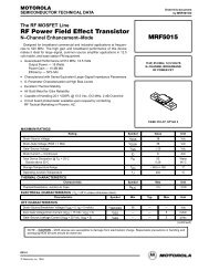
SEMICONDUCTOR<br />
<strong>HFA3101</strong><br />
July 1995<br />
Features<br />
• High Gain Bandwidth Product (f T ) . . . . . . . . . . . 10GHz<br />
• High Power Gain Bandwidth Product . . . . . . . . . 5GHz<br />
• Current Gain (h FE ) . . . . . . . . . . . . . . . . . . . . Typically 70<br />
• Low Noise Figure (Transistor) . . . . . . . . . . . . . . . 3.5dB<br />
• Excellent h FE and V BE Matching<br />
• Low Collector Leakage Current . . . . . . . . . . . .
Absolute Maximum Ratings<br />
V CEO , Collector to Emitter Voltage . . . . . . . . . . . . . . . . . . . . . . . 8.0V<br />
V CBO , Collector to Base Voltage . . . . . . . . . . . . . . . . . . . . . . . 12.0V<br />
V EBO , Emitter to Base Voltage . . . . . . . . . . . . . . . . . . . . . . . . . . 5.5V<br />
I C , Collector Current . . . . . . . . . . . . . . . . . . . . . . . . . . . . . . . . . 30mA<br />
T STG , Storage Temperature Range . . . . . . . . . . . . -65 o C to +150 o C<br />
Operating Temperature Range. . . . . . . . . . . . . . . . . -40 o C to +85 o C<br />
T J , Junction Temperature (DIE) . . . . . . . . . . . . . . . . . . . . . . +175 o C<br />
T J , Junction Temperature (Plastic Package) . . . . . . . . . . . . +150 o C<br />
Lead Temperature (Soldering 10s) (Lead Tips Only) . . . . . . +300 o C<br />
Specifications <strong>HFA3101</strong><br />
Thermal Information<br />
Thermal Resistance<br />
θ JA<br />
Plastic 8 Lead SOIC Package . . . . . . . . . . . . . . . . . . . 185 o C/W<br />
Maximum Package Power Dissipation at +75 o C<br />
Plastic 8 Lead SOIC Package . . . . . . . . . . . . . . . . . . . . . . . . 0.4W<br />
Derating Factor Above +75 o C<br />
Plastic 8 Lead SOIC Package . . . . . . . . . . . . . . . . . . . . 5.4mW/ o C<br />
CAUTION: Stresses above those listed in “Absolute Maximum Ratings” may cause permanent damage to the device. This is a stress only rating and operation<br />
of the device at these or any other conditions above those indicated in the operational sections of this specification is not implied.<br />
Electrical Specifications<br />
at +25 o C<br />
PARAMETER<br />
Collector-to-Base Breakdown Voltage, V (BR)CBO ,<br />
Q1 thru Q6<br />
Collector-to-Emitter Breakdown Voltage, V (BR)CEO ,<br />
Q5 and Q6<br />
Emitter-to-Base Breakdown Voltage, V (BR)EBO ,<br />
Q1 thru Q6<br />
TEST CONDITIONS<br />
(NOTE 1)<br />
TEST<br />
LEVEL<br />
ALL GRADES<br />
MIN TYP MAX<br />
UNITS<br />
I C = 100µA, I E = 0 A 12 18 - V<br />
I C = 100µA, I B = 0 A 8 12 - V<br />
I E = 10µA, I C = 0 A 5.5 6 - V<br />
Collector Cutoff Current, I CBO , Q1 thru Q4 V CB = 8V, I E = 0 A - 0.1 10 nA<br />
Emitter Cutoff Current, I EBO , Q5 and Q6 V EB = 1V, I C = 0 A - - 200 nA<br />
DC Current Gain, h FE , Q1 thru Q6 I C = 10mA, V CE = 3V A 40 70 -<br />
Collector-to-Base Capacitance, C CB Q1 thru Q4 V CB = 5V, f = 1MHz C - 0.300 - pF<br />
Q5 and Q6 - 0.600 - pF<br />
Emitter-to-Base Capacitance, C EB Q1 thru Q4 V EB = 0, f = 1MHz B - 0.200 - pF<br />
Q5 and Q6 - 0.400 - pF<br />
Current Gain-Bandwidth Product, f T Q1 thru Q4 I C = 10mA, V CE = 5V C - 10 - GHz<br />
Q5 and Q6 I C = 20mA, V CE = 5V C - 10 - GHz<br />
Power Gain-Bandwidth Product, f MAX Q1 thru Q4 I C = 10mA, V CE = 5V C - 5 - GHz<br />
Q5 and Q6 I C = 20mA, V CE = 5V C - 5 - GHz<br />
Available Gain at Minimum Noise Figure, G NFMIN ,<br />
Q5 and Q6<br />
Minimum Noise Figure, NF MIN , Q5 and Q6<br />
50Ω Noise Figure, NF 50Ω , Q5 and Q6<br />
DC Current Gain Matching, h FE1 /h FE2 , Q1 and Q2,<br />
Q3 and Q4, and Q5 and Q6<br />
Input Offset Voltage, V OS , (Q1 and Q2), (Q3 and Q4),<br />
(Q5 and Q6)<br />
Input Offset Current, I C , (Q1 and Q2), (Q3 and Q4),<br />
(Q5 and Q6)<br />
Input Offset Voltage TC, dV OS /dT, (Q1 and Q2, Q3 and<br />
Q4, Q5 and Q6)<br />
I C = 5mA,<br />
V CE = 3<br />
I C = 5mA,<br />
V CE = 3V<br />
I C = 5mA,<br />
V CE = 3V<br />
f = 0.5GHz C - 17.5 - dB<br />
f = 1.0GHz C - 11.9 - dB<br />
f = 0.5GHz C - 1.7 - dB<br />
f = 1.0GHz C - 2.0 - dB<br />
f = 0.5GHz C - 2.25 - dB<br />
f = 1.0GHz C - 2.5 - dB<br />
V CE = 3V, I C = 10mA A 0.9 1.0 1.1<br />
I C = 10mA, V CE = 3V A - 1.5 5 mV<br />
I C = 10mA, V CE = 3V A - 5 25 µA<br />
I C = 10mA, V CE = 3V C - 0.5 - µV/ o C<br />
Collector-to-Collector Leakage, I TRENCH-LEAKAGE ∆V TEST = 5V B - 0.01 - nA<br />
NOTE:<br />
1. Test Level: A. Production Tested, B. Guaranteed Limit or Typical Based on Characterization, C. Design Typical for Information Only.<br />
9-27
<strong>HFA3101</strong><br />
PSPICE Model for a 3µm x 50µm Transistor<br />
+ (IS = 1.840E-16 XTI = 3.000E+00 EG = 1.110E+00 VAF = 7.200E+01<br />
+ VAR = 4.500E+00 BF = 1.036E+02 ISE = 1.686E-19 NE = 1.400E+00<br />
+ IKF = 5.400E-02 XTB = 0.000E+00 BR = 1.000E+01 ISC = 1.605E-14<br />
+ NC = 1.800E+00 IKR = 5.400E-02 RC = 1.140E+01 CJC = 3.980E-13<br />
+ MJC = 2.400E-01 VJC = 9.700E-01 FC = 5.000E-01 CJE = 2.400E-13<br />
+ MJE = 5.100E-01 VJE = 8.690E-01 TR = 4.000E-09 TF = 10.51E-12<br />
+ ITF = 3.500E-02 XTF = 2.300E+00 VTF = 3.500E+00 PTF = 0.000E+00<br />
+ XCJC = 9.000E-01 CJS = 1.689E-13 VJS = 9.982E-01 MJS = 0.000E+00<br />
+ RE = 1.848E+00 RB = 5.007E+01 RBM = 1.974E+00 KF = 0.000E+00<br />
+ AF = 1.000E+00)<br />
Common Emitter S-Parameters of 3µm x 50µm Transistor<br />
FREQ. (Hz) |S11| PHASE(S11) |S12| PHASE(S12) |S21| PHASE(S21) |S22| PHASE(S22)<br />
V CE = 5V and I C = 5mA<br />
1.0E+08 0.83 -11.78 1.41E-02 78.88 11.07 168.57 0.97 -11.05<br />
2.0E+08 0.79 -22.82 2.69E-02 68.63 10.51 157.89 0.93 -21.35<br />
3.0E+08 0.73 -32.64 3.75E-02 59.58 9.75 148.44 0.86 -30.44<br />
4.0E+08 0.67 -41.08 4.57E-02 51.90 8.91 140.36 0.79 -38.16<br />
5.0E+08 0.61 -48.23 5.19E-02 45.50 8.10 133.56 0.73 -44.59<br />
6.0E+08 0.55 -54.27 5.65E-02 40.21 7.35 127.88 0.67 -49.93<br />
7.0E+08 0.50 -59.41 6.00E-02 35.82 6.69 123.10 0.62 -54.37<br />
8.0E+08 0.46 -63.81 6.27E-02 32.15 6.11 119.04 0.57 -58.10<br />
9.0E+08 0.42 -67.63 6.47E-02 29.07 5.61 115.57 0.53 -61.25<br />
1.0E+09 0.39 -70.98 6.63E-02 26.45 5.17 112.55 0.50 -63.96<br />
1.1E+09 0.36 -73.95 6.75E-02 24.19 4.79 109.91 0.47 -66.31<br />
1.2E+09 0.34 -76.62 6.85E-02 22.24 4.45 107.57 0.45 -68.37<br />
1.3E+09 0.32 -79.04 6.93E-02 20.53 4.15 105.47 0.43 -70.19<br />
1.4E+09 0.30 -81.25 7.00E-02 19.02 3.89 103.57 0.41 -71.83<br />
1.5E+09 0.28 -83.28 7.05E-02 17.69 3.66 101.84 0.40 -73.31<br />
1.6E+09 0.27 -85.17 7.10E-02 16.49 3.45 100.26 0.39 -74.66<br />
1.7E+09 0.25 -86.92 7.13E-02 15.41 3.27 98.79 0.38 -75.90<br />
1.8E+09 0.24 -88.57 7.17E-02 14.43 3.10 97.43 0.37 -77.05<br />
1.9E+09 0.23 -90.12 7.19E-02 13.54 2.94 96.15 0.36 -78.12<br />
2.0E+09 0.22 -91.59 7.21E-02 12.73 2.80 94.95 0.35 -79.13<br />
2.1E+09 0.21 -92.98 7.23E-02 11.98 2.68 93.81 0.35 -80.09<br />
2.2E+09 0.20 -94.30 7.25E-02 11.29 2.56 92.73 0.34 -80.99<br />
2.3E+09 0.20 -95.57 7.27E-02 10.64 2.45 91.70 0.34 -81.85<br />
2.4E+09 0.19 -96.78 7.28E-02 10.05 2.35 90.72 0.33 -82.68<br />
2.5E+09 0.18 -97.93 7.29E-02 9.49 2.26 89.78 0.33 -83.47<br />
2.6E+09 0.18 -99.05 7.30E-02 8.96 2.18 88.87 0.33 -84.23<br />
9-28
<strong>HFA3101</strong><br />
Common Emitter S-Parameters of 3µm x 50µm Transistor (Continued)<br />
FREQ. (Hz) |S11| PHASE(S11) |S12| PHASE(S12) |S21| PHASE(S21) |S22| PHASE(S22)<br />
2.7E+09 0.17 -100.12 7.31E-02 8.47 2.10 88.00 0.33 -84.97<br />
2.8E+09 0.17 -101.15 7.31E-02 8.01 2.02 87.15 0.33 -85.68<br />
2.9E+09 0.16 -102.15 7.32E-02 7.57 1.96 86.33 0.33 -86.37<br />
3.0E+09 0.16 -103.11 7.32E-02 7.16 1.89 85.54 0.33 -87.05<br />
V CE = 5V and I C = 10mA<br />
1.0E+08 0.72 -16.43 1.27E-02 75.41 15.12 165.22 0.95 -14.26<br />
2.0E+08 0.67 -31.26 2.34E-02 62.89 13.90 152.04 0.88 -26.95<br />
3.0E+08 0.60 -43.76 3.13E-02 52.58 12.39 141.18 0.79 -37.31<br />
4.0E+08 0.53 -54.00 3.68E-02 44.50 10.92 132.57 0.70 -45.45<br />
5.0E+08 0.47 -62.38 4.05E-02 38.23 9.62 125.78 0.63 -51.77<br />
6.0E+08 0.42 -69.35 4.31E-02 33.34 8.53 120.37 0.57 -56.72<br />
7.0E+08 0.37 -75.26 4.49E-02 29.47 7.62 116.00 0.51 -60.65<br />
8.0E+08 0.34 -80.36 4.63E-02 26.37 6.86 112.39 0.47 -63.85<br />
9.0E+08 0.31 -84.84 4.72E-02 23.84 6.22 109.36 0.44 -66.49<br />
1.0E+09 0.29 -88.83 4.80E-02 21.75 5.69 106.77 0.41 -68.71<br />
1.1E+09 0.27 -92.44 4.86E-02 20.00 5.23 104.51 0.39 -70.62<br />
1.2E+09 0.25 -95.73 4.90E-02 18.52 4.83 102.53 0.37 -72.28<br />
1.3E+09 0.24 -98.75 4.94E-02 17.25 4.49 100.75 0.35 -73.76<br />
1.4E+09 0.22 -101.55 4.97E-02 16.15 4.19 99.16 0.34 -75.08<br />
1.5E+09 0.21 -104.15 4.99E-02 15.19 3.93 97.70 0.33 -76.28<br />
1.6E+09 0.20 -106.57 5.01E-02 14.34 3.70 96.36 0.32 -77.38<br />
1.7E+09 0.20 -108.85 5.03E-02 13.60 3.49 95.12 0.31 -78.41<br />
1.8E+09 0.19 -110.98 5.05E-02 12.94 3.30 93.96 0.31 -79.37<br />
1.9E+09 0.18 -113.00 5.06E-02 12.34 3.13 92.87 0.30 -80.27<br />
2.0E+09 0.18 -114.90 5.07E-02 11.81 2.98 91.85 0.30 -81.13<br />
2.1E+09 0.17 -116.69 5.08E-02 11.33 2.84 90.87 0.30 -81.95<br />
2.2E+09 0.17 -118.39 5.09E-02 10.89 2.72 89.94 0.29 -82.74<br />
2.3E+09 0.16 -120.01 5.10E-02 10.50 2.60 89.06 0.29 -83.50<br />
2.4E+09 0.16 -121.54 5.11E-02 10.13 2.49 88.21 0.29 -84.24<br />
2.5E+09 0.16 -122.99 5.12E-02 9.80 2.39 87.39 0.29 -84.95<br />
2.6E+09 0.15 -124.37 5.12E-02 9.49 2.30 86.60 0.29 -85.64<br />
2.7E+09 0.15 -125.69 5.13E-02 9.21 2.22 85.83 0.29 -86.32<br />
2.8E+09 0.15 -126.94 5.13E-02 8.95 2.14 85.09 0.29 -86.98<br />
2.9E+09 0.15 -128.14 5.14E-02 8.71 2.06 84.36 0.29 -87.62<br />
3.0E+09 0.14 -129.27 5.15E-02 8.49 1.99 83.66 0.29 -88.25<br />
9-29
<strong>HFA3101</strong><br />
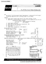
Typical Performance Curves for Transistors<br />
I C (A)<br />
x 10 -3<br />
70<br />
60<br />
50<br />
40<br />
30<br />
20<br />
10<br />
Ib = 200µ<br />
Ib = 800µ<br />
Ib = 400µ<br />
Ib. = 1m<br />
Ib = 600µ<br />
0<br />
0 2.0 4.0<br />
6.0<br />
V CE (V)<br />
h FE<br />
V CE = 5<br />
140<br />
120<br />
100<br />
80<br />
60<br />
40<br />
20<br />
0<br />
10 -10 10 -8 10 -6 10 -4 10 -2 10 0<br />
I C (A)<br />
FIGURE 1. I C vs V CE<br />
FIGURE 2. H FE vs I C<br />
10 0<br />
10 -2<br />
V CE = 3<br />
x 10 9<br />
12<br />
10<br />
10 -4<br />
8<br />
I C & I B (A)<br />
10 -6<br />
10 -8<br />
f T (Hz)<br />
6<br />
4<br />
10 -10<br />
2<br />
10 -12 0.20 0.40 0.60 0.80 1.0<br />
V BE (V)<br />
0<br />
10 -4 10 -3 10 -2 10 -1<br />
I C (A)<br />
FIGURE 3. GUMMEL PLOT<br />
FIGURE 4. F T vs I C<br />
4.8<br />
20<br />
NOISE FIGURE (dB)<br />
4.6<br />
4.4<br />
4.2<br />
4.0<br />
3.8<br />
3.6<br />
3.4<br />
18<br />
16<br />
14<br />
12<br />
10<br />
6<br />
|S 21 | (dB)<br />
NOTE: Figures 14 through 18 are only for Q5 and Q6.<br />
3.2<br />
4<br />
0 0.5 1.0 1.5 2.0 2.5 3.0<br />
FREQUENCY (GHz)<br />
FIGURE 5. GAIN AND NOISE FIGURE vs FREQUENCY<br />
9-30
<strong>HFA3101</strong><br />
Die Characteristics<br />
PROCESS<br />
UHF-1<br />
DIE DIMENSIONS:<br />
53 x 52 x 14 ± 1mils<br />
1340µm x 1320µm x 355.6µm ± 25.4µm<br />
METALLIZATION:<br />
Type: Metal 1: AlCu(2%)/TiW<br />
Thickness: Metal 1: 8kÅ ± 0.5kÅ<br />
GLASSIVATION:<br />
Type: Nitride<br />
Thickness: 4kÅ ± 0.5kÅ<br />
DIE ATTACH:<br />
Material: Epoxy<br />
WORST CASE CURRENT DENSITY:<br />
1.3636 x 10 5 A/cm 2<br />
Type: Metal 2: AlCu(2%)<br />
Thickness: Metal 2: 16kÅ ± 0.8kÅ<br />
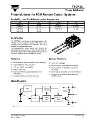
Metallization Mask Layout<br />
<strong>HFA3101</strong><br />
7<br />
7<br />
6<br />
6<br />
8<br />
5<br />
8<br />
5<br />
1<br />
4<br />
1<br />
4<br />
2 2 3 3<br />
9-31
<strong>HFA3101</strong><br />
Application Information<br />
The <strong>HFA3101</strong> array is a very versatile RF Building block. It<br />
has been carefully laid out to improve its matching properties,<br />
bringing the distortion due to area mismatches, thermal distribution,<br />
betas and ohmic resistances to a minimum.<br />
The cell is equivalent to two differential stages built as two<br />
“variable transconductance multipliers” in parallel, with their<br />
outputs cross coupled. This configuration is well known in the<br />
industry as a Gilbert Cell which enables a four quadrant multiplication<br />
operation.<br />
Due to the input dynamic range restrictions for the input levels<br />
at the upper quad transistors and lower tail transistors, the<br />
<strong>HFA3101</strong> cell has restricted use as a linear four quadrant<br />
multiplier. However, its configuration is well suited for uses<br />
where its linear response is limited to one of the inputs only,<br />
as in modulators or mixer circuit applications. Examples of<br />
these circuits are up converters, down converters, frequency<br />
doublers and frequency/phase detectors.<br />
Although linearization is still an issue for the lower pair input,<br />
emitter degeneration can be used to improve the dynamic<br />
range and consequent linearity. The <strong>HFA3101</strong> has the lower<br />
pair emitters brought to external pins for this purpose.<br />
In modulators applications, the upper quad transistors are<br />
used in a switching mode where the pairs Q1/Q2 and Q3/Q4<br />
act as non saturating high speed switches. These switches<br />
are controlled by the signal often referred as the carrier input.<br />
The signal driving the lower pair Q5/Q6 is commonly used as<br />
the modulating input. This signal can be linearly transferred<br />
to the output by either the use of low signal levels (Well below<br />
the thermal voltage of 26mV) or by the use of emitter degeneration.<br />
The chopped waveform appearing at the output of<br />
the upper pair (Q1 to Q4) resembles a signal that is multiplied<br />
by +1 or -1 at every half cycle of the switching waveform.<br />
CARRIER SIGNAL<br />
+1<br />
Figure 6 shows the typical input waveforms where the frequency<br />
of the carrier is higher than the modulating signal.<br />
The output waveform shows a typical suppressed carrier output<br />
of an up converter or an AM signal generator.<br />
Carrier suppression capability is a property of the well known<br />
Balanced modulator in which the output must be zero when<br />
one or the other input (carrier or modulating signal) is equal to<br />
zero. however, at very high frequencies, high frequency mismatches<br />
and AC offsets are always present and the suppression<br />
capability is often degraded causing carrier and<br />
modulating feedthrough to be present.<br />
Being a frequency translation circuit, the balanced modulator<br />
has the properties of translating the modulating frequency<br />
(ω M ) to the carrier frequency (ω C ), generating the two side<br />
bands ω U = ω C + ω M and ω L = ω C - ω M . Figure 7 shows some<br />
translating schemes being used by balanced mixers.<br />
ω C - ω M<br />
FIGURE 7A. UP CONVERSION OR SUPPRESSED CARRIER AM<br />
IF (ω C - ω M )<br />
FOLDED BACK<br />
ω C<br />
ω C<br />
ω C + ω M<br />
ω M<br />
-1<br />
MODULATING SIGNAL<br />
FIGURE 7B. DOWN CONVERSION<br />
ω C<br />
BASEBAND<br />
DIFFERENTIAL OUTPUT<br />
ω M<br />
FIGURE 7C. ZERO IF OR DIRECT DOWN CONVERSION<br />
FIGURE 6. TYPICAL MODULATOR SIGNALS<br />
FIGURE 7. MODULATOR FREQUENCY SPECT<strong>RU</strong>M<br />
9-32
<strong>HFA3101</strong><br />
The use of the <strong>HFA3101</strong> as modulators has several advantages<br />
when compared to its counterpart, the diode doublebalanced<br />
mixer, in which it is required to receive enough<br />
energy to drive the diodes into a switching mode and has<br />
also some requirements depending on the frequency range<br />
desired, of different transformers to suit specific frequency<br />
responses. The <strong>HFA3101</strong> requires very low driving capabilities<br />
for its carrier input and its frequency response is limited<br />
by the F T of the devices, the design and the layout techniques<br />
being utilized.<br />
Up conversion uses, for UHF transmitters for example, can be<br />
performed by injecting a modulating input in the range of<br />
45MHz to 130MHz that carries the information often called IF<br />
(Intermediate frequency) for up conversion (The IF signal has<br />
been previously modulated by some modulation scheme from<br />
a baseband signal of audio or digital information) and by injecting<br />
the signal of a local oscillator of a much higher frequency<br />
range from 600MHz to 1.2GHz into the carrier input. Using the<br />
example of a 850MHz carrier input and a 70MHz IF, the output<br />
spectrum will contain a upper side band of 920MHz, a lower<br />
side band of 780MHz and some of the carrier (850MHz) and IF<br />
(70MHz) feedthrough. A Band pass filter at the output can<br />
attenuate the undesirable signals and the 920MHz signal can<br />
be routed to a transmitter RF power amplifier.<br />
Down conversion, as the name implies, is the process used<br />
to translate a higher frequency signal to a lower frequency<br />
range conserving the modulation information contained in<br />
the higher frequency signal. One very common typical down<br />
conversion use for example, is for superheterodyne radio<br />
receivers where a translated lower frequency often referred<br />
as intermediate frequency (IF) is used for detection or<br />
demodulation of the baseband signal. Other application uses<br />
include down conversion for special filtering using frequency<br />
translation methods.<br />
An oscillator referred as the local oscillator (LO) drives the<br />
upper quad transistors of the cell with a frequency called<br />
ω C . The lower pair is driven by the RF signal of frequency<br />
ω M to be translated to a lower frequency IF. The spectrum of<br />
the IF output will contain the sum and difference of the frequencies<br />
ω C and ω M . Notice that the difference can become<br />
negative when the frequency of the local oscillator is lower<br />
than the incoming frequency and the signal is folded back as<br />
in Figure 7.<br />
NOTE: The acronyms RF, IF and LO are often interchanged in the<br />
industry depending on the application of the cell as mixers or<br />
modulators. The output of the cell also contains multiples of the<br />
frequency of the signal being fed to the upper quad pair of transistors<br />
because of the switching action equivalent to a square wave<br />
multiplication. In practice, however, not only the odd multiples in the<br />
case of a symmetrical square wave but some of the even multiples<br />
will also appear at the output spectrum due to the nature of the actual<br />
switching waveform and high frequency performance. By-products of<br />
the form M*ω C + N*ω M with M and N being positive or negative<br />
integers are also expected to be present at the output and their levels<br />
are carefully examined and minimized by the design. This distortion<br />
is considered one of the figures of merit for a mixer application.<br />
The process of frequency doubling is also understood by<br />
having the same signal being fed to both modulating and<br />
carrier ports. The output frequency will be the sum of ω C and<br />
ω M which is equivalent to the product of the input frequency<br />
by 2 and a zero Hz or DC frequency equivalent to the difference<br />
of ω C and ω M . Figure 7 also shows one technique in<br />
use today where a process of down conversion named zero<br />
IF is made by using a local oscillator with a very pure signal<br />
frequency equal to the incoming RF frequency signal that<br />
contains a baseband (audio or digital signal) modulation.<br />
Although complex, the extraction or detection of the signal is<br />
straightforward.<br />
Another useful application of the <strong>HFA3101</strong> is its use as a<br />
high frequency phase detector where the two signals are fed<br />
to the carrier and modulation ports and the DC information is<br />
extracted from its output. In this case, both ports are utilized<br />
in a switching mode or overdrive, such that the process of<br />
multiplication takes place in a quasi digital form (2 square<br />
waves). One application of a phase detector is frequency or<br />
phase demodulation where the FM signal is split before the<br />
modulating and carrier ports. The lower input port is always<br />
90 degrees apart from the carrier input signal through a high<br />
Q tuned phase shift network. The network, being tuned for a<br />
precise 90 degrees shift at a nominal frequency, will set the<br />
two signals 90 degrees apart and a quiescent output DC level<br />
will be present at the output. When the input signal is frequency<br />
modulated, the phase shift of the signal coming from<br />
the network will deviate from 90 degrees proportional to the<br />
frequency deviation of the FM signal and a DC variation at<br />
the output will take place, resembling the demodulated FM<br />
signal.<br />
The <strong>HFA3101</strong> could also be used for quadrature detection,<br />
(I/Q demodulation), AGC control with limited range, low level<br />
multiplication to name a few other applications.<br />
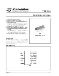
Biasing<br />
Various biasing schemes can be employed for use with the<br />
<strong>HFA3101</strong>. Figure 8 shows the most common schemes. The<br />
biasing method is a choice of the designer when cost, thermal<br />
dependence, voltage overheads and DC balancing<br />
properties are taken into consideration.<br />
Figure 8A shows the simplest form of biasing the <strong>HFA3101</strong>.<br />
The current source required for the lower pair is set by the<br />
voltage across the resistor R BIAS less a V BE drop of the lower<br />
transistor. To increase the overhead, collector resistors are<br />
substituted by a RF choke as the upper pair functions as a<br />
current source for AC signals. The bases of the upper and<br />
lower transistors are biased by RB1 and RB2 respectively.<br />
The voltage drop across the resistor R2 must be higher than<br />
a V BE with an increase sufficient to assure that the collector to<br />
base junctions of the lower pair are always reverse biased.<br />
Notice that this same voltage also sets the V CE of operation of<br />
the lower pair which is important for the optimization of gain.<br />
Resistors R EE are nominally zero for applications where the<br />
input signals are well below 25mV peak. Resistors R EE are<br />
used to increase the linearity of the circuit upon higher level<br />
signals. The drop across R EE must be taken into consideration<br />
when setting the current source value.<br />
Figure 8B depicts the use of a common resistor sharing the<br />
current through the cell which is used for temperature compensation<br />
as the lower pair V BE drop at the rate of -2mV/ o C.<br />
Figure 8C uses a split supply.<br />
9-33
<strong>HFA3101</strong><br />
V CC<br />
V CC<br />
R C<br />
V CC<br />
R1<br />
RB1<br />
L CH<br />
R1<br />
RB1<br />
L CH<br />
R1<br />
RB1<br />
L CH<br />
R2<br />
1<br />
2<br />
3<br />
4<br />
8<br />
7<br />
6<br />
5<br />
Q1 Q2<br />
Q3 Q4<br />
Q5<br />
Q6<br />
R2<br />
1<br />
2<br />
3<br />
4<br />
8<br />
7<br />
6<br />
5<br />
Q1 Q2<br />
Q3 Q4<br />
Q5<br />
Q6<br />
1<br />
2<br />
3<br />
4<br />
8<br />
7<br />
6<br />
5<br />
R2<br />
Q1 Q2<br />
Q3 Q4<br />
Q5<br />
Q6<br />
R BIAS<br />
R EE<br />
RB2<br />
R E<br />
R EE<br />
R BIAS<br />
R EE<br />
RB2<br />
R E<br />
R EE<br />
R BIAS<br />
R EE<br />
RB2<br />
R E<br />
R EE<br />
V EE<br />
FIGURE 8A. FIGURE 8B. FIGURE 8C.<br />
FIGURE 8.<br />
Design Example: Down Converter Mixer<br />
Figure 9 shows an example of a low cost mixer for cellular<br />
applications.<br />
LO IN<br />
0.01<br />
0.01<br />
0.01<br />
0.01<br />
825MHz<br />
V CC<br />
110<br />
330<br />
220<br />
51<br />
8<br />
1<br />
7<br />
Q1 Q2<br />
Q5<br />
2<br />
6<br />
3<br />
V EE<br />
27<br />
L CH<br />
390nH<br />
FIGURE 9. 3V DOWN CONVERTER APPLICATION<br />
The design flexibility of the <strong>HFA3101</strong> is demonstrated by a<br />
low cost, and low voltage mixer application at the 900MHz<br />
range. The choice of good quality chip components with their<br />
self resonance outside the boundaries of the application are<br />
important. The design has been optimized to accommodate<br />
Q6<br />
5<br />
Q3 Q4<br />
4<br />
51<br />
2K<br />
5p TO 12p<br />
0.01<br />
0.1<br />
V CC<br />
3V<br />
IF OUT<br />
75MHz<br />
R F IN<br />
900MHz<br />
the evaluation of the same layout for various quiescent current<br />
values and lower supply voltages. The choice of R E<br />
became important for the available overhead and also for<br />
maintaining an AC true impedance for high frequency signals.<br />
The value of 27Ω has been found to be the optimum<br />
minimum for the application. The input impedances of the<br />
<strong>HFA3101</strong> base input ports are high enough to permit their<br />
termination with 50Ω resistors. Notice the AC termination by<br />
decoupling the bias circuit through good quality capacitors.<br />
The choice of the bias has been related to the available<br />
power supply voltage with the values of R1, R2 and R BIAS<br />
splitting the voltages for optimum V CE values. For evaluation<br />
of the cell quiescent currents, the voltage at the emitter<br />
resistor R E has been recorded.<br />
The gain of the circuit, being a function of the load and the<br />
combined emitter resistances at high frequencies have been<br />
kept to a maximum by the use of an output match network.<br />
The high output impedance of the <strong>HFA3101</strong> permits broadband<br />
match if so desired at 50Ω (R L = 50Ω to 2kΩ) as well<br />
as with tuned medium Q matching networks (L, T etc.).<br />
Stability<br />
The cell, by its nature, has very high gain and precautions<br />
must be taken to account for the combination of signal<br />
reflections, gain, layout and package parasitics. The rule of<br />
thumb of avoiding reflected waves must be observed. It is<br />
important to assure good matching between the mixer stage<br />
and its front end. Laboratory measurements have shown<br />
some susceptibility for oscillation at the upper quad transistors<br />
input. Any LO prefiltering has to be designed such the<br />
return loss is maintained within acceptable limits specially at<br />
high frequencies. Typical off the shelf filters exhibits very<br />
9-34
<strong>HFA3101</strong><br />
poor return loss for signals outside the passband. It is suggested<br />
that a “pad” or a broadband resistive network be<br />
used to interface the LO port with a filter. The inclusion of a<br />
parallel 2K resistor in the load decreases the gain slightly<br />
which improves the stability factor and also improves the distortion<br />
products (output intermodulation or 3rd order intercept).<br />
The employment of good RF techniques shall suffice<br />
the stability requirements.<br />
Evaluation<br />
The evaluation of the <strong>HFA3101</strong> in a mixer configuration is<br />
presented in Figures 11 to Figure 16, Table 1 and Table 2. The<br />
layout is depicted in Figure 10.<br />
TABLE 2. S22 PARAMETERS FOR DOWN CONVERSION,<br />
L CH = 10µH<br />
PARAMETER LO LEVEL<br />
V CC = 3V<br />
I BIAS = 8mA<br />
Power Gain -6dBm 8.5dB<br />
TOI Output -6dBm 11.5dBm<br />
NF SSB -6dBm 14.5dB<br />
Power Gain 0dBm 8.6dB<br />
TOI Output 0dBm 11dBm<br />
NF SSB 0dBm 15dB<br />
PARAMETER LO LEVEL<br />
V CC = 4V<br />
I BIAS = 19mA<br />
Power Gain -6dBm 10dB<br />
TOI Output -6dBm 13dBm<br />
NF SSB -6dBm 20dB<br />
Power Gain 0dBm 11dB<br />
TOI Output 0dBm 12.5dBm<br />
NF SSB 0dBm 24dB<br />
TABLE 3. TYPICAL VALUES OF S22 FOR THE OUTPUT PORT.<br />
L CH = 390nH I BIAS = 8mA (SET UP OF FIGURE 11)<br />
FREQUENCY RESISTANCE REACTANCE<br />
300MHz 22Ω -115Ω<br />
600MHz 7.5Ω -43Ω<br />
900MHz 5.2Ω -14Ω<br />
1.1GHz 3.9Ω 0Ω<br />
TABLE 4. TYPICAL VALUES OF S22. L CH = 390nH, I BIAS = 18mA<br />
FREQUENCY RESISTANCE REACTANCE<br />
300MHz 23.5Ω -110Ω<br />
600MHz 10.3Ω -39Ω<br />
FIGURE 10. UP/DOWN CONVERTER LAYOUT, 400%.<br />
MATERIAL G10, 0.031<br />
The output matching network has been designed from data<br />
taken at the output port at various test frequencies with the<br />
setup as in Table 1. S22 characterization is enough to assure<br />
the calculation of L, T or transmission line matching networks.<br />
TABLE 1. S22 PARAMETERS FOR DOWN CONVERSION,<br />
L CH = 10µH<br />
FREQUENCY RESISTANCE REACTANCE<br />
10MHz 265Ω 615Ω<br />
45MHz 420Ω - 735Ω<br />
75MHz 122Ω - 432Ω<br />
100MHz 67Ω - 320Ω<br />
900MHz 8.7Ω -14Ω<br />
1.1GHz 8Ω 0Ω<br />
Up Converter Example<br />
An application for a up converter as well as a frequency multiplier<br />
can be demonstrated using the same layout, with an<br />
addition of matching components. The output port S22 must<br />
be characterized for proper matching procedures and<br />
depending on the frequency desired for the output, transmission<br />
line transformations can be designed. The return loss of<br />
the input ports maintain acceptable values in excess of<br />
1.2GHz which can permit the evaluation of a frequency doubler<br />
to 2.4GHz if so desired.<br />
The addition of the resistors R EE can increase considerably<br />
the dynamic range of the up converter as demonstrated at<br />
Figure 18. The evaluation results depicted in Table 5 have<br />
been obtained by a triple stub tuner as a matching network<br />
for the output due to the layout constraints. Based on the<br />
evaluation results it is clear that the cell requires a higher<br />
Bias current for overall performance.<br />
9-35
<strong>HFA3101</strong><br />
L CH<br />
2K<br />
V CC 3V<br />
0.1<br />
0dB<br />
5dB/DIV<br />
S11 LOG MAG<br />
4V<br />
8<br />
7<br />
6<br />
5<br />
3V<br />
Q1 Q2<br />
Q5<br />
Q3 Q4<br />
Q6<br />
1<br />
2<br />
3<br />
4<br />
100MHz<br />
1.1GHz<br />
FIGURE 11. OUTPUT PORT S22 TEST SET UP<br />
FIGURE 12. LO PORT RETURN LOSS<br />
0dB<br />
10dB/DIV<br />
S11 LOG MAG<br />
0dB<br />
5dB/DIV<br />
S22 LOG MAG<br />
100MHz<br />
1.1GHz<br />
10MHz<br />
110MHz<br />
FIGURE 13. RF PORT RETURN LOSS<br />
FIGURE 14. IF PORT RETURN LOSS, WITH MATCHING<br />
NETWORK<br />
10dB/<br />
DIV<br />
R F = 901MHz - 25dBm<br />
LO = 825MHz -6dBm<br />
-17dBm<br />
10dB/<br />
DIV<br />
R F = 900MHz -25dBm<br />
LO = 825MHz -6dBm<br />
-26dBm<br />
-36dBm<br />
-53dBm<br />
64M<br />
11<br />
* LO - 10R F<br />
76MHz<br />
IF<br />
88M<br />
12R F - 13LO<br />
SPAN<br />
40MHz<br />
-58dBm<br />
675 750 825 900 975<br />
LO - 2R F<br />
LO + 2R F<br />
SPAN<br />
500MHz<br />
FIGURE 15. TYPICAL IN BAND OUTPUT SPECT<strong>RU</strong>M, V CC = 3V<br />
FIGURE 16. TYPICAL OUT OF BAND OUTPUT SPECT<strong>RU</strong>M<br />
9-36
<strong>HFA3101</strong><br />
Design Example: Up Converter Mixer<br />
Figure 17 shows an example of a up converter for cellular<br />
applications.<br />
Conclusion<br />
The <strong>HFA3101</strong> offers the designer a number of choices and<br />
different applications as a powerful RF building block.<br />
Although isolation is degraded from the theoretical results<br />
for the cell due to the unbalanced, nondifferential input<br />
schemes being used, a number of advantages can be taken<br />
into consideration like cost, flexibility, low power and small<br />
outline when deciding for a design.<br />
TABLE 5. TYPICAL PARAMETERS FOR AN UP CONVERTER<br />
EXAMPLE<br />
PARAMETER<br />
V CC = 3V<br />
I BIAS = 8mA<br />
V CC = 4V<br />
I BIAS = 18mA<br />
Power Gain, LO = -6dBm 3dB 5.5dBm<br />
Power Gain, LO = 0dBm 4dB 7.2dB<br />
R F Isolation, LO = 0dBm 15dBc 22dBc<br />
LO Isolation, LO = 0dBm 28dBc 28dBc<br />
V CC 3V<br />
LO IN<br />
0.01<br />
825MHz<br />
V CC 3V<br />
51<br />
8<br />
7<br />
6<br />
5<br />
390nH<br />
0.01<br />
0.1<br />
5.2nH<br />
11p<br />
900MHz<br />
0.01<br />
110<br />
Q1 Q2<br />
Q3 Q4<br />
0.01<br />
330<br />
1<br />
Q5<br />
2<br />
3<br />
Q6<br />
4<br />
0.01<br />
R F IN<br />
75MHz<br />
R EE R EE<br />
51<br />
0.01<br />
220<br />
27<br />
FIGURE 17.<br />
OUTPUT WITHOUT EMITTER DEGENERATION<br />
OUTPUT WITH EMITTER DEGENERATION R EE = 4.7Ω<br />
EXPANDED SPECT<strong>RU</strong>M R EE = 4.7Ω<br />
890<br />
2LO - 10R F<br />
901 912<br />
12R F<br />
SPAN<br />
50MHz<br />
825 900 976<br />
R F = 76MHz<br />
LO = 825MHz<br />
FIGURE 18. TYPICAL SPECT<strong>RU</strong>M PERFORMANCE<br />
9-37