UHF Power Transistor MRA1000-3.5L - igor
UHF Power Transistor MRA1000-3.5L - igor
UHF Power Transistor MRA1000-3.5L - igor

Create successful ePaper yourself
Turn your PDF publications into a flip-book with our unique Google optimized e-Paper software.
SEMICONDUCTOR TECHNICAL DATA<br />
Order this document<br />
by <strong>MRA1000</strong>–<strong>3.5L</strong>/D<br />
The RF Line<br />
<br />
Designed primarily for wideband, large–signal output and driver amplifier<br />
stages to 1000 MHz.<br />
• Designed for Class A Linear <strong>Power</strong> Amplifiers<br />
• Specified 19 Volt, 1000 MHz Characteristics:<br />
Output <strong>Power</strong> — 3.5 Watts<br />
<strong>Power</strong> Gain — 10 dB, Small–Signal<br />
• Built–In Matching Network for Broadband Operation<br />
• Gold Metallization for Improved Reliability<br />
• Diffused Ballast Resistors<br />
<br />
10 dB, 1000 MHz<br />
3.5 W<br />
BROADBAND<br />
<strong>UHF</strong> POWER TRANSISTOR<br />
MAXIMUM RATINGS<br />
Rating Symbol Value Unit<br />
Collector–Emitter Voltage VCEO 28 Vdc<br />
Collector–Base Voltage VCBO 50 Vdc<br />
Emitter–Base Voltage VEBO 3.5 Vdc<br />
Total Device Dissipation @ TC = 25°C<br />
Derate above 25°C<br />
PD 22<br />
0.125<br />
Operating Junction Temperature TJ 200 °C<br />
Storage Temperature Range Tstg –65 to +200 °C<br />
THERMAL CHARACTERISTICS<br />
Watts<br />
W/°C<br />
Characteristic Symbol Max Unit<br />
Thermal Resistance, Junction to Case (TC = 70°C) RθJC 8 °C/W<br />
ELECTRICAL CHARACTERISTICS<br />
OFF CHARACTERISTICS<br />
CASE 145D–02, STYLE 1<br />
(.380 SOE)<br />
Characteristic Symbol Min Typ Max Unit<br />
Collector–Emitter Breakdown Voltage (IC = 10 mA, IB = 0) V(BR)CEO 28 – – Vdc<br />
Collector–Emitter Breakdown Voltage (IC = 10 mA, VBE = 0) V(BR)CES 50 – – Vdc<br />
Collector–Base Breakdown Voltage (IC = 10 mA, IE = 0) V(BR)CBO 50 – – Vdc<br />
Emitter–Base Breakdown Voltage (IE = 5 mA, IC = 0) V(BR)EBO 3.5 – – Vdc<br />
Collector Cutoff Current (VCB = 30 V, IE = 0) ICBO – – 10 mAdc<br />
. (continued)<br />
REV 1<br />
© MOTOROLA Motorola, Inc. 1997 RF DEVICE DATA<br />
<strong>MRA1000</strong>–<strong>3.5L</strong><br />
1
ELECTRICAL CHARACTERISTICS — continued<br />
ON CHARACTERISTICS<br />
Characteristic Symbol Min Typ Max Unit<br />
DC Current Gain (IC = 250 mA, VCE = 5 V) hFE 20 – 90 –<br />
DYNAMIC CHARACTERISTICS<br />
Output Capacitance (VCB = 24 V, IE = 0, f = 1 MHz) Cob – – 15 pF<br />
FUNCTIONAL TESTS<br />
Common–Emitter Amplifier Small–Signal Gain<br />
(VCE = 19 V, Pin = 1 mW, f = 1 GHz, IC = 600 mA)<br />
GSS 10 – – dB<br />
Load Mismatch<br />
(VCE = 19 V, IC = 600 mA, Pout = 3.5 W, f = 1 GHz,<br />
Load VSWR = ∞:1, All Phase Angles)<br />
ψ<br />
No Degradation in Output <strong>Power</strong><br />
Overdrive (VCE = 19 V, IC = 600 mA, f = 1 GHz)<br />
(No degradation)<br />
Pinover – – 1.75 W<br />
TYPICAL CHARACTERISTICS<br />
Table 1. Common Emitter S–Parameters<br />
VCE<br />
IC<br />
f<br />
S11 S21 S12 S22<br />
(Volts) (mA) (GHz) Mag φ Mag φ Mag φ Mag φ<br />
19 600 0.5 0.91 174 1.78 53 0.03 23 0.55 –164<br />
0.6 0.9 173 1.64 47 0.03 21 0.58 –170<br />
0.7 0.87 171 1.53 36 0.03 19 0.63 –159<br />
0.8 0.85 168 1.51 24 0.03 15 0.68 –157<br />
0.9 0.82 168 1.49 10 0.03 5 0.74 –158<br />
1 0.78 168 1.5 –7 0.03 –4 0.83 –160<br />
Table 2. Zin and ZOL* versus Frequency<br />
VCC = 19 V, Pc = 3.5 W<br />
Freq.<br />
ZOL* Zin (Ohms)<br />
(MHz) Re Im Re Im<br />
500 14.6 –6.31 2.36 2.53<br />
600 13.2 –4.07 2.74 3.18<br />
700 11.7 –8.95 3.36 4.14<br />
800 9.95 –9.65 4.12 5.13<br />
900 7.72 –9.72 4.99 5.33<br />
1000 4.67 –8.74 6.36 5.04<br />
ZOL* = Conjugate of the optimum lead impedance into which the device output operates at a given frequency, output power and voltage.<br />
<strong>MRA1000</strong>–<strong>3.5L</strong><br />
2<br />
MOTOROLA RF DEVICE DATA
0.8 1.0<br />
0.6<br />
1.5<br />
2.0<br />
0.4<br />
3.0<br />
4.0<br />
0.2<br />
5.0<br />
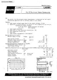
Zin<br />
Zo = 50 Ω<br />
800 900<br />
10<br />
700<br />
f = 1000 MHz<br />
600<br />
0.2<br />
0 500<br />
0.4 0.6 0.8 1.0 1.5 2.0 3.0 4.0 5.0 10<br />
600<br />
700<br />
f = 500 MHz<br />
1000<br />
10<br />
900 800<br />
0.2<br />
5.0<br />
ZOL*<br />
4.0<br />
Pout, OUTPUT POWER (WATTS)<br />
7.0<br />
6.0<br />
5.0<br />
4.0<br />
3.0<br />
2.0<br />
1.0<br />
0.4<br />
0.6<br />
1.5<br />
0.8 1.0<br />
VCC = 19 V, Po = 3.5 W, Zo = 50 Ω<br />
2.0<br />
3.0<br />
0<br />
0<br />
100 200 300 400 500 600 700 800 900 1000<br />
Pin, INPUT POWER (mW)<br />
Figure 2. <strong>Power</strong> Input versus <strong>Power</strong> Output<br />
Figure 1. Series Equivalent Input/Output Impedance<br />
VBIAS<br />
RF IN<br />
C1<br />
C2<br />
L1<br />
R1<br />
L2<br />
L3<br />
L4<br />
VCC = 19 Vdc<br />
+<br />
C6 C7 C8 C9<br />
Z1 Z2 Z5 Z6<br />
Z3<br />
Z4<br />
C3<br />
R2<br />
C4<br />
C5<br />
RF<br />
OUT<br />
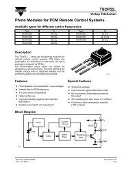
C1, C3, C5, C6, C7 500 pF, ATC<br />
C2, C4 0.8 – 10 pF, JFD<br />
C9<br />
0.1 µF, 50 V, Ceramic<br />
L1<br />
7T, 20 Gauge on 200 Mil Ferrite Toroid<br />
L2<br />
8T, 20 Gauge, 100 Mil Dia.<br />
L3<br />
11T, 20 Gauge, 100 Mil Dia.<br />
L4<br />
8T, 20 Gauge on 275 Mil Ferrite Toroid<br />
R1, R2 15 Ω, 1/4 Watt<br />
Z1<br />
50 Ω, Microstripline, 4 = 0.110 λ<br />
Z2<br />
10 Ω, Microstripline, 4 = 0.162 λ<br />
Z3, Z4 50 Ω, Microstripline, 4 = 0.052 λ<br />
Z5<br />
24 Ω, Microstripline, 4 = 0.080 λ<br />
Z6<br />
50 Ω, Microstripline, 4 = 0.125 λ<br />
Figure 3. 1 GHz Test Circuit<br />
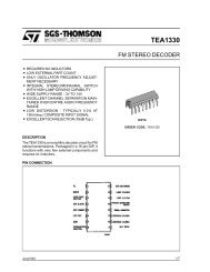
1.0 kΩ<br />
VSUPPLY = 21.6 Vdc<br />
VSUPPLY<br />
3 x 11 Ω<br />
2N2222<br />
5 W<br />
VCC<br />
TIP41<br />
4.7 kΩ<br />
2.7 kΩ<br />
180 Ω<br />
4.7 Ω<br />
68 Ω<br />
VBIAS<br />
Figure 4. Bias Circuit<br />
MOTOROLA RF DEVICE DATA<br />
<strong>MRA1000</strong>–<strong>3.5L</strong><br />
3
PACKAGE DIMENSIONS<br />
C<br />
R<br />
8–32UNC–2A<br />
W<br />
A<br />
2<br />
V<br />
J<br />
D<br />
H<br />
NOTES:<br />
1. DIMENSIONING AND TOLERANCING PER ANSI<br />
Y14.5M, 1982.<br />
2. CONTROLLING DIMENSION: INCH.<br />
INCHES MILLIMETERS<br />
DIM MIN MAX MIN MAX<br />
A 0.320 0.385 9.28 9.77<br />
B 0.320 0.330 8.13 8.38<br />
C 0.700 0.778 17.78 19.76<br />
D 0.220 0.230 5.59 5.84<br />
H 0.160 0.170 4.07 4.31<br />
J 0.003 0.006 0.08 0.15<br />
K 0.490 0.520 12.45 13.20<br />
R 0.248 0.275 6.30 7.23<br />
V 0.100 0.130 2.54 3.30<br />
W 0.055 0.065 1.40 1.65<br />
B 1<br />
3<br />
4<br />
K<br />
STYLE 1:<br />
PIN 1. EMITTER<br />
2. BASE<br />
3. EMITTER<br />
4. COLLECTOR<br />
CASE 145D–02<br />
ISSUE A<br />
Motorola reserves the right to make changes without further notice to any products herein. Motorola makes no warranty, representation or guarantee regarding<br />
the suitability of its products for any particular purpose, nor does Motorola assume any liability arising out of the application or use of any product or circuit, and<br />
specifically disclaims any and all liability, including without limitation consequential or incidental damages. “Typical” parameters which may be provided in Motorola<br />
data sheets and/or specifications can and do vary in different applications and actual performance may vary over time. All operating parameters, including “Typicals”<br />
must be validated for each customer application by customer’s technical experts. Motorola does not convey any license under its patent rights nor the rights of<br />
others. Motorola products are not designed, intended, or authorized for use as components in systems intended for surgical implant into the body, or other<br />
applications intended to support or sustain life, or for any other application in which the failure of the Motorola product could create a situation where personal injury<br />
or death may occur. Should Buyer purchase or use Motorola products for any such unintended or unauthorized application, Buyer shall indemnify and hold Motorola<br />
and its officers, employees, subsidiaries, affiliates, and distributors harmless against all claims, costs, damages, and expenses, and reasonable attorney fees<br />
arising out of, directly or indirectly, any claim of personal injury or death associated with such unintended or unauthorized use, even if such claim alleges that<br />
Motorola was negligent regarding the design or manufacture of the part. Motorola and are registered trademarks of Motorola, Inc. Motorola, Inc. is an Equal<br />
Opportunity/Affirmative Action Employer.<br />
Mfax is a trademark of Motorola, Inc.<br />
How to reach us:<br />
USA / EUROPE / Locations Not Listed: Motorola Literature Distribution; JAPAN: Nippon Motorola Ltd.: SPD, Strategic Planning Office, 4–32–1,<br />
P.O. Box 5405, Denver, Colorado 80217. 1–303–675–2140 or 1–800–441–2447 Nishi–Gotanda, Shinagawa–ku, Tokyo 141, Japan. 81–3–5487–8488<br />
Mfax: RMFAX0@email.sps.mot.com – TOUCHTONE 1–602–244–6609 ASIA/PACIFIC: Motorola Semiconductors H.K. Ltd.; 8B Tai Ping Industrial Park,<br />
– US & Canada ONLY 1–800–774–1848 51 Ting Kok Road, Tai Po, N.T., Hong Kong. 852–26629298<br />
– http://sps.motorola.com/mfax<br />
INTERNET: http://motorola.com/sps<br />
<strong>MRA1000</strong>–<strong>3.5L</strong><br />
4<br />
◊<br />
MOTOROLA RF DEVICE <strong>MRA1000</strong>–<strong>3.5L</strong>/D DATA