energize oil & gas – issue 01-2013 - GL Group
energize oil & gas – issue 01-2013 - GL Group
energize oil & gas – issue 01-2013 - GL Group

You also want an ePaper? Increase the reach of your titles
YUMPU automatically turns print PDFs into web optimized ePapers that Google loves.
provides a factor to increase repair thickness when applied<br />
to a bend, however this is not included in the FEA for conservatism.<br />
The repair method in ISO 24817 then states that the<br />
actual repair thickness shall be determined by dividing this<br />
calculated thickness by the individual layer or wrap thickness.<br />
The required number of wraps of the repair shall be<br />
this number rounded up to the next integer. The actual repair<br />
thickness shall be the number of wraps times the individual<br />
wrap thickness. For conservatism, the FEA uses the<br />
minimum calculated repair thickness.<br />
LPF ( = applied pressure in MPa)<br />
30<br />
25<br />
20<br />
15<br />
10<br />
5<br />
0<br />
Limit pressures for corroded bends<br />
(80 % depth of min. WT)<br />
600 NB thin, D/Tb=53.5<br />
300 NB thin, D/Tb=45.6<br />
1,200 NB, D/Tb=52.3<br />
900 NB, D/Tb=48.4<br />
600 NB thick, D/Tb=35.9<br />
300 NB, D/Tb=28.4<br />
150 NB, D/Tb=20.0<br />
50 NB, D/Tb=12.6<br />
0 5 10 15 20 25 30<br />
Y Displacement at bend intrados {mm}<br />
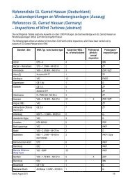
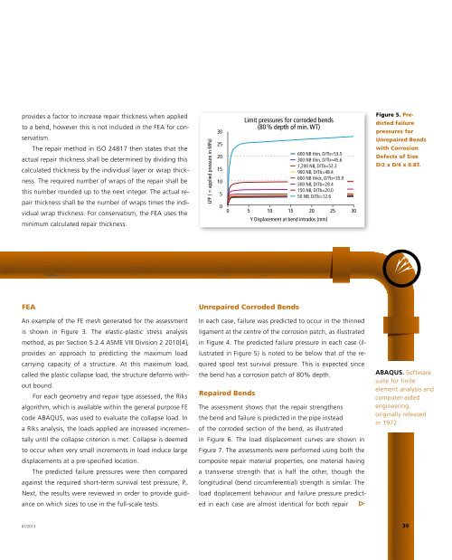
Figure 5. Predicted<br />
failure<br />
pressures for<br />
Unrepaired Bends<br />
with Corrosion<br />
Defects of Size<br />
D/2 x D/4 x 0.8T.<br />
FEA<br />
An example of the FE mesh generated for the assessment<br />
is shown in Figure 3. The elastic-plastic stress analysis<br />
method, as per Section 5.2.4 ASME VIII Division 2 2<strong>01</strong>0[4],<br />
provides an approach to predicting the maximum load<br />
carrying capacity of a structure. At this maximum load,<br />
called the plastic collapse load, the structure deforms without<br />
bound.<br />
For each geometry and repair type assessed, the Riks<br />
algorithm, which is available within the general purpose FE<br />
code ABAQUS, was used to evaluate the collapse load. In<br />
a Riks analysis, the loads applied are increased incrementally<br />
until the collapse criterion is met. Collapse is deemed<br />
to occur when very small increments in load induce large<br />
displacements at a pre-specified location.<br />
The predicted failure pressures were then compared<br />
against the required short-term survival test pressure, P f .<br />
Next, the results were reviewed in order to provide guidance<br />
on which sizes to use in the full-scale tests.<br />
Unrepaired Corroded Bends<br />
In each case, failure was predicted to occur in the thinned<br />
ligament at the centre of the corrosion patch, as illustrated<br />
in Figure 4. The predicted failure pressure in each case (illustrated<br />
in Figure 5) is noted to be below that of the required<br />
spool test survival pressure. This is expected since<br />
the bend has a corrosion patch of 80% depth.<br />
Repaired Bends<br />
The assessment shows that the repair strengthens<br />
the bend and failure is predicted in the pipe instead<br />
of the corroded section of the bend, as illustrated<br />
in Figure 6. The load displacement curves are shown in<br />
Figure 7. The assessments were performed using both the<br />
composite repair material properties, one material having<br />
a transverse strength that is half the other, though the<br />
longitudinal (bend circumferential) strength is similar. The<br />
load displacement behaviour and failure pressure predicted<br />
in each case are almost identical for both repair<br />
ABAQUS. Software<br />
suite for finite<br />
element analysis and<br />
computer-aided<br />
engineering,<br />
originally released<br />
in 1972.<br />
<strong>01</strong>/2<strong>01</strong>3<br />
39