The IGES, DXF and STEP Exchange Formats IGES IGES ... - CAE
The IGES, DXF and STEP Exchange Formats IGES IGES ... - CAE
The IGES, DXF and STEP Exchange Formats IGES IGES ... - CAE
You also want an ePaper? Increase the reach of your titles
YUMPU automatically turns print PDFs into web optimized ePapers that Google loves.
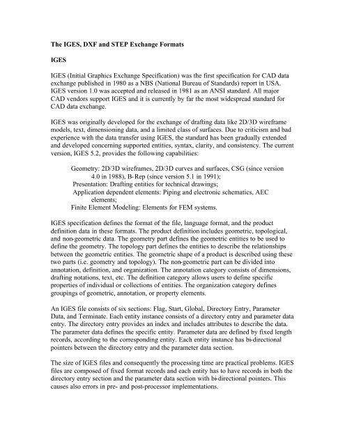
<strong>The</strong> <strong>IGES</strong>, <strong>DXF</strong> <strong>and</strong> <strong>STEP</strong> <strong>Exchange</strong> <strong>Formats</strong><br />
<strong>IGES</strong><br />
<strong>IGES</strong> (Initial Graphics <strong>Exchange</strong> Specification) was the first specification for CAD data<br />
exchange published in 1980 as a NBS (National Bureau of St<strong>and</strong>ards) report in USA.<br />
<strong>IGES</strong> version 1.0 was accepted <strong>and</strong> released in 1981 as an ANSI st<strong>and</strong>ard. All major<br />
CAD vendors support <strong>IGES</strong> <strong>and</strong> it is currently by far the most widespread st<strong>and</strong>ard for<br />
CAD data exchange.<br />
<strong>IGES</strong> was originally developed for the exchange of drafting data like 2D/3D wireframe<br />
models, text, dimensioning data, <strong>and</strong> a limited class of surfaces. Due to criticism <strong>and</strong> bad<br />
experience with the data transfer using <strong>IGES</strong>, the st<strong>and</strong>ard has been gradually extended<br />
<strong>and</strong> developed concerning supported entities, syntax, clarity, <strong>and</strong> consistency. <strong>The</strong> current<br />
version, <strong>IGES</strong> 5.2, provides the following capabilities:<br />
Geometry: 2D/3D wireframes, 2D/3D curves <strong>and</strong> surfaces, CSG (since version<br />
4.0 in 1988), B-Rep (since version 5.1 in 1991);<br />
Presentation: Drafting entities for technical drawings;<br />
Application dependent elements: Piping <strong>and</strong> electronic schematics, AEC<br />
elements;<br />
Finite Element Modeling: Elements for FEM systems.<br />
<strong>IGES</strong> specification defines the format of the file, language format, <strong>and</strong> the product<br />
definition data in these formats. <strong>The</strong> product definition includes geometric, topological,<br />
<strong>and</strong> non-geometric data. <strong>The</strong> geometry part defines the geometric entities to be used to<br />
define the geometry. <strong>The</strong> topology part defines the entities to describe the relationships<br />
between the geometric entities. <strong>The</strong> geometric shape of a product is described using these<br />
two parts (i.e. geometry <strong>and</strong> topology). <strong>The</strong> non-geometric part can be divided into<br />
annotation, definition, <strong>and</strong> organization. <strong>The</strong> annotation category consists of dimensions,<br />
drafting notations, text, etc. <strong>The</strong> definition category allows users to define specific<br />
properties of individual or collections of entities. <strong>The</strong> organization category defines<br />
groupings of geometric, annotation, or property elements.<br />
An <strong>IGES</strong> file consists of six sections: Flag, Start, Global, Directory Entry, Parameter<br />
Data, <strong>and</strong> Terminate. Each entity instance consists of a directory entry <strong>and</strong> parameter data<br />
entry. <strong>The</strong> directory entry provides an index <strong>and</strong> includes attributes to describe the data.<br />
<strong>The</strong> parameter data defines the specific entity. Parameter data are defined by fixed length<br />
records, according to the corresponding entity. Each entity instance has bi-directional<br />
pointers between the directory entry <strong>and</strong> the parameter data section.<br />
<strong>The</strong> size of <strong>IGES</strong> files <strong>and</strong> consequently the processing time are practical problems. <strong>IGES</strong><br />
files are composed of fixed format records <strong>and</strong> each entity has to have records in both the<br />
directory entry section <strong>and</strong> the parameter data section with bi-directional pointers. This<br />
causes also errors in pre- <strong>and</strong> post-processor implementations.
<strong>IGES</strong> is under control of the NCGA (National Computer Graphics Association) <strong>and</strong> is<br />
part of the U.S. Product Data Association (USPRO) <strong>and</strong> the <strong>IGES</strong>/PDES Organization<br />
(IGO). <strong>The</strong> NCGA administers the National <strong>IGES</strong> User Group (NIUG), which provides<br />
access to information on <strong>IGES</strong>.<br />
<strong>DXF</strong><br />
<strong>DXF</strong> (Data eXchange Format) was originally developed by Autodesk, Inc., the vendor of<br />
AutoCAD. It has become a "de-facto" st<strong>and</strong>ard among most CAD vendors <strong>and</strong> is in wide<br />
use to exchange 2D/3D wireframe data. All implementations of AutoCAD accept this<br />
format <strong>and</strong> are able to convert it to <strong>and</strong> from their internal representation. A <strong>DXF</strong> file is a<br />
complete representation of the AutoCAD drawing database thus some features or<br />
concepts can't be used by other CAD systems. <strong>The</strong> <strong>DXF</strong> version R13 supports wireframe,<br />
surface, <strong>and</strong> solid representations.<br />
A <strong>DXF</strong> file consists of four sections: Header, Table, Block, <strong>and</strong> Entity section. <strong>The</strong><br />
header section contains general information about the drawing. Each parameter has a<br />
variable name <strong>and</strong> an associated value. <strong>The</strong> table section contains definitions of line<br />
types, layers, text styles, views, etc. <strong>The</strong> block section contains entities for block<br />
definitions. <strong>The</strong>se entities define the blocks used in the drawing. <strong>The</strong> format of the<br />
entities in the block section is identical to entities in the entity section. <strong>The</strong> entity section<br />
contains the drawing entities, including any block references. Items in the entity section<br />
exist also in the block section <strong>and</strong> the appearance of entities in the two sections is<br />
identical.<br />
Variables, table entries, <strong>and</strong> entities are described by a group that introduces the item,<br />
giving its type <strong>and</strong>/or name, followed by multiple groups that supply the values<br />
associated with the item. In addition, special groups are used for separators such as<br />
markers for the beginning <strong>and</strong> end of sections, tables, <strong>and</strong> the file itself. Group codes are<br />
used to describe the type of the value, <strong>and</strong> the general use of the group.<br />
<strong>STEP</strong><br />
<strong>STEP</strong> (ST<strong>and</strong>ard for the <strong>Exchange</strong> of Product model data) is a new International<br />
St<strong>and</strong>ard (ISO 10303) for representing <strong>and</strong> exchanging product model information. It<br />
includes an object-flavored data specification language, EXPRESS, to describe the<br />
representation of the data. <strong>STEP</strong> defines also implementation methods, for instance, a<br />
physical transfer file, <strong>and</strong> offers different resources, e.g. geometric <strong>and</strong> topological<br />
representation.<br />
<strong>The</strong> development of <strong>STEP</strong> started in 1984 as a worldwide collaboration. <strong>The</strong> goal was to<br />
define a st<strong>and</strong>ard to cover all aspects of a product (i.e. geometry, topology, tolerances,<br />
materials, etc.), during its lifetime. This kind of attempt was not been made before. <strong>STEP</strong><br />
is a collection of st<strong>and</strong>ards to represent <strong>and</strong> exchange product information. <strong>The</strong> main<br />
parts of <strong>STEP</strong> are already international st<strong>and</strong>ards, while many parts are still under<br />
development. <strong>The</strong> development is performed under the control of the International
St<strong>and</strong>ards organization (ISO), Technical Committee 184 (TC184, Industrial Automation<br />
Systems), Subcommittee 4 (SC4, Industrial Data <strong>and</strong> Global Manufacturing<br />
Programming Languages).<br />
<strong>The</strong> objective of <strong>STEP</strong> is to offer system-independent mechanism to describe the product<br />
information in computer aided systems throughout its lifetime. It separates the<br />
representation of product information from the implementation methods.<br />
Implementation methods are used for data exchange. <strong>The</strong> representation offers a<br />
definition of product information to many applications. <strong>STEP</strong> provides also a basis for<br />
archiving product information <strong>and</strong> a methodology for the conformance testing of<br />
implementations.<br />
EXPRESS is a formal data specification language used to specify the representation of<br />
product information. <strong>The</strong> use of a formal data specification language facilitates<br />
development of implementation. It also enables consistency of representation.<br />
<strong>STEP</strong> specifies the implementation methods used for data exchange that support the<br />
representation of product information.<br />
<strong>STEP</strong> does not only define the geometric shape of a product: it also includes topology,<br />
features, tolerance specifications, material properties, etc. necessary to completely define<br />
a product for the purposes of design, analysis, manufacture, test, inspection <strong>and</strong> product<br />
support. <strong>The</strong> use of <strong>STEP</strong> is still very modest but it is growing all the time. <strong>The</strong> majority<br />
of CAD system vendors has implemented or is implementing <strong>STEP</strong> pre- <strong>and</strong> postprocessors<br />
for their CAD systems. <strong>STEP</strong> is an evolving st<strong>and</strong>ard that will cover the<br />
whole product life cycle in terms of data sharing, storage <strong>and</strong> exchange. It is the most<br />
important <strong>and</strong> largest effort ever established in engineering domain <strong>and</strong> will replace<br />
current CAD exchange st<strong>and</strong>ards.


