2003 LSSV Operator Manual Supplement (PDF) - GM Fleet
2003 LSSV Operator Manual Supplement (PDF) - GM Fleet
2003 LSSV Operator Manual Supplement (PDF) - GM Fleet

You also want an ePaper? Increase the reach of your titles
YUMPU automatically turns print PDFs into web optimized ePapers that Google loves.
<strong>2003</strong> General Motors Light Service Support Vehicle (<strong>LSSV</strong>)<br />
Military Truck Owner’s <strong>Manual</strong> <strong>Supplement</strong><br />
Seats and Restraints Systems........................................1-1<br />
Troop Seats...................................................................1-2<br />
Restraints........................................................................1-3<br />
Features and Controls........................................................2-1<br />
Windows..........................................................................2-2<br />
Starting and Operating the Vehicle...........................2-3<br />
Fuel Fired Coolant Heater..........................................2-4<br />
Storage Areas................................................................2-5<br />
Cargo Tie Downs........................................................2-7<br />
Weapons Mount............................................................2-7<br />
Instrument Panel..................................................................3-1<br />
Exterior Lamps..............................................................3-2<br />
Interior Lamps.......................................................3-6<br />
Warning Lights, Gages and Indicators....................3-8<br />
Driving The Vehicle............................................................4-1<br />
Your Driving, the Road and the Vehicle..................4-2<br />
Towing..............................................................................4-8<br />
Service and Appearance Care.........................................5-1<br />
Underhood Component Locator...............................5-2<br />
Vent Filters.....................................................................5-10<br />
Replacement Bulbs.....................................................5-11<br />
Tires.................................................................................5-11<br />
Appearance Care.........................................................5-12<br />
Vehicle Information.......................................................5-13<br />
Electrical System..........................................................5-14<br />
Maintenance Schedule.......................................................6-1<br />
Maintenance Schedule................................................6-2<br />
Customer Assistance Information..................................7-1<br />
Customer Assistance Information............................7-2<br />
Index........................................................................................8-1<br />
i
The information in this manual pertains to the operation<br />
of the vehicle. It also contains the vehicle’s scheduled<br />
maintenance services. This manual along with the<br />
owner’s manual will assist you in the proper use and<br />
maintenance of the vehicle. The sections in this<br />
supplement correspond to the sections in the <strong>2003</strong> Vehicle<br />
Owner’s <strong>Manual</strong> and the <strong>2003</strong> Duramax Diesel Engine<br />
Owner’s <strong>Manual</strong> <strong>Supplement</strong>.<br />
Please keep this supplement with the owner’s manual<br />
and diesel supplement in the vehicle, so it will be there<br />
if you ever need it while you’re on the road.<br />
This manual includes the latest information at the time<br />
it was printed. We reserve the right to make changes in<br />
the product after that time without notice.<br />
How to Use This <strong>Manual</strong><br />
Many people read the owner’s manual from beginning to<br />
end when they first receive the vehicle. If you do this, it<br />
will help you learn about the features and controls for the<br />
vehicle. In this manual, you’ll find that pictures and<br />
words work together to explain things.<br />
Litho in USA<br />
Part No. <strong>LSSV</strong>OM03 First Edition<br />
ii<br />
©<br />
Copyright General Motors Corporation 10/01/04<br />
All Rights Reserved.
Index<br />
A good place to look for what you need is the Index in<br />
back of the manual. It’s an alphabetical list of what’s in<br />
the manual, and the page number where you’ll find it.<br />
Driving the Vehicle<br />
As with other vehicles of this type, failure to operate this<br />
vehicle correctly may result in loss of control or an<br />
accident. Refer to “The Driving, the Road and the Vehicle”<br />
and “Off-Road Driving with The Four-Wheel-Drive Vehicle”<br />
in the <strong>2003</strong> Vehicle Owner’s <strong>Manual</strong>.<br />
Safety Warnings and Symbols<br />
You will find a number of safety cautions in this book. We<br />
use a box and the word CAUTION to tell you about things<br />
that could cause personal injury if you were to ignore the<br />
warning.<br />
CAUTION:<br />
These mean there is something that could hurt you<br />
or other people.<br />
In the caution area, we tell you what the hazard is. Then<br />
we tell you what to do to help avoid or reduce the hazard.<br />
Please read these cautions. If you don’t, you or others<br />
could be hurt.<br />
Vehicle Damage Warnings<br />
Also, in this supplement manual you will find these<br />
notices:<br />
Notice: These mean there is something that<br />
could damage the vehicle.<br />
In the notice area, we tell you about something that can<br />
damage the vehicle. Many times, this damage would not<br />
be covered by the warranty, and it could be costly. But the<br />
notice will tell you what to do to help avoid the damage.<br />
When you read other manuals, you might see CAUTION<br />
and NOTICE warnings in different colors or in different<br />
words.<br />
You’ll also see warning labels on the vehicle.<br />
They use the same words, CAUTION or NOTICE.<br />
iii
NOTES<br />
iv
Section 1 Seats and Restraints<br />
Troop Seats...........................................................................1-2<br />
Folding the Seat Down...............................................1-2<br />
Folding the Seat Up.....................................................1-3<br />
Restraints...............................................................................1-3<br />
Rear Safety Strap.........................................................1-3<br />
1-1
Troop Seats<br />
If the vehicle is equipped with troop seats, this feature<br />
provides space for up to eight passengers in the cargo<br />
area of the pickup model. The seats can be lowered<br />
individually for use or raised for storage. The seats lock<br />
in both the up and down positions.<br />
Troop Seat Operation<br />
When the seat is in the up position, the quick release pin<br />
will go through the left-hand leg for passenger’s side<br />
seats or a right-hand leg for driver’s side seats. It will<br />
then go through the seat channel and will be placed in<br />
front of the hinge pin.<br />
Folding the Seat Down<br />
15363<br />
1-2<br />
9556<br />
A quick-release pin is located on the left or right side of the<br />
troop seat leg immediately under the hinge pin.<br />
1. Remove the pin and place the legs into the joint<br />
of the cargo area side and the floor.
Restraints<br />
Rear Safety Strap<br />
9557<br />
2. Place the pin in the hole provided under the hinge<br />
pin. The seat is now locked in the down position.<br />
Folding the Seat Up<br />
Reverse Steps 1 and 2.<br />
9559<br />
Whenever the troop seats are occupied, the safety strap<br />
should be attached across the top of the rear seat backs<br />
using the eye-bolts provided.<br />
To remove the troop seats, refer to Seats in the <strong>2003</strong><br />
<strong>LSSV</strong> Military Trucks service manual supplement.<br />
1-3
NOTES<br />
1-4
Section 2 Features and Controls<br />
Windows.................................................................................2-2<br />
Rear Topper Window...................................................2-2<br />
Side Topper Window...................................................2-2<br />
Sliding Rear Window...................................................2-3<br />
Starting and Operating the Vehicle..................................2-3<br />
Starting The Engine....................................................2-3<br />
Fuel Fired Coolant Heater..................................................2-4<br />
Fuel Fired Coolant Heater Operation.....................2-4<br />
Storage Areas.......................................................................2-5<br />
Cargo Cover-Soft Top..................................................2-5<br />
Rolling Up the Side Panels.......................................2-5<br />
Storing the Cargo Cover..............................................2-5<br />
Cargo Tie Downs.................................................................2-7<br />
Weapons Mount...................................................................2-7<br />
Weapons Mount (Floor Mount)..................................2-7<br />
Weapons Mount (Cab Mount)...................................2-8<br />
2-1
Windows<br />
If the vehicle is equipped with a topper, it features<br />
tempered opening windows that have locking handles.<br />
Rear Topper Window<br />
Notice: The window must be fully closed before<br />
operation of the vehicle.<br />
Side Topper Window<br />
Opening the Rear Window Door<br />
1. Turn both handles (A) clockwise 90°.<br />
2. Pull open the rear window door. A cylinder on both<br />
sides of the window will assist with opening and<br />
hold the window in the open position.<br />
Closing Rear Window Door<br />
1. Pull the window door down.<br />
2. Turn both handles (A) counter clockwise 90°.<br />
2-2<br />
10317<br />
Open the Side Window Doors<br />
1. Turn both handles (A) clockwise 90°.<br />
2. Pull open the window door. A cylinder on both sides<br />
of the window will assist with opening and hold<br />
the window in the open position.<br />
Closing the Side Window Doors<br />
10316<br />
1. Pull the window door down.<br />
2. Turn both handles (A) counter clockwise 90°.<br />
Notice: The window must be fully closed before<br />
operation of the vehicle.
Sliding Rear Window<br />
If the vehicle is equipped with a sliding rear window, it<br />
features tempered glass surrounded by a durable black<br />
finish aluminum frame and three panel design. Locking<br />
latch adds cab security.<br />
To open the window hold the latch in the open position<br />
and slide the window open. To close the window slide<br />
the window until the latch is fully engaged against the<br />
frame.<br />
Starting and Operating the<br />
Vehicle<br />
Starting the Engine<br />
The diesel engine starts differently than a gasoline<br />
engine.<br />
CAUTION:<br />
Do not use gasoline or starting “aids,” such as ether,<br />
in the air intake. They could damage the engine. There<br />
could also be a fire, which could cause serious<br />
personal injury.<br />
Refer to the 2004 Duramax Diesel Engine Owner’s<br />
<strong>Manual</strong> <strong>Supplement</strong>, located in the glove compartment.<br />
15030<br />
2-3
Fuel Fired Coolant Heater<br />
CAUTION:<br />
To Prevent Asphyxiation: DO NOT operate while<br />
in confined spaces such as closed, unventilated<br />
enclosures! Open an outside enclosure door before<br />
operating the heater.<br />
To Prevent Fire: DO NOT operate heater where<br />
flammable or explosive materials, gases or dusts<br />
may be present. DO NOT operate heater over dry<br />
grass or other dry ground cover. Switch heater off<br />
while refueling vehicle! Switch heater off<br />
BEFORE entering fueling stations!<br />
To Prevent Burning: NEVER touch hot components<br />
of the heating system!<br />
The heater is a diesel powered supplementary<br />
heating system that will heat the engine coolant of<br />
the vehicle. This will prevent cold start up of the<br />
engine. It can be used in conjunction with the factory<br />
coolant heater.<br />
Fuel Fired Coolant Heater Operation<br />
13718<br />
The fuel fired coolant heater<br />
is controlled by a toggle<br />
switch located on the<br />
instrument panel (I/P) bezel<br />
to the left of the steering<br />
column. The heater is<br />
activated by moving the<br />
switch (A) to the ON<br />
position.<br />
An indicator lamp will illuminate the switch. To deactivate<br />
the heater move the switch to the OFF position.<br />
If the switch is in the ON position and flashing, there is<br />
a problem with the system. Refer to the <strong>2003</strong> <strong>LSSV</strong><br />
Service <strong>Manual</strong> Military <strong>Supplement</strong>.<br />
Turn the fuel fired coolant heater OFF when not in use.<br />
2-4
Storage Areas<br />
Cargo Cover-Soft Top<br />
If the vehicle is equipped with a soft top cargo cover, it<br />
must be fully installed and properly anchored before<br />
traveling on the highway. The side panels and rear panel<br />
of the cargo cover can be rolled up. The cargo cover<br />
allows ventilation within the closed portion through<br />
opening vents located on the front of the top.<br />
Rolling Up the Side Panels:<br />
9560<br />
1. Release tension on the<br />
hooks by pushing the<br />
release on the front of the<br />
hook.<br />
2. Remove the plastic hook<br />
from the bed fastener.<br />
3. Pull apart the velcro flaps<br />
on both side panels near<br />
the vehicle cab.<br />
6. When the sides reach the top, they can be held in<br />
place by inserting the cargo cover straps in the clips<br />
at the top of the cargo cover.<br />
Storing the Cargo Cover:<br />
1. Release tension on the hooks by pushing the<br />
release on the front of the hook.<br />
2. Remove the plastic hook from the bed fastener.<br />
3. Pull apart the velcro flaps on both side panels near<br />
the vehicle cab.<br />
4. Pull apart the velcro flaps on both panels near<br />
the back of the vehicle.<br />
5. Release the six cover straps, located inside the<br />
cargo box that attaches the cover to the cargo cover<br />
bows.<br />
6. Remove the cover from the cargo cover bows.<br />
7. Fold the cover neatly and store it behind the seat in<br />
the truck cab.<br />
4. Pull apart the velcro flaps on both side panels near<br />
the back of the vehicle.<br />
5. Roll the sides upward.<br />
2-5
8. Release the four corner<br />
support straps.<br />
10. Stack the bows on top of each other without<br />
striking the cab or the troop seats (if equipped),<br />
push down equally on both sides of the upper part<br />
of the front and rear bows.<br />
11. Pull upward equally on both sides of the upper part<br />
of the center bow.<br />
12. Standing at the rear of the vehicle, push the bows<br />
forward.<br />
15338<br />
9563<br />
13. Secure the bows in place with the front support straps.<br />
2-6<br />
9562<br />
9. Remove the six quick release pins from the sides of<br />
the cargo cover bows.<br />
14. To reinstall the cargo cover, reverse Steps 1 - 13.<br />
Note: The cargo cover is marked with the word FRONT<br />
on the inside top to aid in proper positioning of the cover<br />
onto the vehicle.
Cargo Tie Downs<br />
If the vehicle is equipped with cargo tie downs, four are<br />
provided on each side of the rear cargo area.<br />
CAUTION:<br />
Do not load the vehicle any heavier that the Gross<br />
Vehicle Weight Rating (GVWR), or either the<br />
maximum front or rear Gross Axle Weight Rating<br />
(GAWR). If you do, parts on the vehicle can break,<br />
and it can change the way the vehicle handles.<br />
These could cause you to lose control and crash.<br />
Also, overloading can shorten the life of the vehicle.<br />
Weapons Mount<br />
Weapon Mount (Floor Mount)<br />
14729<br />
The cargo tie downs (A) are used to strap cargo in and<br />
keep it from moving inside the cargo area.<br />
Each of these tie down rings are rated for a maximum<br />
pull of 660 lbs. (300 kg) upward or 450 lbs. (200 kg) of<br />
horizontal force.<br />
CAUTION:<br />
If the weapon is improperly stored, it can move<br />
around in a collision or sudden stop. People in<br />
the vehicle could be injured. Be sure to secure<br />
any such item properly. The weapon should be<br />
made safe when stored in this mount.<br />
The floor mount weapon mount is located behind the<br />
front seats and will secure two weapons.<br />
2-7
Mounting the Weapon<br />
Weapon Mount (Cab Mount)<br />
CAUTION:<br />
If the weapon is improperly stored, it can move<br />
around in a collision or sudden stop. People in<br />
the vehicle could be injured. Be sure to secure<br />
any such item properly. The weapon should be<br />
made safe when stored in this mount.<br />
Lower Weapon Mount<br />
To secure weapons in the vehicle’s mount:<br />
14730<br />
1. Place the stock of the weapon into the lower mount.<br />
1. Place the stock into the<br />
lower weapon mount.<br />
2. Place the barrel into the upper mount until fully seated<br />
in the clamp.<br />
3. Secure with strap and pull to tighten. Pull the strap<br />
outward and slide it over the barrel of the weapon<br />
and secure the buckle by pulling tight.<br />
2-8<br />
6240
Upper Weapon Mount<br />
2. Place the barrel into the<br />
upper weapon mount<br />
until fully seated.<br />
3. Pull the strap outward<br />
and slide it over the<br />
barrel of the weapon<br />
and secure the buckle<br />
by pulling tight.<br />
10458<br />
2-9
NOTES<br />
2-10
Section 3 Instrument Panel<br />
Exterior Lamps.....................................................................3-2<br />
Service and Blackout Lighting...................................3-2<br />
Operating Service and Blackout Lighting................3-4<br />
Interior Lamps......................................................................3-6<br />
Topper Dome Lamp....................................................3-6<br />
Warning Lights, Gages and Indicators...........................3-8<br />
24-Volt Gage...........................................................3-8<br />
3-1
Exterior Lamps<br />
Service and Blackout Lighting<br />
Service Lights/Blackout Control<br />
The switch located on the accessory panel next to the<br />
24-volt gage is the service lights/blackout control.<br />
With the Ignition Switch in the ON Position:<br />
• Pull the switch outward then push upward to the<br />
service ON position. All normal service lamps<br />
will be operational with normal controls.<br />
• Move the service lights/blackout switch to the<br />
center ALL OFF position. All lamps and<br />
accessory power to the vehicle will turn off.<br />
• Move the switch to the blackout position, the<br />
following will occur:<br />
3-2<br />
13870<br />
Notice: If the vehicle is not going to be driven for 24<br />
hours or more, the service lights switch must be placed<br />
in the “ALL OFF” position. This will help prevent drain on<br />
the batteries.<br />
Notice: Before normal driving operations, turn on service<br />
lights to ensure headlights, brake lights and turn signals<br />
are operational.<br />
• The blackout lighting system will be operative.<br />
• The front and rear blackout marker lamps will<br />
illuminate.<br />
• The blackout stop lamps will illuminate when<br />
the brakes are applied.<br />
• The instrument panel warning lights will
emain functional.<br />
• The hazard lights will remain functional.<br />
automatically after you release it from either the<br />
ON or OFF position.<br />
• The horn will not be functional.<br />
The vehicle’s military 12-pin trailer wiring connector<br />
and trailer lamps are also controlled by this switch.<br />
Blackout Drive Light Control<br />
The switch located on the accessory panel next to the<br />
service light switch is the blackout drive light control.<br />
The service lights/blackout control switch must be in<br />
blackout position or in the down position for the blackout<br />
drive lights to function.<br />
With the ignition switch in the ON position:<br />
• Pull the switch outward then up to the ON<br />
position, the front blackout drive lamp will<br />
activate.<br />
• Pull the switch outward then down to the OFF<br />
position, the blackout drive lamp will deactivate.<br />
• The switch will return to the center position<br />
3-3
Operating Service and Blackout Lighting<br />
Exterior Lamp or Device<br />
Headlamps and Taillamps<br />
Parking Lamps<br />
Front/Rear Side Marker Lamps<br />
Marker Lamps; Roof, Fender and End Gate<br />
Stop Lamps<br />
Back-Up Lamps<br />
License Plate Lamps<br />
Front/Rear Turn Signals<br />
Hazard Warning Lamps<br />
Cargo Lamp (If Equipped)<br />
Horn<br />
Front/Rear Blackout Marker Lamps<br />
Blackout Stop Lamps<br />
Blackout Drive Lamp (Headlamp)<br />
Service Lights/Blackout Switch<br />
SERVICE ON<br />
SERVICE ON<br />
SERVICE ON<br />
SERVICE ON<br />
SERVICE ON<br />
SERVICE ON<br />
SERVICE ON<br />
SERVICE ON<br />
SERVICE ON<br />
SERVICE ON<br />
SERVICE ON<br />
BLACKOUT<br />
BLACKOUT<br />
BLACKOUT<br />
Blackout Drive Light Switch<br />
OFF<br />
OFF<br />
OFF<br />
OFF<br />
OFF<br />
OFF<br />
OFF<br />
OFF<br />
ON/OFF<br />
OFF<br />
OFF<br />
ON/OFF<br />
ON/OFF<br />
ON<br />
3-4
Exterior Lamp or Device<br />
Instrument Panel/Switch Illumination<br />
Radio/Clock Illumination<br />
Headlamp High-Beam Indicator<br />
Turn Signal/Hazard Warning Indicators<br />
Four-Wheel-Drive Indicator<br />
Dome/Courtesy Lamps<br />
Glove Compartment Lamp<br />
Warning Chime: Headlamps On,<br />
Instrument Cluster Warning Lights<br />
Service Lights/Blackout Switch<br />
SERVICE ON<br />
SERVICE ON<br />
SERVICE ON<br />
SERVICE ON<br />
SERVICE ON<br />
SERVICE ON<br />
SERVICE ON<br />
SERVICE ON<br />
Blackout Drive Light Switch<br />
OFF<br />
OFF<br />
OFF<br />
OFF<br />
ON<br />
OFF<br />
OFF<br />
ON/OFF<br />
Mechanical Device Service Lights/Blackout Switch Blackout Drive Light Switch<br />
Automatic Transmission SERVICE ON ON/OFF<br />
Shift lock Control<br />
Torque Converter Lockup Clutch<br />
SERVICE ON<br />
ON/OFF<br />
3-5
14726<br />
The bed mounted 3-way switch (A) is located in the left<br />
rear of the cargo bed.<br />
13717<br />
The topper mounted master switch (A) is located on the<br />
rear center of the topper roof. If the master switch is<br />
turned OFF the following will occur:<br />
• The interior mounted 3-way switch will not<br />
function.<br />
• The bed mounted 3-way switch will not function.<br />
The dome lamp will not function in the blackout<br />
mode.<br />
3-7
Warning Lights, Gages and Indicators<br />
24-Volt Gage<br />
The 24-volt gage is located in the accessory panel<br />
next to the service and blackout lighting switch.<br />
Engine Running Reading<br />
Engine Off Reading<br />
13903<br />
The gage needle should be in the green band when<br />
engine speed is above an idle. If the needle is not in<br />
the green band, the fuse may have blown. If the fuse<br />
is not blown and the system still does not work<br />
properly, refer to your local <strong>GM</strong> dealer.<br />
13904<br />
In a no load situation, with the engine off, the gage<br />
needle should be mid-way between the red band and<br />
green band, in the yellow band. If the gage needle is<br />
in the lower end of the yellow band, this is<br />
unacceptable, and the battery may be dead.<br />
3-8
NOTES<br />
3-9
NOTES<br />
3-10
Section 4 Driving the Vehicle<br />
Your Driving, the Road and the Vehicle...................4-2<br />
Using JP8 as a Fuel...................................................4-2<br />
Loading the Vehicle............................................4-2<br />
Winch...................................................................4-3<br />
If You Are Stuck: In Sand, Mud, Ice or Snow.........4-5<br />
Towing.....................................................................................4-8<br />
Towing the Vehicle.....................................................4-8<br />
Towing a Trailer............................................................4-8<br />
Loading the Vehicle...................................................4-8<br />
Weight of the Trailer.....................................................4-9<br />
Pintle Hitch.....................................................................4-10<br />
Trailer Wiring Connector..........................................4-11<br />
Trailer Connector Adapter..........................................4-11<br />
4-1
Your Driving, the Road and the<br />
Vehicle<br />
Using JP8 as a Fuel<br />
Use of JP8 fuel is acceptable in Duramax 6.6L diesel<br />
vehicles and will not impact warranty coverage.<br />
For additional information on other compatible fuels,<br />
refer to the 2004 Duramax Diesel Engine Owner’s <strong>Manual</strong><br />
<strong>Supplement</strong>.<br />
Make sure that all cargo is properly secured to prevent<br />
the load from shifting. All loads must be distributed evenly<br />
over the axle and secured to the tie-down rings provided.<br />
Refer to “Loading Your Vehicle” in the Index of the <strong>2003</strong><br />
Vehicle Owner’s <strong>Manual</strong> for more information on vehicle<br />
loading.<br />
If the vehicle is equipped with troop seats, you can carry up<br />
to eight passengers. Passengers must stay seated at<br />
all times and the rear safety strap in place.<br />
Loading the Vehicle<br />
CAUTION:<br />
Do not load the vehicle any heavier than the GVWR,<br />
or either the maximum front or rear GAWR. If you<br />
do, parts on the vehicle can break, or it can change<br />
the way the vehicle handles. These could cause<br />
you to lose control. Also, overloading can shorten<br />
the life of the vehicle.<br />
Notice: The warranty does not cover parts or<br />
components that fail because of overloading.<br />
4-2
Winch<br />
Multi-Mount<br />
Multi-Mount Winch Storage<br />
14727<br />
9567<br />
The multi-mount winch is stored in a locking storage box<br />
located in the upper middle of the cargo area. The winch<br />
is secured in the box by four floor mounted eye bolts.<br />
The multi-mount winch has 9,000 lbs (4,082 kg) of single<br />
line pull. The multi-mount slides into the hitch receiver<br />
and allows you to move and operate the winch from the<br />
front or the back of vehicle.<br />
Refer to WARN industries operator’s manual in the vehicle<br />
glove compartment for additional instructions and warnings.<br />
4-3
Permanent Mount<br />
Control of the Winch<br />
The winch is controlled by the hand held remote control<br />
to allow the operator to stand clear while controlling the<br />
winching process. The remote control provides control of<br />
the forward or reverse rotation of the spooling drum. The<br />
winch will only work with the remote.<br />
How the Winch Reacts to Load<br />
The winch is rated at maximum pulling capacity. This<br />
occurs on the first layer of wire rope on the drum. As the<br />
layers increase, the pulling power decreases. Exceeding<br />
the winch capacity could cause the winch to fail or the<br />
wire rope to break.<br />
14733<br />
Winch Accessory Kit<br />
The winch is electrically powered from the vehicle batteries.<br />
The permanent mount winch has 12,000 lbs (5 440 kg) of<br />
single line pull.<br />
Refer to WARN industries operator’s manual in the vehicle<br />
glove compartment for additional instructions and warnings.<br />
14728<br />
4-4
The Winch Accessory Kit Contains the Following Items:<br />
• Tow Hooks: Secured properly to the vehicle’s frame,<br />
tow hooks provide an attachment point for wire rope,<br />
straps, and chains.<br />
• Clevis/D-Shackles: The D-Shackle is a safe means for<br />
connecting the looped ends of cables, straps and<br />
snatch blocks.<br />
• Snatch Block: Used properly, the multi- purpose<br />
24,000 lbs (10 886 kgs) snatch block allows you to do<br />
the following:<br />
• Increase the winch’s pulling power.<br />
• Change the pulling direction without<br />
damaging the wire rope.<br />
• Choker Chain: Can be used to hook-up to another<br />
vehicle or sharp objects for an anchor point.<br />
• Gloves: Wire rope, through use, will develop “barbs”<br />
which can slice skin.<br />
• Recovery Straps: Used to “snatch” or pull out a stuck<br />
vehicle.<br />
• Tree Truck Protector: Use this with a clevis/<br />
D-shackle to secure the wire rope to an anchor<br />
point.<br />
If You Are Stuck: In Sand, Mud, Ice or<br />
Snow<br />
Using the Clevis/Towing Provisions<br />
The vehicle is equipped with two clevises on the front and<br />
rear ends of the vehicle.<br />
CAUTION:<br />
The clevises when used, are under a lot of force.<br />
Always pull the vehicle straight out. Never pull on<br />
the clevises at a sideways angle. The clevises could<br />
break off and people could be injured from the chain<br />
or cable snapping back.<br />
When recovering the vehicle, you should determine the<br />
direction of the recovery by the distance required to free the<br />
vehicle and the surrounding terrain.<br />
Secure the towing cable to both front or rear clevises with<br />
a V-device to gain an even pull on both anchor points<br />
and avoid damage to the vehicle.<br />
Note: Clevises meet MIL-209J for tie down specifications.<br />
Vehicles do not meet MIL-209J for vehicle lifting.<br />
4-5
Front Clevis/Towing Provisions<br />
14722<br />
Rear Clevis/Towing Provisions<br />
Factory Bumper<br />
14723<br />
Military Bumper<br />
14721<br />
4-6
Maximum Allowable Loads on Each Clevis/Towing Shackle<br />
Regular Cab Models<br />
Load Direction<br />
Fore/Aft-Front<br />
Fore/Aft-Rear<br />
Vertical-Front<br />
Vertical-Rear<br />
Lateral-Front<br />
Lateral-Rear<br />
Weight<br />
15,000 lbs (6 803 kg)<br />
15,000 lbs (6 803 kg)<br />
10,000 lbs (4 535 kg)<br />
7,000 lbs (3 175 kg)<br />
10,000 lbs (4 535 kg)<br />
5,500 lbs (2 494 kg)<br />
Crewcab Models<br />
Load Direction<br />
Fore/Aft-Front<br />
Fore/Aft-Rear<br />
Vertical-Front<br />
Vertical-Rear<br />
Lateral-Front<br />
Lateral-Rear<br />
Weight<br />
15,000 lbs (6 803 kg)<br />
15,000 lbs (6 803 kg)<br />
10,000 lbs (4 535 kg)<br />
7,000 lbs (3 175 kg)<br />
10,000 lbs (4 535 kg)<br />
5,500 lbs (2 494 kg)<br />
4-7
Towing<br />
Towing The Vehicle<br />
When towing the vehicle, you should always use a properly<br />
equipped wrecker/recovery vehicle. Refer to “Towing<br />
Your Vehicle” and “Recreational Vehicle Towing” in the<br />
Index of the <strong>2003</strong> Vehicle Owner's <strong>Manual</strong> for further<br />
information on towing the vehicle.<br />
Notice: The steering wheel must be secured properly<br />
with the appropriate wheel-locking device to keep the<br />
wheel in the straight position. The vehicle transfer case<br />
must be in NEUTRAL (N).<br />
Towing a Trailer<br />
The vehicle is equipped for towing a trailer.<br />
Notice: Do not exceed the maximum allowable weight<br />
the vehicle is designed to carry. Exceeding the<br />
maximum allowable weight may cause damage to the<br />
vehicle.<br />
Refer to “Towing a Trailer” in the Index of the <strong>2003</strong><br />
Vehicle Owner’s <strong>Manual</strong> for more information on trailer<br />
towing.<br />
The vehicle is equipped with a pintle hitch for towing a<br />
trailer. You must not exceed the maximum trailer weight<br />
towing capacity for that vehicle. Refer to the chart on the<br />
following page to find the maximum trailer weight for the<br />
vehicle.<br />
Loading The Vehicle<br />
CAUTION:<br />
Do not load the vehicle any heavier than the GVWR, or<br />
either the maximum front or rear GAWR. If you do,<br />
parts on the vehicle can break, or it can change the<br />
way the vehicle handles. These could cause you to<br />
lose control. Also, overloading can shorten the life of<br />
the vehicle.<br />
Notice: Overloading the vehicle may cause damage.<br />
The warranty does not cover parts or components that<br />
fail because of overloading. Do not overload the vehicle.<br />
Make sure that all cargo is properly secured to prevent<br />
the load from shifting. All loads must be distributed evenly<br />
over the axle and secured. Refer to “Loading The Vehicle”<br />
in the Index of the <strong>2003</strong> Vehicle Owner’s <strong>Manual</strong> for more<br />
information on vehicle loading.<br />
4-8
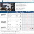
Weight of the Trailer<br />
Vehicle Maximum Trailer Weight GCWR*<br />
Regular Cab Model<br />
12,000 lbs (5 443 kg)<br />
22,000 lbs (9 980 kg)<br />
Crew Cab Model<br />
12,000 lbs (5 443 kg)<br />
22,000 lbs (9 980 kg)<br />
*The Gross Combination Weight Rating (GCWR) is the total allowable weight of the completely loaded<br />
vehicle and trailer including any passengers, cargo, equipment and conversion. The GCWR for the vehicle<br />
should not be exceeded.<br />
Towing capacity is limited by the military hitch, not vehicle performance.<br />
Refer to “Towing a Trailer” in the Vehicle Owner’s <strong>Manual</strong> for additional information.<br />
4-9
Pintle Hitch<br />
A pintle hitch is located at the rear of the vehicle, and<br />
is removable from the receiver.<br />
Notice: Before operating, inspect for proper operation,<br />
worn, damaged or missing parts and secure mountings.<br />
Correct as required before use.<br />
Operating the Pintle Hitch:<br />
To Open:<br />
1. Open the latch by removing latch pin (F).<br />
2. Pull up on the lock latch (C) while lifting the latch (D).<br />
To Close:<br />
1. Push the latch (D) until the lock latch (C) locks in<br />
place.<br />
2. Install the latch pin (F).<br />
Installing the Pintle Hitch:<br />
1. Remove any debris from the inside of the receiver.<br />
2. Push the pintle hitch (E) into the receiver.<br />
3. Install the retaining pin (B) into the receiver and the<br />
pintle hitch (E).<br />
4. Install the spring clip (A) into the retaining pin (B).<br />
15367<br />
4-10
Trailer Wiring Connector<br />
Trailer Connector Adapter<br />
10250<br />
On the military bumper the NATO standard 12-pin trailer<br />
lamp and brake connector is located on the rear bumper<br />
between the right clevis/tie-down and the pintle hitch.<br />
On the factory bumper the NATO standard 12-pin trailer<br />
lamp and brake connector is located on the rear trailer<br />
hitch to the left of the pintle hitch.<br />
When connecting a trailer wiring harness to the connector,<br />
make sure the dog ears of the connector are properly<br />
aligned when inserting it into the connector.<br />
7112<br />
When connecting to a commercial trailer with an 8-pin<br />
connector, the adapter must be used. This adapter allows<br />
you to connect an 8-pin trailer wiring harness into the<br />
vehicle’s 12-pin connector.<br />
4-11
NOTES<br />
4-12
Section 5 Service and Appearance Care<br />
Underhood Component Locator.......................................5-2<br />
Engine Compartment Overview...............................5-2<br />
Jump Starting.......................................................5-3<br />
Vent Filters.................................................................5-10<br />
Rear Axle Vent-Tube Filter....................................5-10<br />
Transfer Case Vent-Tube Filter..............................5-10<br />
Front Axle Vent-Tube Filter...................................5-10<br />
Replacement Bulbs....................................................5-11<br />
Appearance Care.......................................................5-12<br />
Cleaning the Outside of the Vehicle....................5-12<br />
Vehicle Information...................................................5-13<br />
Shipping Data Plate.............................................5-13<br />
Government Vehicle Data Plate............................5-13<br />
Electrical System.......................................................5-14<br />
Fuses and Circuit Breakers..................................5-14<br />
Tires...........................................................................5-11<br />
Changing a Flat Tire..................................................5-11<br />
Inflation-Tire Pressure............................................5-12<br />
5-1
Underhood Component Locator<br />
13905<br />
The following items are military options that may be found on the vehicle:<br />
A. 24-Volt Generator<br />
B. 24-Volt Generator Fuses<br />
C. Circuit Breakers<br />
D. 24-Volt Relay<br />
E. 24-Volt Battery<br />
5-2
Jump Starting<br />
If the battery (or batteries) on the vehicle have run down<br />
and the vehicle will not start, you may want to use another<br />
vehicle to provide power to start the vehicle.<br />
NATO slave cables are the only recommended method for<br />
24-volt jump starting of the vehicle. You should only use<br />
NATO slave cables to jump start similar vehicles.<br />
Heavy duty jumper cables can be used to jump start the<br />
12-volt system. See Jump Starting from a 12-volt System.<br />
Jump Starting from a 12-Volt System<br />
CAUTION:<br />
Batteries can hurt you. They can be dangerous<br />
because:<br />
• They contain acid that can burn you.<br />
• They contain gas that can explode or ignite.<br />
• They contain enough electricity to burn you.<br />
If you do not follow these steps exactly, some or all<br />
of these things can hurt you.<br />
Notice: Ignoring these steps could result in costly<br />
damage to the vehicle that would not be covered by the<br />
vehicle warranty. Trying to start the vehicle by pushing<br />
or pulling it will not work, and it could damage the vehicle.<br />
5-3
CAUTION:<br />
Using a open flame near a battery can cause battery<br />
gas to explode. People have been hurt doing this,<br />
and some have been blinded. Use a flashlight if you<br />
need more light.<br />
CAUTION:<br />
Fans or other moving engine parts can injure you<br />
badly. Keep your hands away from moving part<br />
once the engine is running.<br />
Be sure the batteries have enough water. You don’t<br />
need to add water to the Delco Freedom battery (or<br />
batteries) installed in every new <strong>GM</strong> vehicle. But if a<br />
battery has filler caps, be sure the right amount of<br />
fluid is there. If it is low, add water to take care of<br />
that first. If you do not explosive gas could be present.<br />
Battery fluid contains acid that can burn you. Do not<br />
get it on you. If you accidentally get it in the eyes or<br />
on the skin, flush the place with water and get<br />
medical help immediately.<br />
13896<br />
5. Connect the positive (+) cable to the positive (+)<br />
terminal of the 12-volt battery (12-volt side) of the<br />
vehicle with the dead battery.<br />
5-5
7. Connect the negative<br />
(-) cable to the negative<br />
(-) terminal of the<br />
12-volt system of the<br />
vehicle with the good<br />
battery.<br />
13898<br />
13897<br />
6. Connect the positive (+) cable to the positive (+)<br />
terminal 12-volt system of the vehicle with the<br />
good battery.<br />
Do not let the other end touch anything until the next step.<br />
The other end of the negative (-) cable does not go to the<br />
dead battery. It goes to a heavy unpainted metal part of the<br />
engine in the vehicle with the dead battery.<br />
8. Attach the cable at least 18 in (45 cm) away from<br />
the dead battery, but not near engine parts that<br />
move. The electrical connection is just as good<br />
there, but the chance of sparks getting back to<br />
the battery is much less.<br />
5-6
9. Start the vehicle with the good battery. Allow the<br />
vehicle’s battery to charge for 10 minutes before<br />
attempting to start the vehicle.<br />
Note: It may take up to 30 minutes to charge the battery<br />
enough to start the vehicle, depending on the battery’s<br />
state of charge.<br />
10. Start the vehicle with the dead battery.<br />
13899<br />
11. Remove the cables in reverse order to prevent<br />
electrical shorting. Take care that they do not<br />
touch each other or any other metal.<br />
A. 12-Volt Positive (Dead Battery)<br />
B. 12-Volt Positive (Good Battery)<br />
C. 12-Volt Negative (Good Battery)<br />
D. Engine Ground (Dead Battery)<br />
10586<br />
If this procedure does not work, you will need to disconnect<br />
the 24-volt side battery and charge it alone for 10 minutes.<br />
Replace the battery and repeat the jump starting procedures<br />
as outlined.<br />
Note: This procedure should only be performed by<br />
authorized personnel.<br />
5-7
Slave Starting<br />
CAUTION:<br />
Batteries can hurt you. They can be dangerous<br />
because:<br />
• They contain acid that can burn you.<br />
• They contain gas that can explode or ignite.<br />
• They contain enough electricity to burn you.<br />
If you do not follow these steps exactly, some or all<br />
of these things can hurt you.<br />
You should only use the NATO slave receptacle and<br />
slave cable when performing this operation.<br />
1. Get the vehicles close enough so that the slave<br />
cable can reach, but be sure the vehicles are not<br />
touching each other. If they are, it could cause a<br />
ground connection causing the vehicle not to start,<br />
and the bad grounding could damage the<br />
electrical systems.<br />
To avoid the possibility of the vehicles rolling, set the parking<br />
brake firmly on both vehicles involved in the jump start<br />
procedure. Put the automatic transmission in PARK (P).<br />
Be sure the transfer case is in a drive gear and is NOT in<br />
NEUTRAL (N).<br />
Notice: Ignoring these steps could result in costly<br />
damage to the vehicle that wouldn’t be covered by the<br />
vehicle warranty. Trying to start the vehicle by pushing<br />
or pulling it will not work, and it could damage the vehicle.<br />
5-8
2. Turn off the ignition on both vehicles. Unplug<br />
unnecessary accessories plugged into the<br />
cigarette lighter or accessory power outlets. Turn<br />
off all lamps that aren’t needed as well as radios.<br />
This will avoid sparks and help save both<br />
batteries. In addition, it could save the radio!<br />
Notice: If you leave the communications/navigation<br />
equipment on, they could be badly damaged. The<br />
repairs will not be covered by the warranty.<br />
CAUTION:<br />
Using a open flame near a battery can cause battery<br />
gas to explode. People have been hurt doing this,<br />
and some have been blinded. Use a flashlight if you<br />
need more light.<br />
Be sure the batteries have enough water. You don’t<br />
need to add water to the Delco Freedom ® battery<br />
(or batteries) installed in every new <strong>GM</strong> vehicle. But<br />
if a battery has filler caps, be sure the right amount<br />
of fluid is there. If it is low, add water to take care of<br />
that first. If you do not, explosive gas could be<br />
present.<br />
Battery fluid contains acid that can burn you. Do not<br />
get it on you. If you accidentally get it in the eyes or<br />
on the skin, flush the place with water and get<br />
medical help immediately.<br />
13895<br />
3. Locate the slave receptacles on both vehicles and<br />
unscrew the cover.<br />
CAUTION:<br />
Fans or other moving engine parts can injure you<br />
badly. Keep your hands away from moving parts<br />
once the engine is running.<br />
5-9
5-10<br />
14621<br />
4. Connect the slave<br />
cable to the vehicle<br />
with the dead battery.<br />
5. Connect the slave<br />
cable to the vehicle<br />
with the good battery.<br />
6. Start the vehicle with the good battery.<br />
7. Allow the vehicle with the dead battery to charge<br />
for 10 minutes.<br />
Note: It may take up to 30 minutes to charge the battery<br />
enough to start, depending on its state of charge.<br />
8. Start the vehicle with the dead battery.<br />
9. Remove the slave cable in the reverse order that<br />
it was installed. Take care not to let the cable<br />
ends touch each other or any other metal.<br />
Vent Filters<br />
Rear Axle Vent-Tube Filter<br />
The rear axle vent-tube filter is located on the vent hose that<br />
is attached to the top of the axle housing.<br />
Refer to the Maintenance Schedule to determine how often<br />
to inspect the filter and when to change it. See Front/<br />
Rear Axle Inspection.<br />
Transfer Case Vent-Tube Filter<br />
The transfer case vent-tube filter is located on the vent<br />
hose on the driver’s side of the transfer case housing.<br />
Refer to the Maintenance Schedule to determine how often<br />
to inspect the filter and when to change it. See Transfer<br />
Case Inspection.<br />
Front Axle Vent-Tube Filter<br />
The front axle vent-tube filter is located on the vent hose<br />
in the engine compartment near the left inner wheel well.<br />
Refer to the Maintenance Schedule to determine how often<br />
to inspect the filter and when to change it. See Front/<br />
Rear Axle Inspection.
Replacement Bulbs<br />
Lamp<br />
Blackout Headlamp<br />
Topper Dome Lamp<br />
24-Volt Gage Lamp<br />
License Plate Lamp<br />
Bulb Number<br />
1073<br />
194<br />
194<br />
194<br />
Tires<br />
Changing a Flat Tire<br />
Note: The bulbs in the blackout tail/stop lamp and front<br />
marker lamps are light emitting diodes (LED) instead of<br />
incandescent bulbs. They are not replaceable and are<br />
serviced as an assembly. For bulb replacement refer to the<br />
<strong>2003</strong> <strong>LSSV</strong> Military Trucks Service <strong>Manual</strong> <strong>Supplement</strong>.<br />
13901<br />
The military heavy duty bumper of the vehicle has an<br />
opening (A) to gain access to the spare tire hoist. For more<br />
information refer to “Changing a Flat Tire” in the Index of<br />
the <strong>2003</strong> Vehicle Owner’s <strong>Manual</strong>.<br />
5-11
Inflation-Tire Pressure<br />
Tire pressure should be within the manufacturer’s<br />
recommended range as indicated on the certification/tire<br />
label which is on the driver’s door edge. When hauling<br />
heavy loads the pressure should be at the maximum<br />
allowable pressure.<br />
Refer to “Inflation-Tire Pressure” in the Index of the <strong>2003</strong><br />
Vehicle Owner’s <strong>Manual</strong> for additional information on tire<br />
inflation pressure.<br />
Appearance Care<br />
Cleaning the Outside of the Vehicle<br />
Wash the vehicle using only mild soap and water. Do not<br />
use cleaning agents that are petroleum based, or that contain<br />
acid or abrasives. All cleaning agents should be flushed<br />
promptly and not allowed to dry on the surface. Do not<br />
towel dry or wax the paint surface.<br />
Cleaning the Soft Top (Cargo Cover)<br />
If the cargo cover has deteriorated, replace it. Refer to<br />
cargo cover replacement in the <strong>2003</strong> <strong>LSSV</strong> Military Trucks<br />
Service <strong>Manual</strong> <strong>Supplement</strong>.<br />
The cargo cover is a waterproof, welded, plastic coated<br />
polyester. Wash the cover using only mild soap and<br />
water. Do not use cleaning agents that are petroleum<br />
based, or that contain acid or abrasives. All cleaning<br />
agents should be flushed promptly and not allowed to<br />
dry on the surface. Do not towel dry or wax the surface.<br />
The windows should be washed with a water soaked<br />
cloth. Do not rub dry.<br />
5-12
Vehicle Information<br />
Shipping Data Plate<br />
Government Vehicle Data Plate<br />
14550<br />
The data plate is used to inform the operator of the<br />
vehicle as to the make, model, Gross Vehicle Weight<br />
(GVW), and vehicle dimensions. It is located on the left<br />
corner of the left front inner door panel.<br />
15140 9565<br />
The data plate is used to inform the operator of the<br />
vehicle as to the upfitting information and other<br />
specifications. It is located on the left front corner of the<br />
inner door panel.<br />
5-13
Electrical System<br />
Fuses and Circuit Breakers<br />
Circuit breakers protect the power accessories. When the<br />
current load is too heavy, the circuit breaker opens,<br />
protecting the circuit until the problem is fixed.<br />
24-Volt Power Source (Battery Equalizer)<br />
24-Volt Circuit Breakers<br />
These circuit breakers are on the left rear fender support<br />
bracket of the engine compartment.<br />
13948<br />
13902<br />
A. 24-Volt Stud on Equalizer<br />
B. 24-Volt Stud on Equalizer Cover<br />
C. Fuel Fired Heater<br />
D. Auxiliary Items<br />
The battery equalizer is located on the left rear wall of the<br />
cab. The primary function of the battery equalizer is to<br />
maintain battery balance or equalization charge in a<br />
predominately 24-volt system which requires regulated<br />
12-volt power. The battery equalizer can deliver up to<br />
100 amps of continuous 12-volt current for practically any<br />
12-volt or 24-volt load such as two way radios, navigations<br />
or the 24-volt batteries.<br />
5-14
NOTES<br />
5-15
NOTES<br />
5-16
Section 6 Maintenance Schedule<br />
Maintenance Schedule..............................................6-2<br />
Front/Rear Axle Inspection....................................6-2<br />
Transfer Case Inspection......................................6-2<br />
Fuel Fired Coolant Heater Inspection.....................6-3<br />
Winch Inspection..................................................6-3<br />
6-1
Maintenance Schedule<br />
Front/Rear Axle Inspection<br />
Inspect the front/rear axle fluid level and add as needed.<br />
Inspect the constant velocity joints and axle seals for<br />
leakage.<br />
The front and rear axles are equipped with an in-line filter<br />
on the vent tubes. Inspect the filters for blockages and<br />
replace as needed. See “Front Axle Vent-Tube Filter” and<br />
“Rear Axle Vent-Tube Filter” in the Index for further<br />
information on the location of the front and rear axle<br />
filters. Refer to “Maintenance Schedule” in the Index of<br />
the <strong>2003</strong> Vehicle Owner’s <strong>Manual</strong> for additional<br />
maintenance information on the vehicle.<br />
Transfer Case Inspection<br />
Inspect the transfer case fluid level and add lubricant if<br />
necessary. On manual shift transfer case, oil the control<br />
lever pivot point and all exposed control linkage.<br />
The transfer case is equipped with an in-line filter on the<br />
vent tube. Inspect the filter for blockages and replace as<br />
needed. Inspect vent hose at the transfer case for kinks<br />
and proper installation. See “Transfer Case Vent-Tube<br />
Filter” in the Index for further information on the location<br />
of the filter. Refer to “Maintenance Schedule” in the Index<br />
of the <strong>2003</strong> Vehicle Owner’s <strong>Manual</strong> for additional<br />
maintenance information on the vehicle.<br />
6-2
Fuel Fired Coolant Heater Inspection<br />
The heater requires no periodic maintenance other than a<br />
visual inspection by a qualified technician preferably prior<br />
to cold weather use. The technician can ensure that the<br />
heater and all components are free from damage and in<br />
proper working condition.<br />
During the warmer months of the year when heating is not<br />
required, the heater should be switched ON and allowed to<br />
run for 5 to 10 minutes once a month at a minimum.<br />
This will keep a clean, fresh supply of fuel in the heater<br />
fuel system and keep all moving parts in top operating<br />
condition.<br />
Winch Inspection<br />
Inspect the wire rope before and after each winching<br />
operation. If the wire rope has become kinked or frayed, the<br />
wire rope needs to be replaced. Be sure to also inspect the<br />
winch hook and hook pin for signs of wear or damage,<br />
and replace if necessary.<br />
Inspect the remote control for damage, if equipped. Refer<br />
to the WARN industries operator’s manual in the vehicle’s<br />
glove compartment for additional inspection and<br />
maintenance information.<br />
For troubleshooting information refer to the <strong>2003</strong> <strong>LSSV</strong><br />
Military Trucks Service <strong>Manual</strong> <strong>Supplement</strong>.<br />
6-3
6-4<br />
NOTES
Section 7 Customer Assistance Information<br />
Customer Assistance Information..............................7-2<br />
Contact Information...............................................7-2<br />
7-1
Customer Assistance Information<br />
For customer assistance phone numbers, refer to Contact<br />
Information.<br />
To assist in our review of your concerns, provide the following<br />
information:<br />
Contact Information<br />
Telephone Users<br />
Department<br />
<strong>GM</strong> Customer Assistance Center<br />
(general information, dealer<br />
location, other concerns):<br />
Phone Number<br />
1-800-222-1020<br />
• The Vehicle Identification Number. (This will<br />
be on the VIN plate in the cab of the vehicle)<br />
• Current mileage on the vehicle<br />
Roadside Assistance Center<br />
(towing and all Roadside<br />
Assistance program services):<br />
1-800-243-8872<br />
• Nature of the problem<br />
Online Users<br />
You can find specific information on:<br />
• Service Parts<br />
• After Sales Assistance<br />
• <strong>GM</strong> Military History<br />
• News/Events<br />
Refer to the web for updated information:<br />
www.gm-defense.com<br />
7-2
A<br />
Appearance Care.................................................................5-12<br />
Cleaning the Outside of the Vehicle......................5-12<br />
Cleaning the Soft Top (Cargo Cover)....................5-12<br />
B<br />
Blackout Drive Light Control..............................................3-3<br />
C<br />
Cargo Cover-Soft Top..........................................................2-5<br />
Cargo Tie Downs.................................................................2-7<br />
Changing a Flat Tire..........................................................5-11<br />
Cleaning the Outside of the Vehicle...............................5-12<br />
Cleaning the Soft Top (Cargo Cover).............................5-12<br />
Customer Assistance Information....................................7-2<br />
Contact Information.....................................................7-2<br />
D<br />
Driving the Vehicle.......................................................................iii<br />
E<br />
Electrical System..................................................................5-14<br />
Fuses and Circuit Breakers....................................5-14<br />
24-Volt Circuit Breakers.............................................5-14<br />
24-Volt Power Source................................................5-14<br />
Exterior Lamps......................................................................3-2<br />
Service and Blackout Lighting..................................3-2<br />
Service Lights/Blackout Control...............................3-2<br />
Blackout Drive Light Controls...................................3-3<br />
Operating Service and Blackout Lighting...............3-4<br />
F<br />
Folding the Seats Down.....................................................1-2<br />
Folding the Seats Up..........................................................1-3<br />
Front Axle Vent-Tube Filter..............................................5-10<br />
Front Clevis/Towing Provisions.......................................4-6<br />
Front/Rear Axle Inspection................................................6-2<br />
Fuel Fired Coolant Heater................................................2-4<br />
Fuel Fired Coolant Heater Operation.....................2-4<br />
Fuses and Circuit Breakers.............................................5-14<br />
Fuel Fired Coolant Heater Inspection.............................6-3<br />
G<br />
Government Vehicle Data Plate......................................5-13<br />
8-1
H<br />
How to Use This <strong>Manual</strong>...........................................................ii<br />
I<br />
If You’re Stuck: in Sand, Mud, Ice or Snow....................4-5<br />
Using the Clevis/Towing Provisions........................4-5<br />
Front Clevis/Towing Provisions.................................4-6<br />
Rear Clevis/Towing Provisions.................................4-6<br />
Maximum Allowable Loads On Each<br />
Clevis/Towing Shackle.............................................4-7<br />
Inflation-Tire Pressure.........................................................5-12<br />
Installing the Pintle Hitch..................................................4-10<br />
Interior Lamps.......................................................................3-6<br />
Topper Dome Lamp...................................................3-6<br />
J<br />
Jump Starting........................................................................5-3<br />
Jump Starting from a 12-Volt System..............................5-3<br />
L<br />
Loading the Vehicle......................................................4-2,4-8<br />
M<br />
Maintenance Schedule........................................................6-2<br />
Front/Rear Axle Inspection........................................6-2<br />
Transfer Case Inspection.........................................6-2<br />
Fuel Fired Coolant Heater Inspection....................6-3<br />
Winch Inspection.........................................................6-3<br />
Maximum Allowable Loads on Each<br />
Clevis/Towing Shackle..............................................4-7<br />
Mounting the Weapon.........................................................2-8<br />
Multi-Mount Winch................................................................4-3<br />
O<br />
Operating the Pintle Hitch................................................4-10<br />
Operating Service and Blackout Lighting........................3-4<br />
P<br />
Permanent Mount Winch....................................................4-4<br />
Pintle Hitch.............................................................................4-10<br />
Operating the Pintle Hitch........................................4-10<br />
Installing the Pintle Hitch.........................................4-10<br />
8-2
R<br />
Rear Axle Vent-Tube Filter.............................................5-10<br />
Rear Clevis/Towing Provisions.........................................4-6<br />
Rear Topper Window...........................................................2-2<br />
Replacement Bulbs.............................................................5-11<br />
Restraints................................................................................1-3<br />
Rear Safety Strap........................................................1-3<br />
S<br />
Safety Warnings and Symbols...........................................iii<br />
Service and Blackout Lighting...........................................3-2<br />
Side Topper Window...........................................................2-2<br />
Shipping Data Plate.....................................................5-13<br />
Sliding Rear Window...........................................................2-3<br />
Starting and Operating the Vehicle..................................2-3<br />
Starting the Engine.....................................................2-3<br />
Storage Areas........................................................................2-5<br />
Cargo Cover-Soft Top.................................................2-5<br />
Rolling Up the Side Panels......................................2-5<br />
Storing the Cargo Cover.............................................2-5<br />
Slave Starting................................................................5-8<br />
T<br />
Tires.........................................................................................5-11<br />
Changing a Flat Tire.................................................5-11<br />
Inflation-Tire Pressure................................................5-12<br />
Topper Dome Lamp............................................................3-6<br />
Towing......................................................................................4-8<br />
Towing the Vehicle......................................................4-8<br />
Towing a Trailer...........................................................4-8<br />
Loading the Vehicle....................................................4-8<br />
Weight of the Trailer....................................................4-9<br />
Trailer Connector Adaptor..................................................4-11<br />
Trailer Wiring Connector....................................................4-11<br />
Transfer Case Inspection..................................................6-2<br />
Transfer Case Vent-Tube Filter.......................................5-10<br />
Troop Seats...........................................................................1-2<br />
Troop Seat Operation.................................................1-2<br />
Folding the Seats Down............................................1-2<br />
Folding the Seats Up.................................................1-3<br />
24-Volt Circuit Breakers.....................................................5-14<br />
24-Volt Power Source.........................................................5-14<br />
24-Volt Gage..........................................................................3-8<br />
U<br />
Underhood Component Locator.......................................5-2<br />
Jump Starting................................................................5-3<br />
Jump Starting from a 12-Volt System.....................5-3<br />
Slave Starting................................................................5-8<br />
Using the Clevis/Towing Provisions................................4-5<br />
Using JP8 as a Fuel...........................................................4-2<br />
8-3
V<br />
Vehicle Damage Warnings.......................................................iii<br />
Vehicle Information...............................................................5-13<br />
Shipping Data Plate...................................................5-13<br />
Government Vehicle Data Plate..............................5-13<br />
Vent Filters.............................................................................5-10<br />
Rear Axle Vent-Tube Filter........................................5-10<br />
Transfer Case Vent-Tube Filter...............................5-10<br />
Front Axle Vent-Tube Filter......................................5-10<br />
Windows..................................................................................2-2<br />
Rear Topper Window..................................................2-2<br />
Side Topper Window..................................................2-2<br />
Sliding Rear Window..................................................2-3<br />
Y<br />
Your Driving, the Road and<br />
the Vehicle.........................................................................4-2<br />
Loading the Vehicle....................................................4-2<br />
8-4<br />
W<br />
Warning Lights, Gages and Indicators...........................3-8<br />
24-Volt Gage.................................................................3-8<br />
Weapons Mount....................................................................2-7<br />
Weapons Mount (Floor Mount).................................2-7<br />
Weapons Mount (Cab Mount)...................................2-8<br />
Weight of the Trailer.............................................................4-9<br />
Winch Accessory Kit............................................................4-4<br />
Winch Inspection..................................................................6-3<br />
Winch.......................................................................................4-3<br />
Multi-Mount.....................................................................4-3<br />
Winch Storage..............................................................4-3<br />
Control of the Winch...................................................4-4<br />
How the Winch Reacts to Load...............................4-4<br />
Permanent Mount........................................................4-4