RF Power Field Effect Transistor MRF5015 - igor
RF Power Field Effect Transistor MRF5015 - igor
RF Power Field Effect Transistor MRF5015 - igor

Create successful ePaper yourself
Turn your PDF publications into a flip-book with our unique Google optimized e-Paper software.
SEMICONDUCTOR TECHNICAL DATA<br />
Order this document<br />
by M<strong>RF</strong>5015/D<br />
The <strong>RF</strong> MOSFET Line<br />
<br />
N–Channel Enhancement–Mode<br />
Designed for broadband commercial and industrial applications at frequencies<br />
to 520 MHz. The high gain and broadband performance of this device<br />
makes it ideal for large–signal, common source amplifier applications in 12.5<br />
volt mobile, and base station FM equipment.<br />
• Guaranteed Performance at 512 MHz, 12.5 Volts<br />
Output <strong>Power</strong> — 15 Watts<br />
<strong>Power</strong> Gain — 10 dB Min<br />
Efficiency — 50% Min<br />
• Characterized with Series Equivalent Large–Signal Impedance Parameters<br />
• S–Parameter Characterization at High Bias Levels<br />
• Excellent Thermal Stability<br />
• All Gold Metal for Ultra Reliability<br />
• Capable of Handling 20:1 VSWR, @ 15.5 Vdc, 512 MHz, 2 dB Overdrive<br />
• Circuit board photomaster available upon request by contacting<br />
<strong>RF</strong> Tactical Marketing in Phoenix, AZ.<br />
<br />
15 W, 512 MHz, 12.5 VOLTS<br />
N–CHANNEL BROADBAND<br />
<strong>RF</strong> POWER FET<br />
MAXIMUM RATINGS<br />
Rating Symbol Value Unit<br />
Drain–Source Voltage VDSS 36 Vdc<br />
Drain–Gate Voltage (RGS = 1 MΩ) VDGR 36 Vdc<br />
Gate–Source Voltage VGS ± 20 Vdc<br />
Drain Current — Continuous ID 6 Adc<br />
Total Device Dissipation @ TC = 25°C<br />
Derate above 25°C<br />
PD 50<br />
0.29<br />
Storage Temperature Range Tstg – 65 to +150 °C<br />
Operating Junction Temperature TJ 200 °C<br />
THERMAL CHARACTERISTICS<br />
CASE 319–07, STYLE 3<br />
Watts<br />
W/°C<br />
Characteristic Symbol Max Unit<br />
Thermal Resistance, Junction to Case RθJC 3.5 °C/W<br />
ELECTRICAL CHARACTERISTICS (TC = 25°C unless otherwise noted.)<br />
Characteristic Symbol Min Typ Max Unit<br />
OFF CHARACTERISTICS<br />
Drain–Source Breakdown Voltage (VGS = 0, ID = 5 mAdc) V(BR)DSS 36 — — Vdc<br />
Zero Gate Voltage Drain Current (VDS = 15 Vdc, VGS = 0) IDSS — — 5 mAdc<br />
Gate–Source Leakage Current (VGS = 20 Vdc, VDS = 0) IGSS — — 2 µAdc<br />
NOTE – CAUTION – MOS devices are susceptible to damage from electrostatic charge. Reasonable precautions in handling and<br />
packaging MOS devices should be observed.<br />
(continued)<br />
REV 6<br />
© MOTOROLA Motorola, Inc. 1994 <strong>RF</strong> DEVICE DATA<br />
M<strong>RF</strong>5015<br />
1
ELECTRICAL CHARACTERISTICS — continued (TC = 25°C unless otherwise noted.)<br />
Characteristic Symbol Min Typ Max Unit<br />
ON CHARACTERISTICS<br />
Gate Threshold Voltage<br />
VGS(th) 1.25 2.3 3.5 Vdc<br />
(VDS = 10 Vdc, ID = 10 mAdc)<br />
Drain–Source On–Voltage<br />
(VGS = 10 Vdc, ID = 1 Adc)<br />
Forward Transconductance<br />
(VDS = 10 Vdc, ID = 1 Adc )<br />
DYNAMIC CHARACTERISTICS<br />
Input Capacitance<br />
(VDS = 12.5 Vdc, VGS = 0, f = 1 MHz)<br />
Output Capacitance<br />
(VDS = 12.5 Vdc, VGS = 0, f = 1 MHz)<br />
Reverse Transfer Capacitance<br />
(VDS = 12.5 Vdc, VGS = 0, f = 1 MHz)<br />
VDS(on) — — 0.375 Vdc<br />
gfs 1.2 — — S<br />
Ciss — 33 — pF<br />
Coss — 74 — pF<br />
Crss 7 8.8 10.8 pF<br />
FUNCTIONAL TESTS (In Motorola Test Fixture)<br />
Common–Source Amplifier <strong>Power</strong> Gain<br />
(VDD = 12.5 Vdc, Pout = 15 W,<br />
IDQ = 100 mA)<br />
f = 512 MHz<br />
f = 175 MHz<br />
Gps<br />
10<br />
—<br />
11.5<br />
15<br />
—<br />
—<br />
dB<br />
Drain Efficiency<br />
(VDD = 12.5 Vdc, Pout = 15 W,<br />
IDQ = 100 mA)<br />
f = 512 MHz<br />
f = 175 MHz<br />
η<br />
50<br />
—<br />
55<br />
55<br />
—<br />
—<br />
%<br />
Load Mismatch<br />
(VDD = 15.5 Vdc, 2 dB Overdrive, f = 512 MHz,<br />
Load VSWR = 20:1, All Phase Angles at Frequency of Test)<br />
ψ<br />
No Degradation in Output <strong>Power</strong><br />
VGG<br />
R1<br />
B1<br />
+ +<br />
R2 C1 C2<br />
B1 C12 C13<br />
C3<br />
Socket<br />
VDD<br />
<strong>RF</strong><br />
Input<br />
N1<br />
Z4<br />
C11<br />
L1<br />
R3<br />
DUT<br />
L2<br />
Z1 C4 Z2 Z3<br />
Z6<br />
Z7<br />
Z8<br />
Z9 Z10 C10 Z11 N2<br />
<strong>RF</strong><br />
Output<br />
C5<br />
C7<br />
C8 C9<br />
Z5 C6<br />
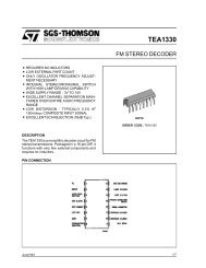
B1, B2 Ferrite Bead, Fair Rite Products<br />
C1, C13 10 µF, 50 V, Electrolytic<br />
C2, C12 0.1 µF, Chip Capacitor<br />
C3, C4, C10, C11 120 pF, Chip Capacitor<br />
C5, C9 0 to 20 pF, Trimmer Capacitor<br />
C6<br />
36 pF, Chip Capacitor<br />
C7<br />
43 pF, Chip Capacitor<br />
C8<br />
30 pF, Chip Capacitor<br />
L1, L2 7 Turns, 24 AWG 0.116″ ID<br />
N1, N2 Type N Flange Mount<br />
R1<br />
1 kΩ, 1/4 W, Carbon<br />
R2<br />
470 kΩ, 1/4 W, Carbon<br />
R3<br />
160 Ω, 0.1 W Chip<br />
Z1, Z11 Transmission Line*<br />
Z2<br />
Transmission Line*<br />
Z3<br />
Transmission Line*<br />
Z4<br />
Transmission Line*<br />
Z5<br />
Transmission Line*<br />
Z6<br />
Transmission Line*<br />
Z7, Z8 Transmission Line+<br />
Z9<br />
Transmission Line*<br />
Z10<br />
Transmission Line*<br />
Board Glass Teflon® 0.060″<br />
+ Part of Capacitor Mount Socket<br />
*See Photomaster<br />
Figure 1. 512 MHz Narrowband Test Circuit Electrical Schematic<br />
M<strong>RF</strong>5015<br />
2<br />
MOTOROLA <strong>RF</strong> DEVICE DATA
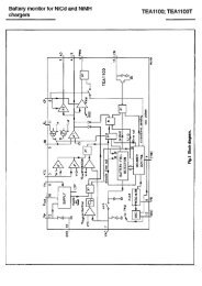
TYPICAL CHARACTERISTICS<br />
P out , OUTPUT POWER (WATTS)<br />
25<br />
20<br />
15<br />
10<br />
5<br />
f = 400 MHz<br />
470 MHz<br />
520 MHz<br />
VDD = 12.5 V<br />
IDQ = 100 mA<br />
P out , OUTPUT POWER (WATTS)<br />
25<br />
20<br />
15<br />
10<br />
5<br />
IDQ = 100 mA<br />
f = 520 MHz<br />
Pin = 1.5 W<br />
1 W<br />
0.5 W<br />
0<br />
0<br />
0<br />
0.5 1<br />
1.5 2 2.5<br />
6 8<br />
10<br />
12<br />
14<br />
16<br />
Pin, INPUT POWER (WATTS)<br />
VDD, SUPPLY VOLTAGE (VOLTS)<br />
Figure 2. Output <strong>Power</strong> versus Input <strong>Power</strong><br />
Figure 3. Output <strong>Power</strong> versus Supply Voltage<br />
P out , OUTPUT POWER (WATTS)<br />
25<br />
20<br />
15<br />
10<br />
5<br />
0<br />
VDD = 12.5 V<br />
Pin = 1.5 W<br />
f = 520 MHz<br />
Typical Device Shown<br />
I D , DRAIN CURRENT (AMPS)<br />
2<br />
1.8<br />
1.6<br />
1.4<br />
1.2<br />
1<br />
0.8<br />
0.6<br />
0.4<br />
0.2<br />
VDS = 10 V<br />
Typical Device Shown<br />
0<br />
1 2 3 4 5 6<br />
0<br />
1 2<br />
3<br />
4<br />
VGS, GATE–SOURCE VOLTAGE (VOLTS)<br />
VGS, GATE–SOURCE VOLTAGE (VOLTS)<br />
Figure 4. Output <strong>Power</strong> versus Gate Voltage<br />
Figure 5. Drain Current versus Gate Voltage<br />
C, CAPACITANCE (pF)<br />
200<br />
150<br />
100<br />
50<br />
0<br />
0<br />
Coss<br />
VGS = 0<br />
f = 1 MHz<br />
V GS , GATE-SOURCE VOLTAGE (NORMALIZED)<br />
1.04<br />
1.03<br />
1.02<br />
1.01<br />
1.00<br />
0.99<br />
0.98<br />
0.97<br />
VDD = 12.5 V<br />
ID = 1.5 A<br />
ID = 1 A<br />
Ciss<br />
0.96<br />
ID = 0.5 A<br />
ID = 0.05 A<br />
Crss<br />
0.95<br />
ID = 0.25 A<br />
0.94<br />
5 10 15 20 25 30 – 25 0 25 50 75 100 125 150 175<br />
VDS, DRAIN–SOURCE VOLTAGE (VOLTS)<br />
TC, CASE TEMPERATURE (°C)<br />
Figure 6. Capacitance versus Voltage<br />
Figure 7. Gate–Source Voltage<br />
versus Case Temperature<br />
MOTOROLA <strong>RF</strong> DEVICE DATA<br />
M<strong>RF</strong>5015<br />
3
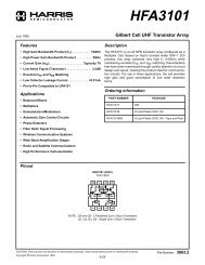
TYPICAL CHARACTERISTICS<br />
10<br />
, DRAIN CURRENT (AMPS)<br />
1<br />
TC = 25°C<br />
I D<br />
0.1<br />
1<br />
10<br />
VDS, DRAIN–SOURCE VOLTAGE (VOLTS)<br />
Figure 8. DC Safe Operating Area<br />
100<br />
VDD = 12.5 V, IDQ = 100 mA, Pout = 15 W<br />
f<br />
(MHz)<br />
400<br />
420<br />
440<br />
Zin<br />
(Ω)<br />
2.0 – j6.1<br />
1.8 – j5.3<br />
1.6 – j4.7<br />
ZOL*<br />
(Ω)<br />
1.3 – j0.4<br />
1.4 – j0.4<br />
1.5 – j0.4<br />
ZOL*<br />
520<br />
460<br />
460<br />
1.5 – j4.2<br />
1.5 – j0.3<br />
480 1.4 – j3.8 1.5 – j0.2<br />
f = 400 MHz<br />
500 1.3 – j3.6 1.4 – j0.1<br />
Zo = 10 Ω<br />
520 1.2 – j3.5 1.3 + j0.1<br />
520<br />
Zin<br />
460<br />
f = 400 MHz<br />
Zin = Conjugate of source impedance with<br />
parallel 160 Ω resistor and 36 pF capacitor<br />
in series with gate.<br />
ZOL* =<br />
Conjugate of the load impedance at given<br />
output power, voltage and frequency that<br />
produces maximum gain.<br />
Figure 9. Series Equivalent Input and Output Impedance<br />
M<strong>RF</strong>5015<br />
4<br />
MOTOROLA <strong>RF</strong> DEVICE DATA
Table 1. Common Source Scattering Parameters (VDS = 12.5 V)<br />
ID = 50 mA<br />
f S11 S21 S12 S22<br />
MHz |S11| ∠ φ |S21| ∠ φ |S12| ∠ φ |S22| ∠ φ<br />
50<br />
100<br />
200<br />
300<br />
400<br />
500<br />
700<br />
850<br />
1000<br />
0.63<br />
0.62<br />
0.70<br />
0.78<br />
0.84<br />
0.88<br />
0.93<br />
0.95<br />
0.96<br />
–123<br />
–142<br />
–152<br />
–157<br />
–162<br />
–165<br />
–171<br />
–175<br />
–178<br />
8<br />
4<br />
1.8<br />
1.1<br />
0.70<br />
0.49<br />
0.28<br />
0.20<br />
0.15<br />
100<br />
82<br />
61<br />
47<br />
36<br />
28<br />
17<br />
13<br />
10<br />
0.063<br />
0.063<br />
0.056<br />
0.046<br />
0.037<br />
0.029<br />
0.016<br />
0.010<br />
0.007<br />
11<br />
–6<br />
–23<br />
–35<br />
–42<br />
–46<br />
–45<br />
–31<br />
11<br />
0.79<br />
0.82<br />
0.86<br />
0.90<br />
0.93<br />
0.94<br />
0.97<br />
0.97<br />
0.98<br />
–149<br />
–162<br />
–169<br />
–171<br />
–174<br />
–175<br />
–179<br />
179<br />
178<br />
ID = 100 mA<br />
f S11 S21 S12 S22<br />
MHz |S11| ∠ φ |S21| ∠ φ |S12| ∠ φ |S22| ∠ φ<br />
50<br />
100<br />
200<br />
300<br />
400<br />
500<br />
700<br />
850<br />
1000<br />
0.67<br />
0.66<br />
0.71<br />
0.77<br />
0.82<br />
0.86<br />
0.91<br />
0.93<br />
0.95<br />
–136<br />
–153<br />
–160<br />
–163<br />
–165<br />
–168<br />
–173<br />
–176<br />
–179<br />
9.1<br />
4.6<br />
2.2<br />
1.3<br />
0.89<br />
0.64<br />
0.37<br />
0.27<br />
0.20<br />
99<br />
84<br />
66<br />
54<br />
44<br />
36<br />
25<br />
20<br />
16<br />
0.047<br />
0.048<br />
0.043<br />
0.037<br />
0.031<br />
0.025<br />
0.015<br />
0.010<br />
0.009<br />
10<br />
–3<br />
–17<br />
–26<br />
–32<br />
–35<br />
–30<br />
–11<br />
25<br />
0.82<br />
0.85<br />
0.87<br />
0.90<br />
0.92<br />
0.94<br />
0.96<br />
0.97<br />
0.98<br />
–158<br />
–168<br />
–172<br />
–174<br />
–175<br />
–177<br />
–179<br />
179<br />
177<br />
ID = 500 mA<br />
f S11 S21 S12 S22<br />
MHz |S11| ∠ φ |S21| ∠ φ |S12| ∠ φ |S22| ∠ φ<br />
50<br />
100<br />
200<br />
300<br />
400<br />
500<br />
700<br />
850<br />
1000<br />
0.81<br />
0.81<br />
0.82<br />
0.84<br />
0.86<br />
0.88<br />
0.91<br />
0.93<br />
0.94<br />
–150<br />
–164<br />
–170<br />
–173<br />
–174<br />
–175<br />
–178<br />
180<br />
178<br />
11.1<br />
5.6<br />
2.7<br />
1.7<br />
1.2<br />
0.92<br />
0.57<br />
0.43<br />
0.33<br />
98<br />
86<br />
73<br />
63<br />
55<br />
47<br />
35<br />
29<br />
23<br />
0.027<br />
0.027<br />
0.025<br />
0.023<br />
0.020<br />
0.018<br />
0.013<br />
0.013<br />
0.014<br />
11<br />
2<br />
–5<br />
–9<br />
–9<br />
–7<br />
7<br />
26<br />
44<br />
0.85<br />
0.87<br />
0.88<br />
0.89<br />
0.91<br />
0.92<br />
0.94<br />
0.95<br />
0.96<br />
–168<br />
–174<br />
–176<br />
–177<br />
–178<br />
–179<br />
180<br />
178<br />
177<br />
ID = 2.5 A<br />
f S11 S21 S12 S22<br />
MHz |S11| ∠ φ |S21| ∠ φ |S12| ∠ φ |S22| ∠ φ<br />
50<br />
100<br />
200<br />
300<br />
400<br />
500<br />
700<br />
850<br />
1000<br />
0.86<br />
0.85<br />
0.86<br />
0.87<br />
0.89<br />
0.91<br />
0.93<br />
0.94<br />
0.95<br />
–144<br />
–161<br />
–170<br />
–173<br />
–175<br />
–176<br />
–179<br />
179<br />
177<br />
10.1<br />
5.2<br />
2.5<br />
1.6<br />
1.1<br />
0.84<br />
0.52<br />
0.39<br />
0.30<br />
101<br />
88<br />
74<br />
64<br />
55<br />
48<br />
37<br />
30<br />
26<br />
0.022<br />
0.022<br />
0.021<br />
0.019<br />
0.017<br />
0.015<br />
0.013<br />
0.014<br />
0.016<br />
15<br />
5<br />
–1<br />
–4<br />
–2<br />
2<br />
22<br />
39<br />
52<br />
0.85<br />
0.87<br />
0.89<br />
0.90<br />
0.91<br />
0.93<br />
0.95<br />
0.96<br />
0.96<br />
–171<br />
–175<br />
–177<br />
–178<br />
–178<br />
–179<br />
179<br />
178<br />
176<br />
MOTOROLA <strong>RF</strong> DEVICE DATA<br />
M<strong>RF</strong>5015<br />
5
DESIGN CONSIDERATIONS<br />
The M<strong>RF</strong>5015 is a common–source, <strong>RF</strong> power, N–Channel<br />
enhancement mode, Metal–Oxide Semiconductor <strong>Field</strong>–<br />
<strong>Effect</strong> <strong>Transistor</strong> (MOSFET). Motorola <strong>RF</strong> MOSFETs feature<br />
a vertical structure with a planar design. Motorola Application<br />
Note AN211A, “FETs in Theory and Practice,” is suggested<br />
reading for those not familiar with the construction and characteristics<br />
of FETs.<br />
This device was designed primarily for 12.5 volt VHF and<br />
UHF power amplifier applications. The major advantages of<br />
<strong>RF</strong> power MOSFETs include high gain, simple bias systems,<br />
relative immunity from thermal runaway, and the ability to<br />
withstand severely mismatched loads without suffering damage.<br />
MOSFET CAPACITANCES<br />
The physical structure of a MOSFET results in capacitors<br />
between all three terminals. The metal oxide gate structure<br />
determines the capacitors from gate–to–drain (Cgd), and<br />
gate–to–source (Cgs). The PN junction formed during fabrication<br />
of the <strong>RF</strong> MOSFET results in a junction capacitance<br />
from drain–to–source (Cds). These capacitances are characterized<br />
as input (Ciss), output (Coss) and reverse transfer<br />
(Crss) capacitances on data sheets. The relationships between<br />
the inter–terminal capacitances and those given on<br />
data sheets are shown below. The Ciss can be specified in<br />
two ways:<br />
1. Drain shorted to source and positive voltage at the gate.<br />
2. Positive voltage of the drain in respect to source and<br />
2. zero volts at the gate.<br />
In the latter case, the numbers are lower. However, neither<br />
method represents the actual operating conditions in <strong>RF</strong> applications.<br />
Gate<br />
Cgd<br />
Cgs<br />
Drain<br />
Cds<br />
DRAIN CHARACTERISTICS<br />
Source<br />
Ciss = Cgd + Cgs<br />
Coss = Cgd + Cds<br />
Crss = Cgd<br />
One critical figure of merit for a FET is its static resistance<br />
in the full–on condition. This on–resistance, Rds(on), occurs<br />
in the linear region of the output characteristic and is specified<br />
at a specific gate–source voltage and drain current. The<br />
drain–source voltage under these conditions is termed<br />
Vds(on). For MOSFETs, Vds(on) has a positive temperature<br />
coefficient at high temperatures because it contributes to the<br />
power dissipation within the device.<br />
GATE CHARACTERISTICS<br />
The gate of the <strong>RF</strong> MOSFET is a polysilicon material, and<br />
is electrically isolated from the source by a layer of oxide.<br />
The input resistance is very high, on the order of 109 Ω, resulting<br />
in a leakage current of a few nanoamperes.<br />
Gate control is achieved by applying a positive voltage to<br />
the gate greater than the gate–to–source threshold voltage,<br />
VGS(th).<br />
Gate Voltage Rating – Never exceed the gate voltage rating.<br />
Exceeding the rated VGS can result in permanent damage<br />
to the oxide layer in the gate region.<br />
Gate Termination – The gates of these devices are essentially<br />
capacitors. Circuits that leave the gate open–circuited<br />
or floating must be avoided. These conditions can<br />
result in turn–on of the devices due to voltage build–up on<br />
the input capacitor due to leakage currents or pickup.<br />
Gate Protection – These devices do not have an internal<br />
monolithic zener diode from gate–to–source. If gate protection<br />
is required, an external zener diode is recommended<br />
with appropriate <strong>RF</strong> decoupling networks.<br />
Using a resistor to keep the gate–to–source impedance<br />
low also helps dampen transients and serves another important<br />
function. Voltage transients on the drain can be coupled<br />
to the gate through the parasitic gate–drain capacitance. If<br />
the gate–to–source impedance and the rate of voltage<br />
change on the drain are both high, then the signal coupled to<br />
the gate may be large enough to exceed the gate–threshold<br />
voltage and turn the device on.<br />
DC BIAS<br />
Since the M<strong>RF</strong>5015 is an enhancement mode FET, drain<br />
current flows only when the gate is at a higher potential than<br />
the source. See Figure 5 for a typical plot of drain current<br />
versus gate voltage. <strong>RF</strong> power FETs operate optimally with a<br />
quiescent drain current (IDQ), whose value is application dependent.<br />
The M<strong>RF</strong>5015 was characterized at IDQ = 100 mA,<br />
which is the suggested value of bias current for typical applications.<br />
For special applications such as linear amplification,<br />
IDQ may have to be selected to optimize the critical<br />
parameters.<br />
The gate is a dc open circuit and draws essentially no current.<br />
Therefore, the gate bias circuit may generally be just a<br />
simple resistive divider network. Some special applications<br />
may require a more elaborate bias system.<br />
GAIN CONTROL<br />
<strong>Power</strong> output of the M<strong>RF</strong>5015 may be controlled to some<br />
degree with a low power dc control signal applied to the gate,<br />
thus facilitating applications such as manual gain control,<br />
ALC/AGC and modulation systems. Figure 4 is an example<br />
of output power variation with gate–source bias voltage with<br />
Pin held constant. This characteristic is very dependent on<br />
frequency and load line.<br />
M<strong>RF</strong>5015<br />
6<br />
MOTOROLA <strong>RF</strong> DEVICE DATA
AMPLIFIER DESIGN<br />
Impedance matching networks similar to those used with<br />
bipolar transistors are suitable for the M<strong>RF</strong>5015. For examples<br />
see Motorola Application Note AN721, “Impedance<br />
Matching Networks Applied to <strong>RF</strong> <strong>Power</strong> <strong>Transistor</strong>s.” Both<br />
small–signal S–parameters and large–signal impedances<br />
are provided. While the S–parameters will not produce an<br />
exact design solution for high power operation, they do yield<br />
a good first approximation. This is an additional advantage of<br />
<strong>RF</strong> power MOSFETs.<br />
Since <strong>RF</strong> power MOSFETs are triode devices, they are not<br />
unilateral. This coupled with the very high gain of M<strong>RF</strong>5015<br />
yield a device quite capable of self oscillation. Stability may<br />
be achieved by techniques such as drain loading, input shunt<br />
resistive loading, or output to input feedback. Different<br />
stabilizing techniques may be required depending on the<br />
desired gain and bandwidth of the application. The <strong>RF</strong> test<br />
fixture implements a parallel resistor and capacitor in series<br />
with the gate to improve stability and input impedance Q.<br />
Two port stability analysis with the M<strong>RF</strong>5015 S–parameters<br />
provides a useful tool for selection of loading or feedback<br />
circuitry to assure stable operation. See Motorola<br />
Application Note AN215A, “<strong>RF</strong> Small–Signal Design Using<br />
Two–Port Parameters,” for a discussion of two port network<br />
theory and stability.<br />
MOTOROLA <strong>RF</strong> DEVICE DATA<br />
M<strong>RF</strong>5015<br />
7
PACKAGE DIMENSIONS<br />
IDENTIFICATION<br />
NOTCH<br />
H<br />
J<br />
F<br />
6<br />
5<br />
4<br />
1 2 3<br />
B<br />
D 2 PL<br />
K<br />
E<br />
0.38 (0.015) M T A M N<br />
0.38 (0.015) M T A M N<br />
C<br />
-A-<br />
Q 2 PL<br />
L 0.15 (0.006) M T A M N<br />
-N-<br />
-T-<br />
M<br />
M<br />
SEATING<br />
PLANE<br />
M<br />
NOTES:<br />
1. DIMENSIONING AND TOLERANCING PER<br />
ANSI Y14.5M, 1982.<br />
2. CONTROLLING DIMENSION: INCH.<br />
DIM<br />
A<br />
B<br />
C<br />
D<br />
E<br />
F<br />
H<br />
J<br />
K<br />
L<br />
N<br />
Q<br />
MIN<br />
0.965<br />
0.355<br />
0.230<br />
0.115<br />
0.102<br />
0.075<br />
0.160<br />
0.004<br />
0.090<br />
0.225<br />
0.125<br />
INCHES<br />
MAX<br />
0.985<br />
0.375<br />
0.260<br />
0.125<br />
0.114<br />
0.085<br />
0.170<br />
0.006<br />
0.110<br />
MILLIMETER<br />
MIN<br />
24.52<br />
9.02<br />
5.85<br />
2.93<br />
2.59<br />
1.91<br />
4.07<br />
0.11<br />
2.29<br />
MAX<br />
25.01<br />
9.52<br />
6.60<br />
3.17<br />
2.90<br />
2.15<br />
4.31<br />
0.15<br />
2.79<br />
0.725 BSC 18.42 BSC<br />
0.241 5.72<br />
0.135 3.18<br />
STYLE 3:<br />
PIN 1. SOURCE (COMMON)<br />
2. GATE (INPUT)<br />
3. SOURCE (COMMON)<br />
4. SOURCE (COMMON)<br />
5. DRAIN (OUTPUT)<br />
6. SOURCE (COMMON)<br />
6.12<br />
3.42<br />
CASE 319–07<br />
ISSUE M<br />
Motorola reserves the right to make changes without further notice to any products herein. Motorola makes no warranty, representation or guarantee regarding<br />
the suitability of its products for any particular purpose, nor does Motorola assume any liability arising out of the application or use of any product or circuit,<br />
and specifically disclaims any and all liability, including without limitation consequential or incidental damages. “Typical” parameters can and do vary in different<br />
applications. All operating parameters, including “Typicals” must be validated for each customer application by customer’s technical experts. Motorola does<br />
not convey any license under its patent rights nor the rights of others. Motorola products are not designed, intended, or authorized for use as components in<br />
systems intended for surgical implant into the body, or other applications intended to support or sustain life, or for any other application in which the failure of<br />
the Motorola product could create a situation where personal injury or death may occur. Should Buyer purchase or use Motorola products for any such<br />
unintended or unauthorized application, Buyer shall indemnify and hold Motorola and its officers, employees, subsidiaries, affiliates, and distributors harmless<br />
against all claims, costs, damages, and expenses, and reasonable attorney fees arising out of, directly or indirectly, any claim of personal injury or death<br />
associated with such unintended or unauthorized use, even if such claim alleges that Motorola was negligent regarding the design or manufacture of the part.<br />
Motorola and are registered trademarks of Motorola, Inc. Motorola, Inc. is an Equal Opportunity/Affirmative Action Employer.<br />
How to reach us:<br />
USA / EUROPE: Motorola Literature Distribution;<br />
JAPAN: Nippon Motorola Ltd.; Tatsumi–SPD–JLDC, Toshikatsu Otsuki,<br />
P.O. Box 20912; Phoenix, Arizona 85036. 1–800–441–2447 6F Seibu–Butsuryu–Center, 3–14–2 Tatsumi Koto–Ku, Tokyo 135, Japan. 03–3521–8315<br />
MFAX: RMFAX0@email.sps.mot.com – TOUCHTONE (602) 244–6609 HONG KONG: Motorola Semiconductors H.K. Ltd.; 8B Tai Ping Industrial Park,<br />
INTERNET: http://Design–NET.com 51 Ting Kok Road, Tai Po, N.T., Hong Kong. 852–26629298<br />
M<strong>RF</strong>5015<br />
8<br />
◊<br />
MOTOROLA <strong>RF</strong> DEVICE M<strong>RF</strong>5015/D DATA