The Comparison of Microstructure and Mechanical Properties of
The Comparison of Microstructure and Mechanical Properties of
The Comparison of Microstructure and Mechanical Properties of

Create successful ePaper yourself
Turn your PDF publications into a flip-book with our unique Google optimized e-Paper software.
63 rd Annual Assembly & International Conference <strong>of</strong> the International Institute <strong>of</strong> Welding<br />
11-17 July 2010, Istanbul, Turkey<br />
AWST-10/100<br />
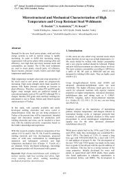
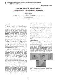
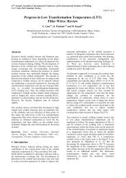
<strong>The</strong> <strong>Comparison</strong> <strong>of</strong> <strong>Microstructure</strong> <strong>and</strong> <strong>Mechanical</strong> <strong>Properties</strong> <strong>of</strong><br />
Flux-Cored Wires (FCW)<br />
H. D. Gençkan a , S. Keskinkılıç b , E. Saracoğlu c <strong>and</strong> M. Koçak d<br />
Gedik Welding Inc., Ankara Cad. No. 306, Şeyhli, 34913 Istanbul, Turkey<br />
a dgenckan@gedik.com.tr, b skeskinkilic@gedik.com.tr, c esaracoglu@gedik.com.tr, d mkocak@gedik.com.tr<br />
Abstract<br />
In this study, low carbon structural steels was welded<br />
using commercially available <strong>and</strong> newly developed flux<br />
cored arc welding (FCAW) consumables. <strong>The</strong> goal is to<br />
find relationships between microstructures <strong>and</strong><br />
mechanical properties. Through the experiments, St 52, 3<br />
steel was used as base metal. Also, 1.2 mm diameter <strong>of</strong><br />
different flux cored wires (FCWs) with rutile, basic <strong>and</strong><br />
metal cored types are used. <strong>The</strong> shielding gas 80% Ar +<br />
20% CO 2 mix <strong>and</strong> 100% CO 2 were chosen during the<br />
butt-welding for different type FCWs. <strong>The</strong> resulting<br />
weld joints were examined with respect to<br />
microstructure, tensile <strong>and</strong> Charpy-V impact toughness<br />
properties. <strong>The</strong> aim <strong>of</strong> this study is to examine<br />
microstructure-property relationships <strong>of</strong> the<br />
commercially available <strong>and</strong> newly developed prototype<br />
FCWs <strong>and</strong> determining the underlying factors for the<br />
superior mechanical properties for the prototype <strong>and</strong><br />
give an impetus for their further development. <strong>The</strong><br />
partial results <strong>of</strong> the ongoing investigations on the<br />
cooperative characterizations between six different<br />
FCWs are presented in this manuscript.<br />
Keywords: Flux-Cored Arc Welding (FCAW), rutile,<br />
basic <strong>and</strong> metal flux cored wires, mechanical properties,<br />
microstructure<br />
1. Introduction<br />
<strong>The</strong> use <strong>of</strong> FCWs for gas-shielded, arc welding has<br />
significantly increased over the past 30 years with their<br />
successful applications in welding <strong>of</strong> steel structures,<br />
shipbuilding, <strong>of</strong>fshore constructions, <strong>and</strong> petro-chemical<br />
<strong>and</strong> power generation industries [1].<br />
Flux cored wire welding (FCAW) has been compared to<br />
other welding processes <strong>and</strong> reported to have benefits<br />
like easy h<strong>and</strong>ling, higher productivity (lower cost) <strong>and</strong> a<br />
significant lower risk for defects like porosity <strong>and</strong> lack<br />
<strong>of</strong> fusion [2].<br />
Dem<strong>and</strong>s <strong>of</strong> higher levels <strong>of</strong> weld performance in service<br />
<strong>of</strong> the welded structures have challenged both fabricators<br />
<strong>and</strong> welding consumables manufacturers to develop<br />
innovative design <strong>and</strong> product solutions to generate <strong>and</strong><br />
maintain the high level <strong>of</strong> productivity <strong>and</strong> benefits <strong>of</strong><br />
innovative welding consumables [3].<br />
Recently, some reviews state that FCWs covers more<br />
than 30% <strong>of</strong> the total amount <strong>of</strong> arc welding materials<br />
[3]. <strong>The</strong>refore, significant effort has been made to<br />
develop FCW technologies to achieve better mechanical<br />
properties for welding <strong>of</strong> various types <strong>of</strong> steels used at<br />
sub-zero temperatures to higher service temperatures.<br />
This short paper presents the partial results <strong>of</strong> the ongoing<br />
investigations on the FCWs using method <strong>of</strong><br />
comparative investigations on the commercially<br />
available FCWs <strong>and</strong> newly developed prototype FCWs.<br />
<strong>The</strong> basic micro-mechanical characterization results are<br />
reported in this manuscript. It should be noted that G<br />
rutile wire <strong>and</strong> B basic FCWs are prototypes <strong>of</strong> GEDİK<br />
Welding. <strong>The</strong> other wires also have been obtained from<br />
different manufacturing companies.<br />
2. Background<br />
In this section, some basic information on the FCW<br />
types <strong>and</strong> technologies are provided. FCAW is a semiautomatic<br />
or automatic process which requires a<br />
continuously-fed consumable tubular electrode<br />
containing a flux <strong>and</strong> other alloying elements which<br />
enable some special welding features <strong>of</strong> the weld metal.<br />
Figure 1 shows the FCAW process [4].<br />
<strong>The</strong>re are several advantages <strong>of</strong> the FCWs compared to<br />
stick electrode <strong>and</strong> solid wires [5]. Namely,<br />
• Higher deposition rates than SMAW with good<br />
quality weld metal deposit<br />
• Compared to GMAW All position capability<br />
with less operator skill required<br />
• Deeper penetration than SMAW with spatterreduced<br />
welding behavior<br />
• Time saving process with semi-automatic or<br />
automatic <strong>and</strong> continuously feed from a spool<br />
• Minimum electrode wastage<br />
• Metallurgical benefits that can be gained from<br />
a flux<br />
19
FCW types are generally grouped as rutile, basic, metal,<br />
stainless <strong>and</strong> hard facing. <strong>The</strong>re are two basic process<br />
variants; self shielded FCAW (without shielding gas)<br />
<strong>and</strong> gas shielded FCAW (with shielding gas). <strong>The</strong><br />
difference between them stem from different fluxing<br />
agents in the consumables, which addresses different<br />
needs <strong>of</strong> different customer segments.<br />
Figure 1. <strong>The</strong> FCAW process<br />
As it is known, the primary function <strong>of</strong> the shielding gas<br />
is to protect the molten metal from atmospheric N 2 <strong>and</strong><br />
O 2 as the weld pool is being formed. <strong>The</strong> gas also<br />
promotes a stable arc <strong>and</strong> uniform metal transfer. It also<br />
affects the spatter rate <strong>and</strong> penetration pattern [6]. <strong>The</strong><br />
most common shielding gases: are C0 2 <strong>and</strong> Argon-CO 2<br />
mixtures for FCWs. Traditionally, CO 2 is used as a<br />
shielding gas due to its cheapness, but its use has been<br />
limited because <strong>of</strong> the problem <strong>of</strong> spatter, poor allposition<br />
performance [7].<br />
On the other h<strong>and</strong>, argon alone is also unsuitable for<br />
welding steel as it cannot sustain the desired arc stability<br />
<strong>and</strong> desired weld bead characteristics [8].<br />
<strong>The</strong> flux, which is contained within the core <strong>of</strong> the<br />
tubular electrode, melts during welding <strong>and</strong> shields the<br />
weld pool from the atmosphere.<br />
Flux contains substantial amounts <strong>of</strong> deoxidizing,<br />
denitrifying ingredients, arc stabilizers <strong>and</strong> alloying<br />
elements. <strong>The</strong>se are common core ingredients for<br />
FCWs. It is known that nitrogen <strong>and</strong> oxygen can cause<br />
porosity or brittleness while oxygen significantly affects<br />
the volume fraction <strong>and</strong> morphology <strong>of</strong> the inclusions so<br />
deoxidizers such as Mn <strong>and</strong> Si <strong>and</strong> denitrifiers such as Al<br />
are added to purify the weld metal. Furthermore, slag<br />
formers such as oxides <strong>of</strong> Ca, K, Si or Na are added to<br />
protect the molten weld pool from the atmosphere.<br />
Alloying elements Mo, Cr, C, Ni, Mn <strong>and</strong> V, are<br />
generally used, in a balanced manner to increase<br />
strength, ductility, hardness <strong>and</strong> toughness. Beside this,<br />
arc stabilizers such as Ka <strong>and</strong> Na, help to produce a<br />
smooth arc <strong>and</strong> reduce spatter [4]. <strong>The</strong> design <strong>of</strong> the<br />
chemical composition <strong>of</strong> the FCWs is also needs to<br />
comprise all those above listed generally known<br />
structures <strong>of</strong> the conventional welding consumables<br />
while taking into account <strong>of</strong> the special feature <strong>of</strong> the<br />
FCW <strong>and</strong> molten metal-transfer mechanism which<br />
differs from solid wires.<br />
3. Experimental Procedure<br />
<strong>The</strong> flux cored welding method were used for production<br />
<strong>of</strong> butt-welded plates <strong>of</strong> St 52,3 steel using six different<br />
types <strong>of</strong> FCWs using ceramic backing tape <strong>and</strong> mixed<br />
gas <strong>of</strong> 80% +20% CO 2 for basic <strong>and</strong> metal cored wire<br />
<strong>and</strong> 100% CO 2 for rutile FCWs.<br />
<strong>The</strong> wires used in the study are 1.2 mm diameter <strong>and</strong><br />
conform to the AWS A5.20 specifications. Rutile wires<br />
have E71-T1 type, Basic <strong>and</strong> Metal wires have also E71-<br />
T5 type. Table 1 shows the list <strong>and</strong> types <strong>of</strong> the<br />
consumables wires.<br />
Table 1. Characteristics <strong>of</strong> flux-cored consumables<br />
Characteristic <strong>of</strong> consumables<br />
Welding Deposit Wire Type<br />
Diameter (mm)<br />
G Wire Rutile 1,2<br />
K Wire Rutile 1,2<br />
S Wire Rutile 1,2<br />
E Wire Rutile 1,2<br />
B Wire Basic 1,2<br />
M Wire Metal 1,2<br />
Test pieces were cut from welded plates <strong>of</strong> 300 mm<br />
(width) ×500 mm (length) ×15mm (thickness). This base<br />
material with a 60º V-shaped groove was used <strong>and</strong><br />
multipass (5 passes) welding procedure was carried out<br />
in flat position with the interpass temperature <strong>of</strong> about<br />
150ºC.<br />
Figure 2a. <strong>The</strong> plan <strong>of</strong> cutting for mechanical tests; tensile samples<br />
(1), bending samples (2), macro <strong>and</strong> micrography samples (3) <strong>and</strong><br />
Charpy V-Notch samples (4).<br />
<strong>The</strong> chemical analyses <strong>of</strong> weld metals, which were<br />
welded with different type FCWs, are given in Table 2.<br />
During the welding, semi-automatic welding machine<br />
was used.<br />
20
63 rd Annual Assembly & International Conference <strong>of</strong> the International Institute <strong>of</strong> Welding<br />
11-17 July 2010, Istanbul, Turkey<br />
AWST-10/100<br />
Figure 4. <strong>The</strong> top side <strong>of</strong> one <strong>of</strong> the FCWs<br />
4. Results <strong>and</strong> Discussion<br />
Figure 2b. Test specimens<br />
Table 2. Chemical compositions <strong>of</strong> the weld metals <strong>and</strong> base metal<br />
Elements<br />
Base<br />
Metal<br />
G<br />
Wire<br />
K<br />
Wire<br />
Wt. (%)<br />
Rutile<br />
S<br />
Wire<br />
E<br />
Wire<br />
Metal Basic<br />
M<br />
Wire<br />
B<br />
Wire<br />
C 0.162 0.039 0.034 0.031 0.05 0.048 0.071<br />
Si 0.293 0.428 0.73 0.39 0.51 0.589 0.55<br />
Mn 1.37 1.29 1.28 1.09 1.22 1.35 1.464<br />
S 0.0045 0.003 0.0074 0.003 0.02 0.024 0.010<br />
Cr 0.041 0.024 0.024 0.021 0.03 0.021 0.030<br />
Mo 0.013 - 0.0038 - 0.04 - 0.013<br />
Cu 0.049 0.035 0.0271 0.068 0.02 0.061 0.060<br />
V 0.0768 0.015 0.0216 0.014 0.02 - 0.006<br />
Ni 0.04 0.009 0.057 0.192 0.46 0.007 0.040<br />
Fe 97.922 98.163 97.863 98.18 97.63 99.25 98.25<br />
<strong>The</strong> mechanical <strong>and</strong> microstructural properties (tensile,<br />
impact toughness, bending, microhardness <strong>and</strong><br />
micrography studies) <strong>of</strong> FCWs were tested on butt-weld<br />
metal. Test temperature has been chosen to be 20º C.<br />
<strong>The</strong> tensile strength, bending, micro hardness <strong>and</strong> impact<br />
toughness results from the butt-weld test can be seen in<br />
Table 3.<br />
Table 3. <strong>Mechanical</strong> properties <strong>of</strong> the weld metals<br />
FCW Types<br />
Rutile<br />
Basic<br />
Metal<br />
Tensile<br />
Strength<br />
(MPa)<br />
Bend<br />
Test<br />
G<br />
wire 581 Ok<br />
K<br />
wire 550 Ok<br />
S<br />
Wire 550 Ok<br />
E<br />
Wire 551 Ok<br />
B<br />
wire 603 Ok<br />
M<br />
wire 513 Ok<br />
Impact<br />
Energy (J)<br />
20ºC - 20ºC<br />
80<br />
110<br />
122<br />
46<br />
61<br />
77<br />
85<br />
108<br />
132<br />
94<br />
104<br />
108<br />
158<br />
159<br />
166<br />
126<br />
132<br />
144<br />
32<br />
34<br />
80<br />
14<br />
18<br />
21<br />
32<br />
40<br />
46<br />
22<br />
30<br />
36<br />
88<br />
106<br />
110<br />
63<br />
71<br />
80<br />
Micro<br />
hardness<br />
(Hv)<br />
255<br />
258<br />
287<br />
306<br />
268<br />
272<br />
<strong>The</strong> microstructures <strong>of</strong> the welding materials were<br />
examined by Optical Microscope after polishing <strong>and</strong><br />
etching with Nital 10%. Figure 5 shows the<br />
macrostructure <strong>of</strong> G wire with 500 magnifications (50X).<br />
Figure 6 a, b, c, d, e, f show the microstructure <strong>of</strong> rutile,<br />
basic <strong>and</strong> metal FCWs.<br />
Figure 3. Experimental setup by using semi-automatic welding<br />
procedure<br />
During the welding, the voltage was held at 30 V. A<br />
constant wire-feeding rate <strong>of</strong> 8,5 m/min was maintained<br />
for all the welds .<strong>The</strong> welding current was in the range <strong>of</strong><br />
240-250 A. 170-190 A, 23 V <strong>and</strong> 5,5 m/min wire speed<br />
were used for the root passes. Top weld <strong>of</strong> the basic<br />
FCW is shown in Figure 4.<br />
Figure 5. <strong>The</strong> cross-section <strong>of</strong> the weld joints i.e. G wire<br />
21
As shown in the microstructures K wire has exhibited<br />
coarser grains compared to other FCWs. E wire has also<br />
fine-grains.<br />
Beside this, it is seen some inclusions in K wire. It must<br />
be pointed out that, O 2 <strong>and</strong> N 2 levels have not yet been<br />
carried out.<br />
Figure 6a. <strong>The</strong> microstructure <strong>of</strong> G (Rutile)<br />
FCW<br />
Figure 6d. <strong>The</strong> microstructure <strong>of</strong> E (Rutile)<br />
FCW<br />
Figure 6b. <strong>The</strong> microstructure <strong>of</strong> K (Rutile)<br />
FCW<br />
Figure 6e. <strong>The</strong> microstructure <strong>of</strong> B (Basic)<br />
FCW<br />
Figure 6c. <strong>The</strong> microstructure <strong>of</strong> S (Rutile)<br />
FCW<br />
Figure 6f. <strong>The</strong> microstructure <strong>of</strong> M (Metal)<br />
FCW<br />
22
63 rd Annual Assembly & International Conference <strong>of</strong> the International Institute <strong>of</strong> Welding<br />
11-17 July 2010, Istanbul, Turkey<br />
AWST-10/100<br />
Among the rutile FCWs, G wire has the highest strength<br />
with 581 MPa. <strong>The</strong> other K, S <strong>and</strong> E rutile wires have<br />
tensile strength <strong>of</strong> 550 MPa, 550 MPa <strong>and</strong> 551 MPa,<br />
respectively. Beside this, B wire which is basic FCW has<br />
the highest tensile strength <strong>of</strong> 603 MPa. As shown in the<br />
Table 3, M wire has the lowest strength value with 513<br />
MPa. Figure 7 shows the tensile specimen ruptured from<br />
base metal <strong>of</strong> S wire <strong>and</strong> Figure 8 shows tensile strength<br />
values <strong>of</strong> the wires.<br />
Figure 9b. Root <strong>and</strong> facial images <strong>of</strong> one <strong>of</strong> the wires<br />
<strong>The</strong> impact toughness <strong>of</strong> the weld metals was evaluated<br />
by Charpy impact testing. Impact test results are seen in<br />
Table 1 <strong>and</strong> Figure 10 also shows the values <strong>of</strong> Charpy<br />
V-Notches parallel to the weld axis (Figure 2a) tested at<br />
-20ºC <strong>and</strong> 20 ºC for G, K, S, E, B <strong>and</strong> M FCWs.<br />
Figure 7. Tensile specimen <strong>of</strong> wire ruptured from base metal as a<br />
sample<br />
<strong>The</strong> charpy impact values at 20ºC <strong>and</strong> -20ºC indicate that<br />
maximum toughness was obtained for B wire, with 158<br />
joule at 20ºC <strong>and</strong> 88 joule at -20ºC. It is attributed to the<br />
low hardness showed in Table 3. E wire has also very<br />
low impact energy compared to other wires. It is known<br />
that when the hardness value increase, the impact<br />
toughness decreases. Thus, it is concluded that E wire,<br />
which has high hardness strength, shows brittle character<br />
so impact toughness decreases. E wire’s fine grain size<br />
also supports its high hardness. M wire also has the<br />
second highest value with 63 joule at -20ºC.<br />
As shown in the Table 3, K wire with 14 joule <strong>and</strong> G<br />
wire with 32 joule at -20 ºC have the lowest toughness<br />
value. It appears that the toughness values obtained one<br />
lower than the values which could be generally<br />
generated for low carbon structural steels.<br />
Figure 8. Tensile strength values <strong>of</strong> FCWs<br />
Bending results were given as bendability. It has not<br />
observed any problems during the bending tests <strong>of</strong> the<br />
wires. Figure 9a shows the bending specimen <strong>and</strong><br />
bending test machine. Figure 9b shows facial <strong>and</strong> root<br />
bend images <strong>of</strong> one <strong>of</strong> the wires.<br />
In this study, st 52, 3 grade steel was used <strong>and</strong> this has<br />
caused some degree <strong>of</strong> dilution into the weld metal <strong>and</strong><br />
has adversely affected the properties <strong>of</strong> the weld metal<br />
toughness values. However, the values obtained for the<br />
comparison reason can still be used for comparing the<br />
weldments.<br />
Figure 9a. Bending specimen image <strong>and</strong> bending test<br />
Figure 10. Charpy impact values <strong>of</strong> FCWs<br />
23
Different FCWs’ hardnesses were performed on the<br />
samples with a Vickers indenter with a load 300 g. force.<br />
Figure 11 shows the hardness values <strong>of</strong> FCWs. As<br />
shown in figure, E wire has the highest hardness with<br />
306 Hv among the all FCWs.<br />
In this study, FCWs in rutile, basic <strong>and</strong> metal-cored<br />
types were used to produce butt-joints <strong>and</strong> the welds<br />
were investigated in terms <strong>of</strong> microstructural features<br />
<strong>and</strong> mechanical properties to find out the microstructureproperty<br />
relationships. Commercially available FCWs<br />
(from different manufacturing companies <strong>and</strong> countries)<br />
were used <strong>and</strong> their results are compared with prototype<br />
wires which are currently in development.<br />
Microstructural features were examined using optical<br />
micrograpical examinations while Charpy-V toughness<br />
was obtained both at RT <strong>and</strong> -20ºC temperatures. Tensile<br />
tests were conducted at RT.<br />
Following conclusions could be made for the results<br />
obtained:<br />
For all FCWs, no major weldability problem<br />
was observed <strong>and</strong> all weld joints were produced<br />
without any weld defects.<br />
Tensile strength values <strong>of</strong> all weld metals were<br />
above 510 MPa while Charpy-V toughness<br />
values at RT were above 80 Joule except FCwire<br />
K (46 Joule). This rutile K wire has also<br />
produced lowest impact toughness value (14<br />
Joule) at -20ºC. <strong>The</strong> E wire has produced 22<br />
Joule Charpy impact energy at -20ºC while it<br />
has exhibited highest hardness values <strong>of</strong> 306.<br />
<strong>The</strong> reason <strong>of</strong> low impact toughness values<br />
needs to be clarified. Hence, oxygen levels are<br />
currently examined <strong>and</strong> also new welds are<br />
being made for new sets <strong>of</strong> tests.<br />
Figure 11. Hardness values <strong>of</strong> FCWs<br />
It is evident from the data presented in Table 2, Nickel<br />
content are obtained for weld metal is high in E wire<br />
since higher nickel content supports the highest hardness<br />
values. Nickel content <strong>of</strong> E wire is about % 0.46, G, K,<br />
S, B <strong>and</strong> M wire’s nickel contents are 0.009, 0.057,<br />
0.192, 0.04 <strong>and</strong> 0.007 respectively. As reported by Kang<br />
et al. [9] for a low-Mn composition, Ni addition<br />
increases hardness without sacrificing impact toughness<br />
much whereas for a high Mn composition (1.6 % Mn),<br />
Ni deteriorates the impact toughness seriously.<br />
Furthermore, E wire has fine grain size. This property<br />
makes the wire harder. <strong>The</strong> lowest hardness value is G<br />
wire with 255 Hv <strong>and</strong> K wire’s hardness value is also<br />
low compared to others. Coarse grain <strong>and</strong> inclusions in<br />
weld metal keep the G <strong>and</strong> K wire’s hardness low. B <strong>and</strong><br />
M wire’s hardnesses were found approximately 270 Hv.<br />
5. Conclusions<br />
Weld Metal<br />
References<br />
<strong>The</strong> microstructure <strong>of</strong> the K wire has exhibited<br />
coarse grains while E wire assumed to have<br />
higher content <strong>and</strong> coarser non-metallic<br />
inclusions to cause lower impact toughness<br />
properties. <strong>The</strong> measurements <strong>of</strong> the oxygen<br />
levels <strong>and</strong> SEM investigations <strong>of</strong> the<br />
morphology <strong>of</strong> inclusions <strong>and</strong> fracture surfaces<br />
<strong>of</strong> the welds are in progress.<br />
[1] Pitrun M., Nolan D., Dunne D., “Diffusiable Hydrogen Content in<br />
Rutile Flux-cored Arc Welds as a Function <strong>of</strong> the Welding<br />
Parameters”, Welding In the World, Vol 48, n ½, 2004.<br />
[2] Posh G., Baumgartner S., Fiedler M., “GMA-Welding <strong>of</strong> creep<br />
resistant steels with flux cored wires (FCAW): perspectives <strong>and</strong><br />
limitations”, IIW International Conference on Advances in<br />
Welding <strong>and</strong> Allied Technologies, 2009.<br />
[3] Marie A., Zhang J. , “Self-Shielded Flux Cored Welding for Steel<br />
Constructions- Productivity <strong>and</strong> Performance”, IFWT 2006.<br />
[4] “Welding, Brazing <strong>and</strong> Soldering” ASM H<strong>and</strong>book, Vol 6, 1993.<br />
[5] Kannan T., Murugan N.,” Effect <strong>of</strong> flux cored arc welding process<br />
parameters on duplex stainless steel clad quality”, Journals <strong>of</strong><br />
Materials Processing Technology, 2006.<br />
[6] Liao M. T. <strong>and</strong> Chen W. J., “A <strong>Comparison</strong> <strong>of</strong> Gas Metal Arc<br />
Welding with Flux-Cored Wires <strong>and</strong> Solid Wires Using Shielding<br />
Gas”, <strong>The</strong> International Journal <strong>of</strong> Advanced Manufacturing<br />
Technology, 1999.<br />
[7] Varga T, Konkoly T, Straube H. “Investigation on microstructure,<br />
toughness, <strong>and</strong> defect tolerence <strong>of</strong> gas metal arc weld metal”., IIW<br />
Document, X-1205-90.<br />
[8] Mukhopadhyay S., Pal T.K., “Effect <strong>of</strong> shielding gas mixture on<br />
gas metal arc welding <strong>of</strong> HSLA steel using solid <strong>and</strong> flux-core<br />
wires”, <strong>The</strong> International Journal <strong>of</strong> Advanced Manufacturing<br />
Technology,29: 262-268, 2006.<br />
[9] Coronado J.J., Ceron C.,“Fracture mechanisms <strong>of</strong> CTOD samples<br />
<strong>of</strong> submerged <strong>and</strong> flux cored arc welding”, <strong>The</strong>oretical <strong>and</strong><br />
Applied Fracture Mechanics,2010.<br />
24