Z855 – Z875 Z895 – Z8125 SERIES
Z855 – Z875 Z895 – Z8125 SERIES
Z855 – Z875 Z895 – Z8125 SERIES

Create successful ePaper yourself
Turn your PDF publications into a flip-book with our unique Google optimized e-Paper software.
8” SUBMERSIBLE<br />
ELECTRIC PUMPS<br />
50 Hz<br />
<strong>Z855</strong> <strong>–</strong> <strong>Z875</strong><br />
<strong>Z895</strong> <strong>–</strong> <strong>Z8125</strong> <strong>SERIES</strong><br />
EDITION 03-2006
INDEX<br />
Z8 Series Specifications............................................................................ 3<br />
Table of Materials .................................................................................... 4<br />
Hydraulic Performance Range, Z8 Series 50 Hz ....................................... 5<br />
Pump Cross-Section and List of Main Components .................................. 26<br />
L6C Series Motors ................................................................................... 27<br />
MC8 Series Motors.................................................................................. 31<br />
MC10 Series Motors................................................................................ 33<br />
AISI 316 F6 Series Motors ....................................................................... 35<br />
FW8 Series Motors .................................................................................. 37<br />
FW10 Series Motors ................................................................................ 39<br />
Accessories.............................................................................................. 41<br />
Technical Appendix.................................................................................. 61
8”<br />
Submersible<br />
Electric<br />
Pumps<br />
<strong>Z855</strong><br />
<strong>Z875</strong><br />
<strong>Z895</strong><br />
<strong>Z8125</strong><br />
Series<br />
MARKET SECTORS<br />
AGRICULTURAL, INDUSTRIAL<br />
APPLICATIONS<br />
• Water supply from deep wells.<br />
• Pressure boosting and water distribution in civil and<br />
industrial systems.<br />
• Supply of surge tanks and reservoirs.<br />
• Firefighting and washing systems.<br />
• Water level control.<br />
• Irrigation.<br />
• Mining.<br />
SPECIFICATIONS<br />
PUMP<br />
Delivery: up to 180 m3 /h.<br />
Head: up to 550 m.<br />
• Maximum pump overall diameter<br />
(2 cable covers included): 198 mm<br />
for all versions.<br />
• Maximum electric pump immersion<br />
depth:<br />
250 m with L6C motors,<br />
40 m with MC8 and MC10 motors,<br />
standard configuration (with lip<br />
seal); version with mechanical seal<br />
available on request (max.<br />
immersion depth 350 m).<br />
• Maximum permissible quantity of<br />
suspended sand: 100 g/m 3 .<br />
• Standard delivery outlet:<br />
Rp 5” for all versions.<br />
• Motor power: from 5.5 to 150 kW<br />
MOTOR<br />
• L6C motor: three-phase water-filled<br />
asynchronous motors with<br />
hermetically sealed stator<br />
• MC8 and MC10 rewindable threephase<br />
asynchronous motors with<br />
water-filled winding.<br />
• Three-phase version:<br />
L6C: from 3 to 37 kW 380-415V, 50Hz<br />
MC8: from 30 to 92 kW 380-415V,<br />
50Hz<br />
MC10: from 92 to 150 kW 380-415V,<br />
50Hz<br />
• Maximum supply voltage variations:<br />
L6C 400V ±10%,<br />
MC8, MC10 400V +6% -10%.<br />
• PVC windings for MC8 and MC10<br />
motors.<br />
• Horizontal operation:<br />
L6C up to 37 kW provided that the<br />
associated pump can apply an axial<br />
thrust of at least 250 N on the<br />
entire operating field.<br />
MC8 and MC10 available on request<br />
for all versions<br />
• Maximum number of starts per<br />
hour: 25 (L6C), 15 (MC8) and 10<br />
(MC10).<br />
• Maximum temperature of water in<br />
contact with motor: 35°C (L6C),<br />
25°C (MC8 and MC10).<br />
CONSTRUCTION<br />
FEATURES<br />
PUMP<br />
• Robust and lightweight, easy to<br />
maintain and corrosion resistant in<br />
non-aggressive environments.<br />
<strong>–</strong> Impellers and diffusers<br />
made of stainless steel.<br />
<strong>–</strong> Delivery casing made of<br />
stainless steel.<br />
<strong>–</strong> Non-return valve made of<br />
stainless steel, with<br />
integrated spring.<br />
<strong>–</strong> Suction support made of<br />
stainless steel.<br />
<strong>–</strong> Shaft made of stainless<br />
steel.<br />
• The guide bearings and wear rings<br />
ensure high resistance to wear and<br />
guarantee the constant and<br />
long-lasting performance of<br />
the hydraulic characteristics.<br />
• Coupling and flange mounting<br />
dimensions meet NEMA standards.<br />
• ZR8 version in DUPLEX<br />
stainless steel is also available.<br />
OPTIONAL FEATURES<br />
MOTOR<br />
Different voltages and frequencies.<br />
High temperature versions.<br />
• MC8 and MC10 for horizontal<br />
installation.<br />
ACCESSORIES<br />
Coupling flange.<br />
• Panels.<br />
Cables.<br />
3
TABLE OF MATERIALS Z8<br />
COMPONENT<br />
Delivery head / Valve Casing<br />
Valve<br />
Valve seat<br />
Valve spring<br />
Diffuser / Bowl<br />
Diffuser O-Ring<br />
Impeller<br />
Taperlock<br />
Wear ring<br />
Lower support / Suction Casing<br />
Suction strainer<br />
Pump shaft<br />
Coupling<br />
Bearing bush<br />
Thrust Bearing<br />
Screw, stud, nut<br />
Cable protection<br />
MATERIAL<br />
TABLE OF MATERIALS ZR8<br />
COMPONENT<br />
Delivery head / Valve Casing<br />
Valve<br />
Valve seat<br />
Valve spring<br />
Diffuser / Bowl<br />
Diffuser O-Ring<br />
Impeller<br />
Taperlock<br />
Wear ring<br />
Lower support / Suction Casing<br />
Suction strainer<br />
Pump shaft<br />
Coupling<br />
Bearing bush<br />
Thrust Bearing<br />
Screw, stud, nut<br />
Cable protection<br />
IDENTIFICATION CODES<br />
Z R 8 9 5 1 0 / 3 A <strong>–</strong> MC8<br />
Motor code<br />
EUROPE<br />
DESIGNATION<br />
Stainless steel EN 10213-4-GX5CrNi19-10 (1.4308) A744-CF 8<br />
Stainless steel EN 10213-4-GX5CrNi19-10 (1.4308) A744-CF 8<br />
NBR 90<br />
Stainless steel EN 10088-1-X5CrNiMo17-12-2 (1.4401) AISI 316<br />
Stainless steel EN 10213-4-GX5CrNi19-10 (1.4308) A744-CF 8<br />
NBR 70<br />
Stainless steel EN 10213-4-GX5CrNi19-10 (1.4308) A744-CF 8<br />
Duplex stainless steel EN 10088-1-X2CrNiMoN22-5-3 (1.4462) A276/A790-S31803<br />
POM (DELRIN ® )<br />
Stainless steel EN 10213-4-GX5CrNi19-10 (1.4308) A744-CF 8<br />
Stainless steel DIN 17440-X6CrNiMoTi17-12-2 (1.4571) AISI 316Ti<br />
Stainless steel EN 10088-1-X17CrNi16-2 (1.4057) AISI 431<br />
Stainless steel EN 10088-1-X17CrNi16-2 (1.4057) AISI 431<br />
EPDM + LOXAMID ®<br />
PTFE + 25% carbon<br />
Stainless steel ISO 3506-1/2 A4-70 AISI 316<br />
Stainless steel EN 10088-1-X5CrNi18-10 (1.4301) AISI 304<br />
MATERIAL<br />
DESIGNATION<br />
EUROPE<br />
USA<br />
USA<br />
z8-2p50_c_tm<br />
Duplex stainless steel EN 10213-4-GX2CrNiMoCuN25-6-3-3 (1.4517)<br />
Duplex stainless steel EN 10213-4-GX2CrNiMoCuN25-6-3-3 (1.4517)<br />
NBR 90<br />
Hastelloy C4 DIN17744-NiMo16Cr16Ti (2.4610) N06455<br />
Duplex stainless steel EN 10213-4-GX2CrNiMoCuN25-6-3-3 (1.4517)<br />
NBR 70<br />
Duplex stainless steel EN 10213-4-GX2CrNiMoCuN25-6-3-3 (1.4517)<br />
Duplex stainless steel EN 10088-1-X2CrNiMoN22-5-3 (1.4462) A276/A790-S31803<br />
POM (DELRIN ® )<br />
Duplex stainless steel EN 10213-4-GX2CrNiMoCuN25-6-3-3 (1.4517)<br />
Stainless steel EN 10088-1X1NiCrMoCu25-20-5 (1.4539) AISI 904L<br />
Duplex stainless steel EN 10088-1-X2CrNiMoN22-5-3 (1.4462) A276/A790-S31803<br />
Duplex stainless steel EN 10088-1-X2CrNiMoN22-5-3 (1.4462) A276/A790-S31803<br />
EPDM + LOXAMID ®<br />
PTFE + 25% carbon<br />
Duplex stainless steel EN 10088-1-X2CrNiMoN22-5-3 (1.4462) A276/A790-S31803<br />
Stainless steel EN 10088-1X1NiCrMoCu25-20-5 (1.4539) AISI 904L<br />
zr8-2p50_a_tm<br />
Reduction type<br />
Number of reduced stages<br />
Number of stages<br />
Flow rate in m 3 /h<br />
Type of pump (R = DUPLEX version)<br />
Blank = 50 Hz<br />
EXAMPLE: ZR8 9510/3A - MC8<br />
6 = 60 Hz<br />
8” electric pump, 50 Hz, made of DUPLEX, flow rate 95 m 3 /h, 10 stages including 3 reduced ones, coupled to an 8” MC8 motor.<br />
4
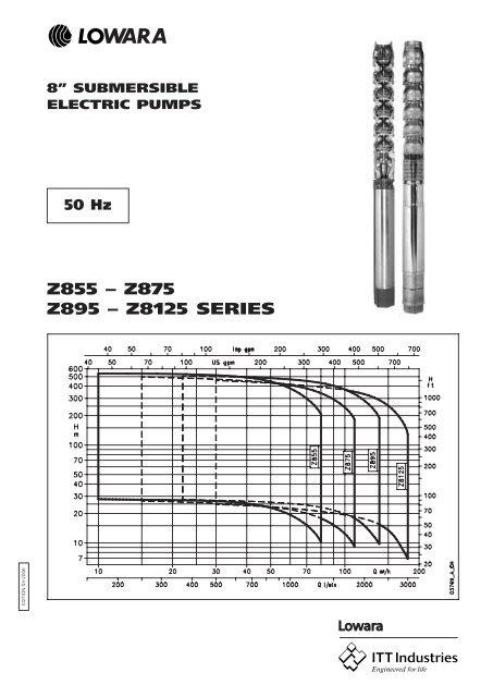
Z8 <strong>SERIES</strong><br />
OPERATING CHARACTERISTICS AT 50 Hz<br />
5
<strong>Z855</strong> <strong>SERIES</strong>, 1 TO 7 STAGES<br />
OPERATING CHARACTERISTICS AT 50 Hz<br />
Q = DELIVERY<br />
PUMP RATED l/min 0 167 500 833 1217 1333<br />
TYPE POWER m 3 /h 0 10 30 50 73 80<br />
H = TOTAL HEAD METRES COLUMN OF WATER<br />
kW<br />
<strong>Z855</strong> 01 5,5 28,7 28 27 23 14 10,2<br />
<strong>Z855</strong> 02/2A 7,5 45,7 44,4 43 35 14,9<br />
<strong>Z855</strong> 02/1A 7,5 51,3 49,9 48 40 20,5<br />
<strong>Z855</strong> 02 9,3 57 55,6 53 45 27 19,7<br />
<strong>Z855</strong> 03/2A 11 74,2 72,1 69 57 27,7<br />
<strong>Z855</strong> 03 15 86,1 83,9 80 69 41 30,7<br />
<strong>Z855</strong> 04/2A 15 102,7 99,9 96 79 41<br />
<strong>Z855</strong> 04 18,5 114,6 111,7 107 91 55 40,7<br />
<strong>Z855</strong> 05/3A 18,5 125,6 122,2 117 97 49<br />
<strong>Z855</strong> 05/2A 22 132,3 128,8 124 104 56,7<br />
<strong>Z855</strong> 05 22 143,5 139,8 134 114 68 50,5<br />
<strong>Z855</strong> 06/2A 30 160,7 156,6 150 127 70,9<br />
<strong>Z855</strong> 06 30 172 167,6 160 137 83 61,3<br />
<strong>Z855</strong> 07/2A 30 188,6 183,6 176 148 82,3<br />
<strong>Z855</strong> 07 30 199,7 194,5 186 158 93 68,8<br />
DIMENSIONS AND WEIGHTS<br />
ELECTRO-<br />
PUMP<br />
TYPE<br />
DIMENSIONS (mm)<br />
z855-2p50_a_th<br />
ELECTRO-<br />
PUMP<br />
WEIGHT<br />
A (4) C (1) M Tmin (2) kg (3)<br />
<strong>Z855</strong> 01-L6C 1191 200 140 1631 70<br />
<strong>Z855</strong> 02/2A-L6C 1355 200 140 1660 81<br />
<strong>Z855</strong> 02/1A-L6C 1355 200 140 1660 81<br />
<strong>Z855</strong> 02-L6C 1380 200 140 1685 84<br />
<strong>Z855</strong> 03/2A-L6C 1560 200 140 1730 97<br />
<strong>Z855</strong> 03-L6C 1615 200 140 1785 103<br />
<strong>Z855</strong> 04/2A-L6C 1750 200 140 1785 112<br />
<strong>Z855</strong> 04-L6C 1825 200 140 1860 119<br />
<strong>Z855</strong> 05/3A-L6C 1960 200 140 1860 128<br />
<strong>Z855</strong> 05/2A-L6C 2020 200 140 1920 134<br />
<strong>Z855</strong> 05-L6C 2020 200 140 1920 134<br />
<strong>Z855</strong> 06/2A-L6C 2285 200 140 2050 155<br />
<strong>Z855</strong> 06-L6C 2285 200 140 2050 155<br />
<strong>Z855</strong> 07/2A-L6C 2420 200 140 2050 164<br />
<strong>Z855</strong> 07-L6C 2420 200 140 2050 164<br />
z855-2p50_a_td<br />
1) Max electric-pump diameter with 2 motor cables included.<br />
In case of 1 motor cable C = 198 mm with L6C motor.<br />
2) T min valid only for max flow speed of 4,2 m/s.<br />
For higher speeds please contact our sales network.<br />
3) Without cables.<br />
4) For pumps without non-return valve, reduce dimension A by 110 mm, and reduce weight by 4 kg.<br />
6
<strong>Z855</strong> <strong>SERIES</strong>, 1 TO 7 STAGES<br />
OPERATING CHARACTERISTICS AT 50 Hz<br />
The flow resistance of the non-return valve has been considered.<br />
These performances are valid for liquids with density ρ = 1,0 kg/dm 3 and kinematic viscosity υ = 1 mm 2 /sec.<br />
7
<strong>Z855</strong> <strong>SERIES</strong>, 8 TO 19 STAGES<br />
OPERATING CHARACTERISTICS AT 50 Hz<br />
Q = DELIVERY<br />
PUMP RATED l/min 0 167 500 833 1217 1333<br />
TYPE POWER m 3 /h 0 10 30 50 73 80<br />
H = TOTAL HEAD METRES COLUMN OF WATER<br />
kW<br />
<strong>Z855</strong> 08/2A 37 217 211,5 202,8 171 96,1<br />
<strong>Z855</strong> 08 37 228,3 222,5 212,7 181 107,3 79,4<br />
<strong>Z855</strong> 09/2A 37 244,8 238,3 227,8 191,2 106,8<br />
<strong>Z855</strong> 09 44 260,6 254,2 244,3 210,6 128,5 96,9<br />
<strong>Z855</strong> 10/2A 44 277,5 270,5 260,1 221,5 128,4<br />
<strong>Z855</strong> 10 44 288,8 281,7 270,3 231,9 140,2 105,2<br />
<strong>Z855</strong> 11/2A 52 305,6 298 286,6 244,8 143,2<br />
<strong>Z855</strong> 11 52 316,9 309,2 296,8 255,4 155,4 116,9<br />
<strong>Z855</strong> 12 55 346,6 338,3 324,8 279,8 170,5 128,5<br />
<strong>Z855</strong> 13 59 375,3 366,1 351,3 302,3 183,7 138,2<br />
<strong>Z855</strong> 14 66 404,5 394,7 379,1 326,6 198,9 149,9<br />
<strong>Z855</strong> 15 66 432,8 422,2 404,9 348 210,9 158,4<br />
<strong>Z855</strong> 16 75 461,6 450,3 432,1 372,2 226,5 170,5<br />
<strong>Z855</strong> 17 92 491,8 479,8 461,2 398,8 244,6 185<br />
<strong>Z855</strong> 18 92 520 507,3 487,4 420,8 257 194<br />
<strong>Z855</strong> 19 92 551,2 538 517 446,3 273,5 206,9<br />
DIMENSIONS AND WEIGHTS<br />
ELECTRO-<br />
PUMP<br />
TYPE<br />
DIMENSIONS (mm)<br />
z855a-2p50_a_th<br />
ELECTRO-<br />
PUMP<br />
WEIGHT<br />
A (4) C (1) M Tmin (2) kg (3)<br />
<strong>Z855</strong> 08/2A-L6C 2685 200 140 2180 186<br />
<strong>Z855</strong> 08-L6C 2685 200 140 2180 186<br />
<strong>Z855</strong> 09/2A-L6C 2820 200 140 2180 194<br />
<strong>Z855</strong> 09-MC8 2835 203,3 192 2195 276<br />
<strong>Z855</strong> 10/2A-MC8 2970 203,3 192 2195 284<br />
<strong>Z855</strong> 10-MC8 2970 203,3 192 2195 284<br />
<strong>Z855</strong> 11/2A-MC8 3195 203,3 192 2285 313<br />
<strong>Z855</strong> 11-MC8 3195 203,3 192 2285 313<br />
<strong>Z855</strong> 12-MC8 3370 203,3 192 2325 328<br />
<strong>Z855</strong> 13-MC8 3555 203,3 192 2375 347<br />
<strong>Z855</strong> 14-MC8 3780 203,3 192 2465 374<br />
<strong>Z855</strong> 15-MC8 3915 203,3 192 2465 382<br />
<strong>Z855</strong> 16-MC8 4140 203,3 192 2555 408<br />
<strong>Z855</strong> 17-MC8 4475 203,3 192 2755 455<br />
<strong>Z855</strong> 18-MC8 4610 203,3 192 2755 463<br />
<strong>Z855</strong> 19-MC8 4745 203,3 192 2755 472<br />
z855a-2p50_a_td<br />
1) Max electric-pump diameter with 2 motor cables included.<br />
In case of 1 motor cable C = 198 mm with L6C motor.<br />
C = 201,5 mm with MC8 motor.<br />
2) T min valid only for max flow speed of 4,2 m/s.<br />
For higher speeds please contact our sales network.<br />
3) Without cables.<br />
4) For pumps without non-return valve, reduce dimension A by 110 mm, and reduce weight by 4 kg.<br />
8
<strong>Z855</strong> <strong>SERIES</strong>, 8 TO 19 STAGES<br />
OPERATING CHARACTERISTICS AT 50 Hz<br />
The flow resistance of the non-return valve has been considered.<br />
These performances are valid for liquids with density ρ = 1,0 kg/dm 3 and kinematic viscosity υ = 1 mm 2 /sec.<br />
9
<strong>Z875</strong> <strong>SERIES</strong>, 1 TO 6 STAGES<br />
OPERATING CHARACTERISTICS AT 50 Hz<br />
Q = DELIVERY<br />
PUMP RATED l/min 0 250 700 1167 1700 1833<br />
TYPE POWER m 3 /h 0 15 42 70 102 110<br />
H = TOTAL HEAD METRES COLUMN OF WATER<br />
kW<br />
<strong>Z875</strong> 01 5,5 28,9 26,9 24,2 20,1 11,8 9,2<br />
<strong>Z875</strong> 02/2A 7,5 44,1 42,1 38,2 29,3 11,3<br />
<strong>Z875</strong> 02/1A 9,3 50,8 48 43,3 34,7 17,6<br />
<strong>Z875</strong> 02 11 57,9 54,1 48,7 40,5 23,9 18,6<br />
<strong>Z875</strong> 03/3A 11 66,1 63,1 57,2 43,7 16,9<br />
<strong>Z875</strong> 03/2A 15 73,5 69,7 63,3 50,4 24<br />
<strong>Z875</strong> 03/1A 15 80,1 75,3 68 55,3 29,8<br />
<strong>Z875</strong> 03 18,5 87,5 81,7 73,9 61,8 37 29,1<br />
<strong>Z875</strong> 04/2A 18,5 102,3 96,5 87,4 70,3 35,6<br />
<strong>Z875</strong> 04 22 116,5 108,8 98,1 81,8 48,8 38,1<br />
<strong>Z875</strong> 05/3A 22 124,7 117,9 106,7 85,2 41,4<br />
<strong>Z875</strong> 05/2A 30 132,1 124,4 112,9 92,1 49,3<br />
<strong>Z875</strong> 05 30 145,3 135,8 122,5 102,3 61 47,7<br />
<strong>Z875</strong> 06/2A 30 160 150,4 135,9 110,6 59,7<br />
<strong>Z875</strong> 06/1A 30 166,5 156 140,6 115,5 65,8<br />
<strong>Z875</strong> 06 37 174,2 162,8 147,1 122,7 73,1 57,2<br />
DIMENSIONS AND WEIGHTS<br />
ELECTRO-<br />
PUMP<br />
TYPE<br />
DIMENSIONS (mm)<br />
z875-2p50_a_th<br />
ELECTRO-<br />
PUMP<br />
WEIGHT<br />
A (4) C (1) M Tmin (2) kg (3)<br />
<strong>Z875</strong> 01-L6C 1208 200 140 1631 71<br />
<strong>Z875</strong> 02/2A-L6C 1389 200 140 1660 82<br />
<strong>Z875</strong> 02/1A-L6C 1414 200 140 1685 85<br />
<strong>Z875</strong> 02-L6C 1459 200 140 1730 89<br />
<strong>Z875</strong> 03/3A-L6C 1611 200 140 1730 99<br />
<strong>Z875</strong> 03/2A-L6C 1666 200 140 1785 105<br />
<strong>Z875</strong> 03/1A-L6C 1666 200 140 1785 105<br />
<strong>Z875</strong> 03-L6C 1741 200 140 1860 112<br />
<strong>Z875</strong> 04/2A-L6C 1893 200 140 1860 121<br />
<strong>Z875</strong> 04-L6C 1953 200 140 1920 127<br />
<strong>Z875</strong> 05/3A-L6C 2105 200 140 1920 137<br />
<strong>Z875</strong> 05/2A-L6C 2235 200 140 2050 149<br />
<strong>Z875</strong> 05-L6C 2235 200 140 2050 149<br />
<strong>Z875</strong> 06/2A-L6C 2387 200 140 2050 159<br />
<strong>Z875</strong> 06/1A-L6C 2387 200 140 2050 159<br />
<strong>Z875</strong> 06-L6C 2517 200 140 2180 172<br />
z875-2p50_a_td<br />
1) Max electric-pump diameter with 2 motor cables included.<br />
In case of 1 motor cable C = 198 mm with L6C motor.<br />
2) T min valid only for max flow speed of 4.2 m/s.<br />
For higher speeds please contact our sales network.<br />
3) Without cables.<br />
4) For pumps without non-return valve, reduce dimension A by 110 mm, and reduce weight by 4 kg.<br />
10
<strong>Z875</strong> <strong>SERIES</strong>, 1 TO 6 STAGES<br />
OPERATING CHARACTERISTICS AT 50 Hz<br />
The flow resistance of the non-return valve has been considered.<br />
These performances are valid for liquids with density ρ = 1,0 Kg/dm 3 and kinematic viscosity υ = 1 mm 2 /sec.<br />
11
<strong>Z875</strong> <strong>SERIES</strong>, 7 TO 18 STAGES<br />
OPERATING CHARACTERISTICS AT 50 Hz<br />
Q = DELIVERY<br />
PUMP RATED l/min 0 250 700 1167 1700 1833<br />
TYPE POWER m 3 /h 0 15 42 70 102 110<br />
H = TOTAL HEAD METRES COLUMN OF WATER<br />
kW<br />
<strong>Z875</strong> 07/2A 37 189 177,5 160,4 131 71,8<br />
<strong>Z875</strong> 07 37 202 188,7 169,8 140,8 82,7 64,2<br />
<strong>Z875</strong> 08/3A 37 210,1 197,7 178,3 143,9 76,7<br />
<strong>Z875</strong> 08/2A 44 221,5 208 188,9 156,2 88,7<br />
<strong>Z875</strong> 08 44 234,9 219,6 198,8 166,5 100,6 79,3<br />
<strong>Z875</strong> 09/2A 44 249,9 234,6 212,4 175,1 99,1<br />
<strong>Z875</strong> 09 52 263,6 246,4 223 187,2 113,3 89,3<br />
<strong>Z875</strong> 10/2A 52 278,5 261,3 236,7 196 112,1<br />
<strong>Z875</strong> 10 52 291,8 272,7 246,5 206,5 124,1 97,5<br />
<strong>Z875</strong> 11/2A 55 308,6 298,4 262,1 217,4 125,1<br />
<strong>Z875</strong> 11 59 322,3 301,3 272,5 228,5 138 108,7<br />
<strong>Z875</strong> 12 66 352,1 329,1 297,9 249,9 151,1 119,2<br />
<strong>Z875</strong> 13 75 381,2 356,4 322,6 271 164,3 129,7<br />
<strong>Z875</strong> 14 75 409,5 382,8 346,2 290,3 175,1 137,9<br />
<strong>Z875</strong> 15 92 440,2 411,5 373 313,8 190,6 150,7<br />
<strong>Z875</strong> 16 92 471,8 441,2 399,6 336 204,6 162,1<br />
<strong>Z875</strong> 17 92 500,3 467,8 423,3 355,4 215,7 170,4<br />
<strong>Z875</strong> 18 92 530,1 495,7 449,6 378,8 231,2 183,3<br />
DIMENSIONS AND WEIGHTS<br />
ELECTRO-<br />
PUMP<br />
TYPE<br />
DIMENSIONS (mm)<br />
z875a-2p50_a_th<br />
ELECTRO-<br />
PUMP<br />
WEIGHT<br />
A (4) C (1) M Tmin (2) kg (3)<br />
<strong>Z875</strong> 07/2A-L6C 2669 200 140 2180 181<br />
<strong>Z875</strong> 07-L6C 2669 200 140 2180 181<br />
<strong>Z875</strong> 08/3A-L6C 2821 200 140 2180 190<br />
<strong>Z875</strong> 08/2A-MC8 2836 203,3 192 2195 271<br />
<strong>Z875</strong> 08-MC8 2836 203,3 192 2195 271<br />
<strong>Z875</strong> 09/2A-MC8 2988 203,3 192 2195 281<br />
<strong>Z875</strong> 09-MC8 3078 203,3 192 2285 301<br />
<strong>Z875</strong> 10/2A-MC8 3230 203,3 192 2285 310<br />
<strong>Z875</strong> 10-MC8 3230 203,3 192 2285 310<br />
<strong>Z875</strong> 11/2A-MC8 3422 203,3 192 2325 325<br />
<strong>Z875</strong> 11-MC8 3472 203,3 192 2375 336<br />
<strong>Z875</strong> 12-MC8 3714 203,3 192 2465 363<br />
<strong>Z875</strong> 13-MC8 3956 203,3 192 2555 389<br />
<strong>Z875</strong> 14-MC8 4108 203,3 192 2555 399<br />
<strong>Z875</strong> 15-MC8 4460 203,3 192 2755 446<br />
<strong>Z875</strong> 16-MC8 4612 203,3 192 2755 455<br />
<strong>Z875</strong> 17-MC8 4764 203,3 192 2755 464<br />
<strong>Z875</strong> 18-MC8 4916 203,3 192 2755 474<br />
z875a-2p50_a_td<br />
1) Max electric-pump diameter with 2 motor cables included.<br />
In case of 1 motor cable C = 198 mm with L6C motor.<br />
C = 201,5 mm with MC8 motor.<br />
2) T min valid only for max flow speed of 4.2 m/s.<br />
For higher speeds please contact our sales network.<br />
3) Without cables.<br />
4) For pumps without non-return valve, reduce dimension A by 110 mm, and reduce weight by 4 kg.<br />
12
<strong>Z875</strong> <strong>SERIES</strong>, 7 TO 18 STAGES<br />
OPERATING CHARACTERISTICS AT 50 Hz<br />
The flow resistance of the non-return valve has been considered.<br />
These performances are valid for liquids with density ρ = 1,0 Kg/dm 3 and kinematic viscosity υ = 1 mm 2 /sec.<br />
13
<strong>Z895</strong> <strong>SERIES</strong>, 1 TO 6 STAGES<br />
OPERATING CHARACTERISTICS AT 50 Hz<br />
Q = DELIVERY<br />
PUMP RATED l/min 0 367 1000 1500 2150 2300<br />
TYPE POWER m 3 /h 0 22 60 90 129 138<br />
H = TOTAL HEAD METRES COLUMN OF WATER<br />
kW<br />
<strong>Z895</strong> 01 7,5 28,5 27,7 25,3 21,6 12,3 9,8<br />
<strong>Z895</strong> 02/2B 11 38,7 38,3 35,2 27,5<br />
<strong>Z895</strong> 02/2A 15 47,7 46,6 44 36,4 17,8<br />
<strong>Z895</strong> 02 15 57 55,4 50,7 43,2 24,6 19,5<br />
<strong>Z895</strong> 03/2B 18,5 67,2 66,1 60,8 49,4<br />
<strong>Z895</strong> 03/1A 22 81,1 79 73 61,8 34<br />
<strong>Z895</strong> 03 30 86 83,8 77,3 66,4 39 30,4<br />
<strong>Z895</strong> 04/2B 30 96 94,1 86,7 71,8<br />
<strong>Z895</strong> 04/2A 30 104,5 102 94,7 79,7 42,5<br />
<strong>Z895</strong> 04 30 113,8 110,7 101,4 86,5 49,3 39,2<br />
<strong>Z895</strong> 05/3A 37 128 125 116,4 97,5 50,8<br />
<strong>Z895</strong> 05 37 141,9 138 126,4 107,5 60,9 48,7<br />
<strong>Z895</strong> 06/3A 44 158,4 154,8 144,6 122,4 67,1<br />
<strong>Z895</strong> 06 44 172,6 168,1 154,9 132,8 77,7 60,5<br />
DIMENSIONS AND WEIGHTS<br />
ELECTRO-<br />
PUMP<br />
TYPE<br />
DIMENSIONS (mm)<br />
z895-2p50_a_th<br />
ELECTRO-<br />
PUMP<br />
WEIGHT<br />
A (4) C (1) M Tmin (2) kg (3)<br />
<strong>Z895</strong> 01-L6C 1237 200 140 1660 73<br />
<strong>Z895</strong> 02/2B-L6C 1459 200 140 1730 89<br />
<strong>Z895</strong> 02/2A-L6C 1514 200 140 1785 96<br />
<strong>Z895</strong> 02-L6C 1514 200 140 1785 96<br />
<strong>Z895</strong> 03/2B-L6C 1741 200 140 1860 112<br />
<strong>Z895</strong> 03/1A-L6C 1801 200 140 1920 118<br />
<strong>Z895</strong> 03-L6C 1931 200 140 2050 131<br />
<strong>Z895</strong> 04/2B-L6C 2083 200 140 2050 140<br />
<strong>Z895</strong> 04/2A-L6C 2083 200 140 2050 140<br />
<strong>Z895</strong> 04-L6C 2083 200 140 2050 140<br />
<strong>Z895</strong> 05/3A-L6C 2365 200 140 2180 162<br />
<strong>Z895</strong> 05-L6C 2365 200 140 2180 162<br />
<strong>Z895</strong> 06/3A-MC8 2532 203,3 192 2195 254<br />
<strong>Z895</strong> 06-MC8 2532 203,3 192 2195 254<br />
z895-2p50_a_td<br />
1) Max electric-pump diameter with 2 motor cables included.<br />
In case of 1 motor cable C = 198 mm with L6C motor.<br />
C = 201,5 mm with MC8 motor.<br />
2) T min valid only for max flow speed of 4,2 m/s.<br />
For higher speeds please contact our sales network.<br />
3) Without cables.<br />
4) For pumps without non-return valve, reduce dimension A by 110 mm, and reduce weight by 4 kg.<br />
14
<strong>Z895</strong> <strong>SERIES</strong>, 1 TO 6 STAGES<br />
OPERATING CHARACTERISTICS AT 50 Hz<br />
The flow resistance of the ∆Hv non-return valve has not been considered.<br />
∆Hv = 0,0000533*Q 2 Flow resistance = 0,2 / 0,45 / 0,75 m at 60 / 90 / 120 m 3 /h<br />
These performances are valid for liquids with density ρ = 1,0 Kg/dm 3 and kinematic viscosity υ = 1 mm 2 /sec.<br />
15
<strong>Z895</strong> <strong>SERIES</strong>, 7 TO 18 STAGES<br />
OPERATING CHARACTERISTICS AT 50 Hz<br />
Q = DELIVERY<br />
PUMP RATED l/min 0 367 1000 1500 2150 2300<br />
TYPE POWER m 3 /h 0 22 60 90 129 138<br />
H = TOTAL HEAD METRES COLUMN OF WATER<br />
kW<br />
<strong>Z895</strong> 07/3A 52 186,5 182,1 169,6 144 79,8<br />
<strong>Z895</strong> 07 55 201,5 196,4 181,3 156,2 92,4 72,4<br />
<strong>Z895</strong> 08/3A 59 215,7 210,6 196 166,7 93,3<br />
<strong>Z895</strong> 08 59 229,9 223,9 206,3 177,2 104 81,1<br />
<strong>Z895</strong> 09/3A 66 244,4 238,6 221,9 188,9 106,2<br />
<strong>Z895</strong> 09 75 258,9 252,4 233 200,8 119 93,2<br />
<strong>Z895</strong> 10/3A 75 272,9 266,3 247,3 210,9 119,3<br />
<strong>Z895</strong> 10 75 287 279,6 257,6 221,5 130 101,4<br />
<strong>Z895</strong> 11 92 316,3 308,2 284,6 245,2 145 113,4<br />
<strong>Z895</strong> 12 92 346,3 337,6 311,5 268,1 158,8 124,4<br />
<strong>Z895</strong> 13 110 374,9 365,6 338,1 291,9 174 137,5<br />
<strong>Z895</strong> 14 110 403,1 393 363 312,8 185,4 145,2<br />
<strong>Z895</strong> 15 129 434,2 423,5 391,4 337,7 201,8 159<br />
<strong>Z895</strong> 16 129 462,6 451 416,2 358,6 213,2 169<br />
<strong>Z895</strong> 17 129 490,9 478,4 440,9 379,4 224,2 175,5<br />
<strong>Z895</strong> 18 150 520,2 507,1 468,5 404,2 241 189,3<br />
DIMENSIONS AND WEIGHTS<br />
ELECTRO-<br />
PUMP<br />
TYPE<br />
DIMENSIONS (mm)<br />
z895a-2p50_a_th<br />
ELECTRO-<br />
PUMP<br />
WEIGHT<br />
A (4) C (1) M Tmin (2) kg (3)<br />
<strong>Z895</strong> 07/3A-MC8 2774 203,3 192 2285 282<br />
<strong>Z895</strong> 07-MC8 2814 203,3 192 2325 288<br />
<strong>Z895</strong> 08/3A-MC8 3016 203,3 192 2375 308<br />
<strong>Z895</strong> 08-MC8 3016 203,3 192 2375 308<br />
<strong>Z895</strong> 09/3A-MC8 3258 203,3 192 2465 336<br />
<strong>Z895</strong> 09-MC8 3348 203,3 192 2555 353<br />
<strong>Z895</strong> 10/3A-MC8 3500 203,3 192 2555 362<br />
<strong>Z895</strong> 10-MC8 3500 203,3 192 2555 362<br />
<strong>Z895</strong> 11-MC8 3852 203,3 192 2755 409<br />
<strong>Z895</strong> 12-MC8 4004 203,3 192 2755 418<br />
<strong>Z895</strong> 13-MC10 4124 236 236 2702 538<br />
<strong>Z895</strong> 14-MC10 4276 236 236 2702 548<br />
<strong>Z895</strong> 15-MC10 4578 236 236 2852 604<br />
<strong>Z895</strong> 16-MC10 4730 236 236 2852 613<br />
<strong>Z895</strong> 17-MC10 4882 236 236 2852 622<br />
<strong>Z895</strong> 18-MC10 5164 236 236 2982 671<br />
z895a-2p50_a_td<br />
1) Max electric-pump diameter with 2 motor cables included.<br />
In case of 1 motor cable C = 201,5 mm with MC8 motor.<br />
C = 236 mm with MC10 motor.<br />
2) T min valid only for max flow speed of 4,2 m/s.<br />
For higher speeds please contact our sales network.<br />
3) Without cables.<br />
4) For pumps without non-return valve, reduce dimension A by 110 mm, and reduce weight by 4 kg.<br />
16
<strong>Z895</strong> <strong>SERIES</strong>, 7 TO 18 STAGES<br />
OPERATING CHARACTERISTICS AT 50 Hz<br />
The flow resistance of the ∆Hv non-return valve has not been considered.<br />
∆Hv = 0,0000533*Q 2 Flow resistance = 0,2 / 0,45 / 0,75 m at 60 / 90 / 120 m 3 /h<br />
These performances are valid for liquids with density ρ = 1,0 Kg/dm 3 and kinematic viscosity υ = 1 mm 2 /sec.<br />
17
<strong>Z8125</strong> <strong>SERIES</strong>, 1 TO 6 STAGES<br />
OPERATING CHARACTERISTICS AT 50 Hz<br />
Q = DELIVERY<br />
PUMP RATED l/min 0 500 1333 2083 2800 3000<br />
TYPE POWER m 3 /h 0 30 80 125 168 180<br />
H = TOTAL HEAD METRES COLUMN OF WATER<br />
kW<br />
<strong>Z8125</strong> 01 7,5 27,1 24,7 21 17,1 9,4 6,9<br />
<strong>Z8125</strong> 02/2B 11 41,9 38,8 31,8 22,3<br />
<strong>Z8125</strong> 02/2A 15 48,3 44,6 37,5 28,9 13<br />
<strong>Z8125</strong> 02 15 54,3 49,5 42 34,1 18,8 13,7<br />
<strong>Z8125</strong> 03/3A 18,5 71,9 66,2 55,5 42,6 19,3<br />
<strong>Z8125</strong> 03 22 81,7 74,6 63,4 51,5 28,7 20,7<br />
<strong>Z8125</strong> 04/2B 30 97 89,2 74,8 57,5<br />
<strong>Z8125</strong> 04/2A 30 102,6 94,1 79,5 63,1 32,9<br />
<strong>Z8125</strong> 04 30 108,5 99 84,1 68,3 37,8 27,5<br />
<strong>Z8125</strong> 05/3A 37 126,4 116 97,9 77,1 39,3<br />
<strong>Z8125</strong> 05 37 135,2 123,4 104,7 84,8 46,6 34,2<br />
<strong>Z8125</strong> 06/3A 44 156,4 143,5 121,7 97,1 50,2<br />
<strong>Z8125</strong> 06 44 165,5 151,1 128,8 105 60 41,9<br />
DIMENSIONS AND WEIGHTS<br />
ELECTRO-<br />
PUMP<br />
TYPE<br />
DIMENSIONS (mm)<br />
z8125-2p50_a_th<br />
ELECTRO-<br />
PUMP<br />
WEIGHT<br />
A (4) C (1) M Tmin (2) kg (3)<br />
<strong>Z8125</strong> 01-L6C 1237 200 140 1660 73<br />
<strong>Z8125</strong> 02/2B-L6C 1459 200 140 1730 89<br />
<strong>Z8125</strong> 02/2A-L6C 1514 200 140 1785 96<br />
<strong>Z8125</strong> 02-L6C 1514 200 140 1785 96<br />
<strong>Z8125</strong> 03/3A-L6C 1741 200 140 1860 112<br />
<strong>Z8125</strong> 03-L6C 1801 200 140 1920 118<br />
<strong>Z8125</strong> 04/2B-L6C 2083 200 140 2050 140<br />
<strong>Z8125</strong> 04/2A-L6C 2083 200 140 2050 140<br />
<strong>Z8125</strong> 04-L6C 2083 200 140 2050 140<br />
<strong>Z8125</strong> 05/3A-L6C 2365 200 140 2180 162<br />
<strong>Z8125</strong> 05-L6C 2365 200 140 2180 162<br />
<strong>Z8125</strong> 06/3A-MC8 2532 203,3 192 2195 254<br />
<strong>Z8125</strong> 06-MC8 2532 203,3 192 2195 254<br />
z8125-2p50_a_td<br />
1) Max electric-pump diameter with 2 motor cables included.<br />
In case of 1 motor cable C = 198 mm with L6C motor.<br />
C = 201,5 mm with MC8 motor.<br />
2) T min valid only for max flow speed of 4,2 m/s.<br />
For higher speeds please contact our sales network.<br />
3) Without cables.<br />
4) For pumps without non-return valve, reduce dimension A by 110 mm, and reduce weight by 4 kg.<br />
18
<strong>Z8125</strong> <strong>SERIES</strong>, 1 TO 6 STAGES<br />
OPERATING CHARACTERISTICS AT 50 Hz<br />
The flow resistance of the ∆Hv non-return valve has not been considered.<br />
∆Hv = 0,0000533*Q 2 Flow resistance = 0,35 / 0,75 / 1,35 m at 80 / 120 / 160 m 3 /h<br />
These performances are valid for liquids with density ρ = 1,0 Kg/dm 3 and kinematic viscosity υ = 1 mm 2 /sec.<br />
19
<strong>Z8125</strong> <strong>SERIES</strong>, 7 TO 18 STAGES<br />
OPERATING CHARACTERISTICS AT 50 Hz<br />
Q = DELIVERY<br />
PUMP RATED l/min 0 500 1333 2083 2800 3000<br />
TYPE POWER m 3 /h 0 30 80 125 168 180<br />
H = TOTAL HEAD METRES COLUMN OF WATER<br />
kW<br />
<strong>Z8125</strong> 07/3A 52 183,3 168 142,6 114,3 60,2<br />
<strong>Z8125</strong> 07 52 192,3 175,6 149,8 122,5 69,8 48,8<br />
<strong>Z8125</strong> 08/3A 55 210,9 193,2 164,1 131,8 70,3<br />
<strong>Z8125</strong> 08 59 220,5 201,3 171,8 140,4 80,3 55,9<br />
<strong>Z8125</strong> 09/3A 66 239 218,9 186 149,8 80,6<br />
<strong>Z8125</strong> 09 66 248,1 226,5 193,2 157,8 90,3 62,9<br />
<strong>Z8125</strong> 10/3A 75 266,2 243,7 207,3 167,4 90,7<br />
<strong>Z8125</strong> 10 75 275,3 251,4 214,6 175,4 100,3 69,9<br />
<strong>Z8125</strong> 11 92 304,2 277,8 237,4 194,4 112,2 76,8<br />
<strong>Z8125</strong> 12 92 332,7 303,9 259,6 212,5 123 84,5<br />
<strong>Z8125</strong> 13 110 361,2 329,9 282,3 231,6 134,9 93,1<br />
<strong>Z8125</strong> 14 110 387,9 354,2 302,8 248 143,5 98,5<br />
<strong>Z8125</strong> 15 110 414,3 378,3 323 264,2 151,9 104<br />
<strong>Z8125</strong> 16 129 444,5 406 347 284,4 165,3 113,9<br />
<strong>Z8125</strong> 17 129 470,9 430,1 367,3 300,6 173,7 119,5<br />
<strong>Z8125</strong> 18 150 500,4 457,1 391 320,8 186,8 128,9<br />
DIMENSIONS AND WEIGHTS<br />
ELECTRO-<br />
PUMP<br />
TYPE<br />
DIMENSIONS (mm)<br />
z8125a-2p50_a_th<br />
ELECTRO-<br />
PUMP<br />
WEIGHT<br />
A (4) C (1) M Tmin (2) kg (3)<br />
<strong>Z8125</strong> 07/3A-MC8 2774 203,3 192 2285 282<br />
<strong>Z8125</strong> 07-MC8 2774 203,3 192 2285 282<br />
<strong>Z8125</strong> 08/3A-MC8 2966 203,3 192 2325 297<br />
<strong>Z8125</strong> 08-MC8 3016 203,3 192 2375 308<br />
<strong>Z8125</strong> 09/3A-MC8 3250 203,3 192 2465 336<br />
<strong>Z8125</strong> 09-MC8 3250 203,3 192 2465 336<br />
<strong>Z8125</strong> 10/3A-MC8 3500 203,3 192 2555 362<br />
<strong>Z8125</strong> 10-MC8 3500 203,3 192 2555 362<br />
<strong>Z8125</strong> 11-MC8 3852 203,3 192 2755 409<br />
<strong>Z8125</strong> 12-MC8 4004 203,3 192 2755 418<br />
<strong>Z8125</strong> 13-MC10 4124 236 236 2702 538<br />
<strong>Z8125</strong> 14-MC10 4276 236 236 2702 548<br />
<strong>Z8125</strong> 15-MC10 4428 236 236 2702 557<br />
<strong>Z8125</strong> 16-MC10 4730 236 236 2852 613<br />
<strong>Z8125</strong> 17-MC10 4882 236 236 2852 622<br />
<strong>Z8125</strong> 18-MC10 5164 236 236 2982 671<br />
z8125a-2p50_a_td<br />
1) Max electric-pump diameter with 2 motor cables included.<br />
In case of 1 motor cable C = 201,5 mm with MC8 motor.<br />
C = 236 mm with MC10 motor.<br />
2) T min valid only for max flow speed of 4.2 m/s.<br />
For higher speeds please contact our sales network.<br />
3) Without cables.<br />
4) For pumps without non-return valve, reduce dimension A by 110 mm, and reduce weight by 4 kg.<br />
20
<strong>Z8125</strong> <strong>SERIES</strong>, 7 TO 18 STAGES<br />
OPERATING CHARACTERISTICS AT 50 Hz<br />
The flow resistance of the ∆Hv non-return valve has not been considered.<br />
∆Hv = 0,0000533*Q 2 Flow resistance = 0,35 / 0,75 / 1,35 m at 80 / 120 / 160 m 3 /h<br />
These performances are valid for liquids with density ρ = 1,0 Kg/dm 3 and kinematic viscosity υ = 1 mm 2 /sec.<br />
21
<strong>Z855</strong> <strong>SERIES</strong><br />
DIMENSIONS AND WEIGHTS<br />
PUMP<br />
TYPE<br />
MAX POWER<br />
ABSORBED BY PUMP<br />
at 2900 rpm<br />
DIMENSIONS (mm)<br />
WEIGHT<br />
kW L (3) I Umin (2) kg (3)<br />
<strong>Z855</strong> 01 4,6 325 235 1000 26,6<br />
<strong>Z855</strong> 02/2A 6,4 460 235 1000 35,2<br />
<strong>Z855</strong> 02/1A 7,7 460 235 1000 35,2<br />
<strong>Z855</strong> 02 9,0 460 235 1000 35,2<br />
<strong>Z855</strong> 03/2A 10,8 595 235 1000 43,9<br />
<strong>Z855</strong> 03 13,3 595 235 1000 43,9<br />
<strong>Z855</strong> 04/2A 15,1 730 235 1000 52,5<br />
<strong>Z855</strong> 04 17,6 730 235 1000 52,5<br />
<strong>Z855</strong> 05/3A 18,3 865 235 1000 61,2<br />
<strong>Z855</strong> 05/2A 20,8 865 235 1000 61,2<br />
<strong>Z855</strong> 05 22,0 865 235 1000 61,2<br />
<strong>Z855</strong> 06/2A 23,9 1000 235 1000 69,8<br />
<strong>Z855</strong> 06 26,4 1000 235 1000 69,8<br />
<strong>Z855</strong> 07/2A 28,3 1135 235 1000 78,5<br />
<strong>Z855</strong> 07 30,8 1135 235 1000 78,5<br />
<strong>Z855</strong> 08/2A 32,7 1270 235 1000 87,1<br />
<strong>Z855</strong> 08 35,2 1270 235 1000 87,1<br />
<strong>Z855</strong> 09/2A 37,1 1405 235 1000 95,8<br />
<strong>Z855</strong> 09 39,6 1405 235 1000 95,1<br />
<strong>Z855</strong> 10/2A 41,5 1540 235 1000 103,8<br />
<strong>Z855</strong> 10 44,0 1540 235 1000 103,8<br />
<strong>Z855</strong> 11/2A 45,9 1675 235 1000 112,4<br />
<strong>Z855</strong> 11 48,4 1675 235 1000 112,4<br />
<strong>Z855</strong> 12 52,8 1810 235 1000 121,1<br />
<strong>Z855</strong> 13 57,2 1945 235 1000 129,7<br />
<strong>Z855</strong> 14 61,6 2080 235 1000 138,4<br />
<strong>Z855</strong> 15 66,0 2215 235 1000 147<br />
<strong>Z855</strong> 16 70,4 2350 235 1000 155,7<br />
<strong>Z855</strong> 17 74,8 2485 235 1000 164,3<br />
<strong>Z855</strong> 18 79,2 2620 235 1000 173<br />
<strong>Z855</strong> 19 83,6 2755 235 1000 181,6<br />
z855p-2p50_a_td<br />
MOTOR COUPLING<br />
MOTOR<br />
DIMENSIONS (mm)<br />
N k d z b E H7 R X<br />
6" (NEMA) 182 111 13,5 4 17 76,16 73 24<br />
8" (NEMA) 182 152,4 18 4 17 127 101,3 40<br />
6" and 8" coupling according to NEMA standards<br />
z8-mtcn-2p50_a_td<br />
1) Max pump diameter with 1 motor cable included.<br />
2) U min valid only for max flow speed of 4.2 m/s.<br />
For higher speeds please contact our sales network.<br />
3) For pumps without non-return valve, reduce dimension L by 110 mm, and reduce weight by 4 kg.<br />
22
<strong>Z875</strong> <strong>SERIES</strong><br />
DIMENSIONS AND WEIGHTS<br />
PUMP<br />
TYPE<br />
MAX POWER<br />
ABSORBED BY PUMP<br />
at 2900 rpm<br />
kW L (3) I Umin (2) kg (3)<br />
<strong>Z875</strong> 01 5,3 342 235 1000 26,9<br />
<strong>Z875</strong> 02/2A 7,6 494 235 1000 36,2<br />
<strong>Z875</strong> 02/1A 9,0 494 235 1000 36,2<br />
<strong>Z875</strong> 02 10,5 494 235 1000 36,2<br />
<strong>Z875</strong> 03/3A 11,3 646 235 1000 45,4<br />
<strong>Z875</strong> 03/2A 12,7 646 235 1000 45,4<br />
<strong>Z875</strong> 03/1A 14,2 646 235 1000 45,4<br />
<strong>Z875</strong> 03 15,6 646 235 1000 45,4<br />
<strong>Z875</strong> 04/2A 17,7 798 235 1000 54,6<br />
<strong>Z875</strong> 04 20,6 798 235 1000 54,6<br />
<strong>Z875</strong> 05/3A 21,5 950 235 1000 63,9<br />
<strong>Z875</strong> 05/2A 22,9 950 235 1000 63,9<br />
<strong>Z875</strong> 05 25,8 950 235 1000 63,9<br />
<strong>Z875</strong> 06/2A 28,0 1102 235 1000 73,1<br />
<strong>Z875</strong> 06/1A 29,5 1102 235 1000 73,1<br />
<strong>Z875</strong> 06 30,9 1102 235 1000 73,1<br />
<strong>Z875</strong> 07/2A 33,2 1254 235 1000 82,3<br />
<strong>Z875</strong> 07 36,1 1254 235 1000 82,3<br />
<strong>Z875</strong> 08/3A 36,9 1406 235 1000 91,5<br />
<strong>Z875</strong> 08/2A 38,3 1406 235 1000 90,9<br />
<strong>Z875</strong> 08 41,2 1406 235 1000 90,9<br />
<strong>Z875</strong> 09/2A 43,5 1558 235 1000 100,1<br />
<strong>Z875</strong> 9 46,4 1558 235 1000 100,1<br />
<strong>Z875</strong> 10/2A 48,6 1710 235 1000 109,4<br />
<strong>Z875</strong> 10 51,5 1710 235 1000 109,4<br />
<strong>Z875</strong> 11/2A 53,8 1862 235 1000 118,6<br />
<strong>Z875</strong> 11 56,7 1862 235 1000 118,6<br />
<strong>Z875</strong> 12 61,8 2014 235 1000 127,8<br />
<strong>Z875</strong> 13 67,0 2166 235 1000 137<br />
<strong>Z875</strong> 14 72,1 2318 235 1000 146,3<br />
<strong>Z875</strong> 15 77,3 2470 235 1000 155,5<br />
<strong>Z875</strong> 16 82,4 2622 235 1000 164,7<br />
<strong>Z875</strong> 17 87,6 2774 235 1000 174<br />
<strong>Z875</strong> 18 92,7 2926 256 1000 183,2<br />
MOTOR COUPLING<br />
DIMENSIONS (mm)<br />
WEIGHT<br />
z875p-2p50_a_td<br />
MOTOR<br />
DIMENSIONS (mm)<br />
N k d z b E H7 R X<br />
6" (NEMA) 182 111 13,5 4 17 76,16 73 24<br />
8" (NEMA) 182 152,4 18 4 17 127 101,3 40<br />
10" 232 190,5 M16 4 21 127 101,3 84<br />
6" and 8" coupling according to NEMA standards<br />
z8a-mtcn-2p50_a_td<br />
1) Max pump diameter with 1 motor cable included.<br />
2) U min valid only for max flow speed of 4.2 m/s.<br />
For higher speeds please contact our sales network.<br />
3) For pumps without non-return valve, reduce dimension L by 110 mm, and reduce weight by 4 kg.<br />
23
<strong>Z895</strong> <strong>SERIES</strong><br />
DIMENSIONS AND WEIGHTS<br />
PUMP<br />
TYPE<br />
MAX POWER<br />
ABSORBED BY PUMP<br />
at 2900 rpm<br />
DIMENSIONS (mm)<br />
WEIGHT<br />
kW L (3) I Umin (2) kg (3)<br />
<strong>Z895</strong> 01 7,7 342 235 1000 26,9<br />
<strong>Z895</strong> 02/2B 10,0 494 235 1000 36,2<br />
<strong>Z895</strong> 02/2A 12,8 494 235 1000 36,2<br />
<strong>Z895</strong> 02 15,2 494 235 1000 36,2<br />
<strong>Z895</strong> 03/2B 17,4 646 235 1000 45,4<br />
<strong>Z895</strong> 03/1A 21,4 646 235 1000 45,4<br />
<strong>Z895</strong> 03 22,5 646 235 1000 45,4<br />
<strong>Z895</strong> 04/2B 24,6 798 235 1000 54,6<br />
<strong>Z895</strong> 04/2A 27,4 798 235 1000 54,6<br />
<strong>Z895</strong> 04 29,8 798 235 1000 54,6<br />
<strong>Z895</strong> 05/3A 33,7 950 235 1000 63,9<br />
<strong>Z895</strong> 05 37,2 950 235 1000 63,9<br />
<strong>Z895</strong> 06/3A 41,1 1102 235 1000 73,1<br />
<strong>Z895</strong> 06 44,6 1102 235 1000 73,1<br />
<strong>Z895</strong> 07/3A 48,6 1254 235 1000 81,7<br />
<strong>Z895</strong> 07 52,1 1254 235 1000 81,7<br />
<strong>Z895</strong> 08/3A 56,0 1406 235 1000 90,9<br />
<strong>Z895</strong> 08 59,5 1406 235 1000 90,9<br />
<strong>Z895</strong> 09/3A 63,5 1558 235 1000 100,1<br />
<strong>Z895</strong> 09 67,0 1558 235 1000 100,1<br />
<strong>Z895</strong> 10/3A 70,9 1710 235 1000 109,4<br />
<strong>Z895</strong> 10 74,4 1710 235 1000 109,4<br />
<strong>Z895</strong> 11 81,8 1862 235 1000 118,6<br />
<strong>Z895</strong> 12 89,3 2014 235 1000 127,8<br />
<strong>Z895</strong> 13 96,7 2166 256 1000 137<br />
<strong>Z895</strong> 14 104,2 2318 256 1000 146,3<br />
<strong>Z895</strong> 15 111,6 2470 256 1000 155,5<br />
<strong>Z895</strong> 16 119,0 2622 256 1000 164,7<br />
<strong>Z895</strong> 17 126,5 2774 256 1000 174<br />
<strong>Z895</strong> 18 133,9 2926 256 1000 183,2<br />
MOTOR COUPLING<br />
z895p-2p50_a_td<br />
MOTOR<br />
DIMENSIONS (mm)<br />
N k d z b E H7 R X<br />
6" (NEMA) 182 111 13,5 4 17 76,16 73 24<br />
8" (NEMA) 182 152,4 18 4 17 127 101,3 40<br />
10" 232 190,5 M16 4 21 127 101,3 84<br />
6" and 8" coupling according to NEMA standards<br />
z8a-mtcn-2p50_a_td<br />
1) Max pump diameter with 1 motor cable included.<br />
2) U min valid only for max flow speed of 4.2 m/s.<br />
For higher speeds please contact our sales network.<br />
3) For pumps without non-return valve, reduce dimension L by 110 mm, and reduce weight by 4 kg.<br />
24
<strong>Z8125</strong> <strong>SERIES</strong><br />
DIMENSIONS AND WEIGHTS<br />
PUMP<br />
TYPE<br />
MAX POWER<br />
ABSORBED BY PUMP<br />
at 2900 rpm<br />
DIMENSIONS (mm)<br />
WEIGHT<br />
kW L (3) I Umin (2) kg (3)<br />
<strong>Z8125</strong> 01 7,5 342 235 1000 26,9<br />
<strong>Z8125</strong> 02/2B 10,0 494 235 1000 36,2<br />
<strong>Z8125</strong> 02/2A 12,2 494 235 1000 36,2<br />
<strong>Z8125</strong> 02 14,8 494 235 1000 36,2<br />
<strong>Z8125</strong> 03/3A 18,1 646 235 1000 45,4<br />
<strong>Z8125</strong> 03 22,0 646 235 1000 45,4<br />
<strong>Z8125</strong> 04/2B 24,3 798 235 1000 54,6<br />
<strong>Z8125</strong> 04/2A 26,5 798 235 1000 54,6<br />
<strong>Z8125</strong> 04 29,0 798 235 1000 54,6<br />
<strong>Z8125</strong> 05/3A 32,5 950 235 1000 63,9<br />
<strong>Z8125</strong> 05 36,3 950 235 1000 63,9<br />
<strong>Z8125</strong> 06/3A 39,7 1102 235 1000 73,1<br />
<strong>Z8125</strong> 06 43,5 1102 235 1000 73,1<br />
<strong>Z8125</strong> 07/3A 47,0 1254 235 1000 81,7<br />
<strong>Z8125</strong> 07 50,8 1254 235 1000 81,7<br />
<strong>Z8125</strong> 08/3A 54,2 1406 235 1000 90,9<br />
<strong>Z8125</strong> 08 58,0 1406 235 1000 90,9<br />
<strong>Z8125</strong> 09/3A 61,5 1558 235 1000 100,1<br />
<strong>Z8125</strong> 09 65,3 1558 235 1000 100,1<br />
<strong>Z8125</strong> 10/3A 68,7 1710 235 1000 109,4<br />
<strong>Z8125</strong> 10 72,5 1710 235 1000 109,4<br />
<strong>Z8125</strong> 11 79,8 1862 235 1000 118,6<br />
<strong>Z8125</strong> 12 87,0 2014 235 1000 127,8<br />
<strong>Z8125</strong> 13 94,3 2166 256 1000 137<br />
<strong>Z8125</strong> 14 101,5 2318 256 1000 146,3<br />
<strong>Z8125</strong> 15 108,8 2470 256 1000 155,5<br />
<strong>Z8125</strong> 16 116,0 2622 256 1000 164,7<br />
<strong>Z8125</strong> 17 123,3 2774 256 1000 174<br />
<strong>Z8125</strong> 18 130,5 2926 256 1000 183,2<br />
z8125p-2p50_a_td<br />
MOTOR COUPLING<br />
MOTOR<br />
DIMENSIONS (mm)<br />
N k d z b E H7 R X<br />
6" (NEMA) 182 111 13,5 4 17 76,16 73 24<br />
8" (NEMA) 182 152,4 18 4 17 127 101,3 40<br />
10" 232 190,5 M16 4 21 127 101,3 84<br />
6" and 8" coupling according to NEMA standards<br />
z8a-mtcn-2p50_a_td<br />
1) Max pump diameter with 1 motor cable included.<br />
2) U min valid only for max flow speed of 4.2 m/s.<br />
For higher speeds please contact our sales network.<br />
3) For pumps without non-return valve, reduce dimension L by 110 mm, and reduce weight by 4 kg.<br />
25
Z8 <strong>SERIES</strong> PUMPS<br />
PUMP CROSS SECTION AND LIST OF COMPONENTS<br />
REF. N.<br />
1 Stage casing<br />
2<br />
3<br />
4<br />
5<br />
6<br />
7<br />
8<br />
9<br />
10<br />
11<br />
12<br />
13<br />
14<br />
15<br />
16<br />
17<br />
18<br />
19<br />
20<br />
DESCRIPTION<br />
Suction casing<br />
Delivery casing<br />
Valve body<br />
Bearing bush<br />
Impeller<br />
Wear ring<br />
Shaft<br />
Coupling<br />
Locking sleeve<br />
Thrust bearing<br />
Wing valve<br />
Valve seat<br />
Valve spring<br />
Suction strainer<br />
Motor cable<br />
Cable guard<br />
O-ring<br />
10" Motor adapter<br />
Clamping plate<br />
z8-2p50_a_tp<br />
26
Submersible<br />
motors<br />
L6C<br />
Series<br />
Submersible liquid-cooled motors.<br />
The choice of component materials ensures optimum<br />
operating performances, superior quality, reliability and<br />
ease of installation.<br />
SPECIFICATIONS<br />
● Stainless steel outer sleeve.<br />
● Shaft extension and coupling<br />
dimensions to NEMA standards.<br />
● Class F insulation.<br />
● Protection class: IP68<br />
● Compensating bellows for internal<br />
liquid expansion.<br />
● Axial load supported by Kingsburytype<br />
thrust bearing.<br />
● Mechanical seal protected by<br />
sand guard.<br />
● Maximum immersion depth: 250m<br />
● Maximum number of starts per<br />
hour, at regular intervals:<br />
25 for direct start.<br />
● Maximum supply voltage variations<br />
allowed : ±10%<br />
● Maximum water temperature: 35°C.<br />
Max. temperature applies to motors<br />
working in an installation capable of<br />
delivering a flow of water around the<br />
motor jacket of at least 0.2 m/s.<br />
●<br />
●<br />
●<br />
●<br />
●<br />
●<br />
Axial thrust:<br />
16000 N from 4 to 22 kW motors<br />
27000 N from 30 to 37 kW motors<br />
Extractable supply cable<br />
fitted with watertight connector.<br />
Versions:<br />
<strong>–</strong> Three-phase:<br />
4 to 37 kW 380-415 V, 50 Hz<br />
Motors with double cable outlet for<br />
star/delta start can be supplied upon<br />
request.<br />
Can also operate in horizontal<br />
position, provided that the associated<br />
pump can apply an axial thrust of at<br />
least 250 N on the entire operating<br />
field.<br />
Screws included.<br />
OPTIONAL FEATURES<br />
● Silicon Carbide mechanical seal.<br />
● Special voltages.<br />
● Inverter applications.<br />
● PT 100 temperature sensor.<br />
IDENTIFICATION CODE<br />
L6C 110 T 40 5<br />
❏ HIGH STATIC<br />
TORQUE<br />
❏ POWER SUPPLY<br />
CABLE WITH<br />
EXTRACTABLE<br />
CONNECTOR<br />
EXAMPLE: L6C110T405<br />
L6C MOTOR:<br />
RATED POWER 11 kW; THREE-PHASE;<br />
RATED VOLTAGE 400 V; 50Hz<br />
5 = 50 Hz<br />
6 = 60 Hz<br />
RATED VOLTAGE<br />
T = THREE-PHASE<br />
RATED POWER IN kW x 10<br />
L6C <strong>SERIES</strong> NAME<br />
27
L6C <strong>SERIES</strong> MOTORS<br />
MOTOR CROSS SECTION AND TABLE OF MATERIALS<br />
REF. NAME MATERIAL<br />
REFERENCE STANDARDS<br />
N° EUROPE USA<br />
1 Flange, inner and outer sleeve Stainless steel EN 10088-1-X5CrNi18-10 (1.4301) AISI304<br />
2<br />
Shaft extension (up to 18.5 kW) Stainless steel EN 10088-3-X5CrNiMo17-12-2 (1.4401) AISI316<br />
Shaft extension (from 22 kW) Stainless steel (Duplex) EN 10095 X3CrNiMoN27-5-2 (1.4460) AISI329<br />
3 Upper support Cast iron EN-GJL-200 Class 25 B<br />
4 Intermediate support Cast iron EN-GJL-200 Class 25 B<br />
5 Mechanical seal<br />
Allumina - graphite<br />
6 Elastomers<br />
NBR<br />
7 Lower support Cast iron EN-GJL-200 Class 25 B<br />
8 Compensating bellows<br />
NBR<br />
9 Bearings<br />
Carbon-graphite<br />
10 Cable<br />
11 Fixed sand guard<br />
EPDM<br />
Stainless steel EN 10088-1-X5CrNi18-10 (1.4301) AISI304<br />
12 Removable sand guard<br />
13 Bolts and screws<br />
NBR<br />
Stainless steel EN 10088-1-X5CrNi18-10 (1.4301) AISI304<br />
14 Lower cover Stainless steel EN 10088-1-X5CrNi18-10 (1.4301) AISI304<br />
15 Mechanical seal spacer<br />
16 Sand guard gasket<br />
nickel plated A105<br />
CR neoprene<br />
Cooling liquid<br />
Demineralized water + antifreeze<br />
l6c-2p50_c_tm<br />
28
L6C <strong>SERIES</strong> MOTORS<br />
DIMENSIONS AND WEIGHTS AT 50 Hz<br />
MOTOR RATED POWER DIMENSIONS mm WEIGHT<br />
TYPE kW HP A kg<br />
L6C40T 4 5,5 600 39,4<br />
L6C55T 5,5 7,5 631 43,2<br />
L6C75T 7,5 10 660 45,2<br />
L6C93T 9,3 12,5 685 48,8<br />
L6C110T 11 15 730 52,8<br />
L6C150T 15 20 785 59<br />
L6C185T 18,5 25 860 66,4<br />
L6C220T 22 30 920 72,4<br />
L6C300T 30 40 1050 85<br />
L6C370T 37 50 1180 98<br />
l6c-2p50_b_td<br />
29
L6C <strong>SERIES</strong> MOTORS<br />
THREE-PHASE OPERATING CHARACTERISTICS AT 50 Hz<br />
MOTOR RATED RATED OPERATING CHARACTERISTICS<br />
DIRECT MAX WATER CABLE TYPE<br />
TYPE POWER VOLTAGE AT RATED POWER<br />
START TEMPERATURE<br />
RATED<br />
THREE-PHASE<br />
CURRENT<br />
kW HP V A rpm η % cosϕ Ca/Cn Ia °C Ncxsec.(mm 2 ) L (m)<br />
380 10,3 2825 75 0,8 1,7 40<br />
L6C40T405 4 5,5 400 10,6 2845 74 0,75 1,7 41<br />
415 11 2860 74 0,7 1,7 42<br />
380 13,9 2820 77 0,8 1,8 53<br />
L6C55T405 5,5 7,5 400 14 2845 76 0,75 1,8 53<br />
415 14,6 2860 76 0,71 1,8 53<br />
380 17,6 2820 78 0,82 2 69<br />
L6C75T405 7,5 10 400 18 2840 77 0,78 2 70<br />
415 18,3 2850 77 0,73 2 73<br />
380 21,7 2820 78 0,82 2,1 83<br />
L6C93T405 9,3 12,5 400 22 2840 79 0,8 2,1 85<br />
415 22,8 2850 78 0,79 2,15 88<br />
380 25 2815 77 0,87 2,1 113<br />
L6C110T405 11 15 400 25,5 2840 78 0,82 2,1 115<br />
415 26 2845 77 0,79 2,15 118<br />
380 33,5 2810 80 0,84 2,2 137<br />
L6C150T405 15 20 400 33,4 2840 81 0,8 2,2 137<br />
415 34,2 2850 81 0,76 2,25 140<br />
380 40,5 2820 81 0,83 2,3 176<br />
L6C185T405 18,5 25 400 41 2845 82 0,8 2,3 177<br />
415 42 2855 82 0,73 2,35 180<br />
380 47,5 2810 81 0,88 2,3 191<br />
L6C220T405 22 30 400 47 2825 82 0,84 2,3 195<br />
415 47,5 2835 82 0,8 2,35 198<br />
380 63 2810 82 0,89 2,4 250<br />
L6C300T405 30 40 400 61,5 2830 82 0,85 2,4 250<br />
415 63,5 2840 81 0,8 2,45 250<br />
380 79,5 2820 82 0,87 2 296<br />
L6C370T405 37 50 400 79,3 2830 81 0,84 2,2 310<br />
415 80 2840 81 0,8 2,3 320<br />
35<br />
35<br />
35<br />
35<br />
35<br />
35<br />
35<br />
35<br />
35<br />
35<br />
4x4<br />
4x4<br />
4x4<br />
4x8<br />
4<br />
4<br />
4<br />
4x6 4<br />
4x8<br />
4<br />
4x4 4<br />
4x4<br />
4x4 4<br />
4x4<br />
4<br />
4<br />
4<br />
l6c-2p50_c_te<br />
30
Submersible<br />
motors<br />
MC8<br />
Series<br />
APPLICATION<br />
Three-phase asynchronous submersible water filled<br />
motor, with short-circuit rotor and special water-resistant<br />
windings.<br />
The choice of component materials ensures optimum<br />
operating performances, high reliability and ease of<br />
installation.<br />
SPECIFICATIONS<br />
• Shaft extension and coupling<br />
dimensions to NEMA standards<br />
Rewindable stator PVC<br />
insulation<br />
Protection class: IP58<br />
Fill liquid<br />
The motors are filled with water<br />
containing non-toxic antifreeze<br />
(15%). This liquid, besides<br />
protecting the motor from low<br />
temperatures, helps to inhibit<br />
oxidation and improve lubrication.<br />
• Large compensating<br />
diaphragm for internal liquid<br />
expansion. The motor is also<br />
equipped with a relief valve<br />
enabling the escape of liquid in the<br />
event of abnormal temperature<br />
increases.<br />
• Axial load supported by oscillating<br />
bearing.<br />
• To prevent fluid exchange between<br />
the external and internal<br />
environments, all the standard<br />
motors are equipped with two lip<br />
seals.<br />
Motors with mechanical seal are<br />
available on request.<br />
• Maximum immersion depth:<br />
<strong>–</strong> 40 m for standard motors<br />
(lip seal)<br />
<strong>–</strong> 350 m for motors with<br />
mechanical seal (on request).<br />
• Maximum number of evenly<br />
distributed starts per hour: 10<br />
• Maximum supply voltage (400 V)<br />
variations:<br />
+6%-10%.<br />
Maximum axial thrust: 50,000 N.<br />
•<br />
Available versions<br />
MC8 three-phase 30 kW to 92 kW<br />
400V<br />
Different voltages available on request<br />
PVC winding<br />
•<br />
The motors are supplied with three 5-<br />
metre lengths of H07BBF-type circular<br />
single-core cable.<br />
•<br />
Ambient temperature: 25°C; the<br />
motors must operate in installations<br />
ensuring a minimum water velocity<br />
around the motor sleeve of 0.20 m/s.<br />
OPTIONAL<br />
FEATURES<br />
4-pole motors.<br />
Special voltages of up to 1000 V.<br />
Horizontal installation.<br />
Inverter applications.<br />
High temperature windings.<br />
• Different materials.<br />
ACCESSORIES<br />
• Panels.<br />
Drop cables.<br />
31
MC8 <strong>SERIES</strong> MOTORS<br />
DIMENSIONS AND WEIGHTS AT 50 Hz<br />
MOTOR INPUT<br />
DIMENSIONS (mm) WEIGHT<br />
TYPE<br />
POWER<br />
kW HP L kg<br />
MC 8 - 40 30 40 1015 145<br />
MC 8 - 50 37 50 1105 162<br />
MC 8 - 60 44 60 1195 180<br />
MC 8 - 70 52 70 1285 200<br />
MC 8 - 75 55 75 1325 206<br />
MC 8 - 80 59 80 1375 217<br />
MC 8 - 90 66 90 1465 235<br />
MC 8 - 100 75 100 1555 252<br />
MC 8 - 125 92 125 1755 290<br />
mc 8-2p50_a_td<br />
OPERATING CHARACTERISTICS AT 50 Hz<br />
MOTOR RATED RATED OPERATING CHARACTERISTICS<br />
DIRECT<br />
MAX<br />
CABLE TYPE<br />
TYPE OUTPUT VOLTAGE AT RATED OUTPUT<br />
START<br />
WATER<br />
RATED<br />
TEMPERATURE<br />
THREE-PHASE<br />
CURRENT<br />
kW HP V A rpm η % cosϕ Ca/Cn Ia/In °C Ncxsez.(mm 2 ) L (m)<br />
MC8-40<br />
MC8 -50<br />
MC8-60<br />
MC8-70<br />
MC8-75<br />
MC8-80<br />
MC8-90<br />
MC8-100<br />
MC8-125<br />
30<br />
37<br />
44<br />
52<br />
55<br />
59<br />
66<br />
75<br />
92<br />
40<br />
50<br />
60<br />
70<br />
75<br />
80<br />
90<br />
100<br />
125<br />
380 65 2905 83 0.85 1.2 4.67 3x10 5<br />
25<br />
415 59 2900 83 0.84 1.09 4.7 3x10 5<br />
380 82.5 2860 82 0.85 1.16 4.62 3x10 5<br />
25<br />
415 76 2860 82 0.85 1.17 4.64 3x10 5<br />
380 94 2870 84 0.86 0.95 4.10 3x16 5<br />
25<br />
415 85 2870 85 0.86 0.99 4.23 3x16 5<br />
380 112 2865 82 0.85 1.14 5.83 3x16 5<br />
25<br />
415 104 2865 82.5 0.85 1.16 5.8 3x16 5<br />
380 118 2850 82 0.86 1.26 4.90 3x16 5<br />
25<br />
415 110 2850 82.5 0.86 1.27 4.84 3x16 5<br />
380 125 2875 84 0.86 1.21 4.55 3x16 5<br />
25<br />
415 115 2870 83.5 0.85 1.20 4.51 3x16 5<br />
380 141 2870 84 0.86 1.08 4.60 3x16 5<br />
25<br />
415 130 2870 84 0.85 1.16 4.74 3x16 5<br />
380 156 2875 83 0.86 1.03 4.61 3x25 5<br />
25<br />
415 144 2880 83 0.85 1.10 4.71 3x25 5<br />
380 192 2885 85 0.86 0.93 4.24 3x35 5<br />
25<br />
415 176 2885 84.5 0.85 0.97 4.32 3x35 5<br />
mc8-2p50_a_te<br />
32
Submersible<br />
motors<br />
MC10<br />
Series<br />
APPLICATIONS<br />
Three-phase asynchronous submersible water filled<br />
motor, with short-circuit rotor and special water-resistant<br />
windings.<br />
The choice of component materials ensures optimum<br />
operating performances, high reliability and ease of<br />
installation.<br />
SPECIFICATIONS<br />
• Rewindable stator PVC<br />
insulations<br />
Protection class: IP58<br />
Fill liquid<br />
The motors are filled with water<br />
containing non-toxic antifreeze<br />
(15%). This liquid, besides<br />
protecting the motor from low<br />
temperatures, helps to inhibit<br />
oxidation and improve lubrication.<br />
• Large compensating<br />
diaphragm for internal liquid<br />
expansion. The motor is also<br />
equipped with a relief valve<br />
enabling the escape of liquid in the<br />
event of abnormal temperature<br />
increases.<br />
• Axial load supported by oscillating<br />
bearing.<br />
• To prevent fluid exchange between<br />
the external and internal<br />
environments, all the standard<br />
motors are equipped with two lip<br />
seals.<br />
Motors with mechanical seal are<br />
available on request.<br />
• Maximum immersion depth:<br />
<strong>–</strong> 40 m for standard motors (lip<br />
seal)<br />
<strong>–</strong> 350 m for motors with<br />
mechanical seal (on request).<br />
• Maximum number of evenly<br />
distributed starts per hour: 8<br />
• Maximum supply voltage (400 V)<br />
variations:<br />
+6%-10%.<br />
Maximum axial thrust: 65,000 N.<br />
•<br />
Available versions<br />
MC10 three-phase 92 kW to 150 kW<br />
400V<br />
Different voltages available on request<br />
PVC winding<br />
•<br />
The motors are supplied with three 5-<br />
metre lengths of H07BBF-type circular<br />
single-core cable.<br />
•<br />
Ambient temperature: 25°C; the<br />
motors must operate in installations<br />
ensuring a minimum water velocity<br />
around the motor sleeve of 0.20 m/s.<br />
OPTIONAL<br />
FEATURES<br />
4-pole motors.<br />
Special voltages of up to 1000 V.<br />
Horizontal installation.<br />
Inverter applications.<br />
High temperature windings.<br />
• Different materials.<br />
ACCESSORIES<br />
• Panels.<br />
Drop cables.<br />
33
MC10 <strong>SERIES</strong> MOTORS<br />
DIMENSIONS AND WEIGHTS AT 50 Hz<br />
MOTOR INPUT<br />
DIMENSIONS (mm) WEIGHT<br />
TYPE<br />
POWER<br />
kW HP L kg<br />
MC 10-125 92 125 1562 360<br />
MC 10-150 110 150 1702 401<br />
MC 10-175 129 175 1852 448<br />
MC 10-200 150 200 1982 487<br />
mc 10-2p50_a_td<br />
OPERATING CHARACTERISTICS AT 50 Hz<br />
MOTOR RATED RATED OPERATING CHARACTERISTICS<br />
DIRECT<br />
MAX<br />
CABLE TYPE<br />
TYPE OUTPUT VOLTAGE AT RATED OUTPUT<br />
START<br />
WATER<br />
RATED<br />
TEMPERATURE<br />
THREE-PHASE<br />
CURRENT<br />
kW HP V A rpm η % cosϕ Ca/Cn Ia/In °C Ncxsez.(mm 2 ) L (m)<br />
MC10-125<br />
MC10-150<br />
MC10-175<br />
MC10-200<br />
92<br />
110<br />
129<br />
150<br />
125<br />
150<br />
175<br />
200<br />
380 190 2910 85 0.85 1.02 5.30 3x35 5<br />
25<br />
415 177 2910 85 0.85 1.06 5.31 3x35 5<br />
380 237 2905 86.5 0.84 1.41 5.63 3x50 5<br />
25<br />
415 216 2905 85.5 0.84 1.44 5.7 3x50 5<br />
380 274 2915 86 0.83 1.57 5.80 3x70 5<br />
25<br />
415 250 2915 86.5 0.83 1.54 5.78 3x50 5<br />
380 312 2930 85 0.84 1.64 5.82 3x70 5<br />
25<br />
415 292 2925 84.5 0.85 1.59 5.6 3x70 5<br />
mc10-2p50_a_te<br />
34
Submersible<br />
motors<br />
AISI 316<br />
F6 Series<br />
Water-filled submersible motors.<br />
The choice of component materials ensures optimum<br />
operating performances, superior quality, reliability and<br />
ease of installation.<br />
SPECIFICATIONS<br />
Stainless steel outer casing<br />
• Shaft extension and coupling<br />
dimensions to NEMA standards.<br />
Watertight stator<br />
Insulation class: F.<br />
• Shaft supported by bearings<br />
lubricated by fill liquid.<br />
Mechanical seal.<br />
• Maximum immersion<br />
depth:<br />
350 metres.<br />
• Maximum number of evenly<br />
distributed starts per hour:<br />
20 for direct start.<br />
• Versions:<br />
<strong>–</strong> F6 three-phase from 4 to 45 kW,<br />
380-415 V, 50 Hz.<br />
• Removable power supply<br />
cable fitted with watertight<br />
connector.<br />
• F6 motors with dual cable outlet for<br />
star-delta starting are available on<br />
request; three-phase 220 V and 500<br />
V motors are also available.<br />
• The maximum temperature at<br />
which the motors operate in a 6”<br />
well or in any other installation<br />
should ensure a minimum water<br />
velocity over the motor of at least<br />
0.16 m/s.<br />
● Operating position: vertical and<br />
horizontal.<br />
F6 MOTOR<br />
MATERIALS<br />
PART NAME<br />
MATERIAL<br />
Outer sleeve<br />
Stainless steel<br />
1.4571<br />
Shaft extension Stainless steel<br />
1.4542<br />
Upper and lower support 1.4408<br />
Mechanical seal SiC/SiC<br />
Elastomers<br />
Nitrile rubber<br />
and buna N<br />
Lower protection Stainless steel<br />
1.4401<br />
Compensating EPDM<br />
bellows<br />
Cooling liquid Distilled water +<br />
antifreeze<br />
35
F6../316 <strong>SERIES</strong> MOTORS<br />
DIMENSIONS AND WEIGHTS AT 50 Hz<br />
OPERATING CHARACTERISTICS AT 50 Hz<br />
MOTORS NOMINAL DIMENSIONS (mm) WEIGHT<br />
TYPE<br />
POWER<br />
kW HP A kg<br />
F605T534/316 4 5,5 571 37,5<br />
F607T534/316 5,5 7,5 604 41,1<br />
F610T534/316 7,5 10 636 45,2<br />
F612T534/316 9,3 12,5 669 47,5<br />
F615T534/316 11 15 701 50,9<br />
F620T534/316 15 20 766 56,7<br />
F625T534/316 18,5 25 831 63,3<br />
F630T534/316 22 30 896 69,3<br />
F640T534/316 30 40 1026 83,9<br />
F650T534/316 37 50 1395 135<br />
f6-316-2p50_a_td<br />
MOTOR RATED RATED OPERATING CHARACTERISTICS<br />
DIRECT<br />
MAX.<br />
CABLE TYPE<br />
TYPE POWER VOLTAGE AT RATED POWER<br />
START<br />
WATER<br />
RATED<br />
TEMPERATURE<br />
THREE-PHASE<br />
CURRENT<br />
kW HP V A rpm η % cosϕ Ca/Cn Ia °C Ncxsec.(mm 2 ) L (m)<br />
380 9,5 2840 77 0,85 1,43 42 4G4 4<br />
F605T534/316 4 5,5 400 9,3 2860 78 0,82 1,64 43 30 4G4 4<br />
415 9,3 2880 78,5 0,78 1,69 46 4G4 4<br />
380 12,8 2850 78 0,85 1,62 60 4G4 4<br />
F607T534/316 5,5 7,5 400 12,5 2870 79 0,82 1,88 64 30 4G4 4<br />
415 12,8 2880 78 0,78 1,93 66 4G4 4<br />
380 16,3 2850 79 0,87 1,72 83 4G4 4<br />
F610T534/316 7,5 10 400 16 2860 79 0,86 1,9 83 30 4G4 4<br />
415 16,2 2880 79 0,81 2,07 91 4G4 4<br />
380 21 2870 81 0,86 1,98 106 4G4 4<br />
F612T534/316 9,3 12,5 400 20,7 2870 81 0,8 2,19 112 30 4G4 4<br />
415 21 2890 80 0,78 2,40 116 4G4 4<br />
380 24 2860 81 0,87 1,94 126 4G4 4<br />
F615T534/316 11 15 400 23,3 2860 81 0,85 2,09 129 30 4G4 4<br />
415 24,1 2870 79,5 0,81 2,27 136 4G4 4<br />
380 32 2850 82 0,86 2,08 164 4G4 4<br />
F620T534/316 15 20 400 31,3 2860 81 0,85 2,15 169 30 4G4 4<br />
415 31 2870 81 0,83 2,35 179 4G4 4<br />
380 40 2850 82 0,87 2,23 220 4G4 4<br />
F625T534/316 18,5 25 400 38,5 2850 82 0,85 2,47 231 30 4G4 4<br />
415 38,5 2850 82 0,83 2,68 240 4G4 4<br />
380 47 2840 82 0,88 2,12 255 4G4 4<br />
F630T534/316 22 30 400 45,3 2860 83 0,86 2,37 268 30 4G4 4<br />
415 45 2870 82,5 0,84 2,54 278 4G4 4<br />
380 64,1 2860 82,5 0,85 2,38 373 3x8.4+1G8.4 4<br />
F640T534/316 30 40 400 63,5 2860 83 0,84 2,64 393 30 3x8.4+1G8.4 4<br />
415 64,5 2880 82,5 0,81 2,86 407 3x8.4+1G8.4 4<br />
380 80 2840 83,5 0,86 2,02 390 3x8.4+1G8.4 4<br />
F650T534/316 37 50 400 73 2880 84,5 0,87 2,27 410 30 3x8.4+1G8.4 4<br />
415 73,5 2890 84,7 0,85 2,45 426 3x8.4+1G8.4 4<br />
F6-316-2p50_a_te<br />
36
Submersible<br />
motors<br />
FW8<br />
Series<br />
APPLICATIONS<br />
Three-phase asynchronous submersible water-filled<br />
motor, with short-circuit rotor and special water resistant<br />
windings.<br />
The choice of component materials ensures optimum<br />
operating performances, superior quality, reliability and<br />
ease of installation.<br />
SPECIFICATIONS<br />
• Shaft extension and coupling<br />
dimensions to NEMA standards.<br />
Rewindable stator<br />
PVC insulation<br />
Protection class: IP68<br />
Fill liquid<br />
The motors are filled with water<br />
containing non-toxic antifreeze. This<br />
liquid, besides protecting the motor<br />
from low temperatures, helps to<br />
inhibit oxidation and improve<br />
lubrication.<br />
• Large compensating<br />
diaphragm for internal liquid<br />
expansion. The motor is also<br />
equipped with a relief valve<br />
enabling the escape of liquid in the<br />
event of abnormal temperature<br />
increases.<br />
• Axial load supported by oscillating<br />
bearing.<br />
• To prevent fluid exchange between<br />
the external and internal<br />
environments, all the standard<br />
motors are equipped with a silicon<br />
carbide mechanical seal.<br />
• Maximum immersion depth:<br />
350 metres.<br />
• Maximum number of evenly<br />
distributed starts per hour: 10<br />
• Maximum supply voltage variation<br />
(415 V +6%, 380 V <strong>–</strong>10%).<br />
Maximum axial thrust: 45,000 N.<br />
• Available versions:<br />
FW8 three-phase: 45 kW to 93 kW<br />
380-415 V; different voltages<br />
available on request.<br />
PVC winding<br />
•<br />
cable.<br />
•<br />
The motors are supplied with 6 m<br />
Ambient temperature: 30°C. The<br />
motors must operate in installations<br />
ensuring a minimum water velocity<br />
around the motor sleeve of 0.20<br />
m/s for 30-52 kW, 0.5 m/s for 55-<br />
93 kW.<br />
OPTIONAL<br />
FEATURES<br />
Special voltages.<br />
• Horizontal installation: all models<br />
except for the 93 kW one.<br />
Inverter applications.<br />
High temperature windings.<br />
• Different materials.<br />
ACCESSORIES<br />
• Panels.<br />
Drop cables.<br />
37
FW8 <strong>SERIES</strong> MOTORS<br />
DIMENSIONS AND WEIGHTS AT 50 Hz<br />
MOTOR RATED<br />
DIMENSIONS (mm) WEIGHT<br />
TYPE<br />
POWER<br />
kW HP L kg<br />
FW845T405 45 60 1230 156<br />
FW852T405 52 70 1340 179<br />
FW855T405 55 75 1340 179<br />
FW860T405 60 80 1470 198<br />
FW867T405 67 90 1470 198<br />
FW875T405 75 100 1560 215<br />
FW883T405 83 112 1560 247<br />
FW893T405 93 125 1740 247<br />
fw8-2p50_b_td<br />
OPERATING CHARACTERISTICS AT 50 Hz<br />
MOTOR<br />
TYPE<br />
THREE-PHASE<br />
FW845T405 45 60<br />
FW852T405<br />
FW855T405<br />
FW860T405<br />
FW867T405<br />
FW875T405<br />
FW883T405<br />
FW893T405<br />
RATED<br />
POWER<br />
RATED<br />
VOLTAGE<br />
OPERATING CHARACTERISTICS<br />
AT RATED POWER<br />
RATED<br />
DIRECT<br />
START<br />
MAX WATER<br />
TEMPERATURE<br />
CABLE TYPE<br />
CURRENT<br />
Ncxsez. L<br />
kW HP V A rpm η % cosϕ Ca/Cn Ia °C mm 2 m<br />
52<br />
55<br />
75<br />
70<br />
75<br />
60 80<br />
67 90<br />
100<br />
83 112<br />
93 125<br />
380 93 2900 85,2 0,88 1,46 491 4G10 6<br />
400 90 2910 85,9 0,86 1,62 520 30 4G10 6<br />
415 89 2910 85,8 0,84 1,77 541 4G10 6<br />
380 107 2900 85,3 0,89 1,62 575 4G16 6<br />
400 103 2910 86,2 0,87 1,81 608 30 4G16 6<br />
415 101 2920 86,7 0,85 1,98 633 4G16 6<br />
380 114 2900 85,7 0,88 1,65 624 4G16 6<br />
400 110 2915 86,4 0,86 1,87 660 30 4G16 6<br />
415 109 2920 86,2 0,84 2,02 688 4G16 6<br />
380 122 2900 86,5 0,89 1,61 698 4G16 6<br />
400 116 2910 87,0 0,88 1,81 725 30 4G16 6<br />
415 115 2920 87,1 0,86 1,96 768 4G16 6<br />
380 137 2900 86,4 0,89 1,60 759 3x25 6<br />
400 133 2910 86,9 0,86 1,79 797 30 3x25 6<br />
415 131 2920 86,6 0,84 1,94 828 3x25 6<br />
380 154 2900 85,9 0,89 1,69 892 3x25 6<br />
400 148 2910 86,7 0,87 1,91 942 30 3x25 6<br />
415 147 2920 86,6 0,84 2,08 982 3x25 6<br />
380 166 2910 87,2 0,89 1,75 1019 3x25 6<br />
400 160 2920 87,6 0,88 1,99 1077 30 3x25 6<br />
415 156 2925 88,0 0,86 2,14 1120 3x25 6<br />
380 188 2910 87,5 0,88 1,82 1186 3x25 6<br />
400 183 2920 87,8 0,86 2,05 1276 30 3x25 6<br />
415 184 2930 87,7 0,83 2,21 1308 3x25 6<br />
fw8-2p50_b_te<br />
38
Submersible<br />
motors<br />
FW10<br />
Series<br />
APPLICATIONS<br />
Three-phase asynchronous submersible water-filled<br />
motor, with short-circuit rotor and special water resistant<br />
windings.<br />
The choice of component materials ensures optimum<br />
operating performances, superior quality, reliability and<br />
ease of installation.<br />
SPECIFICATIONS<br />
• Shaft extension and coupling<br />
dimensions to NEMA standards.<br />
Rewindable stator<br />
PVC insulation<br />
Protection class: IP68<br />
Fill liquid<br />
The motors are filled with water<br />
containing non-toxic antifreeze<br />
(15%). This liquid, besides<br />
protecting the motor from low<br />
temperatures, helps to inhibit<br />
oxidation and improve lubrication.<br />
• Large compensating<br />
diaphragm for internal liquid<br />
expansion. The motor is also<br />
equipped with a relief valve<br />
enabling the escape of liquid in the<br />
event of abnormal temperature<br />
increases.<br />
• Axial load supported by oscillating<br />
bearing.<br />
• To prevent fluid exchange between<br />
the external and internal<br />
environments, all the standard<br />
motors are equipped with a silicon<br />
carbide mechanical seal.<br />
• Maximum immersion depth:<br />
350 meters.<br />
• Maximum number of evenly<br />
distributed starts per hour: 8<br />
• Maximum supply voltage variation<br />
(415 V +6%, 380 V <strong>–</strong>10%).<br />
Maximum axial thrust: 60,000 N.<br />
• Available versions:<br />
FW10 three-phase: 110 kW to<br />
185 kW<br />
380-415 V; different voltages<br />
available on request.<br />
PVC winding<br />
• The motors are supplied with 6 m<br />
cable.<br />
• Ambient temperature: 25°C. The<br />
motors must operate in installations<br />
ensuring a minimum water velocity<br />
around the motor sleeve of<br />
0.50 m/s.<br />
OPTIONAL<br />
FEATURES<br />
Special voltages.<br />
• Horizontal installation: all models<br />
except for the 185 kW one.<br />
Inverter applications.<br />
High temperature windings.<br />
• Different materials.<br />
ACCESSORIES<br />
• Panels.<br />
Drop cables.<br />
39
FW10 <strong>SERIES</strong> MOTORS<br />
DIMENSIONS AND WEIGHTS AT 50 Hz<br />
MOTOR RATED<br />
DIMENSIONS (mm) WEIGHT<br />
TYPE<br />
POWER<br />
kW HP L kg<br />
FW10110T405 110 150 1529 315<br />
FW10130T405 130 175 1659 362<br />
FW10150T405 150 200 1769 413<br />
FW10185T405 185 250 1919 449<br />
fw10-2p50_b_td<br />
OPERATING CHARACTERISTICS AT 50 Hz<br />
MOTOR<br />
TYPE<br />
THREE-PHASE<br />
RATED RATED<br />
OPERATING CHARACTERISTICS DIRECT MAX WATER<br />
CABLE TYPE<br />
POWER VOLTAGE<br />
AT RATED POWER<br />
START TEMPERATURE<br />
RATED<br />
CURRENT<br />
Ncxsez. L<br />
kW HP V A rpm η% cosϕ<br />
Ca/Cn Ia °C mm 2 m<br />
25<br />
380 235 2910 86 0,85 1,15 1095 3x50 6<br />
FW10110T405 110 150 400 232 2920 86 0,82 1,29 1158 3x50 6<br />
380 390 2900 87 0,85 1,49 2030 3x50 6<br />
(*)<br />
400 384 2920 88 0,81 1,68 2148 25 3x50 6<br />
FW10185T405 185 250 415 389 2920 86 0,79 1,83 2237 3x50 6<br />
415 233 2920 86 0,79 1,40 1206 3x50 6<br />
380 266 2900 87 0,87 1,13 1271 3x50 6<br />
FW10130T405 130 175 400 256 2920 88 0,86 1,28 1344 25 3x50 6<br />
415 255 2920 87 0,83 1,39 1400 3x50 6<br />
380 307 2910 86 0,88 1,15 1502 3x50 6<br />
(*)<br />
150 200 400 298 2920 87 0,85 1,29 1590 25 3x50 6<br />
FW10150T405<br />
415 296 2930 87 0,83 1,40 1655 3x50 6<br />
(*) Available with Y∆ connection only<br />
fw10-2p50_a_te<br />
40
ACCESSORIES<br />
42<br />
Serie SCUBA<br />
ISO Threaded Flanges..................................................................<br />
43<br />
Serie SCUBA<br />
Supporting Collars.......................................................................<br />
44<br />
Serie SCUBA<br />
Motor-Control Panel Combination Table ......................................<br />
46<br />
Serie SCUBA<br />
Electrical Panels...........................................................................<br />
52<br />
Serie SCUBA<br />
Level control panels.....................................................................<br />
53<br />
Serie SCUBA<br />
Level probe module.....................................................................<br />
54<br />
Serie SCUBA<br />
Lightning protection....................................................................<br />
55<br />
Serie SCUBA<br />
Cooling shrouds ..........................................................................<br />
41
ACCESSORIES<br />
ISO-THREADED FLANGES<br />
PUMP<br />
TYPE<br />
<strong>Z855</strong><br />
<strong>Z875</strong><br />
<strong>Z895</strong><br />
<strong>Z8125</strong><br />
THREADING<br />
ISO 7-1<br />
* Flange according to EN 1092-1<br />
G DN PN Ø D Ø d Ø K Z Ø L C L1 I2 TYPE<br />
125 10÷16 250 - 210 8 18 22 108 44 A<br />
125 25÷40 270 188 220 8 26 26 168 44 C<br />
R 5<br />
125 63 295 188 240 8 30 34 188 44 C<br />
150 10÷16 285 - 240 8 22 22 248 44 B<br />
150 25÷40 300 218 250 8 26 28 315 44 D<br />
150 63 345 218 280 8 33 36 335 44 D<br />
* Flanges according to ASME B16.5 are available on request.<br />
Dimensions (mm)<br />
z8-flange_a_td<br />
42
CARRYING CLAMPS<br />
DN Pmax (1) Dimensions (mm)<br />
FLANGED THREADED WATER<br />
ACCESSORIES<br />
NOMINAL PIPE DIAMETER<br />
CARRYING CLAMPS<br />
PIPE WEIGHT<br />
A B C E SCREW kg kg/m kg/m kg/m<br />
65 R 2 1/2" 50 15 600 130 M16x90 1300 6,7 8,0 3,3<br />
80 R 3" 80 15 600 180 M20x70 3400 8,4 10,5 5,0<br />
100 R 4" 80 15 600 180 M20x110 3400 20,5 15,0 7,9<br />
125 R 5" 100 20 600 260 M24x90 7250 27,5 18,5 12,3<br />
150 R 6" 100 20 600 260 M24x130 7250 33,0 22,0 17,6<br />
175 R 7" 120 25 800 360 M30x110 9750 27,0 25,5 24,0<br />
200 R 8" 120 25 800 360 M30x150 9750 33,0 34,0 31,5<br />
250 R 10" 120 25 800 360 M30x220 9750 48,0 48,0 49,0<br />
1) Max admissible weight. clamp_a_td<br />
NOTE. Two sets of supporting collars are necessary for installation.<br />
43
ACCESSORIES<br />
MOTOR-CONTROL PANEL COMBINATION TABLE<br />
MOTOR TYPE RATED<br />
RATED CAPACITOR<br />
L6C - 6" POWER CURRENT<br />
THREE-PHASE<br />
380-415 V<br />
kW HP A µF / 450 V QTD/… Q3D/… Q3I/… Q3A/… Q3Y/… Q3SF/…<br />
4 5,5 11,0 - …55 …55 …55 …55 …55 …75<br />
5,5 7,5 14,6 - …92 …92 …92 …92 …55 …75<br />
7,5 10 18,3 - …92 …92 …92 …92 …92 …150<br />
9,3 12,5 22,8 - - …110 …110 …110 …92 …150<br />
11 15 26,0 - - …110 …110 …110 …110 …150<br />
15 20 34,2 - - …150 …150 …150 …150 …220<br />
18,5 25 42,0 - - …220 …220 …220 …220 …220<br />
22 30 47,5 - - …300 …300 …300 …220 …300<br />
30 40 63,5 - - …370 …370 …370 …370 …370<br />
37 50 80,0 - - - …550 …550 …550 …550<br />
For different voltages please contact our sales network.<br />
PANEL TYPE<br />
L6c-2p50_c_tc<br />
MOTOR RATED<br />
RATED CAPACITOR<br />
TYPE POWER CURRENT<br />
380-415 V<br />
MC8 - 8"<br />
PANEL TYPE<br />
kW HP A µF / 450 V Q3D/… Q3I/… Q3A/… Q3SF/…<br />
30 40 65 - …370 …370 …370 …370<br />
37 50 82,5 - (1) …550 …550 …550<br />
44 60 94 - (1) …550 …550 …550<br />
52 70 112 - (1) …750 …750 …590<br />
55 75 118 - (1) …750 …750 …590<br />
59 80 125 - - …750 …750 …750<br />
66 90 141 - - …900 …900 …900<br />
75 100 156 - - …900 …900 …900<br />
92 125 192 - - …1100 …1100 …900<br />
MC8-2p50_a_tc<br />
MOTOR RATED<br />
RATED CAPACITOR<br />
TYPE POWER<br />
CURRENT<br />
380-415 V<br />
MC10 - 10"<br />
PANEL TYPE<br />
kW HP A µF / 450 V Q3I/… Q3A/… Q3SF/…<br />
92 125 190 - …1100 …1100 …1100<br />
110 150 237 - …1100 …1100 …1100<br />
129 175 274 - (1) (1) (1)<br />
150 200 312 - (1) (1) (1)<br />
(1) On request. MC10-2p50_a_tc<br />
For different voltages please contact our sales network.<br />
MOTOR TYPE RATED<br />
RATED CAPACITOR<br />
F6../316 POWER<br />
CURRENT<br />
THREE-PHASE<br />
380-415 V<br />
kW HP A µF / 450 V QTD/… Q3D/… Q3I/… Q3A/… Q3SF/…<br />
4 5,5 9,5 - …30 …30 …55 …55 …75<br />
5,5 7,5 12,8 - …55 …55 …55 …55 …75<br />
7,5 10 16,3 - …92 …92 …92 …92 …150<br />
11 15 24,1 - - …110 …110 …110 …150<br />
15 20 32,0 - - …150 …150 …150 …220<br />
18,5 25 40,0 - - …220 …220 …220 …220<br />
22 30 47,0 - - …220 …300 …300 …300<br />
30 40 64,5 - - …370 …370 …370 …370<br />
37 50 80,1 - - - …550 …550 …450<br />
45 60 95,5 - - - …750 …750 …550<br />
For different voltages please contact our sales network.<br />
PANEL TYPE<br />
z6-f6-316-2p50_a_tc<br />
44
ACCESSORIES<br />
MOTOR-CONTROL PANEL COMBINATION TABLE<br />
MOTOR RATED<br />
RATED CAPACITOR<br />
TYPE<br />
POWER<br />
CURRENT<br />
380-415 V<br />
FW8 - 8"<br />
PANEL TYPE<br />
kW HP A µF / 450 V Q3D/… Q3I/… Q3A/… Q3SF/…<br />
45 60 93 - (1) …550 …550 …550<br />
52 70 107 - (1) …750 …750 …590<br />
55 75 114 - (1) …750 …750 …590<br />
60 80 122 - (1) …750 …750 …750<br />
67 90 137 - (1) …900 …900 …900<br />
75 100 154 - (1) …900 …900 …900<br />
83 112 166 - - …900 …900 …900<br />
93 125 188 - - …1100 …1100 …1100<br />
fw8-2p50_a_tc<br />
MOTOR RATED<br />
RATED CAPACITOR<br />
TYPE<br />
POWER<br />
CURRENT<br />
380-415 V<br />
FW10 - 10"<br />
PANEL TYPE<br />
kW HP A µF / 450 V Q3I/… Q3A/… Q3SF/…<br />
110 150 235 - …1100 …1100 …1100<br />
130 175 266 - (1) (1) (1)<br />
150 200 307 - (1) (1) (1)<br />
185 250 390 - (1) (1) (1)<br />
fw10-2p50_a_tc<br />
45
Three-Phase<br />
Electric Panel<br />
QTD Series<br />
ACCESSORIES<br />
APPLICATIONS<br />
• Protection and control of a three-phase submersible electric<br />
pump.<br />
SPECIFICATIONS<br />
• Control through an external enable<br />
contact.<br />
Supply voltage: 3 x 400 V ±10 %.<br />
Frequency: 50/60 Hz<br />
Power: 0.37 to 9.2 kW.<br />
Direct motor start.<br />
Protection class: IP 54.<br />
• Ambient temperature: -5 to +40 °C<br />
(limit specified by EN Standard<br />
60439-1).<br />
• Maximum relative humidity: 50% at<br />
+40°C, provided that no<br />
condensation occurs (limit specified<br />
by EN standard 60439-1).<br />
Wall mounted.<br />
Metal enclosure.<br />
• Ready for installation of dry<br />
running control float or pressure<br />
switch (to be ordered separately).<br />
• Power and thermal overload<br />
indicator lights.<br />
OPTIONAL<br />
ACCESSORIES<br />
• VR3 three-phase module for<br />
overvoltage protection (lightning<br />
protector).<br />
• SLD series 24V level kit.<br />
Probe module for protection against<br />
dry running (set of three electrodes<br />
included in the supply).<br />
PANEL RATED APPLICATION DIMENSIONS WEIGHT<br />
TYPE POWER RANGE A x B x C WITH<br />
PACKING<br />
kW HP A mm kg<br />
QTD/03 0,37 0,5 0.9-1.5<br />
QTD/05 0,55 0,75 1.4-2.3<br />
QTD/11 1,1 1,5 2.0-3.3<br />
QTD/15 1,5 2 3.0-5.0<br />
QTD/22 2,2 3 4.5-7.5 235x265x150 5,8<br />
QTD/30 3 4 6.0-10.0<br />
QTD/40 4 5,5 9.0-12.0<br />
QTD/55 5,5 7,5 9.0-15.0<br />
QTD/92 9,2 12,5 14.0-23.0<br />
Line protection to be provided by the user.<br />
For proper selection, make sure that the ampere input of the electric motor matches the values specified in the table.<br />
46
Three-Phase<br />
Electric<br />
Panel<br />
Q3D Series<br />
ACCESSORIES<br />
APPLICATIONS<br />
• Protection and control of a three-phase submersible electric<br />
pump.<br />
SPECIFICATIONS<br />
• Manual control through an<br />
control<br />
Auto/Man selector switch.<br />
• Automatic control through an<br />
external enable contact.<br />
• Supply voltage: 3 x 400 V ±10 %.<br />
Frequency: 50/60 Hz.<br />
24 V AC low voltage auxiliary circuit.<br />
Power: 0.37 to 37 kW.<br />
Direct start.<br />
Protection class: IP 54.<br />
• Ambient temperature: -5 to +40 °C<br />
(limit specified by EN Standard<br />
60439-1).<br />
• Maximum relative humidity: 50% at<br />
+40°C, provided that no<br />
condensation occurs (limit specified<br />
by EN standard 60439-1).<br />
Wall mounted.<br />
Metal enclosure.<br />
• Power, pump running, thermal<br />
overload and dry running indicator<br />
lights.<br />
• Manual-reset thermal relay for<br />
overload protection, sensitive to<br />
phase failure.<br />
• Ready for installation of dry running<br />
float or pressure switch (to<br />
be ordered separately).<br />
Can be equipped with electronic<br />
protection module with electrodes.<br />
OPTIONAL<br />
ACCESSORIES<br />
• SLD series 24V level kit.<br />
Probe module for protection against<br />
dry running (set of three electrodes<br />
included in the supply).<br />
Float.<br />
Pressure switch.<br />
• VR3 three-phase module for<br />
overvoltage protection (lightning<br />
protector).<br />
PANEL RATED APPLICATION DIMENSIONS WEIGHT<br />
TYPE POWER RANGE A x B x C WITH<br />
PACKING<br />
kW HP A mm kg<br />
Q3D/03 0,37 0,5 0,9-1,5<br />
Q3D/05 0,5 0,75 1,4-2,3<br />
Q3D/11 1,1 1,5 2,0-3,3<br />
Q3D/15 1,5 2,0 3,0-5,0<br />
Q3D/22 2,2 3,0 4,5-7,5 300 x 400 x 200 15<br />
Q3D/30 3 4,0 6,0-10,0<br />
Q3D/40 4 5,5 9,0-12,0<br />
Q3D/55 5,5 7,5 9,0-15,0<br />
Q3D/92 9,2 12,5 14,0-23,0<br />
Q3D/110 11 15 20,0-32,0<br />
Q3D/150 15 20 28,0-38,0<br />
400 x 500 x 200 20<br />
Q3D/220 22 30 35,0-50,0<br />
Q3D/300 30 40 45,0-63,0 400 x 600 x 200 27<br />
Q3D/370 37 50 60,0-80,0<br />
Line protection to be provided by the user.<br />
For proper selection, make sure that the ampere input of the electric motor matches the values specified in the table.<br />
47
Three Phase<br />
electric<br />
panel<br />
ACCESSORIES<br />
APPLICATIONS<br />
• Protection and control of a three-phase borehole pump.<br />
Q3Y Series<br />
SPECIFICATIONS<br />
• Manual control through Auto/Man<br />
selector switch.<br />
• Automatic control through an<br />
external enable contact.<br />
• Supply voltage: 3 x 400 V ±10 %.<br />
Frequency: 50/60 Hz.<br />
24 V AC low voltage auxiliary circuit.<br />
Power: 4 to 110 kW.<br />
Star-delta starting.<br />
Protection class: IP 54.<br />
• Ambient temperature: -5 to +40 °C<br />
(limit specified by EN standard<br />
60439-1).<br />
• Maximum relative humidity: 50% at<br />
+40°C, provided that no<br />
condensation occurs (limit specified<br />
by EN standard 60439-1).<br />
Wall mounted.<br />
Metal enclosure.<br />
• Power - pump running - thermal<br />
overload - dry running indicator<br />
lights.<br />
• Manual-reset thermal relay for<br />
overload protection, sensitive to<br />
phase failure.<br />
• Ready for installation of dry running<br />
control float or pressure switch (to<br />
be ordered separately).<br />
Can be fitted with electronic<br />
protection module with electrodes.<br />
OPTIONAL<br />
ACCESSORIES<br />
• SLD series 24V level kit.<br />
Probe module for protection against<br />
dry running (set of three electrodes<br />
included in the supply).<br />
Float.<br />
Pressure switch.<br />
• VR3 three-phase module for<br />
overvoltage protection (lightning<br />
protector).<br />
PANEL TYPE RATED APPLICATION DIMENSIONS WEIGHT<br />
POWER RANGE A x B x C WITH<br />
PACKING<br />
kW HP A mm kg<br />
Q3Y/40 4 5,5 8,0-12,0<br />
Q3Y/55 5,5 7,5 11,0-16,0<br />
Q3Y/92 7,5 - 9,2 10 - 12,5 16,0-24,0 400 x 600 x 200 23<br />
Q3Y/110 11 15 24,0-32,0<br />
Q3Y/150 15 20 30,0-40,0<br />
Q3Y/220 18,5 - 22 25 - 30 35,0-50,0<br />
Q3Y/300 30 40 50,0-62,0<br />
500 x 700 x 200 32<br />
Q3Y/370 37 50 60,0-80,0<br />
Q3Y/550 45 - 55 60 - 75 80,0-110,0 600 x 800 x 250 80<br />
Q3Y/750 75 100 90,0-140,0<br />
Q3Y/900 90 125 135,0-180,0 600 x 1300 x 300 floor<br />
Q3Y/1100 110 150 180,0-250,0 600 x 1500 x 300 floor<br />
100-120<br />
Line protection to be provided by user.<br />
For proper selection, make sure that the ampere input of the electric motor falls within the application range shown<br />
in the table.<br />
48
Three-Phase<br />
Electric<br />
Panel<br />
Q3I Series<br />
ACCESSORIES<br />
APPLICATIONS<br />
• Protection and control of a three-phase submersible electric<br />
pump.<br />
SPECIFICATIONS<br />
• Manual control through an<br />
Auto/Man selector switch.<br />
• Automatic control through external<br />
enable contact.<br />
• Supply voltage: 3 x 400 V ±10 %.<br />
Frequency: 50/60 Hz.<br />
• Auxiliary low-voltage circuit:<br />
24 V AC.<br />
Power: 5.5 to 110 kW.<br />
Impedance start.<br />
Protection class: IP 54.<br />
• Ambient temperature: -5 to +40 °C<br />
(limit specified by EN Standard<br />
60439-1).<br />
• Maximum relative humidity: 50% at<br />
+40°C, provided that no<br />
condensation occurs (limit specified<br />
by EN standard 60439-1).<br />
Wall mounted.<br />
Metal enclosure.<br />
• Power - pump running - thermal<br />
overload - dry running indicator<br />
lights.<br />
• Manual-reset thermal relay for<br />
overload protection, sensitive to<br />
phase failure.<br />
• Ready for installation of dry running<br />
control float or pressure switch (to<br />
be ordered separately).<br />
Can be equipped with electronic<br />
protection module with electrodes.<br />
OPTIONAL<br />
ACCESSORIES<br />
• SLD series 24V level kit.<br />
Probe module for protection against<br />
dry running (set of three electrodes<br />
included in the supply).<br />
Float.<br />
Pressure switch.<br />
• VR3 three-phase module for<br />
overvoltage protection (lightning<br />
protector).<br />
PANEL RATED APPLICATION DIMENSIONS WEIGHT<br />
TYPE POWER RANGE A x B x C WITH<br />
PACKING<br />
kW HP A mm kg<br />
Q3I/55 5,5 7,5 9,0-15,0<br />
Q3I/92 7,5 - 9,2 10 - 12,5 14,0-23,0<br />
400 x 600 x 250 35<br />
Q3I/110 11 15 20,0-32,0<br />
Q3I/150 12,5 - 15 17 - 20 28,0-38,0<br />
Q3I/220 18,5 - 22 25 - 30 35,0-47,0 500 x 700 x 250 50<br />
Q3I/300 30 40 46,0-62,0<br />
Q3I/370 37 50 60,0-78,0<br />
Q3I/550 45 - 55 60 - 75 75,0-110,0 600 x 1300 x 300<br />
Q3I/750 75 100 90,0-140,0 floor<br />
Q3I/900 90 125 120,0-180,0 600 x 1500 x 300<br />
100-150<br />
Q3I/1100 110 150 180,0-250,0 floor<br />
Line protection to be provided by the user.<br />
For proper selection, make sure that the ampere input of the electric motor matches the values specified in the table.<br />
49
Three-Phase<br />
Electric<br />
Panel<br />
Q3A Series<br />
ACCESSORIES<br />
APPLICATIONS<br />
• Protection and control of a three-phase submersible electric<br />
pump.<br />
SPECIFICATIONS<br />
• Manual control through an<br />
Auto/Man selector switch.<br />
• Automatic control through an<br />
external enable contact.<br />
• Supply voltage: 3 x 400 V ±10 %.<br />
Frequency: 50/60 Hz.<br />
24 V AC low voltage auxiliary circuit.<br />
Power: 5.5 to 110 kW.<br />
Starting autotransformer<br />
Protection class: IP 54.<br />
• Ambient temperature: -5 to +40 °C<br />
(limit specified by EN Standard<br />
60439-1).<br />
• Maximum relative humidity: 50% at<br />
+40°C, provided that no<br />
condensation occurs (limit specified<br />
by EN standard 60439-1).<br />
Wall mounted.<br />
Metal enclosure.<br />
• Power - pump running - thermal<br />
overload - dry running indicator<br />
lights.<br />
• Manual-reset thermal relay for<br />
overload protection, sensitive to<br />
phase failure.<br />
• Ready for installation of dry running<br />
control float or pressure switch (to<br />
be ordered separately).<br />
Can be equipped with electronic<br />
protection module with electrodes.<br />
OPTIONAL<br />
ACCESSORIES<br />
• SLD series 24V level kit.<br />
Probe module for protection against<br />
dry running (set of three electrodes<br />
included in the supply).<br />
Float.<br />
Pressure switch.<br />
• VR3 three-phase module for<br />
overvoltage protection (lightning<br />
protector).<br />
PANEL RATED APPLICATION DIMENSIONS WEIGHT<br />
TYPE POWER RANGE A x B x C WITH<br />
PACKING<br />
kW HP A mm kg<br />
Q3A/55 5,5 7,5 9,0-15,0<br />
Q3A/92 7,5 - 9,2 10 - 12,5 14,0-23,0<br />
Q3A/110 11 15 20,0-32,0 500 x 700 x 250 50<br />
Q3A/150 12,5 - 15 17 - 20 28,0-38,0<br />
Q3A/220 18,5 - 22 25 - 30 35,0-47,0<br />
Q3A/300 30 40 46,0-62,0<br />
Q3A/370 37 50 60,0-78,0<br />
600 x 900 x 300 90<br />
Q3A/550 45 - 55 60 - 75 75,0-110,0 600 x 1500 x 300<br />
Q3A/750 75 100 90,0-140,0 floor<br />
Q3A/900 90 125 120,0-180,0 600 x 1700 x 400<br />
150-200<br />
Q3A/1100 110 150 180,0-250,0 floor<br />
Line protection to be provided by the user.<br />
For proper selection, make sure that the ampere input of the electric motor matches the values specified in the table.<br />
50
Three-Phase<br />
Electric<br />
Panel<br />
Q3SF Series<br />
ACCESSORIES<br />
APPLICATIONS<br />
• Protection and control of a three-phase submersible electric<br />
pump.<br />
SPECIFICATIONS<br />
• Manual control through an<br />
Auto/Man selector switch.<br />
• Automatic control through an<br />
external enable contact.<br />
• Supply voltage: 3 x 400 V ±10 %.<br />
Frequency: 50/60 Hz.<br />
24 V AC low voltage auxiliary circuit.<br />
Power: 5.5 to 110 kW.<br />
Softstart with torque control.<br />
Protection class: IP 54.<br />
• Ambient temperature: -5 to +40 °C<br />
(limit specified by EN Standard<br />
60439-1).<br />
• Maximum relative humidity: 50% at<br />
+40°C, provided that no<br />
condensation occurs (limit specified<br />
by EN standard 60439-1).<br />
Wall mounted.<br />
Metal enclosure.<br />
Dry running indicator light.<br />
• Power - pump running - malfunction<br />
LEDs on starter keypanel.<br />
• ON/OFF selector switch for activation<br />
of by-pass contactor.<br />
• Ready for installation of dry running<br />
control float or pressure switch (to<br />
be ordered separately).<br />
Can be equipped with electronic<br />
protection module with electrodes.<br />
STATIC STARTER<br />
CHARACTERISTICS<br />
• Static starter for gradual startup/shutdown,<br />
featuring:<br />
keypanel with liquid crystal display<br />
showing voltage, absorbed current,<br />
cos ϕ, operating hours, number of<br />
starts, last twenty messages on<br />
system status (events / alarms).<br />
Protections against phase failure /<br />
phase sequence / frequency out of<br />
limits on power supply line.<br />
Low-voltage protection on auxiliary<br />
circuits.<br />
Protection against starter<br />
overtemperature / overload /<br />
malfunction.<br />
Protection against overload / locked<br />
rotor / current asymmetry on motor<br />
side.<br />
Short-circuit protection on inputs and<br />
outputs.<br />
RS232 interface for remote control<br />
and RS 485 for use of remote<br />
keypanel.<br />
Incorporated by-pass contactor.<br />
OPTIONAL<br />
ACCESSORIES<br />
• SLD series 24V level kit.<br />
Probe module for protection against<br />
dry running (set of three electrodes<br />
included in the supply).<br />
Float.<br />
Pressure switch.<br />
• VR3 three-phase module for<br />
overvoltage protection (lightning<br />
protector).<br />
PANEL RATED APPLICATION DIMENSIONS WEIGHT<br />
TYPE POWER RANGE A x B x C WITH<br />
PACKING<br />
kW HP A mm kg<br />
Q3SF/75 5,5-7,5 7,5-10 8,5-17 400 x 600 x 250 35<br />
Q3SF/150 9,2-15 12,5-20 15-30<br />
Q3SF/220 18,5-22 25-30 28-45<br />
500 x 700 x 250 40<br />
Q3SF/300 30 40 42-60<br />
Q3SF/370 37 50 55-75<br />
Q3SF/450 45 60 70-85 600 x 900 x 300 90<br />
Q3SF/550 55 75 80-110<br />
Q3SF/590 59 80 105-125<br />
Q3SF/750 75 100 120-142<br />
600 x 1700 x 400<br />
Q3SF/900 90 122 135-190<br />
floor<br />
Q3SF/1100 110 150 185-245<br />
120<br />
Line protection to be provided by the user.<br />
For proper selection, make sure that the ampere input of the electric motor matches the values specified in the table.<br />
51
Level<br />
Control<br />
Panel<br />
QCL5 Series<br />
ACCESSORIES<br />
APPLICATIONS<br />
• Accessory for electric pump control panels, suitable for tank<br />
filling or drainage applications or for activation of audible or<br />
visual alarms.<br />
SPECIFICATIONS<br />
Automatic control through probes.<br />
• Supply voltage: 1 x 230 V ±10% or<br />
1 x 24 V ±10%.<br />
Frequency 50/60 Hz.<br />
• Voltage to probes: 15 V AC at 0.5<br />
mA max.<br />
• Switch contact: 48 V AC at 3 A max<br />
(250 W max).<br />
Autotransformer start.<br />
Protection class: IP 55.<br />
• Ambient temperature: -5 to +40 °C<br />
(limit specified by EN standard<br />
60439-1).<br />
• Maximum relative humidity: 50% at<br />
+40°C, provided that no<br />
condensation occurs (limit specified<br />
by EN standard 60439-1).<br />
Wall mounted.<br />
• •<br />
Electrodes suitable for water at a<br />
maximum temperature of 40°C.<br />
Plastic enclosure.<br />
Set of three electrodes included in<br />
the supply.<br />
OPTIONAL<br />
ACCESSORIES<br />
• Drop cable with circular cross<br />
section.<br />
For connection of the electrodes to the<br />
panel we recommend the following<br />
cross sections:<br />
LENGHT<br />
CABLE CROSS SECTION<br />
mt mm 2<br />
0 50 0,50<br />
50 100 0,75<br />
100 200 1,00<br />
200 400 2,50<br />
400 oltre 4,00<br />
Three-pole cables can be used for short<br />
lengths.<br />
Otherwise we recommend the use of<br />
unipolar cables placed at suitable<br />
distances from each other to prevent<br />
the capacitive effect of the cable from<br />
interfering with the proper operation<br />
of the electronic module.<br />
PANEL VOLTAGE OUTPUT CONTACT DIMENSIONS WEIGHT<br />
TYPE CONTACTS CAPACITY A x B x C WITH<br />
PACKING<br />
V mm kg<br />
QCL5/230<br />
QCL5/24<br />
1x230<br />
50/60 Hz<br />
1x24<br />
50/60 Hz<br />
Line protection to be provided by the user.<br />
NO-C-NC 48 V a 3 A 90x130x60 0,5<br />
52
Level Probe<br />
Module<br />
SLD Series<br />
APPLICATIONS<br />
• Accessory for electric panels.<br />
SPECIFICATIONS<br />
• Electronic module for use of probes<br />
as protection against dry running.<br />
• Supply voltage: 1 x 24 V ±10 % for<br />
model SLD/24.<br />
Frequency: 50/60 Hz.<br />
Absorbed power: 2 VA.<br />
• Voltage to probes: 15 V AC at 0.5<br />
mA max.<br />
• Switch contact: 24 V AC at 5 A max<br />
(250 W max).<br />
• Designed for installation on Lowara<br />
electric panels featuring DIN bar.<br />
• Electrodes suitable for water at a<br />
maximum temperature of 40°C.<br />
CONSTRUCTION<br />
CHARACTERISTICS<br />
• Module made of plastic material<br />
with DIN bar attachment<br />
• Cables with quick plug-in<br />
connectors.<br />
• Set of three electrodes included in<br />
the supply.<br />
• Electrodes with nylon 6 body,<br />
stainless steel sensitive element,<br />
brass washer and nitrile rubber seal.<br />
OPTIONAL<br />
ACCESSORIES<br />
• Drop cable with circular cross<br />
section For connection of the<br />
electrodes to the panel we<br />
recommend the following cross<br />
sections:<br />
LENGHT<br />
ACCESSORIES<br />
CABLE CROSS SECTION<br />
mt mm 2<br />
0 50 0,50<br />
50 100 0,75<br />
100 200 1,00<br />
200 400 2,50<br />
400 oltre 4,00<br />
Three-pole cables can be used for<br />
short lengths.<br />
Otherwise we recommend the use of<br />
single-pole cables placed at suitable<br />
distances<br />
from each other to prevent the<br />
capacitive effect of the cable from<br />
interfering with the proper operation<br />
of the electronic module.<br />
TYPE VOLTAGE CONTACT APPLICATIONS DIMENSIONS<br />
CAPACITYI<br />
A x B x C<br />
V<br />
mm<br />
Kit SLD/24 1 x 24 24 V a 5 A<br />
50/60 Hz<br />
QMCS-QTD<br />
Q3D-Q3Y 90 x 35 x 60<br />
Q3A-Q3I<br />
Q3SF<br />
53
Protection<br />
against<br />
lightning<br />
APPLICATIONS<br />
• Accessory for electric panels.<br />
ACCESSORIES<br />
VR <strong>SERIES</strong><br />
SPECIFICATIONS<br />
• Lightning arresters for protection of<br />
three-phase lines.<br />
• To be connected between the<br />
phases and earth conductor.<br />
Operating voltage: 460 V AC.<br />
• Maximum varistor voltage: 750 V<br />
with 100 A peak current.<br />
• Designed for installation on Lowara<br />
electric panels featuring DIN bar.<br />
TYPE VOLTAGE APPLICATION<br />
V<br />
KIT VR3 3 x 400 QTD - Q3D<br />
50/60 Hz<br />
SCA3 <strong>SERIES</strong><br />
SPECIFICATIONS<br />
• Lightning arresters for protection of<br />
three-phase lines.<br />
To be connected between the<br />
phases and earth conductor.<br />
Operating voltage: 500 VAC.<br />
• Max varistor voltage: 2.5 kV with 40<br />
kA peak current.<br />
• Designed for assembly on Lowara<br />
electric panels featuring DIN bar.<br />
TYPE VOLTAGE APPLICATION<br />
V<br />
KIT SCA3 3 x 400 Q3Y - Q3A - Q3I - Q3SF<br />
50/60 Hz Q3D<br />
54
ACCESSORIES<br />
COOLING SHROUDS<br />
TYPE<br />
6"<br />
8"<br />
10"<br />
SLEEVE FILTER SUPPORT<br />
COOLING COOLING COOLING<br />
KIT KIT KIT<br />
D x L D x L1 D<br />
D225X800 D225X192 D225<br />
D225X900 D225X192 D225<br />
D225X1000 D225X192 D225<br />
D225X1250 D225X192 D225<br />
D225X1500 D225X192 D225<br />
D225X1750 D225X192 D225<br />
D256X800 D256X325 D256<br />
D256X900 D256X325 D256<br />
D256X1000 D256X325 D256<br />
D256X1250 D256X325 D256<br />
D256X1500 D256X325 D256<br />
D256X1750 D256X325 D256<br />
D256X1250 D256X325 D256<br />
D256X1500 D256X325 D256<br />
D256X1750 D256X325 D256<br />
D256X2000 D256X325 D256<br />
D256X2250 D256X325 D256<br />
D285X1250 D285X385 D285<br />
D285X1500 D285X385 D285<br />
D285X1750 D285X385 D285<br />
D285X2000 D285X385 D285<br />
D285X2500 D285X385 D285<br />
D285X1750 D285X385 D285<br />
D330X1750 D330X385 D330<br />
D330X2000 D330X385 D330<br />
D330X2250 D330X385 D330<br />
som-8_kit-raff_a_td<br />
55
ACCESSORIES<br />
L6C <strong>SERIES</strong> MOTORS<br />
MOTOR-COOLING SLEEVE COMBINATION TABLE<br />
MOTOR TYPE PUMP TYPE N. OF STAGES<br />
SLEEVE COOLING<br />
KIT<br />
FILTER COOLING<br />
KIT<br />
SUPPORT COOLING<br />
KIT<br />
<strong>Z855</strong> 01-L6C 1 D225X800 D225X192 D225 2PZ<br />
<strong>Z855</strong> 02/2A-L6C 2 D225X800 D225X192 D225 2PZ<br />
<strong>Z855</strong> 02/1A-L6C 2 D225X800 D225X192 D225 2PZ<br />
<strong>Z855</strong> 02-L6C 2 D225X1000 D225X192 D225 2PZ<br />
<strong>Z855</strong> 03/2A-L6C 3 D225X1000 D225X192 D225 2PZ<br />
<strong>Z855</strong> 03-L6C 3 D225X1000 D225X192 D225 2PZ<br />
<strong>Z855</strong> 04/2A-L6C 4 D225X1000 D225X192 D225 2PZ<br />
<strong>Z855</strong> 04-L6C 4 D225X1250 D225X192 D225 2PZ<br />
<strong>Z855</strong> 05/3A-L6C 5 D225X1250 D225X192 D225 2PZ<br />
<strong>Z855</strong> 05/2A-L6C 5 D225X1250 D225X192 D225 2PZ<br />
<strong>Z855</strong> 05-L6C 5 D225X1250 D225X192 D225 2PZ<br />
<strong>Z855</strong> 06/2A-L6C 6 D225X1750 D225X192 D225 3PZ<br />
<strong>Z855</strong> 06-L6C 6 D225X1750 D225X192 D225 3PZ<br />
<strong>Z855</strong> 07/2A-L6C 7 D225X1750 D225X192 D225 3PZ<br />
<strong>Z855</strong> 07-L6C 7 D225X1750 D225X192 D225 3PZ<br />
<strong>Z855</strong> 08/2A-L6C 8 D225X1750 D225X192 D225 3PZ<br />
<strong>Z855</strong> 08-L6C 8 D225X1750 D225X192 D225 3PZ<br />
<strong>Z855</strong> 09/2A-L6C 9 D225X1750 D225X192 D225 3PZ<br />
<strong>Z875</strong> 01-L6C 1 D225X800 D225X192 D225 2PZ<br />
<strong>Z875</strong> 02/2A-L6C 2 D225X800 D225X192 D225 2PZ<br />
<strong>Z875</strong> 02/1A-L6C 2 D225X1000 D225X192 D225 2PZ<br />
<strong>Z875</strong> 02-L6C 2 D225X1000 D225X192 D225 2PZ<br />
<strong>Z875</strong> 03/3A-L6C 3 D225X1000 D225X192 D225 2PZ<br />
<strong>Z875</strong> 03/2A-L6C 3 D225X1000 D225X192 D225 2PZ<br />
<strong>Z875</strong> 03/1A-L6C 3 D225X1000 D225X192 D225 2PZ<br />
<strong>Z875</strong> 03-L6C 3 D225X1250 D225X192 D225 2PZ<br />
<strong>Z875</strong> 04/2A-L6C 4 D225X1250 D225X192 D225 2PZ<br />
<strong>Z875</strong> 04-L6C 4 D225X1250 D225X192 D225 2PZ<br />
<strong>Z875</strong> 05/3A-L6C 5 D225X1250 D225X192 D225 2PZ<br />
<strong>Z875</strong> 05/2A-L6C 5 D225X1750 D225X192 D225 3PZ<br />
L6C<br />
<strong>Z875</strong> 05-L6C 5 D225X1750 D225X192 D225 3PZ<br />
<strong>Z875</strong> 06/2A-L6C 6 D225X1750 D225X192 D225 3PZ<br />
<strong>Z875</strong> 06/1A-L6C 6 D225X1750 D225X192 D225 3PZ<br />
<strong>Z875</strong> 06-L6C 6 D225X1750 D225X192 D225 3PZ<br />
<strong>Z875</strong> 07/2A-L6C 7 D225X1750 D225X192 D225 3PZ<br />
<strong>Z875</strong> 07-L6C 7 D225X1750 D225X192 D225 3PZ<br />
<strong>Z875</strong> 08/3A-L6C 8 D225X1750 D225X192 D225 3PZ<br />
<strong>Z895</strong> 01-L6C 1 D256X800 D256X325 D256 2PZ<br />
<strong>Z895</strong> 02/2B-L6C 2 D256X1000 D256X325 D256 2PZ<br />
<strong>Z895</strong> 02/2A-L6C 2 D256X1000 D256X325 D256 2PZ<br />
<strong>Z895</strong> 02-L6C 2 D256X1000 D256X325 D256 2PZ<br />
<strong>Z895</strong> 03/2B-L6C 3 D256X1250 D256X325 D256 2PZ<br />
<strong>Z895</strong> 03/1A-L6C 3 D256X1250 D256X325 D256 2PZ<br />
<strong>Z895</strong> 03-L6C 3 D256X1750 D256X325 D256 3PZ<br />
<strong>Z895</strong> 04/2B-L6C 4 D256X1750 D256X325 D256 3PZ<br />
<strong>Z895</strong> 04/2A-L6C 4 D256X1750 D256X325 D256 3PZ<br />
<strong>Z895</strong> 04-L6C 4 D256X1750 D256X325 D256 3PZ<br />
<strong>Z895</strong> 05/3A-L6C 5 D256X1750 D256X325 D256 3PZ<br />
<strong>Z895</strong> 05-L6C 5 D256X1750 D256X325 D256 3PZ<br />
<strong>Z8125</strong> 01-L6C 1 D256X800 D256X325 D256 2PZ<br />
<strong>Z8125</strong> 02/2B-L6C 2 D256X1000 D256X325 D256 2PZ<br />
<strong>Z8125</strong> 02/2A-L6C 2 D256X1000 D256X325 D256 2PZ<br />
<strong>Z8125</strong> 02-L6C 2 D256X1000 D256X325 D256 2PZ<br />
<strong>Z8125</strong> 03/3A-L6C 3 D256X1250 D256X325 D256 2PZ<br />
<strong>Z8125</strong> 03-L6C 3 D256X1250 D256X325 D256 2PZ<br />
<strong>Z8125</strong> 04/2B-L6C 4 D256X1750 D256X325 D256 3PZ<br />
<strong>Z8125</strong> 04/2A-L6C 4 D256X1750 D256X325 D256 3PZ<br />
<strong>Z8125</strong> 04-L6C 4 D256X1750 D256X325 D256 3PZ<br />
<strong>Z8125</strong> 05/3A-L6C 5 D256X1750 D256X325 D256 3PZ<br />
<strong>Z8125</strong> 05-L6C 5 D256X1750 D256X325 D256 3PZ<br />
<strong>Z8125</strong> 06/3A-L6C 6 D256X1750 D256X325 D256 3PZ<br />
* Horizontal installation not allowed. The supports must be used for vertical electric pump locking. L6C_camicie-Z8-50_a_ta<br />
56
ACCESSORIES<br />
F6../316 <strong>SERIES</strong> MOTORS<br />
MOTOR-COOLING SLEEVE COMBINATION TABLE<br />
MOTOR TYPE PUMP TYPE N. OF STAGES<br />
SLEEVE COOLING<br />
KIT<br />
FILTER COOLING<br />
KIT<br />
SUPPORT COOLING<br />
KIT<br />
F6../316<br />
<strong>Z855</strong> 01-F6 1 D225X800 D225X192 D225 2PZ<br />
<strong>Z855</strong> 02/2A-F6 2 D225X800 D225X192 D225 2PZ<br />
<strong>Z855</strong> 02/1A-F6 2 D225X800 D225X192 D225 2PZ<br />
<strong>Z855</strong> 02-F6 2 D225X800 D225X192 D225 2PZ<br />
<strong>Z855</strong> 03/2A-F6 3 D225X1000 D225X192 D225 2PZ<br />
<strong>Z855</strong> 03-F6 3 D225X1000 D225X192 D225 2PZ<br />
<strong>Z855</strong> 04/2A-F6 4 D225X1000 D225X192 D225 2PZ<br />
<strong>Z855</strong> 04-F6 4 D225X1000 D225X192 D225 2PZ<br />
<strong>Z855</strong> 05/3A-F6 5 D225X1000 D225X192 D225 2PZ<br />
<strong>Z855</strong> 05/2A-F6 5 D225X1250 D225X192 D225 2PZ<br />
<strong>Z855</strong> 05-F6 5 D225X1250 D225X192 D225 2PZ<br />
<strong>Z855</strong> 06/2A-F6 6 D225X1250 D225X192 D225 2PZ<br />
<strong>Z855</strong> 06-F6 6 D225X1250 D225X192 D225 2PZ<br />
<strong>Z855</strong> 07/2A-F6 7 D225X1250 D225X192 D225 2PZ<br />
<strong>Z855</strong> 07-F6 7 D225X1250 D225X192 D225 2PZ<br />
<strong>Z855</strong> 08/2A-F6 8 D225X1750 D225X192 D225 3PZ<br />
<strong>Z855</strong> 08-F6 8 D225X1750 D225X192 D225 3PZ<br />
<strong>Z855</strong> 09/2A-F6 9 D225X1750 D225X192 D225 3PZ<br />
<strong>Z875</strong> 01-F6 1 D225X800 D225X192 D225 2PZ<br />
<strong>Z875</strong> 02/2A-F6 2 D225X800 D225X192 D225 2PZ<br />
<strong>Z875</strong> 02/1A-F6 2 D225X800 D225X192 D225 2PZ<br />
<strong>Z875</strong> 02-F6 2 D225X1000 D225X192 D225 2PZ<br />
<strong>Z875</strong> 03/3A-F6 3 D225X1000 D225X192 D225 2PZ<br />
<strong>Z875</strong> 03/2A-F6 3 D225X1000 D225X192 D225 2PZ<br />
<strong>Z875</strong> 03/1A-F6 3 D225X1000 D225X192 D225 2PZ<br />
<strong>Z875</strong> 03-F6 3 D225X1000 D225X192 D225 2PZ<br />
<strong>Z875</strong> 04/2A-F6 4 D225X1000 D225X192 D225 2PZ<br />
<strong>Z875</strong> 04-F6 4 D225X1250 D225X192 D225 2PZ<br />
<strong>Z875</strong> 05/3A-F6 5 D225X1250 D225X192 D225 2PZ<br />
<strong>Z875</strong> 05/2A-F6 5 D225X1250 D225X192 D225 2PZ<br />
<strong>Z875</strong> 05-F6 5 D225X1250 D225X192 D225 2PZ<br />
<strong>Z875</strong> 06/2A-F6 6 D225X1250 D225X192 D225 2PZ<br />
<strong>Z875</strong> 06/1A-F6 6 D225X1250 D225X192 D225 2PZ<br />
<strong>Z875</strong> 06-F6 6 D225X1750 D225X192 D225 3PZ<br />
<strong>Z875</strong> 07/2A-F6 7 D225X1750 D225X192 D225 3PZ<br />
<strong>Z875</strong> 07-F6 7 D225X1750 D225X192 D225 3PZ<br />
<strong>Z875</strong> 08/3A-F6 8 D225X1750 D225X192 D225 3PZ<br />
<strong>Z895</strong> 01-F6 1 D256X800 D256X325 D256 2PZ<br />
<strong>Z895</strong> 02/2B-F6 2 D256X800 D256X325 D256 2PZ<br />
<strong>Z895</strong> 02/2A-F6 2 D256X1000 D256X325 D256 2PZ<br />
<strong>Z895</strong> 02-F6 2 D256X1000 D256X325 D256 2PZ<br />
<strong>Z895</strong> 03/2B-F6 3 D256X1000 D256X325 D256 2PZ<br />
<strong>Z895</strong> 03/1A-F6 3 D256X1250 D256X325 D256 2PZ<br />
<strong>Z895</strong> 03-F6 3 D256X1250 D256X325 D256 2PZ<br />
<strong>Z895</strong> 04/2B-F6 4 D256X1250 D256X325 D256 2PZ<br />
<strong>Z895</strong> 04/2A-F6 4 D256X1250 D256X325 D256 2PZ<br />
<strong>Z895</strong> 04-F6 4 D256X1250 D256X325 D256 2PZ<br />
<strong>Z895</strong> 05/3A-F6 5 D256X1750 D256X325 D256 3PZ<br />
<strong>Z895</strong> 05-F6 5 D256X1750 D256X325 D256 3PZ<br />
<strong>Z8125</strong> 01-F6 1 D256X800 D256X325 D256 2PZ<br />
<strong>Z8125</strong> 02/2B-F6 2 D256X800 D256X325 D256 2PZ<br />
<strong>Z8125</strong> 02/2A-F6 2 D256X1000 D256X325 D256 2PZ<br />
<strong>Z8125</strong> 02-F6 2 D256X1000 D256X325 D256 2PZ<br />
<strong>Z8125</strong> 03/3A-F6 3 D256X1000 D256X325 D256 2PZ<br />
<strong>Z8125</strong> 03-F6 3 D256X1250 D256X325 D256 2PZ<br />
<strong>Z8125</strong> 04/2B-F6 4 D256X1250 D256X325 D256 2PZ<br />
<strong>Z8125</strong> 04/2A-F6 4 D256X1250 D256X325 D256 2PZ<br />
<strong>Z8125</strong> 04-F6 4 D256X1250 D256X325 D256 2PZ<br />
<strong>Z8125</strong> 05/3A-F6 5 D256X1750 D256X325 D256 3PZ<br />
<strong>Z8125</strong> 05-F6 5 D256X1750 D256X325 D256 3PZ<br />
* Horizontal installation not allowed. The supports must be used for vertical electric pump locking. F6-316_camicie-Z8-50_a_ta<br />
57
ACCESSORIES<br />
MC8 <strong>SERIES</strong> MOTORS<br />
MOTOR-COOLING SLEEVE COMBINATION TABLE<br />
MOTOR TYPE PUMP TYPE N. OF STAGES<br />
SLEEVE COOLING<br />
KIT<br />
FILTER COOLING<br />
KIT<br />
SUPPORT COOLING<br />
KIT<br />
<strong>Z855</strong> 09-MC8 9 D256X1500 D256X325 D256 3PZ<br />
<strong>Z855</strong> 10/2A-MC8 10 D256X1500 D256X325 D256 3PZ<br />
<strong>Z855</strong> 10-MC8 10 D256X1500 D256X325 D256 3PZ<br />
<strong>Z855</strong> 11/2A-MC8 11 D256X1500 D256X325 D256 3PZ<br />
<strong>Z855</strong> 11-MC8 11 D256X1500 D256X325 D256 3PZ<br />
<strong>Z855</strong> 12-MC8 12 D256X1500 D256X325 D256 3PZ<br />
<strong>Z855</strong> 13-MC8 13 D256X1750 D256X325 D256 3PZ<br />
<strong>Z855</strong> 14-MC8 14 D256X1750 D256X325 D256 3PZ<br />
<strong>Z855</strong> 15-MC8 15 D256X1750 D256X325 D256 3PZ<br />
<strong>Z855</strong> 16-MC8 16 D256X1750 D256X325 D256 3PZ<br />
<strong>Z855</strong> 17-MC8 17 D256X2000 D256X325 D256 3PZ<br />
<strong>Z855</strong> 18-MC8 18 D256X2000 D256X325 D256 3PZ<br />
<strong>Z855</strong> 19-MC8 19 D256X2000 D256X325 D256 3PZ<br />
<strong>Z875</strong> 08/2A-MC8 8 D256X1500 D256X325 D256 3PZ<br />
<strong>Z875</strong> 08-MC8 8 D256X1500 D256X325 D256 3PZ<br />
<strong>Z875</strong> 09/2A-MC8 9 D256X1500 D256X325 D256 3PZ<br />
<strong>Z875</strong> 09-MC8 9 D256X1500 D256X325 D256 3PZ<br />
<strong>Z875</strong> 10/2A-MC8 10 D256X1500 D256X325 D256 3PZ<br />
<strong>Z875</strong> 10-MC8 10 D256X1500 D256X325 D256 3PZ<br />
<strong>Z875</strong> 11/2A-MC8 11 D256X1500 D256X325 D256 3PZ<br />
<strong>Z875</strong> 11-MC8 11 D256X1750 D256X325 D256 3PZ<br />
<strong>Z875</strong> 12-MC8 12 D256X1750 D256X325 D256 3PZ<br />
<strong>Z875</strong> 13-MC8 13 D256X1750 D256X325 D256 3PZ<br />
<strong>Z875</strong> 14-MC8 14 D256X1750 D256X325 D256 3PZ<br />
<strong>Z875</strong> 15-MC8 15 D256X2000 D256X325 D256 3PZ<br />
MC8<br />
<strong>Z875</strong> 16-MC8 16 D256X2000 D256X325 D256 3PZ<br />
<strong>Z875</strong> 17-MC8 17 D256X2000 D256X325 D256 3PZ<br />
<strong>Z895</strong> 06/3A-MC8 6 D285X1500 D285X385 D285 3PZ<br />
<strong>Z895</strong> 06-MC8 6 D285X1500 D285X385 D285 3PZ<br />
<strong>Z895</strong> 07/3A-MC8 7 D285X1500 D285X385 D285 3PZ<br />
<strong>Z895</strong> 07-MC8 7 D285X1500 D285X385 D285 3PZ<br />
<strong>Z895</strong> 08/3A-MC8 8 D285X1750 D285X385 D285 3PZ<br />
<strong>Z895</strong> 08-MC8 8 D285X1750 D285X385 D285 3PZ<br />
<strong>Z895</strong> 09/3A-MC8 9 D285X1750 D285X385 D285 3PZ<br />
<strong>Z895</strong> 09-FW8 9 D285X1750 D285X385 D285 3PZ<br />
<strong>Z895</strong> 10/3A-MC8 10 D285X1750 D285X385 D285 3PZ<br />
<strong>Z895</strong> 10-MC8 10 D285X1750 D285X385 D285 3PZ<br />
<strong>Z895</strong> 11-MC8 11 D285X2000 D285X385 D285 3PZ<br />
<strong>Z895</strong> 12-MC8 12 D285X2000 D285X385 D285 3PZ<br />
<strong>Z8125</strong> 06/3A-MC8 6 D285X1500 D285X385 D285 3PZ<br />
<strong>Z8125</strong> 06-MC8 6 D285X1500 D285X385 D285 3PZ<br />
<strong>Z8125</strong> 07/3A-MC8 7 D285X1500 D285X385 D285 3PZ<br />
<strong>Z8125</strong> 07-MC8 7 D285X1500 D285X385 D285 3PZ<br />
<strong>Z8125</strong> 08/3A-MC8 8 D285X1500 D285X385 D285 3PZ<br />
<strong>Z8125</strong> 08-MC8 8 D285X1750 D285X385 D285 3PZ<br />
<strong>Z8125</strong> 09/3A-MC8 9 D285X1750 D285X385 D285 3PZ<br />
<strong>Z8125</strong> 09-MC8 9 D285X1750 D285X385 D285 3PZ<br />
<strong>Z8125</strong> 10/3A-MC8 10 D285X1750 D285X385 D285 3PZ<br />
<strong>Z8125</strong> 10-MC8 10 D285X1750 D285X385 D285 3PZ<br />
<strong>Z8125</strong> 11-MC8 11 D285X2000 D285X385 D285 3PZ<br />
<strong>Z8125</strong> 12-MC8 12 D285X2000 D285X385 D285 3PZ<br />
* Horizontal installation not allowed. The supports must be used for vertical electric pump locking. MC8_camicie-Z8-50_a_ta<br />
58
ACCESSORIES<br />
FW8 <strong>SERIES</strong> MOTORS<br />
MOTOR-COOLING SLEEVE COMBINATION TABLE<br />
MOTOR TYPE PUMP TYPE N. OF STAGES<br />
SLEEVE COOLING<br />
KIT<br />
FILTER COOLING<br />
KIT<br />
SUPPORT COOLING<br />
KIT<br />
<strong>Z855</strong> 09-FW8 9 D256X1500 D256X325 D256 3PZ<br />
<strong>Z855</strong> 10/2A-FW8 10 D256X1500 D256X325 D256 3PZ<br />
<strong>Z855</strong> 10-FW8 10 D256X1500 D256X325 D256 3PZ<br />
<strong>Z855</strong> 11/2A-FW8 11 D256X1500 D256X325 D256 3PZ<br />
<strong>Z855</strong> 11-FW8 11 D256X1500 D256X325 D256 3PZ<br />
<strong>Z855</strong> 12-FW8 12 D256X1500 D256X325 D256 3PZ<br />
<strong>Z855</strong> 13-FW8 13 D256X1750 D256X325 D256 3PZ<br />
<strong>Z855</strong> 14-FW8 14 D256X1750 D256X325 D256 3PZ<br />
<strong>Z855</strong> 15-FW8 15 D256X1750 D256X325 D256 3PZ<br />
<strong>Z855</strong> 16-FW8 16 D256X1750 D256X325 D256 3PZ<br />
<strong>Z855</strong> 17-FW8 17 D256X2000 D256X325 D256 3PZ<br />
<strong>Z855</strong> 18-FW8 18 D256X2000 D256X325 D256 3PZ<br />
<strong>Z855</strong> 19-FW8 19 D256X2000 D256X325 D256 3PZ<br />
<strong>Z875</strong> 08/2A-FW8 8 D256X1500 D256X325 D256 3PZ<br />
<strong>Z875</strong> 08-FW8 8 D256X1500 D256X325 D256 3PZ<br />
<strong>Z875</strong> 09/2A-FW8 9 D256X1500 D256X325 D256 3PZ<br />
<strong>Z875</strong> 09-FW8 9 D256X1500 D256X325 D256 3PZ<br />
<strong>Z875</strong> 10/2A-FW8 10 D256X1500 D256X325 D256 3PZ<br />
<strong>Z875</strong> 10-FW8 10 D256X1500 D256X325 D256 3PZ<br />
<strong>Z875</strong> 11/2A-FW8 11 D256X1500 D256X325 D256 3PZ<br />
<strong>Z875</strong> 11-FW8 11 D256X1750 D256X325 D256 3PZ<br />
<strong>Z875</strong> 12-FW8 12 D256X1750 D256X325 D256 3PZ<br />
<strong>Z875</strong> 13-FW8 13 D256X1750 D256X325 D256 3PZ<br />
<strong>Z875</strong> 14-FW8 14 D256X1750 D256X325 D256 3PZ<br />
<strong>Z875</strong> 15-FW8 15 D256X2000 D256X325 D256 3PZ<br />
FW8<br />
<strong>Z875</strong> 16-FW8 16 D256X2000 D256X325 D256 3PZ<br />
<strong>Z875</strong> 17-FW8 17 D256X2000 D256X325 D256 3PZ<br />
<strong>Z895</strong> 06/3A-FW8 6 D285X1500 D285X385 D285 3PZ<br />
<strong>Z895</strong> 06-FW8 6 D285X1500 D285X385 D285 3PZ<br />
<strong>Z895</strong> 07/3A-FW8 7 D285X1500 D285X385 D285 3PZ<br />
<strong>Z895</strong> 07-FW8 7 D285X1500 D285X385 D285 3PZ<br />
<strong>Z895</strong> 08/3A-FW8 8 D285X1750 D285X385 D285 3PZ<br />
<strong>Z895</strong> 08-FW8 8 D285X1750 D285X385 D285 3PZ<br />
<strong>Z895</strong> 09/3A-FW8 9 D285X1750 D285X385 D285 3PZ<br />
<strong>Z895</strong> 09-FW8 9 D285X1750 D285X385 D285 3PZ<br />
<strong>Z895</strong> 10/3A-FW8 10 D285X1750 D285X385 D285 3PZ<br />
<strong>Z895</strong> 10-FW8 10 D285X1750 D285X385 D285 3PZ<br />
<strong>Z895</strong> 11-FW8 11 D285X2000 D285X385 D285 3PZ<br />
<strong>Z895</strong> 12-FW8 12 D285X2000 D285X385 D285 3PZ<br />
<strong>Z8125</strong> 06/3A-FW8 6 D285X1500 D285X385 D285 3PZ<br />
<strong>Z8125</strong> 06-FW8 6 D285X1500 D285X385 D285 3PZ<br />
<strong>Z8125</strong> 07/3A-FW8 7 D285X1500 D285X385 D285 3PZ<br />
<strong>Z8125</strong> 07-FW8 7 D285X1500 D285X385 D285 3PZ<br />
<strong>Z8125</strong> 08/3A-FW8 8 D285X1500 D285X385 D285 3PZ<br />
<strong>Z8125</strong> 08-FW8 8 D285X1750 D285X385 D285 3PZ<br />
<strong>Z8125</strong> 09/3A-FW8 9 D285X1750 D285X385 D285 3PZ<br />
<strong>Z8125</strong> 09-FW8 9 D285X1750 D285X385 D285 3PZ<br />
<strong>Z8125</strong> 10/3A-FW8 10 D285X1750 D285X385 D285 3PZ<br />
<strong>Z8125</strong> 10-FW8 10 D285X1750 D285X385 D285 3PZ<br />
<strong>Z8125</strong> 11-FW8 11 D285X2000 D285X385 D285 3PZ<br />
<strong>Z8125</strong> 12-FW8 12 D285X2000 D285X385 D285 3PZ<br />
* Horizontal installation not allowed. The supports must be used for vertical electric pump locking. FW8_camicie-Z8-50_a_ta<br />
59
ACCESSORIES<br />
MC10 <strong>SERIES</strong> MOTORS<br />
MOTOR-COOLING SLEEVE COMBINATION TABLE<br />
MOTOR TYPE PUMP TYPE N. OF STAGES<br />
SLEEVE COOLING<br />
KIT<br />
FILTER COOLING<br />
KIT<br />
SUPPORT COOLING<br />
KIT<br />
<strong>Z875</strong> 18-MC10 18 D285X1750 D285X385 D285 3PZ<br />
<strong>Z895</strong> 13-MC10 13 D330X2000 D330X385 D330 3PZ<br />
<strong>Z895</strong> 14-MC10 14 D330X2000 D330X385 D330 3PZ<br />
<strong>Z895</strong> 15-MC10 15 D330X2250 D330X385 D330 3PZ<br />
<strong>Z895</strong> 16-MC10 16 D330X2250 D330X385 D330 3PZ<br />
<strong>Z895</strong> 17-MC10 17 D330X2250 D330X385 D330 3PZ<br />
MC10<br />
<strong>Z895</strong> 18-MC10 18 D330X2250 D330X385 D330 3PZ<br />
<strong>Z8125</strong> 13-MC10 13 D330X2000 D330X385 D330 3PZ<br />
<strong>Z8125</strong> 14-MC10 14 D330X2000 D330X385 D330 3PZ<br />
<strong>Z8125</strong> 15-MC10 15 D330X2000 D330X385 D330 3PZ<br />
<strong>Z8125</strong> 16-MC10 16 D330X2250 D330X385 D330 3PZ<br />
<strong>Z8125</strong> 17-MC10 17 D330X2250 D330X385 D330 3PZ<br />
<strong>Z8125</strong> 18-MC10 18 D330X2250 D330X385 D330 3PZ<br />
* Horizontal installation not allowed. The supports must be used for vertical electric pump locking. MC10_camicie-Z8-50_a_ta<br />
FW10 <strong>SERIES</strong> MOTORS<br />
MOTOR-COOLING SLEEVE COMBINATION TABLE<br />
MOTOR TYPE PUMP TYPE N. OF STAGES<br />
SLEEVE COOLING<br />
KIT<br />
FILTER COOLING<br />
KIT<br />
SUPPORT COOLING<br />
KIT<br />
<strong>Z875</strong> 18-FW10 18 D285X1750 D285X385 D285 3PZ<br />
<strong>Z895</strong> 13-FW10 13 D330X1750 D330X385 D330 3PZ<br />
<strong>Z895</strong> 14-FW10 14 D330X1750 D330X385 D330 3PZ<br />
<strong>Z895</strong> 15-FW10 15 D330X2000 D330X385 D330 3PZ<br />
<strong>Z895</strong> 16-FW10 16 D330X2000 D330X385 D330 3PZ<br />
<strong>Z895</strong> 17-FW10 17 D330X2000 D330X385 D330 3PZ<br />
FW10<br />
<strong>Z895</strong> 18-FW10 18 D330X2000 D330X385 D330 3PZ<br />
<strong>Z8125</strong> 13-FW10 13 D330X1750 D330X385 D330 3PZ<br />
<strong>Z8125</strong> 14-FW10 14 D330X1750 D330X385 D330 3PZ<br />
<strong>Z8125</strong> 15-FW10 15 D330X1750 D330X385 D330 3PZ<br />
<strong>Z8125</strong> 16-FW10 16 D330X2000 D330X385 D330 3PZ<br />
<strong>Z8125</strong> 17-FW10 17 D330X2000 D330X385 D330 3PZ<br />
<strong>Z8125</strong> 18-FW10 18 D330X2000 D330X385 D330 3PZ<br />
* Horizontal installation not allowed. The supports must be used for vertical electric pump locking. FW10_camicie-Z8-50_a_ta<br />
60
TECHNICAL<br />
APPENDIX<br />
61
TECHNICAL APPENDIX<br />
SUBMERSIBLE ELECTRIC PUMP INSTALLATION DIAGRAM<br />
1 - Submersible electric pump<br />
2 - Delivery pipe<br />
3 - Drop cable<br />
4 - Control panel<br />
5 - Non-return valve<br />
6 - Gauge<br />
7 - On\off valve<br />
8 - Level sensors for protection<br />
against dry running<br />
9 - Cable clamp<br />
10 - Electric pump<br />
bleed/priming cap<br />
A - Distance between the<br />
clamps that secure the drop<br />
cable to the delivery pipe<br />
B - Distance from the bottom<br />
of the well to the electric<br />
pump<br />
COMPONENTS REQUIRED FOR<br />
CORRECT INSTALLATION<br />
• Control panel equipped with a main switch and thermal<br />
relay for overload protection<br />
• Non-return valve at 10 meters’ distance from the<br />
delivery port, plus an additional non-return valve every<br />
30÷50 meters of piping<br />
• Gauge and gate valve at well mouth<br />
• Electronic probes or floats for protection against dry<br />
running<br />
RECOMMENDATIONS<br />
• Secure the drop cable to the pipe every 3÷6 meters of<br />
piping<br />
• Make sure the electric pump is installed at a safe<br />
distance from the bottom of the well<br />
• Make sure there is a minimum distance of 3 mm<br />
between the diameter of the pump and the internal<br />
diameter of the well<br />
• During operation, make sure that the water circulation<br />
speed around the motor is at least 8 cm/sec<br />
• Make sure that the minimum dynamic level of the water<br />
in the well is at least 1 m above the pump’s delivery<br />
port<br />
62
TECHNICAL APPENDIX<br />
EXAMPLE OF INSTALLATION OF A SUBMERSIBLE ELECTRIC<br />
PUMP CONTROLLED BY AN INVERTER (HYDROVAR ® )<br />
1 - Submersible electric pump<br />
2 - Cable clamp<br />
3 - Motor supply electrical cable<br />
4 - Level sensors for protection against<br />
dry running<br />
5 - Support bracket<br />
6 - Check valve<br />
7 - Gauge<br />
8 - Pressure transducer<br />
9 - Gate valve<br />
10 - Diaphragm tank<br />
11 - QLC5 level probe control panel<br />
12 - QHI motor filter panel, required for<br />
cable lengths exceeding 20 meters<br />
13 <strong>–</strong>Hydrovar ® (inverter)<br />
14 - Thermal magnetic circuit breaker (QHV)<br />
15 - Delivery pipe<br />
16 - Electric pump bleed/priming cap<br />
N.B. For correct Inverter-Motor coupling,<br />
contact our sales network<br />
63
TECHNICAL APPENDIX<br />
L6C MOTORS<br />
TABLE OF POWER INCREASE COEFFICIENTS WITH INCREASED WATER TEMPERATURE<br />
MOTOR RATED TEMPERATURE<br />
TYPE POWER °C<br />
kW 35 40 45 50 55 60<br />
L6C all models 1 0,95 0,8 0,75 0,7 0,6<br />
L6c-derating-50_b_te<br />
EXAMPLE:<br />
An L6C, 7.5 kW motor must work in water at a temperature of 45°C.<br />
Motor power at 50°C = 7.5 x 0.8 = 6 kW<br />
MC8 <strong>–</strong> MC10 <strong>–</strong> MC12 MOTORS<br />
TABLE OF POWER REDUCTION COEFFICIENTS WITH INCREASED WATER TEMPERATURE<br />
MOTOR RATED TEMPERATURE<br />
TYPE POWER °C<br />
kW 25 30 35 40 45 50 55 60<br />
MC8 (1) all models 1 0,85 0,74 - - - - -<br />
MC8 (2) all models 1 1 1 1 1 0,85 0,75 0,67<br />
MC10 (1) all models 1 0,85 0,74 - - - - -<br />
MC10 (2) all models 1 1 1 1 1 0,85 0,75 0,67<br />
MC12 (1) all models 1 0,85 0,74 - - - - -<br />
MC12 (2) all models 1 1 1 1 1 0,85 0,75 0,67<br />
(1) Standard windings for water temperature up to 35°C. MC-derating-50_a_te<br />
(2) Special windings for water temperature up to 35 °C to 60 °C.<br />
EXAMPLE:<br />
An MC8-75, 55 kW motor must work in water at a temperature of 35°C.<br />
Motor power at 35°C = 55 x 0.74 = 40.7 kW<br />
F6 <strong>–</strong> F6../316 - F8 MOTORS<br />
TABLE OF POWER INCREASE COEFFICIENTS WITH INCREASED WATER TEMPERATURE<br />
MOTOR RATED TEMPERATURE<br />
TYPE POWER °C<br />
kW 25 30 35 40 45 50 55 60<br />
F6 (1) da 5.5 a 22 1 1 1 1 1 1,14 1,32 1,62<br />
F6, F8 (1) sopra a 22 1 1 1 1 1,14 1,32 1,62 2<br />
(A) Multiply the pump power required by<br />
the increase coefficient from the table.<br />
(B) Select a motor on table whose power is<br />
equal or greater than the calculated value.<br />
(1) Vmin water = 0.91 m/s F6-F8-derating-50_a_te<br />
EXAMPLE:<br />
A <strong>Z855</strong> 06-F6 pump must pump water at a temperature of 50°C.<br />
The power input can be determined from the diagram relating to the pump.<br />
Pa = Power per stage x no. of stages = 4.6 x 6 = 27.6 kW<br />
The pump requires a 30 kW motor.<br />
Power requirement at 50°C = 30 x 1.32 = 39.6 kW<br />
64
TECHNICAL APPENDIX<br />
FW8 <strong>–</strong> FW10 MOTORS<br />
TABLE OF POWER REDUCTION COEFFICIENTS WITH INCREASED WATER TEMPERATURE<br />
MOTOR RATED TEMPERATURE<br />
TYPE POWER °C<br />
kW 25 30 35 40 45 50 55 60 65<br />
FW8 (1) da 30 a 52 1 1 0,93 0,83 0,72 - - - -<br />
FW8 (2) da 30 a 52 1 1 1 1 1 1 0,93 0,83 0,72<br />
FW8 (3) da 55 a 93 1 1 0,92 0,82 0,68 - - - -<br />
FW8 (4) da 55 a 93 1 1 1 1 1 1 0,92 0,82 0,68<br />
FW10 (5) all models 1 0,93 0,83 0,71 - - - - -<br />
FW10 (6) all models 1 1 1 1 1 0,93 0,83 0,71 -<br />
FW8-FW10-derating-50_a_te<br />
(1) Vmin water = 0.2 m/s. Standard windings for water temperature up to 45 °C.<br />
(2) Vmin water = 0.2 m/s. Special windings for water temperature up to 65 °C.<br />
(3) Vmin water = 0.5 m/s. Standard windings for water temperature up to 45 °C.<br />
(4) Vmin water = 0.5 m/s. Special windings for water temperature up to 65 °C.<br />
(5) Vmin water = 0.5 m/s. Standard windings for water temperature up to 40 °C.<br />
(6) Vmin water = 0.5 m/s. Special windings for water temperature up to 60 °C.<br />
EXAMPLE:<br />
An FW845T405, 45 kW motor must work in water at a temperature of 40°C.<br />
Motor power at 40°C = 45 x 0.83 = 37.4 kW<br />
65
TECHNICAL APPENDIX<br />
DETERMINING THE CABLE SECTION REQUIRED FOR<br />
LOW-VOLTAGE SUBMERSIBLE MOTORS<br />
The section required depends on the maximum admissible load current - which determines the heating factor - on<br />
the ambient temperature and how the cable is laid.<br />
Voltage loss, and therefore loss of cable efficiency, constitutes the decisive selection criterium for long cables.<br />
The required cable section is calculated based on the following formulas:<br />
Direct start: q =<br />
√3·l·l·cosφ·100<br />
Star <strong>–</strong> Delta start q =<br />
x·∆u·U<br />
2·l·l·cosφ·100<br />
√3·x·∆u·U<br />
q... cable section in mm2 l... Cable length in mm<br />
l... rated motor current in A cosφ... Power factor of submersible motor<br />
X... Electrical conductivity (53 for copper) U... Rated voltage<br />
∆u Voltage drop in %<br />
When sizing the cable section, keep in mind that higher voltage drops mean increased power losses and<br />
consequently higher operating costs.<br />
The diagrams show how the required cable section is calculated based on a voltage rating of 400V and a power<br />
factor cosφ=0,85 and 3% voltage drop, , at an ambient temperature of 30°C. If the temperature is higher than<br />
30°C, the maximum admissible current carrying capacity of the cable at the actual ambient temperature must be<br />
taken into account (see table next to diagrams).<br />
The inductive voltage drop is negligible and has not been taken into account, therefore these diagrams can be<br />
adopted regardless of the frequency.<br />
The current carrying capacity can be established from the horizontal lines above the length of the cable (vertical<br />
lines). The bend point indicates the limit length for 3% voltage drops.<br />
Examples:<br />
1.) Star-Delta start:<br />
Calculate the cable section<br />
Rated motor current: 85 A<br />
Waterproof cable<br />
Length of cable: 35 m<br />
On the horizontal axis, follow the 85 A rated current until you reach a conductivity section with which the<br />
length of the cable is greater than or equal to 35m. In this case, 6 mm 2 . The maximum length for a 3% voltage<br />
drop is 43 m. Therefore, in this case the voltage drop is 3x35/46=2.3%<br />
2.) the same data, but with 50°C ambient temperature:<br />
The table next to the diagram shows that the maximum current carrying capacity of a 6 mm 2 cable at 50°C is<br />
78 A, therefore a section of 10 mm 2 must be selected. The maximum length for a 3% voltage drop is 76 m.<br />
Therefore, in this case the voltage drop is 3x35/76=1.4%<br />
3.) the same data, but with 500V voltage:<br />
In order to use the diagrams, the rated current of the motor must be converted in proportion to the voltage:<br />
Current reading = 400V x rated current Current reading = 400V x 85 = 68 A<br />
rated voltage<br />
500V<br />
The maximum length for a 3% voltage drop is 38 m. Therefore, the voltage drop is: 3x35/38=2.75%<br />
66
TECHNICAL APPENDIX<br />
SIZING OF CHLOROPRENE RUBBER (CR) H07RN-F CABLES<br />
DIRECT-ON-LINE START<br />
Temperature 10°C 15°C 20°C 25°C 30°C 35°C 40°C 45°C 50°C 55°C 60°C<br />
Section (mm 2 )<br />
Max current - (A)<br />
1,5 21 20 19 18 17 16 15 13 12 - -<br />
2,5 29 28 26 25 24 22 20 19 17 - -<br />
4 39 37 35 34 32 29 27 25 22 - -<br />
6 50 48 46 43 41 38 35 32 29 - -<br />
10 69 66 63 61 57 53 49 45 40 - -<br />
16 92 89 85 81 76 70 66 60 54 - -<br />
25 123 118 113 108 101 94 88 80 71 - -<br />
35 152 146 140 133 125 116 108 98 88 - -<br />
50 184 176 169 161 151 140 131 119 107 - -<br />
70 234 224 215 205 192 178 167 151 136 - -<br />
95 283 271 259 248 232 215 201 183 164 - -<br />
120 328 314 301 287 269 250 234 212 191 - -<br />
400 V - 3 % voltage drop - 30 °C ambient temperature - cos ϕ = 0,85 dim-cavi_d-h07_b_te<br />
Not suitable for permanent immersion in water.<br />
67
TECHNICAL APPENDIX<br />
SIZING OF CHLOROPRENE RUBBER (CR) H07RN-F CABLES<br />
STAR-DELTA START<br />
Temperature 10°C 15°C 20°C 25°C 30°C 35°C 40°C 45°C 50°C 55°C 60°C<br />
Section (mm 2 )<br />
Max current - (A)<br />
1,5 37 35 34 32 30 28 26 24 21 - -<br />
2,5 50 48 46 44 41 38 36 32 29 - -<br />
4 67 64 62 59 55 51 48 43 39 - -<br />
6 86 83 79 76 71 66 61 56 50 - -<br />
10 120 115 110 105 98 91 86 78 70 - -<br />
16 160 154 147 140 131 122 114 104 93 - -<br />
25 213 204 195 187 175 162 152 138 124 - -<br />
35 264 253 242 231 216 201 188 171 153 - -<br />
50 319 306 293 279 261 243 227 206 185 - -<br />
70 405 389 372 355 332 309 289 262 263 - -<br />
95 490 470 450 429 401 373 349 317 285 - -<br />
120 568 545 521 498 465 433 405 368 330 - -<br />
400 V - 3 % voltage drop - 30 °C ambient temperature - cos ϕ = 0,85 dim-cavi_sd-h07_b_te<br />
Not suitable for permanent immersion in water.<br />
68
TECHNICAL APPENDIX<br />
SIZING OF ETHYLENE-PROPYLENE RUBBER (EPR) CABLES<br />
DIRECT-ON-LINE START<br />
Temperature 10°C 15°C 20°C 25°C 30°C 35°C 40°C 45°C 50°C 55°C 60°C<br />
Section (mm 2 )<br />
Max current - (A)<br />
1,5 27 26 25 24 24 23 21 20 19 18 15<br />
2,5 36 35 33 33 32 30 29 27 26 24 20<br />
4 49 48 45 44 43 41 39 37 35 32 27<br />
6 64 62 59 58 56 53 50 48 45 42 36<br />
10 89 87 82 81 78 74 70 67 63 59 50<br />
16 119 116 110 108 104 99 94 90 85 79 67<br />
25 158 154 146 143 138 132 125 120 113 104 89<br />
35 196 191 181 177 171 164 155 148 140 129 111<br />
50 244 238 225 221 213 204 193 185 174 164 138<br />
70 302 294 278 273 263 252 239 228 215 199 170<br />
95 346 337 319 313 301 288 273 261 246 228 195<br />
120 404 394 373 366 352 337 320 306 288 267 228<br />
400 V - 3 % voltage drop - 30 °C ambient temperature - cos ϕ = 0,85 dim-cavi_d-epr_b_te<br />
69
TECHNICAL APPENDIX<br />
SIZING OF ETHYLENE-PROPYLENE RUBBER (EPR) CABLES<br />
STAR-DELTA START<br />
Temperature 10°C 15°C 20°C 25°C 30°C 35°C 40°C 45°C 50°C 55°C 60°C<br />
Section (mm 2 )<br />
Max current - (A)<br />
1,5 47 45 43 42 41 39 37 35 33 31 36<br />
2,5 63 61 58 57 55 52 50 47 45 41 35<br />
4 85 82 78 76 74 71 67 64 60 56 48<br />
6 110 107 101 99 96 92 87 83 78 72 62<br />
10 155 151 143 140 135 129 122 117 110 102 87<br />
16 207 201 190 187 180 172 163 156 147 136 117<br />
25 274 267 253 248 239 229 217 207 195 181 155<br />
35 340 331 313 307 296 284 269 257 242 224 192<br />
50 423 412 390 382 368 353 334 320 301 279 239<br />
70 523 509 482 473 455 436 414 395 373 345 295<br />
95 599 583 522 541 521 500 474 453 427 395 338<br />
120 700 682 645 633 609 584 554 529 499 462 395<br />
400 V - 3 % voltage drop - 30 °C ambient temperature - cos ϕ = 0,85 dim-cavi_sd-epr_b_te<br />
70
TECHNICAL APPENDIX<br />
CALCULATING THE SPEED OF THE FLUID THAT FLOWS<br />
AROUND A SUBMERGED MOTOR AND SIZING OF THE<br />
COOLING SLEEVE<br />
The following formula is used to verify whether the speed of the fluid that flows around the motor of a submersible pump is<br />
high enough to guarantee the proper cooling of the motor:<br />
Where: Q in [m 3 /s] is the operating flow rate of the electric pump; only half of this flow is taken into account, because the fluid,<br />
which is sucked into the area of the filter (2), comes from the motor side (3) as well as from the pump side (1);<br />
D in [m] corresponds to the diameter of the well;<br />
d in [m] corresponds to the diameter of the motor (3);<br />
v in [m/s] is the calculated speed of the fluid that flows around the motor.<br />
Now, compare the speed thus calculated (v) with the minimum speed required for correct cooling of the motor (v m ): if v > v m<br />
it means that the motor is properly cooled, if v < v m will be necessary to mount a cooling sleeve (4).<br />
Example:<br />
An electric pump OZ630/12 (motor diameter d = 0.144m) operates in an 8” well (well diameter D = 0.203 m) with flow rate<br />
Q = 20 m 3 /h = 0.0055 m 3 /s.<br />
Speed of fluid v = (0.0055/2) / {π·[(0.203) 2 /4-(0.144) 2 /4]} = 0.17 m/s.<br />
The minimum speed required for proper motor cooling is v m =0.20 m/s.<br />
Because v < v m , it will be necessary to mount a cooling sleeve.<br />
<strong>–</strong><strong>–</strong><strong>–</strong><strong>–</strong><strong>–</strong><strong>–</strong><strong>–</strong><strong>–</strong><strong>–</strong><strong>–</strong><br />
The following formula is used to determine the maximum diameter of a cooling sleeve to be mounted on a submersible<br />
motor:<br />
Where: Q in [m 3 /s] is the operating flow rate of the electric pump; the entire flow is taken into account because the fluid comes<br />
from the motor side (3) only<br />
D in [m] corresponds to the diameter of the cooling sleeve (4);<br />
d in [m] corresponds to the diameter of the motor (3)<br />
v m in [m/s] is the minimum speed of the fluid that flows around the motor.<br />
If the electric pump operates at different flow rates, the minimum flow rate must be taken into account for calculating the<br />
diameter of the cooling sleeve<br />
Example:<br />
A motor coupled to the electric pump OZ615/24 (motor diameter d = 0.144 m), which operates with flow rate Q=15 m 3 /h =0.0042<br />
m 3 /s, requires a minimum speed of the fluid of v m =0.20 m/s.<br />
Cooling sleeve diameter D = {4·[(0.0042/(0.2·π)+(0.144) 2 /4]} 0.5 =0.217 m.<br />
71
TECHNICAL APPENDIX<br />
ASYNCHRONOUS MOTOR STARTING SYSTEMS<br />
Direct<br />
Suitable for low-power motors.<br />
The starting current (Ia) is much higher than the rated<br />
current (In).<br />
Starting current Ia = In x 4 - 8<br />
Starting torque Ca = Cn x 2 - 3<br />
Indirect<br />
• Star/Delta<br />
The starting current (Ia) is three times less than the direct<br />
starting current.<br />
Starting current Ia = In x 1.3 - 2.7<br />
Starting torque Ca = Cn x 0.7 - 1<br />
In the star to delta changeover phase (approx. 70 ms) the<br />
motor is not supplied and tends to reduce its rotation<br />
speed.<br />
In the case of submersible electric pumps with power<br />
above 10 HP, the modest mass of the rotor causes a<br />
slowdown at changeover, so that the initial Star supply<br />
phase is rendered partially useless.<br />
In such cases we recommend using impedance panels or<br />
an autotransformer.<br />
• Impedances<br />
Autotransformer<br />
The pump is started with a voltage which is lower than<br />
the rated one.<br />
The Lowara panels use an autotransformer with a voltage<br />
that is 70% the value of the line voltage.<br />
The switch to the rated voltage occurs without any<br />
interruptions of the power supply.<br />
Rated voltage Vn = 380 V<br />
Starting current<br />
(<br />
Va<br />
)<br />
Ia = In x 4÷8 x = In x 3÷6<br />
Vn<br />
Atarting torque<br />
Va 2<br />
Ca = Cn x 2÷3 x<br />
= Cn x 1÷1,5<br />
Vn<br />
Ia<br />
(<br />
)<br />
DIAGRAM OF STARTING INPUTS<br />
The motor is started with a voltage which is lower than<br />
the rated one, and which is obtained by means of<br />
impedances.<br />
The Lowara panels use impedances which cut down to<br />
70% the starting voltage.<br />
The switch to the rated voltage takes place without any<br />
interruptions of the power supply.<br />
Rated voltage Vn = 380 V<br />
Starting voltage Va = Vn x 0,7 = 266 V<br />
Va<br />
Ia = In x 4÷8 x = In x 3÷6<br />
Vn<br />
Starting voltage<br />
Starting torque<br />
(<br />
Va<br />
)<br />
2<br />
Ca = Cn x 2÷3 x<br />
= Cn x 1÷1,5<br />
Vn<br />
(<br />
)<br />
1 = Direct SPEED’<br />
2 = Star-Delta<br />
3 = Impedances<br />
4 = Autotransformer<br />
72
TECHNICAL APPENDIX<br />
WATER REQUIREMENTS IN CIVIL USERS<br />
Determination of the water requirement depends on the type of users and contemporaneity factor. The calculation<br />
may be subject to regulations, standards or customs that may vary from country to country. The calculation method<br />
shown below is an example based on practical experience, designed to provide a reference value and not a substitute<br />
for detailed analytical calculation.<br />
Water requirements in condominiums<br />
The consumption table shows the maximum values for each delivery point, depending on the plumbing amenities.<br />
MAXIMUM CONSUMPTION FOR EACH DELIVERY POINT<br />
TYPE<br />
CONSUMPTION (l/min)<br />
Sink 9<br />
Dishwasher 10<br />
Washing machine 12<br />
Shower 12<br />
Bathtub 15<br />
Washbasin 6<br />
Bidet 6<br />
Flush tank WC 6<br />
Controlled flushing system WC 90<br />
G-at-cm_a_th<br />
The sum of the water consumption values of each delivery point determines the maximum theoretical<br />
requirement, which must be reduced according to the contemporaneity coefficient, because in actual fact<br />
the delivery points are never used all together.<br />
f<br />
=<br />
1<br />
( 0,857x<br />
Nrx<br />
Na)<br />
Coefficient for apartments with one bathroom and flush tank WC<br />
f<br />
=<br />
1<br />
( 0,857x<br />
Nrx<br />
Na)<br />
Coefficient for apartments with one bathroom and controlled flushing system WC<br />
f<br />
=<br />
1,03<br />
( 0,545x<br />
Nrx<br />
Na)<br />
Coefficient for apartments with two bathrooms and flush tank WC<br />
f<br />
=<br />
0,8<br />
( 0,727x<br />
Nrx<br />
Na)<br />
Coefficient for apartments with two bathrooms and controlled flushing system WC<br />
f= coefficient; Nr= number of delivery points; Na= number of apartments<br />
The table of water requirements in civil users shows the maximum contemporaneity flow-rate values<br />
based on the number of apartments and the type of WC for apartments with one bathroom and two bathrooms.<br />
As regards apartments with one bathroom, 7 drawing points have been taken into consideration, while 11<br />
points have been considered for apartments with two bathrooms. If the number of drawing points or apartments is<br />
different, use the formulas to calculate the requirement.<br />
73
TECHNICAL APPENDIX<br />
TABLE OF WATER REQUIREMENTS IN CIVIL USERS<br />
NUMBER OF<br />
WITH FLUSH TANK WC<br />
WITH CONTROLLED FLUSHING SYSTEM WC<br />
APARTMENTS 1 2 1 2<br />
FLOW RATE (l/min)<br />
1 32 40 60 79<br />
2 45 56 85 111<br />
3 55 68 105 136<br />
4 63 79 121 157<br />
5 71 88 135 176<br />
6 78 97 148 193<br />
7 84 105 160 208<br />
8 90 112 171 223<br />
9 95 119 181 236<br />
10 100 125 191 249<br />
11 105 131 200 261<br />
12 110 137 209 273<br />
13 114 143 218 284<br />
14 119 148 226 295<br />
15 123 153 234 305<br />
16 127 158 242 315<br />
17 131 163 249 325<br />
18 134 168 256 334<br />
19 138 172 263 343<br />
20 142 177 270 352<br />
21 145 181 277 361<br />
22 149 185 283 369<br />
23 152 190 290 378<br />
24 155 194 296 386<br />
25 158 198 302 394<br />
26 162 202 308 401<br />
27 165 205 314 409<br />
28 168 209 320 417<br />
29 171 213 325 424<br />
30 174 217 331 431<br />
35 187 234 357 466<br />
40 200 250 382 498<br />
45 213 265 405 528<br />
50 224 280 427 557<br />
55 235 293 448 584<br />
60 245 306 468 610<br />
65 255 319 487 635<br />
70 265 331 506 659<br />
75 274 342 523 682<br />
80 283 354 540 704<br />
85 292 364 557 726<br />
90 301 375 573 747<br />
95 309 385 589 767<br />
100 317 395 604 787<br />
120 347 433 662 863<br />
140 375 468 715 932<br />
160 401 500 764 996<br />
180 425 530 811 1056<br />
200 448 559 854 1114<br />
For seaside resorts, a flow rate increased by at least 20% must be considered.<br />
G-at-fi_a_th<br />
74
TECHNICAL APPENDIX<br />
WATER REQUIREMENTS FOR COMMUNITY BUILDINGS<br />
The requirements of buildings intended for specific uses, such as offices, residential units, hotels, department<br />
stores, nursing homes and so on, are different from those of condominiums, and both their global<br />
daily water consumption and the maximum contemporaneity flow rate are usually greater. The diagram of<br />
water requirements for community buildings shows the maximum contemporaneity flow rate of some<br />
types of communities, for guidance.<br />
These requirements must be determined case by case with the utmost accuracy, using analytical calculation methods,<br />
according to particular needs and local provisions.<br />
For seaside resorts, the flow rate must be increased by at least 20%.<br />
1= Offices (N. of people)<br />
2= Department stores (N. of people)<br />
3= Nursing homes (N. of beds)<br />
4= Hotels, residences (N. of beds)<br />
75
TECHNICAL APPENDIX<br />
NPSH<br />
The minimum operating values that can be reached at<br />
the pump suction end are limited by the onset of<br />
cavitation.<br />
Cavitation is the formation of vapour-filled cavities<br />
within liquids where the pressure is locally reduced to a<br />
critical value, or where the local pressure is equal to, or<br />
just below the vapour pressure of the liquid.<br />
The vapour-filled cavities flow with the current and<br />
when they reach a higher pressure area the vapour<br />
contained in the cavities condenses. The cavities collide,<br />
generating pressure waves that are transmitted to the<br />
walls. These, being subjected to stress cycles, gradually<br />
become deformed and yield due to fatigue. This<br />
phenomenon, characterized by a metallic noise<br />
produced by the hammering on the pipe walls, is called<br />
incipient cavitation.<br />
The damage caused by cavitation may be magnified by<br />
electrochemical corrosion and a local rise in<br />
temperature due to the plastic deformation of the<br />
walls. The materials that offer the highest resistance to<br />
heat and corrosion are alloy steels, especially austenitic<br />
steel. The conditions that trigger cavitation may be<br />
assessed by calculating the total net suction head,<br />
referred to in technical literature with the acronym<br />
NPSH (Net Positive Suction Head).<br />
The NPSH represents the total energy (expressed in m.)<br />
of the liquid measured at suction under conditions of<br />
incipient cavitation, excluding the vapour pressure<br />
(expressed in m.) that the liquid has at the pump inlet.<br />
To find the static height hz at which to install the<br />
machine under safe conditions, the following formula<br />
must be verified:<br />
hp + hz ≥ (NPSHr + 0.5) + hf + hpv ➀<br />
where:<br />
hp is the absolute pressure applied to the free liquid<br />
surface in the suction tank, expressed in m. of<br />
liquid; hp is the quotient between the barometric<br />
pressure and the specific weight of the liquid.<br />
hz is the suction lift between the pump axis and the<br />
free liquid surface in the suction tank, expressed<br />
in m.; hz is negative when the liquid level is<br />
lower than the pump axis.<br />
hf is the flow resistance in the suction line and its<br />
accessories, such as: fittings, foot valve, gate<br />
valve, elbows, etc.<br />
hpv is the vapour pressure of the liquid at the<br />
operating temperature, expressed in m. of<br />
liquid. hpv is the quotient between the Pv vapour<br />
pressure and the liquid's specific weight.<br />
0.5 is the safety factor.<br />
The maximum possible suction head for installation<br />
depends on the value of the atmospheric pressure<br />
(i.e. the elevation above sea level at which the pump<br />
is installed) and the temperature of the liquid.<br />
To help the user, with reference to water temperature<br />
(4°C) and to the elevation above sea level, the<br />
following tables show the drop in hydraulic pressure<br />
head in relation to the elevation above sea level, and<br />
the suction loss in relation to temperature.<br />
Water<br />
20 40 60 80 90 110 120<br />
temperature (°C)<br />
Suction<br />
loss (m)<br />
Elevation above<br />
sea level (m)<br />
Suction<br />
loss (m)<br />
0,2 0,7 2,0 5,0 7,4 15,4 21,5<br />
500 1000 1500 2000 25003000<br />
0,55 1,1 1,65 2,2 2,75 3,3<br />
Flow resistance is shown in the tables at pages 78-79<br />
of this catalogue. To reduce it to a minimum,<br />
especially in cases of high suction head (over 4-5 m.)<br />
or within the operating limits with high flow rates, we<br />
recommend using a suction line having a larger<br />
diameter than that of the pump's suction port.<br />
It is always a good idea to position the pump as close<br />
as possible to the liquid to be pumped.<br />
Make the following calculation:<br />
Liquid: water at ∼ 15°C y = 1 kg/dm 3<br />
Flow rate required: 30 m 3 /h<br />
Head for required delivery: 43 m.<br />
Suction lift: 3.5 m.<br />
The selection is an FHE 40-200/75 pump whose NPSH<br />
required value is, at 30 m 3 /h, 2.5 m.<br />
For water at 15°C the hpv term is Pv = 0,174 m (0.01701 bar)<br />
γ<br />
and hp = Pa = 10,33m<br />
γ<br />
The Hf flow resistance in the suction line with foot<br />
valves is ∼1.2 m.<br />
By substituting the parameters in formula ➀ with the<br />
numeric values above, we have:<br />
10,33 + (-3,5) ≥ (2,5 + 0,5) + 1,2 + 0,17<br />
from which we have: 6.8 > 4.4<br />
The relation is therefore verified.<br />
76
TECHNICAL APPENDIX<br />
TECHNICAL APPENDIX VAPOUR PRESSURE PS VAPOUR<br />
PRESSURE AND ρ DENSITY OF WATER TABLE<br />
t T ps ρ t T ps ρ t T ps ρ<br />
°C K bar kg/dm 3 °C K bar kg/dm 3 °C K bar kg/dm 3<br />
0 273,15 0,00611 0,9998 55 328,15 0,15741 0,9857 120 393,15 1,9854 0,9429<br />
1 274,15 0,00657 0,9999 56 329,15 0,16511 0,9852 122 395,15 2,1145 0,9412<br />
2 275,15 0,00706 0,9999 57 330,15 0,17313 0,9846 124 397,15 2,2504 0,9396<br />
3 276,15 0,00758 0,9999 58 331,15 0,18147 0,9842 126 399,15 2,3933 0,9379<br />
4 277,15 0,00813 1,0000 59 332,15 0,19016 0,9837 128 401,15 2,5435 0,9362<br />
5 278,15 0,00872 1,0000 60 333,15 0,1992 0,9832 130 403,15 2,7013 0,9346<br />
6 279,15 0,00935 1,0000 61 334,15 0,2086 0,9826 132 405,15 2,867 0,9328<br />
7 280,15 0,01001 0,9999 62 335,15 0,2184 0,9821 134 407,15 3,041 0,9311<br />
8 281,15 0,01072 0,9999 63 336,15 0,2286 0,9816 136 409,15 3,223 0,9294<br />
9 282,15 0,01147 0,9998 64 337,15 0,2391 0,9811 138 411,15 3,414 0,9276<br />
10 283,15 0,01227 0,9997 65 338,15 0,2501 0,9805 140 413,15 3,614 0,9258<br />
11 284,15 0,01312 0,9997 66 339,15 0,2615 0,9799 145 418,15 4,155 0,9214<br />
12 285,15 0,01401 0,9996 67 340,15 0,2733 0,9793 155 428,15 5,433 0,9121<br />
13 286,15 0,01497 0,9994 68 341,15 0,2856 0,9788 160 433,15 6,181 0,9073<br />
14 287,15 0,01597 0,9993 69 342,15 0,2984 0,9782 165 438,15 7,008 0,9024<br />
15 288,15 0,01704 0,9992 70 343,15 0,3116 0,9777 170 433,15 7,920 0,8973<br />
16 289,15 0,01817 0,9990 71 344,15 0,3253 0,9770 175 448,15 8,924 0,8921<br />
17 290,15 0,01936 0,9988 72 345,15 0,3396 0,9765 180 453,15 10,027 0,8869<br />
18 291,15 0,02062 0,9987 73 346,15 0,3543 0,9760 185 458,15 11,233 0,8815<br />
19 292,15 0,02196 0,9985 74 347,15 0,3696 0,9753 190 463,15 12,551 0,8760<br />
20 293,15 0,02337 0,9983 75 348,15 0,3855 0,9748 195 468,15 13,987 0,8704<br />
21 294,15 0,24850 0,9981 76 349,15 0,4019 0,9741 200 473,15 15,550 0,8647<br />
22 295,15 0,02642 0,9978 77 350,15 0,4189 0,9735 205 478,15 17,243 0,8588<br />
23 296,15 0,02808 0,9976 78 351,15 0,4365 0,9729 210 483,15 19,077 0,8528<br />
24 297,15 0,02982 0,9974 79 352,15 0,4547 0,9723 215 488,15 21,060 0,8467<br />
25 298,15 0,03166 0,9971 80 353,15 0,4736 0,9716 220 493,15 23,198 0,8403<br />
26 299,15 0,03360 0,9968 81 354,15 0,4931 0,9710 225 498,15 25,501 0,8339<br />
27 300,15 0,03564 0,9966 82 355,15 0,5133 0,9704 230 503,15 27,976 0,8273<br />
28 301,15 0,03778 0,9963 83 356,15 0,5342 0,9697 235 508,15 30,632 0,8205<br />
29 302,15 0,04004 0,9960 84 357,15 0,5557 0,9691 240 513,15 33,478 0,8136<br />
30 303,15 0,04241 0,9957 85 358,15 0,5780 0,9684 245 518,15 36,523 0,8065<br />
31 304,15 0,04491 0,9954 86 359,15 0,6011 0,9678 250 523,15 39,776 0,7992<br />
32 305,15 0,04753 0,9951 87 360,15 0,6249 0,9671 255 528,15 43,246 0,7916<br />
33 306,15 0,05029 0,9947 88 361,15 0,6495 0,9665 260 533,15 46,943 0,7839<br />
34 307,15 0,05318 0,9944 89 362,15 0,6749 0,9658 265 538,15 50,877 0,7759<br />
35 308,15 0,05622 0,9940 90 363,15 0,7011 0,9652 270 543,15 55,058 0,7678<br />
36 309,15 0,05940 0,9937 91 364,15 0,7281 0,9644 275 548,15 59,496 0,7593<br />
37 310,15 0,06274 0,9933 92 365,15 0,7561 0,9638 280 553,15 64,202 0,7505<br />
38 311,15 0,06624 0,9930 93 366,15 0,7849 0,9630 285 558,15 69,186 0,7415<br />
39 312,15 0,06991 0,9927 94 367,15 0,8146 0,9624 290 563,15 74,461 0,7321<br />
40 313,15 0,07375 0,9923 95 368,15 0,8453 0,9616 295 568,15 80,037 0,7223<br />
41 314,15 0,07777 0,9919 96 369,15 0,8769 0,9610 300 573,15 85,927 0,7122<br />
42 315,15 0,08198 0,9915 97 370,15 0,9094 0,9602 305 578,15 92,144 0,7017<br />
43 316,15 0,09639 0,9911 98 371,15 0,9430 0,9596 310 583,15 98,70 0,6906<br />
44 317,15 0,09100 0,9907 99 372,15 0,9776 0,9586 315 588,15 105,61 0,6791<br />
45 318,15 0,09582 0,9902 100 373,15 1,0133 0,9581 320 593,15 112,89 0,6669<br />
46 319,15 0,10086 0,9898 102 375,15 1,0878 0,9567 325 598,15 120,56 0,6541<br />
47 320,15 0,10612 0,9894 104 377,15 1,1668 0,9552 330 603,15 128,63 0,6404<br />
48 321,15 0,11162 0,9889 106 379,15 1,2504 0,9537 340 613,15 146,05 0,6102<br />
49 322,15 0,11736 0,9884 108 381,15 1,3390 0,9522 350 623,15 165,35 0,5743<br />
50 323,15 0,12335 0,9880 110 383,15 1,4327 0,9507 360 633,15 186,75 0,5275<br />
51 324,15 0,12961 0,9876 112 385,15 1,5316 0,9491 370 643,15 210,54 0,4518<br />
52 325,15 0,13613 0,9871 114 387,15 1,6362 0,9476 374,15 647,30 221,20000 0,3154<br />
53 326,15 0,14293 0,9862 116 389,15 1,7465 0,9460<br />
54 327,15 0,15002 0,9862 118 391,15 1,8628 0,9445<br />
G-at_npsh_a_sc<br />
77
TECHNICAL APPENDIX<br />
TABLE OF FLOW RESISTANCE IN 100 m OF STRAIGHT CAST<br />
IRON PIPELINE (HAZEN-WILLIAMS FORMULA C=100)<br />
FLOW RATE<br />
NOMINAL DIAMETER in mm and INCHES<br />
m 3 /h l/min 15 20 25 32 40 50 65 80 100 125 150 175 200 250 300 350 400<br />
1/2" 3/4" 1" 1 1/4" 1 1/2" 2 2 1/2" 3" 4" 5" 6" 7" 8" 10" 12" 14" 16"<br />
0,6 10<br />
v 0,94 0,53 0,34 0,21 0,13<br />
hr 16 3,94 1,33 0,40 0,13 The hr values must be multiplied by:<br />
0,9 15<br />
v 1,42 0,80 0,51 0,31 0,20 0.71 for galvanized or painted steel pipes<br />
hr 33,9 8,35 2,82 0,85 0,29 0.54 for stainless steel or copper pipes<br />
1,2 20<br />
v 1,89 1,06 0,68 0,41 0,27 0,17 0.47 for PVC or PE pipes<br />
hr 57,7 14,21 4,79 1,44 0,49 0,16<br />
1,5 25<br />
v 2,36 1,33 0,85 0,52 0,33 0,21<br />
hr 87,2 21,5 7,24 2,18 0,73 0,25<br />
1,8 30<br />
v 2,83 1,59 1,02 0,62 0,40 0,25<br />
hr 122 30,1 10,1 3,05 1,03 0,35<br />
2,1 35<br />
v 3,30 1,86 1,19 0,73 0,46 0,30<br />
hr 162 40,0 13,5 4,06 1,37 0,46<br />
2,4 40<br />
v 2,12 1,36 0,83 0,53 0,34 0,20<br />
hr 51,2 17,3 5,19 1,75 0,59 0,16<br />
3 50<br />
v 2,65 1,70 1,04 0,66 0,42 0,25<br />
hr 77,4 26,1 7,85 2,65 0,89 0,25<br />
3,6 60<br />
v 3,18 2,04 1,24 0,80 0,51 0,30<br />
hr 108 36,6 11,0 3,71 1,25 0,35<br />
4,2 70<br />
v 3,72 2,38 1,45 0,93 0,59 0,35<br />
hr 144 48,7 14,6 4,93 1,66 0,46<br />
4,8 80<br />
v 4,25 2,72 1,66 1,06 0,68 0,40<br />
hr 185 62,3 18,7 6,32 2,13 0,59<br />
5,4<br />
6<br />
90<br />
100<br />
v<br />
v<br />
3,06<br />
3,40<br />
1,87<br />
2,07<br />
1,19<br />
1,33<br />
0,76<br />
0,85<br />
0,45<br />
0,50<br />
0,30<br />
0,33<br />
hr<br />
hr<br />
77,5<br />
94,1<br />
23,3<br />
28,3<br />
7,85<br />
9,54<br />
2,65<br />
3,22<br />
0,74<br />
0,90<br />
0,27<br />
0,33<br />
7,5<br />
9<br />
125<br />
150<br />
v<br />
v<br />
4,25<br />
3,11<br />
2,59<br />
1,99<br />
1,66<br />
1,27<br />
1,06<br />
0,75<br />
0,63<br />
0,50<br />
0,41<br />
0,32<br />
hr<br />
hr<br />
142<br />
59,9<br />
42,8<br />
20,2<br />
14,4<br />
6,82<br />
4,86<br />
1,90<br />
1,36<br />
0,69<br />
0,49<br />
0,23<br />
10,5 175<br />
v 3,63 2,32 1,49 0,88 0,58 0,37<br />
hr 79,7 26,9 9,07 2,53 0,92 0,31<br />
12 200<br />
v 4,15 2,65 1,70 1,01 0,66 0,42<br />
hr 102 34,4 11,6 3,23 1,18 0,40<br />
15<br />
18<br />
250<br />
300<br />
v<br />
v<br />
5,18<br />
3,98<br />
3,32<br />
2,55<br />
2,12<br />
1,51<br />
1,26<br />
1,00<br />
0,83<br />
0,64<br />
0,53<br />
0,41<br />
0,34<br />
hr<br />
hr<br />
154<br />
72,8<br />
52,0<br />
24,6<br />
17,5<br />
6,85<br />
4,89<br />
2,49<br />
1,78<br />
0,84<br />
0,60<br />
0,28<br />
0,20<br />
24<br />
30<br />
36<br />
42<br />
400<br />
500<br />
600<br />
700<br />
v<br />
v<br />
v<br />
v<br />
5,31<br />
6,63<br />
5,10<br />
5,94<br />
3,40<br />
4,25<br />
3,02<br />
3,52<br />
2,01<br />
2,51<br />
1,99<br />
2,32<br />
1,33<br />
1,66<br />
1,27<br />
1,49<br />
0,85<br />
1,06<br />
0,82<br />
0,95<br />
0,54<br />
0,68<br />
0,57<br />
0,66<br />
0,38<br />
0,47<br />
0,42<br />
0,49<br />
hr<br />
hr<br />
hr<br />
hr<br />
124<br />
187<br />
88,6<br />
118<br />
41,8<br />
63,2<br />
24,7<br />
32,8<br />
11,66<br />
17,6<br />
8,98<br />
11,9<br />
4,24<br />
6,41<br />
3,03<br />
4,03<br />
1,43<br />
2,16<br />
1,02<br />
1,36<br />
0,48<br />
0,73<br />
0,42<br />
0,56<br />
0,20<br />
0,30<br />
0,20<br />
0,26<br />
48<br />
54<br />
800<br />
900<br />
v<br />
v<br />
6,79<br />
7,64<br />
4,02<br />
4,52<br />
2,65<br />
2,99<br />
1,70<br />
1,91<br />
1,09<br />
1,22<br />
0,75<br />
0,85<br />
0,55<br />
0,62<br />
hr<br />
hr<br />
151<br />
188<br />
42,0<br />
52,3<br />
15,3<br />
19,0<br />
5,16<br />
6,41<br />
1,74<br />
2,16<br />
0,72<br />
0,89<br />
0,34<br />
0,42<br />
60 1000<br />
v 5,03 3,32 2,12 1,36 0,94 0,69 0,53<br />
hr 63,5 23,1 7,79 2,63 1,08 0,51 0,27<br />
75 1250<br />
v 6,28 4,15 2,65 1,70 1,18 0,87 0,66<br />
hr 96,0 34,9 11,8 3,97 1,63 0,77 0,40<br />
90<br />
105<br />
1500<br />
1750<br />
v<br />
v<br />
7,54<br />
8,79<br />
4,98<br />
5,81<br />
3,18<br />
3,72<br />
2,04<br />
2,38<br />
1,42<br />
1,65<br />
1,04<br />
1,21<br />
0,80<br />
0,93<br />
hr<br />
hr<br />
134<br />
179<br />
48,9<br />
65,1<br />
16,5<br />
21,9<br />
5,57<br />
7,40<br />
2,29<br />
3,05<br />
1,08<br />
1,44<br />
0,56<br />
0,75<br />
120 2000<br />
v 6,63 4,25 2,72 1,89 1,39 1,06 0,68<br />
hr 83,3 28,1 9,48 3,90 1,84 0,96 0,32<br />
150 2500<br />
v 8,29 5,31 3,40 2,36 1,73 1,33 0,85<br />
hr 126 42,5 14,3 5,89 2,78 1,45 0,49<br />
180 3000<br />
v 6,37 4,08 2,83 2,08 1,59 1,02 0,71<br />
hr 59,5 20,1 8,26 3,90 2,03 0,69 0,28<br />
210 3500<br />
v 7,43 4,76 3,30 2,43 1,86 1,19 0,83<br />
hr 79,1 26,7 11,0 5,18 2,71 0,91 0,38<br />
240 4000<br />
v 8,49 5,44 3,77 2,77 2,12 1,36 0,94<br />
hr 101 34,2 14,1 6,64 3,46 1,17 0,48<br />
300 5000<br />
v 6,79 4,72 3,47 2,65 1,70 1,18<br />
hr 51,6 21,2 10,0 5,23 1,77 0,73<br />
360 6000<br />
v 8,15 5,66 4,16 3,18 2,04 1,42<br />
hr 72,3 29,8 14,1 7,33 2,47 1,02<br />
420 7000<br />
v 6,61 4,85 3,72 2,38 1,65 1,21<br />
hr 39,6 18,7 9,75 3,29 1,35 0,64<br />
480 8000<br />
v 7,55 5,55 4,25 2,72 1,89 1,39<br />
hr 50,7 23,9 12,49 4,21 1,73 0,82<br />
540 9000<br />
v 8,49 6,24 4,78 3,06 2,12 1,56 1,19<br />
hr 63,0 29,8 15,5 5,24 2,16 1,02 0,53<br />
600 10000<br />
G-at-pct_a_th<br />
v 6,93 5,31 3,40 2,36 1,73 1,33<br />
hr 36,2 18,9 6,36 2,62 1,24 0,65<br />
hr = flow resistance for 100m of straight pipeline (m)<br />
V = water speed (m/s)<br />
78
TECHNICAL APPENDIX<br />
FLOW RESISTANCE<br />
TABLE OF FLOW RESISTANCE IN BENDS, VALVES AND<br />
GATES<br />
The flow resistance is calculated using the equivalent pipeline length method according to the table below:<br />
ACCESSORY<br />
TYPE 25 32 40 50 65 80 100 125 150 200 250 300<br />
Equivalent pipeline length (m)<br />
45° bend 0,2 0,2 0,4 0,4 0,6 0,6 0,9 1,1 1,5 1,9 2,4 2,8<br />
90° bend 0,4 0,6 0,9 1,1 1,3 1,5 2,1 2,6 3,0 3,9 4,7 5,8<br />
90° smooth bend 0,4 0,4 0,4 0,6 0,9 1,1 1,3 1,7 1,9 2,8 3,4 3,9<br />
Union tee or cross 1,1 1,3 1,7 2,1 2,6 3,2 4,3 5,3 6,4 7,5 10,7 12,8<br />
Gate - - - 0,2 0,2 0,2 0,4 0,4 0,6 0,9 1,1 1,3<br />
Non return valve 1,1 1,5 1,9 2,4 3,0 3,4 4,7 5,9 7,4 9,6 11,8 13,9<br />
DN<br />
G-a-pcv_a_th<br />
The table is valid for the Hazen Williams coefficient C = 100 (cast iron pipework). For steel pipework, multiply the<br />
values by 1.41. For stainless steel, copper and coated cast iron pipework, multiply the values by 1.85.<br />
When the equivalent pipeline length has been determined, the flow resistance is obtained from the table<br />
of flow resistance.<br />
The values given are guideline values which are bound to vary slightly according to the model, especially for gate<br />
valves and non-return valves, for which it is a good idea to check the values supplied by the manufacturers.<br />
79
TECHNICAL APPENDIX<br />
VOLUMETRIC CAPACITY<br />
Litres<br />
per minute<br />
Cubic metres<br />
per hour<br />
Cubic feet<br />
per hour<br />
Cubic feet<br />
per minute<br />
Imp. gal.<br />
per minute<br />
US gal.<br />
per minute<br />
l/min m 3 /h ft 3 /h ft 3 /min Imp. gal/min Us gal./min<br />
1,0000 0,0600 2,1189 0,0353 0,2200 0,2640<br />
16,6670 1,0000 35,3147 0,5886 3,6660 4,4030<br />
0,4720 0,0283 1,0000 0,0167 0,1040 0,1250<br />
28,3170 1,6990 60,0000 1,0000 6,2290 7,4800<br />
4,5460 0,2728 9,6326 0,1605 1,0000 1,2010<br />
3,7850 0,2271 8,0209 0,1337 0,8330 1,0000<br />
0,1100 0,0066 0,2339 0,0039 0,0240 0,0290<br />
PRESSURE AND HEAD<br />
Newtons per<br />
square metre<br />
kilopascal bar Pound force<br />
per square inch<br />
metre<br />
of water<br />
millimetre<br />
of mercury<br />
N/m 2 kPa bar psi m H 2 O mm Hg<br />
1,0000 0,0010 1 x 10⁵ 1,45 x 10 -4 1,02 x 10 -4 0,0075<br />
1000,0000 1,0000 0,0100 0,1450 0,1020 7,5000<br />
100000,0000 100,0000 1,0000 14,5000 10,2000 750,1000<br />
98067,0000 98,0700 0,9810 14,2200 10,0000 735,6000<br />
6895,0000 6,8950 0,0690 1,0000 0,7030 51,7200<br />
2984,0000 2,9840 0,0300 0,4330 0,3050 22,4200<br />
9789,0000 9,7890 0,0980 1,4200 1,0000 73,4200<br />
133,3000 0,1330 0,0013 0,0190 0,0140 1,0000<br />
3386,0000 3,3860 0,0338 0,4910 0,3450 25,4000<br />
LENGTH<br />
millimetre centimetre metre inch foot yard<br />
mm cm m in ft yd<br />
1,0000 0,1000 0,0010 0,0394 0,0033 0,0011<br />
10,0000 1,0000 0,0100 0,3937 0,0328 0,0109<br />
1000,0000 100,0000 1,0000 39,3701 3,2808 1,0936<br />
25,4000 2,5400 0,0254 1,0000 0,0833 0,0278<br />
304,8000 30,4800 0,3048 12,0000 1,0000 0,3333<br />
914,4000 91,4400 0,9144 36,0000 3,0000 1,0000<br />
VOLUME<br />
cubic metre litre millilitre imp. galloon US gallon cubic foot<br />
m 3 litre ml imp. gal. US gal. ft 3<br />
1,0000 1000,0000 1 x 10⁶ 220,0000 264,2000 35,3147<br />
0,0010 1,0000 1000,0000 0,2200 0,2642 0,0353<br />
1 x 10⁻⁶ 0,0010 1,0000 2,2 x 10⁻⁴ 2,642 x 10-4 3,53 x 10⁻⁵<br />
0,0045 4,5460 4546,0000 1,0000 1,2010 0,1605<br />
0,0038 3,7850 3785,0000 0,8327 1,0000 0,1337<br />
0,0283 28,3170 28317,0000 6,2288 7,4805 1,0000<br />
G-at_pp_a_sc<br />
80
®<br />
RECYCLED<br />
PAPER<br />
Do it 100%<br />
RETE COMMERCIALE ITALIANA “WATER TECHNOLOGY GROUP - EMEA”<br />
“WATER TECHNOLOGY GROUP - EMEA” ITALIAN SALES NETWORK<br />
BARI<br />
70026 Modugno Bari<br />
Via X Marzo, 110 P<br />
Tel. 080 5327453 - 5353808<br />
Fax: 080 5327926<br />
e-mail: bari@lowara.ittind.com<br />
BOLOGNA<br />
40132 Bologna - Via Panigale, 74/C<br />
Tel. 051 6415666<br />
Fax: 051 6415527<br />
e-mail: bologna@lowara.ittind.com<br />
BRESCIA<br />
25124 Brescia - Via Volta, 37<br />
Tel. 030 3531909<br />
Fax: 030 3534661<br />
e-mail: brescia@lowara.ittind.com<br />
CAGLIARI<br />
09100 Cagliari - Via Dolcetta, 19<br />
Tel. 070 287762 - 292192<br />
Fax: 070 280946<br />
e-mail: cagliari@lowara.ittind.com<br />
CATANIA<br />
95027 S. Gregorio - Catania<br />
Via XX Settembre, 75<br />
Tel. 095 7123226 - 7123987<br />
Fax: 095 498902<br />
e-mail: catania@lowara.ittind.com<br />
CHIETI<br />
66020 Sambuceto di S. Giovanni<br />
Teatino<br />
Via Aldo Moro, 125<br />
Tel. 085 4461360 - 4460231 - 4460449<br />
Fax 085 4460630<br />
e-mail: pescara@lowara.ittind.com<br />
MILANO<br />
20090 Trezzano sul Naviglio Milano<br />
Via Goldoni, 29<br />
Tel. 02 48464476 - Fax: 02 4451634<br />
e-mail: milano@lowara.ittind.com<br />
NAPOLI<br />
80017 Melito di Napoli - Napoli<br />
Corso Europa, 369 - Scala “A” int. 11-12<br />
Tel. 081 7113065 - 7113631<br />
Fax: 081 7115761<br />
e-mail: napoli@lowara.ittind.com<br />
PADOVA<br />
35020 Albignasego - Via A. Volta, 56<br />
Zona Mandriola<br />
Tel. 049 8801110 - 8801408<br />
Fax: 049 8801408<br />
e-mail: bassano@lowara.ittind.com<br />
PERUGIA<br />
06100 Perugia<br />
Via Settevalli, 133C, Torre 2 - 3° Piano<br />
Centro Direzionale Piazza Settevalli<br />
Tel. 075 5057126 - Fax: 075 5051242<br />
e-mail: perugia@lowara.ittind.com<br />
PISA<br />
56025 Località Gello di Pontedera - Pisa<br />
Via di Gello, 55<br />
Tel. 0587 296264 - 296286<br />
Fax: 0587 296410<br />
e-mail: pisa@lowara.ittind.com<br />
PORDENONE<br />
33082 Azzano Decimo Pordenone<br />
Viale 1° Maggio, 65/1 Area 53<br />
Tel. 0434 633243<br />
Fax: 0434 632729<br />
e-mail: pordenone@lowara.ittind.com<br />
ROMA<br />
00173 Roma - Via Frascineto, 8<br />
Tel. 06 7235890 (2 linee)<br />
Fax: 06 7234617<br />
e-mail: roma@lowara.ittind.com<br />
TORINO<br />
Via Torre Pellice, 17 - 10156 Torino<br />
Tel. 011 2979022 - 2979046<br />
Fax: 011 2979001<br />
e-mail: torino@lowara.ittind.com<br />
VICENZA<br />
36061 Bassano del Grappa - VI<br />
Via Pigafetta, 6<br />
Tel. 0424 566776 (R.A. 3 Linee)<br />
Fax: 0424 566773<br />
e-mail: bassano@lowara.ittind.com<br />
Numero Unico<br />
848 787011<br />
For Italian Market only<br />
RETE COMMERCIALE EUROPEA “WATER TECHNOLOGY GROUP - EMEA”<br />
“WATER TECHNOLOGY GROUP - EMEA” EUROPEAN SALES NETWORK<br />
PUMPENFABRIK ERNST VOGEL GmbH<br />
Ernst Vogel-Strasse 2 - A-2000 STOCKERAU<br />
Tel. 0043 2266 604 - Fax 0043 2266 65311<br />
e-mail: info@vogel-pumpen.ittind.com<br />
http://www.vogel-pumpen.com<br />
LOWARA DEUTSCHLAND GmbH<br />
Biebigheimer Straße 12<br />
63762 Großostheim - (OT Wenigumstadt) - D<br />
Tel. 0 60 26 9 43 - 0<br />
Fax: 0 60 26 9 43 - 2 10<br />
e-mail: info.de@lowara.ittind.com<br />
http://www.lowara.de<br />
LOWARA FRANCE S.A.S.<br />
BP 57311 - 37073 TOURS CEDEX 2<br />
Tel. (0033) 02 47 88 17 17<br />
Fax: (0033) 02 47 88 17 00<br />
e-mail: info.fr@lowara.ittind.com<br />
http://www.lowara.fr<br />
LOWARA FRANCE SAS Agence Sud<br />
Z.I. La Sipière<br />
BP 23<br />
13730 Saint Victoret - F<br />
Tél. (0033) 04 42 10 02 30<br />
Fax (0033) 04 42 10 43 75<br />
LOWARA NEDERLAND B.V.<br />
POSTBUS 54<br />
4180 BB Waardenburg<br />
Tel. 0031 - (0)418 - 65 50 60<br />
Fax: 0031 - (0)418 - 65 50 61<br />
e-mail: info.nl@lowara.ittind.com<br />
http://www.lowara.nl<br />
Lowara is a brand of ITT Water Technology - a subsidiary of ITT Industries<br />
LOWARA PORTUGAL, Lda<br />
Praceta da Castanheira, 38 - 4475-019 Barca Portugal<br />
Tel. 00351 22 9478550 - Fax: 00351 22 9478570<br />
e-mail: info.pt@lowara.ittind.com<br />
http://www.lowara.pt<br />
LOWARA UK Ltd.<br />
Millwey Rise Industrial Estate - Axminster, Devon EX 13 5HU - GB<br />
Tel. 01297 630200 - Fax: 01297 630270<br />
e-mail: lowarauk.south@itt.com - http://www.lowara.co.uk<br />
LOWARA IRELAND Ltd.<br />
59 Broomhill Drive - Tallaght Industrial Estate<br />
Tallaght - DUBLIN 24 - EIRE<br />
Tel. (1) 4520266 - Fax: (1) 4520725<br />
e-mail: lowara.ireland@itt.com<br />
http://www.lowara.ie<br />
LOWARA VOGEL POLSKA Sp. z o.o.<br />
UL. WORCELLA 16 - PL - 40-652 KATOWICE<br />
Ph. 0048 32 202 8904 - Fax 0048 32 202 5452<br />
LOWARA S.r.l. - 36075 Montecchio Maggiore - Vicenza - Italy - Tel. +39 0444/707111 - Telefax +39 0444/492166 - e-mail: mkt@lowara.ittind.com - http://www.lowara.com<br />
LOWARA si riserva il diritto di apportare modifiche senza obbligo di preavviso — LOWARA reserves the right to make modifications without prior notice<br />
cod. 191005961 03/06