Structural Integrity of Welded Structures
Structural Integrity of Welded Structures
Structural Integrity of Welded Structures

You also want an ePaper? Increase the reach of your titles
YUMPU automatically turns print PDFs into web optimized ePapers that Google loves.
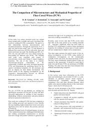
63 rd Annual Assembly & International Conference <strong>of</strong> the International Institute <strong>of</strong> Welding<br />
11-17 July 2010, Istanbul, Turkey<br />
<strong>Structural</strong> <strong>Integrity</strong> <strong>of</strong> <strong>Welded</strong> <strong>Structures</strong>:<br />
Process - Property – Performance (3P) Relationship<br />
Mustafa Koçak*<br />
Gedik Holding, Ankara Cad. No. 306 Seyhli - 34913 Pendik, Istanbul, Turkey<br />
mkocak@gedik.com.tr<br />
*Formerly at the GKSS Research Center, Geesthacht, Germany<br />
Houdremont Lecture<br />
Abstract<br />
In most engineering metallic structures, welded joints<br />
are <strong>of</strong>ten the locations for the crack initiation due to<br />
inherent metallurgical, geometrical defects as well as<br />
heterogeneity in mechanical properties and presence <strong>of</strong><br />
residual stresses. In order to maintain structural<br />
integrity <strong>of</strong> welded structures for whole service life <strong>of</strong><br />
the structure, relationship between welding process,<br />
properties (<strong>of</strong> base metal & weld joint) and<br />
performance <strong>of</strong> the structure (requirements &<br />
controlling factors <strong>of</strong> the service conditions) should be<br />
well-understood and established. The quality <strong>of</strong> the<br />
relationship between this 3P is crucial to obtain<br />
economic and safe design, fabrication and service life.<br />
Specific features <strong>of</strong> each welding and joining process<br />
should ideally be well understood by the designer for a<br />
selected material at the early stage <strong>of</strong> the design.<br />
Resulting microstructural & mechanical and<br />
geometrical properties should be obtained to have<br />
defined or intended structural performance under either<br />
specific environment or stresses.<br />
Nowadays, use <strong>of</strong> advanced welding processes with<br />
high performance steels and aluminium alloys together<br />
with well established and high quality welding<br />
consumables ensures safe and economic design,<br />
fabrication, inspection and service <strong>of</strong> the welded<br />
components and structures. Additionally, new<br />
developments in the fitness-for-service (FFS)<br />
procedures (e.g. BS 7910, R6 and FITNET FFS) and<br />
codes have significantly increased the accuracy <strong>of</strong> the<br />
structural integrity assessment <strong>of</strong> weld flaws.<br />
More and more engineering structures are built using<br />
multi-material design approach where numbers <strong>of</strong><br />
materials with significantly different mechanical<br />
properties are joined to create weight and cost-efficient<br />
structures. <strong>Structural</strong> safety evaluation <strong>of</strong> such materialmix<br />
structures require sound understanding and<br />
description <strong>of</strong> the welding process, interfacial & weld<br />
joint properties in conjunction with global behaviour <strong>of</strong><br />
the component under external loadings. The existing<br />
knowledge on the weld strength mis-match will<br />
significantly help to design innovative products and<br />
resolve complex deformation and fracture problems <strong>of</strong><br />
such emerging structures. Such structures are expected<br />
to perform under severe service conditions with<br />
minimum maintenance and safely.<br />
This Houdremont Lecture will, therefore, address to the<br />
engineering significance <strong>of</strong> the relationship between<br />
different stages <strong>of</strong> the “life <strong>of</strong> the welded structure”<br />
which I have been describing as 3P (Process-Property-<br />
Performance) <strong>of</strong> welded structures.<br />
Keywords: Welding process, weld property, structural<br />
performance, mis-match, weld metal, fracture, residual<br />
strength, fitness-for-service, FITNET, flaw assessment,<br />
line pipe, structural integrity, laser weld, aerospace, Alalloys.<br />
1. Introduction<br />
In recent years, significant new developments have<br />
taken place in the field <strong>of</strong> steel and weldability<br />
developments while new major projects and application<br />
fields require challenging properties from selected<br />
welding process and material combination. For<br />
example, possible new applications in arctic regions<br />
require steel structures and their weldments need to be<br />
designed and tested at -60°C to -70°C. Furthermore, the<br />
weldability in different positions may require to use<br />
different welding processes and welding consumables.<br />
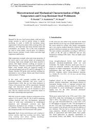
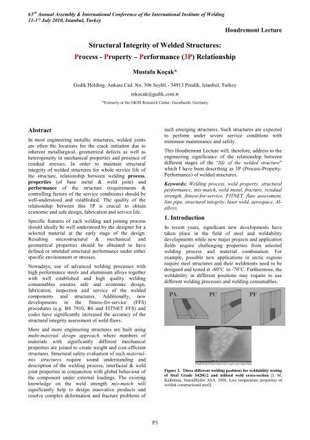
Figure 1. Three different welding positions for weldability testing<br />
<strong>of</strong> Steel Grade S420G2 and utilised weld cross-section [I. M.<br />
Kulbotten, StatoilHydro ASA, 2008, Low temperature properties <strong>of</strong><br />
welded constructional steel]<br />
P3
An example to this case could be seen in Figure 1 where<br />
same steel is welded at different positions using<br />
accordingly different welding process and consumables.<br />
PA refers to submerged arc welding (SAW), PC and PF<br />
are gas shielded flux cored arc welding with different<br />
heat inputs. It is most probable that these different<br />
welding positions (process variations) may lead to<br />
different joint properties and hence welded structure<br />
depending on the loading conditions may differ at<br />
different points.<br />
Therefore, it is essential to consider weld joint<br />
performance an integral part <strong>of</strong> the welding process and<br />
local properties (strength, notch etc.). For example,<br />
welding process parameters and selected consumables<br />
and base metal grade <strong>of</strong> line pipes are <strong>of</strong> major<br />
importance for the integrity <strong>of</strong> pipelines. The use <strong>of</strong><br />
fitness-for-service analysis at the design stage will<br />
enhance the accuracy <strong>of</strong> the decisions and hence will<br />
improve the productivity, safety <strong>of</strong> welded fabrication<br />
and integrity respectively.<br />
Weld joints usually exhibits heterogeneous properties<br />
across the joint. This particularly effects the<br />
performance <strong>of</strong> the structure. For this known reason<br />
weld strength mis-match has been a topic <strong>of</strong> research<br />
for same time. This paper gives special attention to this<br />
topic.<br />
2. Weld Strength Mis-match<br />
<strong>Structural</strong> weld joints, particularly bi-material<br />
(dissimilar) joints usually exhibit substantial mechanical<br />
heterogeneity with respect to elastic-plastic deformation<br />
and fracture properties. This heterogeneity is commonly<br />
called as „strength mis-match“ and expressed as yield<br />
strength mis-match;<br />
assisted cracking. In addition to this difficulty, there<br />
exists unintentional strength undermatching in high<br />
strength steel weldments. The weld joints may<br />
unknowingly be undermatched because the base metal<br />
has much higher yield strength than the SMYS<br />
(specified minimum yield strength). It should be noted<br />
that the undermatched welds can have a significant<br />
effect on the strength level, resistance to fracture and<br />
ductility <strong>of</strong> welded components. The undermatched<br />
welds are particularly sensitive if the welds operate<br />
under tension perpendicular to the weld seam. If the<br />
undermatched welds are loaded in a direction parallel to<br />
the weld length should present no problem, since the<br />
strain will not localise in the s<strong>of</strong>t weld seam.<br />
Particularly, since early nineties, numerous<br />
investigations have been conducted by the author [e.g<br />
1-6] to describe the effects <strong>of</strong> mis-matching on the<br />
fracture behaviour and toughness. Two special<br />
international conferences, Mis-match 93 [7] and Mismatch<br />
96 [8] have provided international forum and<br />
showed the significant progress had been made in<br />
this field. For example, currently, unified method to<br />
perform defect assessments in mis-matched welds<br />
exists. In this context, recently developed fitness-forservice<br />
procedure FITNET has provided clear<br />
guidline for assessment for such welds. However,<br />
significant amount <strong>of</strong> work is still needed,<br />
particularly in the areas <strong>of</strong> high strength steel<br />
weldments, treatment <strong>of</strong> HAZ s<strong>of</strong>tening and highly<br />
undermatched Al-alloy weldments while extensive<br />
validation cases <strong>of</strong> proposed approaches as well as<br />
treatment <strong>of</strong> material-mix (multi-material) structures<br />
are still missing.<br />
M=σ YW /σ YB<br />
Over-Match (OM)<br />
Under-Match (UM)<br />
Where σ YW is the weld metal yield strength and σ YB is<br />
the base metal yield strength. It is referred to as<br />
„overmatching if M>1 and called as „undermatching“ if<br />
M YS W<br />
Under-Matched<br />
B<br />
YS W<br />
YS B < YS W<br />
Figure 2. Schematic description <strong>of</strong> crack tip plasticity due to<br />
weld strength mis-match. LBW: Laser Beam Welding, FSW:<br />
Friction Stir Welding<br />
2H<br />
P4
63 rd Annual Assembly & International Conference <strong>of</strong> the International Institute <strong>of</strong> Welding<br />
11-17 July 2010, Istanbul, Turkey<br />
Houdremont Lecture<br />
Figure 2. Fracture path deviation into lower strength base metal<br />
<strong>of</strong> the centre cracked wide plate under tension. The weld metal<br />
exhibits strength overmatching.<br />
It is known that the essence <strong>of</strong> the strength mis-match<br />
lies on the crack tip plasticity development and effect <strong>of</strong><br />
the strength difference between weld and base metals<br />
on the deformation pattern at the crack tip and ahead <strong>of</strong><br />
the crack tip (uncracked ligament). Figure 2<br />
schematically showing the principal deformation<br />
patterns <strong>of</strong> the overmatching and undermatching cases<br />
with weld metal and HAZ cracked bodies as well as two<br />
major governing factors <strong>of</strong> M and 2H (weld width). The<br />
structural steels (up to some strength level) usually<br />
show overmatching while laser beam [9,11] and friction<br />
stir welded (FSW) high strength Al-alloys usually<br />
exhibit undermatching situations [4, 8]. Due to rapid<br />
cooling rate, LB welded ferritic steels and Ti-alloy<br />
show high hardness, and hence high degree <strong>of</strong><br />
overmatching.<br />
3. Properties <strong>of</strong> Weldments<br />
3.1 Tensile Properties<br />
<strong>Welded</strong> joints have heterogeneous mechanical<br />
properties and also exhibit highly heterogeneous<br />
microstructural variations in a local region. Adequate<br />
tensile and fracture toughness testing techniques<br />
consequently should incorporate such highly<br />
heterogeneous mechanical/microstructural features. The<br />
micro-flat-tensile (MFT) test technique [6, 9-11] is<br />
extremely useful to measure tensile properties <strong>of</strong> HAZ<br />
<strong>of</strong> multi-pass welds and very thin weld regions such as<br />
laser beam (LB) and electron beam (EB) welds. During<br />
the tensile testing <strong>of</strong> weld joint, transverse welded<br />
specimens usually fail away from the weld joint, if weld<br />
metal exhibits high strength overmatching, as shown in<br />
Figure.4. The results <strong>of</strong> such tests will inevitably<br />
provide base metal strength values but with reduced<br />
ductility, due to the presence <strong>of</strong> high strength zone<br />
within the gauge length. Advanced testing techniques<br />
with the use <strong>of</strong> image analysis system, it is possible to<br />
monitor the evolution <strong>of</strong> the plasticity across the<br />
specimen. Figure 5b is illustrating heterogeneous plastic<br />
strain localisation process for the undermatched FSW<br />
containing flat tensile specimen.<br />
Figure 4. Typical strength overmatched flat tensile specimens<br />
failed away from the weld zone.<br />
Micro-hardness variation across the FSW welded 2024<br />
Al-alloy 20 mm thick plate is showing Figure 5a the<br />
heterogeneous nature <strong>of</strong> the weld joint. During the<br />
testing <strong>of</strong> flat tensile specimen, one surface <strong>of</strong> the<br />
specimen was monitored to determine the strain<br />
localisation and hence ductile failure location with<br />
respect to heterogeneous cross-section <strong>of</strong> the joint. The<br />
images shown in Figure 4b are illustrating and verifying<br />
the indications <strong>of</strong> the micro-hardness results. The<br />
micro-hardness results have revealed that the centre part<br />
(nugget) <strong>of</strong> the joint is not the region with lowest<br />
strength, whereas HAZ (or TMHAZ) regions,<br />
particularly retreating side <strong>of</strong> the joint may have lowest<br />
strength and hence failure location. Indeed, during the<br />
tensile testing <strong>of</strong> the specimens <strong>of</strong> the EU project<br />
WAFS) <strong>of</strong> joint failed due to localisation <strong>of</strong> the plastic<br />
strain. The reason for this heterogeneity <strong>of</strong> the joint<br />
with respect to advancing and retreating sides <strong>of</strong> the<br />
FSW process is due to the temperature distribution<br />
during the process.<br />
a)<br />
P5
(b)<br />
Figure 5. Microhardness and tensile testing <strong>of</strong> strength<br />
undermatched Al-alloy 2024 FSW joint.<br />
a) Micro-hardness distribution at different depths <strong>of</strong> the FSW<br />
weld joint <strong>of</strong> 2024 Al-alloy<br />
b) ARAMIS images <strong>of</strong> the FSW joint during the tensile testing <strong>of</strong><br />
the joint. Images are showing at different stress levels<br />
corresponding strain distributions. [EU project WAFS]<br />
Figure 6 is showing the specimen extraction technique<br />
from EB welded material for determination <strong>of</strong> local<br />
tensile properties <strong>of</strong> the weld joint. The micro-flattensile<br />
specimens are 0.5 mm thick and 2.0 mm wide<br />
and most suitable for determination <strong>of</strong> mis-match level<br />
for HAZ regions <strong>of</strong> high strength steels where HAZ<br />
s<strong>of</strong>tening usually occur.<br />
Furthermore, this technique can be applied to determine<br />
the mechanical property gradient <strong>of</strong> the surface treated<br />
components which usually exhibit high degree <strong>of</strong><br />
strength mis-match. Figure 7 is illustrating the specimen<br />
extraction <strong>of</strong> laser surface cladded (hard layer) heavy<br />
section cast material (CuAl10Ni5Fe5) to determine the<br />
property gradient <strong>of</strong> the surface layer and substrate in<br />
thickness direction. This novel testing technique<br />
provides all needed tensile properties and their<br />
variations, associated with microhardness gradient, as<br />
shown in Figure 8.<br />
Figure 6. Extraction <strong>of</strong> micro flat tensile specimens from EB weld<br />
[10]<br />
Furthermore, this technique was applied to determine<br />
the tensile property variation <strong>of</strong> bi-material (2024 and<br />
6056) FSW welds <strong>of</strong> aerospace Al-alloys. Figure 9 is<br />
showing the yield and tensile strength in combination <strong>of</strong><br />
micro-hardness distributions across the FSW joint<br />
between two different Al-alloys.<br />
Strength mis-matching between weld metal and base<br />
metal is not always control the plastic deformation and<br />
hence fracture <strong>of</strong> the weld joint. The weld joints <strong>of</strong> the<br />
high strength steels may exhibit lower strength at the<br />
heat affected zones (HAZ s<strong>of</strong>tening) and this leads to<br />
strain localization under high external loading and<br />
hence show lower resistance to fracture at this location.<br />
An example for the HAZ s<strong>of</strong>tening is shown in Figure<br />
10<br />
Figure 7. Micro flat tensile specimens and standard round tensile<br />
specimen extracted from laser surface cladded thick section<br />
material<br />
Figure 8. Microhardness and yield strength (red solid symbols) variations obtained from laser claded (surface hard layer) cast material and<br />
principle illustration <strong>of</strong> the loading type <strong>of</strong> the micro-flat tensile specimens<br />
P6
63 rd Annual Assembly & International Conference <strong>of</strong> the International Institute <strong>of</strong> Welding<br />
11-17 July 2010, Istanbul, Turkey<br />
Houdremont Lecture<br />
Figure 9. Distribution <strong>of</strong> the micro-hardness, yield strength and tensile strength values across the friction stir welded dissimilar aerospace<br />
grade Al-alloys (2024 and 6056) butt-joint. The tensile properties are determined by testing <strong>of</strong> 0.5 mm thick micro-flat tensile specimens. [EU<br />
project WAFS]<br />
Figure 10. Distribution <strong>of</strong> yield and tensile strengths across the APIX80 pipeline steel (14.0 mm thick) weld (5 layer) showing HAZ s<strong>of</strong>tening.<br />
The values were obtained by testing <strong>of</strong> 0.5 mm thick micro-flat-tensile specimens (46 <strong>of</strong> them) extracted across the weld joint at the GKSS.<br />
P7
CTOD ( 5 ), mm<br />
.<br />
CTOD ( 5 ), mm<br />
In the absence <strong>of</strong> yield strength value (and full stressstrain<br />
curves) <strong>of</strong> narrow HAZ zone <strong>of</strong> high strength<br />
pipeline steel welds, a flaw assessment will use the base<br />
metal properties will then be potentially unsafe.<br />
Therefore, it is recommended to obtain full stress-strain<br />
curves <strong>of</strong> all regions <strong>of</strong> the weld joint if complex mismatch<br />
situation is <strong>of</strong> a concern, as demonstrated in<br />
Figure 10.<br />
3.2 Fracture Toughness Determination <strong>of</strong> Strength<br />
Mis-matched Welds<br />
Strength mis-match affects the constraint conditions<br />
near the crack tip, and hence effects <strong>of</strong> mis-match on<br />
the fracture toughness properties are to be expected.<br />
During the fracture toughness testing <strong>of</strong> very narrow<br />
weld metal zones (laser and electron beam welds, or<br />
HAZ regions) crack path deviation occurs towards<br />
lower strength regions as shown in Figure 11 below.<br />
Hence, the toughness value generated from such<br />
specimens will not represent “intrinsic fracture<br />
toughness” properties <strong>of</strong> the zone <strong>of</strong> interest. This<br />
situation is a consequence <strong>of</strong> the remote plasticity<br />
development in the neighbouring base metal, as<br />
illustrated in Figure 2 and hence obtained fracture<br />
toughness values are meaningless. It is obvious that<br />
plastically heterogeneous interfaces (both sides <strong>of</strong> the<br />
narrow fusion zone with much lower strength level than<br />
fusion zone) near to the crack tips experience high<br />
strain concentrations and this <strong>of</strong>ten leads to crack<br />
kinking out <strong>of</strong> the high strength but lower toughness<br />
region as illustrated in Figure 11.<br />
Figure 11. Two types <strong>of</strong> fracture path deviations into the lower<br />
strength base metal regions during the fracture toughness testing<br />
<strong>of</strong> highly overmatched laser beam welds <strong>of</strong> ferritic steels [12, Doc.<br />
X-F-078-98]<br />
homogeneous A specimen<br />
A<br />
R p0.2 =320Mpa<br />
homogeneous B specimen<br />
B<br />
R p0.2 =80Mpa<br />
B<br />
A<br />
R p0.2 =80Mpa<br />
8mm<br />
50mm<br />
overmatched specimen undermatched specimen<br />
a/W=0.5, Thickness=5mm<br />
0.8<br />
0.6<br />
UM: M=0.25<br />
a/W=0.5<br />
2H/(W-a)=0.32<br />
0.8<br />
0.6<br />
OM: M=4.0<br />
a/W=0.5<br />
2H/(W-a)=0.32<br />
0.4<br />
0.4<br />
0.2<br />
Homogeneous A<br />
Undermatching<br />
0.2<br />
Homogeneous B<br />
Overmatching<br />
0 0 1 2 3<br />
a, mm<br />
0 0 1 2 3<br />
a, mm<br />
Figure 12. CTOD 5-R-curves for highly over- and undermatched model weldments to demonstrate the geometry independency <strong>of</strong> the local<br />
CTOD measurement technique. Here, homogeneous means all weld metal SENB specimen [8]<br />
P8
63 rd Annual Assembly & International Conference <strong>of</strong> the International Institute <strong>of</strong> Welding<br />
11-17 July 2010, Istanbul, Turkey<br />
In this context, mis-match adjusted toughness<br />
evaluation methodology need to be used to<br />
compensate the mis-match induced constraint on<br />
toughness. Alternatively, fracture toughness can be<br />
obtained directly at the crack tip, using clip or noncontact<br />
displacement measurement/monitoring unit.<br />
One <strong>of</strong> the techniques in this field is the CTOD- 5<br />
technique (known as GKSS method) and this uses<br />
direct crack tip opening displacement measurements<br />
as toughness measurement. This toughness<br />
determination technique does not require any mismatch<br />
adjustments. This was demonstrated by using<br />
model weldments (EB welded bi-material SENB<br />
specimens) in Figure 12. The unique R-curves<br />
indicate the fact that local CTOD is not being<br />
influenced with the mechanical properties <strong>of</strong> the<br />
neighbouring zones.<br />
Houdremont Lecture<br />
The strength level <strong>of</strong> the weld metal influences the<br />
toughness values <strong>of</strong> the HAZ. This was demonstrated<br />
by testing <strong>of</strong> HAZ notched SENB specimens with<br />
shallow and deep notched specimens with using<br />
different wires which produced three distinct levels <strong>of</strong><br />
mis-match conditions for the same base metal. Figure<br />
13 is illustrating the effect <strong>of</strong> weld metal strength on the<br />
measured CTOD values for both lower (a/W=0.1) and<br />
higher constraint (a/W=0.5) specimens. Here, it should<br />
be noted that the local CTOD measurements were made<br />
with clip gauges, which enveloped both weld and<br />
HAZ+BM regions. Inevitably, obtained fracture<br />
toughness values exhibit “apparent HAZ toughness”<br />
values which do not represent intrinsic fracture<br />
toughness properties <strong>of</strong> the martensitic microstructure<br />
<strong>of</strong> the HAZ region.<br />
In order to investigate the interfacial fracture between<br />
two highly different metallic materials with respect to<br />
elastic and plastic properties, a bi-material model weld<br />
has been produced using ferritic and austenitic steels<br />
and diffusion bonding process. This project was studied<br />
together with EDF-France to improve understanding <strong>of</strong><br />
strength mis-match effect on the fracture toughness.<br />
Figure 14 is showing a round tensile specimen after<br />
testing <strong>of</strong> a such bi-material specimen where complete<br />
plastic strain accumulated within the weaker austenitic<br />
material part. Figure 15 is presenting the yield strength<br />
properties obtained from testing <strong>of</strong> micro flat tensile<br />
specimens across the interface. These results are also<br />
compared with the testing <strong>of</strong> standard round tensile<br />
specimens, as shown in Figure 15.<br />
Figure 13. Effect <strong>of</strong> weld metal strength on HAZ fracture<br />
toughness for two notch depths [1, 8]<br />
Figure 14. Post-test view <strong>of</strong> the bi-material round tensile specimen<br />
between ferritic and austenitic steels joined using diffusion<br />
bonding process.<br />
600<br />
R p0,2 (MPa)<br />
Ferrite<br />
500<br />
400<br />
Austenite<br />
300<br />
Micro Tensile - Part I<br />
Micro Tensile - Part II<br />
Micro Tensile - Average<br />
Round Tensile<br />
200<br />
100<br />
0<br />
D istance to the Interface (m m )<br />
-8 -7 -6 -5 -4 -3 -2 -1 0 1 2 3 4 5 6 7 8<br />
Figure 15. Yield strength values <strong>of</strong> bi-material joint between austenitic and ferritic steel. The results are generated with the testing <strong>of</strong> 0.5 mm<br />
thick micro-flat tensile specimens. Bulk material properties are compared with round specimens extracted away from the interface.<br />
P9
Fracture toughness properties <strong>of</strong> such bi-material<br />
interfaces were determined using SENB specimens<br />
notched at various locations at the vicinity <strong>of</strong> the bimaterial<br />
interface. The initial notch was located at the<br />
interface (I), ferrite (F) and austenite (A) materials with<br />
constant distance to the interface. Figure 16 is showing<br />
the load vs. CMOD curves obtained from various<br />
specimen types, which are schematically shown with<br />
obtained respective curve. The specimen with<br />
interfacial crack shows immediate effect <strong>of</strong> higher<br />
strength ferrite material by having higher load carrying<br />
capacity. However, most striking effect <strong>of</strong> lower<br />
strength material on the fracture toughness <strong>of</strong> ferrite<br />
material is to prevention (orange colour curve) <strong>of</strong><br />
unstable fracture phenomena which is the intrinsic<br />
property <strong>of</strong> the ferrite (red curve). It appears that the<br />
critical stress state needed for a brittle or unstable crack<br />
initiation is not reached by relaxation <strong>of</strong> the crack tip<br />
stress by remote plasticity within the austenite.<br />
Accompanying numerical investigations <strong>of</strong> this bimaterial<br />
system was conducted in France has also<br />
materialised these results. These test results have shown<br />
significant effect <strong>of</strong> the material properties <strong>of</strong><br />
neighbouring zone adjacent to the interface.<br />
Figure 17. Macro section <strong>of</strong> the sub-interface crack tip (located<br />
into the ferritic-F- steel side <strong>of</strong> the interface) and strong crack<br />
path deviation towards lower strength (but toughnes) austenitic-<br />
A- material. The figure is also schematically showing the<br />
development <strong>of</strong> heterogeneous plastic zone at the interface region.<br />
Unstable deformation behaviour <strong>of</strong> all-ferrite specimen<br />
(shown in red colour curve) becomes stable once<br />
specimen contains s<strong>of</strong>t (lower strength) austenite<br />
material, as orange colour curve demonstrates.<br />
Figure 16. Load vs. CMOD curves <strong>of</strong> SENB specimens containing bi-material interface. Notch locations were varied, where blue colour SENB<br />
specimen (HoBP-F-7) representing all-ferrite homogeneous specimen while white coloured specimen (HoBP-A-4) refers to all austenite<br />
material.<br />
P10
63 rd Annual Assembly & International Conference <strong>of</strong> the International Institute <strong>of</strong> Welding<br />
11-17 July 2010, Istanbul, Turkey<br />
An extensive development <strong>of</strong> plasticity at the lower<br />
strength (A) side <strong>of</strong> the bi-material specimen has<br />
inevitably occurred and crack growth took place taking<br />
into account <strong>of</strong> least resistance path <strong>of</strong> the interface<br />
region. Apparently, banded microstructural feature <strong>of</strong><br />
the ferritic steel has provided easy crack path to develop<br />
a ductile crack towards lower strength material. These<br />
tests confirm that cracks tend to go into the lower<br />
strength material or zone due to localisation <strong>of</strong> the<br />
plastic deformation. Fracture toughness values obtained<br />
from such systems will not represent “intrinsic”<br />
material properties <strong>of</strong> the material where crack tip<br />
originally placed.<br />
Houdremont Lecture<br />
Figure 19. Effect <strong>of</strong> specimen thickness (B) on fracture toughness<br />
<strong>of</strong> 38 mm thick steel welded EBW process [Unpublished results<br />
from EU Project ASPOW]<br />
Figure 18. CTOD results for undermatched, matched and<br />
overmatched welds <strong>of</strong> X80 steel [58].<br />
Further implications <strong>of</strong> such investigations on model<br />
welds with respect to strength-undermatched systems<br />
are clearly visible. Weld joints <strong>of</strong> high strength Al-alloy<br />
welds and HAZ s<strong>of</strong>tened regions <strong>of</strong> pipeline steel welds<br />
will be potential failure locations due to the localization<br />
<strong>of</strong> plastic deformation.<br />
The work <strong>of</strong> M. Ohata and M. Toyoda [38] was<br />
conducted on the X-80 pipeline steel weldments using<br />
three different wires and analysing the fracture<br />
performance <strong>of</strong> these welds with surface cracked wide<br />
plates showed the effect <strong>of</strong> mis-match on the fracture<br />
performance <strong>of</strong> these welds. Figure 14 is showing the<br />
fracture toughness values for different strength mismatch<br />
conditions. Fracture toughness <strong>of</strong> the EB welds<br />
(highly overmatched) on 38 mm thick steel was<br />
determined using deep notched SENB specimen to<br />
investigate the effect <strong>of</strong> specimen thickness (B) on the<br />
fracture toughness <strong>of</strong> the EB weld fusion zone (FZ).<br />
In addition to the SENB specimens with full plate<br />
thickness <strong>of</strong> 38 mm, the specimens with 19mm, 9.5 mm<br />
and 4.75 mm thickness were prepared and tested with<br />
identical a/W ratio <strong>of</strong> 0.5. The results are presented in<br />
Figure 15. The results are showing clearly the effect <strong>of</strong><br />
the specimen thickness (B) for a given weld width (2H)<br />
and uncracked ligament (W-a) on the so-called<br />
“apparent fracture toughness”. Although, crack tip was<br />
located at the identical microstructure, reduction <strong>of</strong><br />
specimen thickness caused an increase <strong>of</strong> apparent<br />
toughness (and <strong>of</strong> scatter) <strong>of</strong> highly overmatched EB<br />
weld fusion zone. Reduction <strong>of</strong> the constraint (a<br />
decrease <strong>of</strong> B/2H or B/(W-a) <strong>of</strong> the overmatched SENB<br />
specimen, therefore, shows an increase <strong>of</strong> “apparent<br />
toughness’ which does not represent an “intrinsic<br />
fracture toughness” <strong>of</strong> the EB weld zone.<br />
3.3 Weld Strength Mis-matched <strong>Structures</strong> under<br />
Cyclic Loading<br />
Weld strength mis-match principally plays a significant<br />
role under elastic-plastic loading conditions where large<br />
plasticity at the crack tip interacts with different<br />
materials/regions with different mechanical properties.<br />
Once interaction occurs and neighbouring material<br />
influences the evolution <strong>of</strong> the crack tip stress/strain<br />
state, under external loading, one should expect an<br />
influence <strong>of</strong> mis-match on the deformation and/or<br />
failure behaviour <strong>of</strong> the welded component. Numerous<br />
investigations have been conducted to characterise the<br />
constrained plasticity and interface fracture toughness<br />
issues both under small and large-scale yielding<br />
conditions and some <strong>of</strong> these are reported in the<br />
proceedings <strong>of</strong> the Mis-match 93 and Mis-match 96<br />
International conferences.<br />
P11
Figure 20. Fatigue crack growth at the fusion line region <strong>of</strong> the<br />
laser welded Al-alloy which exhibits strong undermatching [24]<br />
Recent studies at the GKSS have focussed on the<br />
strength undermatched structures operating both under<br />
cyclic (constant and variable amplitude) and static<br />
loadings due to the increasingly use <strong>of</strong> higher strength<br />
materials. The evaluation <strong>of</strong> fatigue crack in laser beam<br />
and friction stir welded Al-alloy weldments exhibiting<br />
highly strength undermatching conditions have been<br />
investigated. Figure 16 is showing the fatigue crack<br />
growing at the interface (fusion line) between highly<br />
undermatched weld zone and base metal.<br />
Figure 17 a illustrates the fatigue testing <strong>of</strong> fillet weld<br />
(laser welded skin-stringer joints <strong>of</strong> airframes) where<br />
horizontal plate (i.e skin) was subjected to the cyclic<br />
loading, as arrows are indicating. When this welded<br />
configuration (with highly strength undermatched joint)<br />
is subjected to fatigue loading, a fatigue crack easily<br />
initiates at the weld toe and advances along the fusion<br />
line, almost parallel to the loading axis and turns into<br />
sheet thickness direction once reaches to the bottom <strong>of</strong><br />
the fillet weld where angle <strong>of</strong> the weld changes. Figure<br />
17b reveals further effect <strong>of</strong> interface mis-match on the<br />
growing fatigue crack. It appears that as the plastic zone<br />
ahead <strong>of</strong> the fatigue crack in the s<strong>of</strong>t weld zone touches<br />
the interface (very thin layer <strong>of</strong> precipitation free s<strong>of</strong>t<br />
zone) with adjacent base metal with higher strength, the<br />
crack kinks to the interface which is not perpendicular<br />
to the loading axis. Continued cyclic loading causes<br />
micro-bifurcation within the s<strong>of</strong>t interface region before<br />
penetrating back into the base metal region. These<br />
examples are clearly showing how strength<br />
heterogeneity both large scale and micro-level operate<br />
to control the advance <strong>of</strong> the damage and failure <strong>of</strong> the<br />
component. This kind <strong>of</strong> information can be utilised to<br />
design effective crack arresters/barriers to achieve<br />
fatigue resistant heterogeneous or bi-material systems.<br />
(a)<br />
(b)<br />
Figure 21. Fatigue crack growth features along the interface <strong>of</strong><br />
the laser welded fillet welds <strong>of</strong> 6xxx series <strong>of</strong> aerospace Al-alloy, a)<br />
crack initiates at the weld toe and propagates along the fusion line<br />
towards bottom <strong>of</strong> the fillet weld, b) micrograph <strong>of</strong> a crack<br />
initiated and advanced within the s<strong>of</strong>t weld, but once reaches to<br />
the interface turns into the much s<strong>of</strong>ter interface layer.<br />
Figure 22. Macro-section <strong>of</strong> the laser spot welded steel Sheets and<br />
strain distribution at the vicinity <strong>of</strong> the strength overmatched<br />
weld vicinity during the coach peel test [36]<br />
Recently developed advanced high strength steels<br />
(AHSS) are used in car body using resistance spot<br />
welding. This welding technology is being<br />
challenged with developments in laser beam welding.<br />
Laser spot welding for such applications create<br />
highly overmatched spot welds. Figure 18 is showing<br />
a cross section and FE simulation <strong>of</strong> such joints<br />
under peel testing conditions. Strength overmatch <strong>of</strong><br />
weld and smaller weld volume in the lower sheet<br />
determines the failure location in the lower sheet.<br />
P12
63 rd Annual Assembly & International Conference <strong>of</strong> the International Institute <strong>of</strong> Welding<br />
11-17 July 2010, Istanbul, Turkey<br />
Houdremont Lecture<br />
4. Performance <strong>of</strong> Welds<br />
4.1 <strong>Structural</strong> <strong>Integrity</strong> Assessment <strong>of</strong> Weld<br />
Strength Mis-matched <strong>Structures</strong><br />
<strong>Structural</strong> integrity assessment <strong>of</strong> components<br />
containing flaw can be conducted to determine one <strong>of</strong><br />
the following objectives [27];<br />
- to select suitable material for a given tolearable defect<br />
size, as specified in the design;<br />
- to find the defect tolerance <strong>of</strong> a welded structure;<br />
- to find if a known defect is acceptable; to determine<br />
or extend the life <strong>of</strong> a structure;<br />
- to determine cause <strong>of</strong> failure.<br />
Analysis<br />
Options<br />
Type <strong>of</strong> tensile<br />
data required<br />
Type <strong>of</strong> fracture toughness<br />
data required<br />
Other information<br />
0<br />
Basic<br />
YS or SMYS<br />
only<br />
None; Charpy energy only<br />
Relies on correlations; applicable to<br />
ferritic steels only<br />
1<br />
Standard<br />
YS and UTS<br />
Single-point fracture<br />
toughness data or tearing<br />
resistance curves<br />
Based on tensile properties <strong>of</strong> the weaker<br />
material (typically the PM) and the<br />
fracture toughness <strong>of</strong> the material in<br />
which the flaw is located<br />
2<br />
Mismatch<br />
YS and UTS <strong>of</strong><br />
PM and WM<br />
Single-point fracture<br />
toughness data or tearing<br />
resistance curves<br />
Takes account <strong>of</strong> strength mismatch;<br />
typically worth applying only if M 1.1<br />
or M
Assessment for Postulated or Real Flaw<br />
Material & Weld related<br />
input parameters:<br />
Component related<br />
input parameters:<br />
• Tensile data, Fracture •Flaw size, Stress analysis,<br />
toughness, W Mis-match ratio,...<br />
K- and Yield load solutions,...<br />
a<br />
FITNET FFS ANALYSIS for WELDS<br />
Mis-match ratio<br />
M=YS WM /YS BM<br />
Prediction <strong>of</strong> critical condition<br />
• Flaw Size<br />
• Stress Level<br />
• Material Property<br />
Figure 24. Flow chart <strong>of</strong> the Fracture Module <strong>of</strong> the FITNET FFS Procedure for assessment <strong>of</strong> the weld flaw.<br />
Defects in welded structures <strong>of</strong>ten occur within or<br />
near welds across which tensile properties<br />
significantly vary. As described in previous sections,<br />
this strength mis-match in tensile properties can<br />
affect the plastic deformation pattern <strong>of</strong> the defective<br />
component, and thus the crack driving force such as<br />
CTOD or J integral. Until research work was<br />
conducted within European project SINTAP [18, 37],<br />
existing defect assessment methods were restricted to<br />
the homogeneous structures. In principle, the<br />
methods for homogenous structures can be applied to<br />
welded structures, if the tensile properties <strong>of</strong> the<br />
weakest material are used; for instance, for<br />
overmatched welds (M>1), those <strong>of</strong> the base metal.<br />
However, such a simplified approach can lead to an<br />
unduly conservative result, and thus a FFS<br />
methodology specific to strength mismatched<br />
structures was needed to reduce excessive<br />
conservatism. For this very reason, the SINTAP<br />
Procedure [14, 18, 25, 37] introduced a novel flaw<br />
assessment route for strength mis-match welds.<br />
FITNET FFS Procedure [34, 35] takes over these<br />
routes (Options 2 and 3), Figure 18, for treatment <strong>of</strong><br />
conventional multi-pass and advanced (laser and<br />
friction stir) welded structures [25, 31, 32]. The latter<br />
one particularly exhibits significant (up to 50%)<br />
strength undermatching in structural welds used in<br />
aluminium structures <strong>of</strong> automobile, marine and<br />
aerospace. Figure 20 illustrates the principle <strong>of</strong> the<br />
FITNET FFS procedure for weldments.<br />
4.2 Mis-match Limit Load<br />
The limit load <strong>of</strong> the welded structure is the most<br />
crucial parameter for the assessment <strong>of</strong> the strength<br />
mis-matched welded structures. The limit load <strong>of</strong><br />
mis-matched structures differs from those <strong>of</strong><br />
homogeneous all base metal or all weld metal<br />
structures or considerations. It lies between these two<br />
limits and controls the evolution <strong>of</strong> plastic<br />
deformation <strong>of</strong> the cracked body and hence <strong>of</strong> the<br />
crack driving force. In classical solid mechanics the<br />
limit load is defined as the maximum load a<br />
component <strong>of</strong> elastic-ideally plastic material is able<br />
to withstand, above this limit ligament yielding<br />
becomes unlimited. In contrast to this definition, real<br />
materials strain harden with the consequence that the<br />
applied load may increase beyond the value given by<br />
the non-hardening limit load. Sometimes strain<br />
hardening is roughly taken into account by replacing<br />
the yield strength <strong>of</strong> the material by an equivalent<br />
yield strength (flow strength) in the limit load<br />
equation. In the fitness-for-service (FFS) analysis<br />
procedure FITNET, numbers <strong>of</strong> limit load solutions,<br />
including newly developed [e.g 13, 15,] are given<br />
in Annex B (Vol II) [35]. The results and recent<br />
developments <strong>of</strong> SINTAP, BS7910, R6 sources are<br />
used to generate this Annex.<br />
Extensive validation works have been conducted<br />
during the development <strong>of</strong> the FITNET FFS<br />
Procedure. Some <strong>of</strong> these investigations can be found<br />
in [21-33]. Furthermore, series <strong>of</strong> collected case<br />
P14
63 rd Annual Assembly & International Conference <strong>of</strong> the International Institute <strong>of</strong> Welding<br />
11-17 July 2010, Istanbul, Turkey<br />
studies used both during validation and training <strong>of</strong><br />
young engineers (Hand outs and lecture notes for<br />
FITNET Training Seminars) and this volume will<br />
also be released soon.<br />
4.3 Weld Strength Mis-match in Steel Pipelines<br />
Extensive investigations have been conducted during<br />
last decades to develop steels, welding technologies<br />
and improvements <strong>of</strong> design and flaw assessment<br />
guidelines for oil and gas linepipes. These<br />
developments have played a significant role for safe<br />
and economic transportation <strong>of</strong> natural gas and oil as<br />
well as their field developments. Offshore pipelines<br />
in deep water and long distance gas transporation<br />
produced challenges to develop high strength and<br />
high toughness steels to reduce cost. Up to X120<br />
steel grades have been developed and weldability,<br />
strength mis-match and crack arrest issues were<br />
intensely investigated. The higher strength and<br />
toughness could be reached by the TMCP while<br />
maintaining the good weldability (keeping Ceq at a<br />
suitable level).<br />
It is known that for high strength steels, the potential<br />
for only slightly overmatching or even matching is<br />
more likely to occur than the lower strength steels.<br />
Therefore, whenever the seam weld or girth weld <strong>of</strong><br />
the pipe may influence the limit state <strong>of</strong> the pipe,<br />
weld strength overmatching should be maintained to<br />
start with. This situation appears to be more difficult<br />
to fulfil for X120 (827 MPa) steel pipes and strength<br />
undermatching most likely to occur to satisfy the<br />
toughness and ductility requirements. The steel<br />
producers <strong>of</strong> X120 grade utilizes a different<br />
microstructural system which is different than<br />
typically used in X80 (quench and temper<br />
microstructure). This in turn may affect the crack<br />
arrest (propagating ductile fracture) behaviour <strong>of</strong><br />
such steels and welds.<br />
The strength <strong>of</strong> linepipe is generally increasing to<br />
reduce the cost and hence the linepipe steel X100 has<br />
been developed by many steel manufacturers using<br />
basically steel chemistries <strong>of</strong> low C- high Mb, Mo,<br />
Nb (V) microalloyed system with Cu, Ni and Cr<br />
using TMCP technology. However, these steels show<br />
significant HAZ s<strong>of</strong>tening and insufficient<br />
overmatching weld metal. During the last decades,<br />
the Y/T (yield to tensile) ratio <strong>of</strong> pipeline steels has<br />
increased from about 0.80 to 0.9 and above. Today,<br />
pipeline steel standards (e.g API 5L and DIN 17172)<br />
specify a maximum Y/T ratio <strong>of</strong> 0.93 to ensure<br />
sufficient ductility.<br />
It is <strong>of</strong>ten reported that cross-weld tensile properties<br />
determined by the properties <strong>of</strong> HAZ and weld metal<br />
fractures. Even most <strong>of</strong> the burst tests reported to be<br />
failed in the weld joints <strong>of</strong> high strength steel pipes.<br />
It is obvious that designers <strong>of</strong> pipelines (especially<br />
for strain based applications) are unlikely select weld<br />
metal that is undermatched compared to the base<br />
metal. However, lower strength regions in girth weld<br />
applications can still occur, even when the weld<br />
Houdremont Lecture<br />
metal is overmatched. For example, root pass is <strong>of</strong>ten<br />
welded manually with an undermatched consumable<br />
to reduce the risk <strong>of</strong> hydrogen cracking and promote<br />
better tie-ins. Further, HAZ regions, can exhibit<br />
lower strength then either the weld metal and base<br />
material, as shown in Figure 21.<br />
These results have been presented during recent<br />
pipeline conferences (e.g. Pipe Dreamer’s<br />
Conference, 7-8 Nov. 2002, Yokohama, Japan and<br />
4th Pipeline Technology conference, 9-13 May 2004,<br />
Ostend, Belgium).<br />
It has been also shown [19] that internal pressure <strong>of</strong><br />
pipelines can concentrate the strain into low-strength<br />
HAZ <strong>of</strong> girth welds and an elevation <strong>of</strong> strain in the<br />
HAZ may not be proportionally increase with the<br />
remote strain to failure. This and similar other<br />
investigations [e.g. 16, 20 see also proceedings <strong>of</strong><br />
Pipe dreamers conference and Pipeline technology<br />
conference volumes] have revealed that the structural<br />
significance <strong>of</strong> local strain elevation topic needs<br />
further investigations.<br />
Figure 25. Hardness distribution across the weld joint <strong>of</strong> X100<br />
steel, showing HAZ s<strong>of</strong>tening (undermatching) while weld metal<br />
exhibit overmatching [16].<br />
Furthermore, high longitudinal strain is one <strong>of</strong> the most<br />
critical loading conditions experienced by pipeline girth<br />
welds. Such high longitudinal strain in onshore<br />
pipelines is <strong>of</strong>ten associated with soil movements<br />
(seismic activity, slope instability etc.). On the<br />
otherhand <strong>of</strong>or <strong>of</strong>fshore pipelines, high longitudinal<br />
strains occur during the pipe laying operation (reeling)<br />
and it can be as high as 2-3%. Presently, DNV Offshore<br />
Standard F101 provides substantial guideline for defect<br />
acceptance criteria for under longitidunal strain<br />
condition and this guideline suggest to use BS7910<br />
(Level 3) type <strong>of</strong> analysis (which is also stress based), if<br />
the accumulated strain is higher than 0.3%. Recently<br />
developed FITNET Fitness for Service Procedure does<br />
not provide a strain based analysis and it is planned to<br />
develop a section addressing to this topic including<br />
P15
analysis <strong>of</strong> higher grade steel pipes (higher Y/T ratio<br />
materials) and welds (beyond X80) and crack arrest<br />
issues <strong>of</strong> these steel linepipes.<br />
One <strong>of</strong> the open issues that need to be dealt with is the<br />
generation <strong>of</strong> low-constraint fracture toughness values<br />
<strong>of</strong> the welds and HAZ regions using SENT specimens.<br />
Currently, no solution is available to conduct mis-match<br />
corrected toughness (CTOD and J) testing procedure for<br />
such specimens. Particularly, testing <strong>of</strong> welds with HAZ<br />
s<strong>of</strong>tening (together with weld metal mis-match ratio)<br />
and inclusion <strong>of</strong> its effect on fracture toughness and<br />
crack driving force estimation (beyond the elastic strain<br />
range) is a complex issue and need further research.<br />
4.4 Weld Strength Undermatching: <strong>Welded</strong> Thinwalled<br />
Al-alloy Aerospace <strong>Structures</strong><br />
Thin-walled components such as used in aerospace and<br />
ship structures are designed to satisfy the damage<br />
tolerance requirements <strong>of</strong> fatigue and residual strength.<br />
The residual strength <strong>of</strong> a homogeneous structure is<br />
basically a function <strong>of</strong> material properties (strength,<br />
toughness etc.), flaw and component geometries as well<br />
as the applied stress. The residual strength assessment<br />
route, therefore, is well established and successfully<br />
used for the riveted (differential) structures in the last<br />
decades. However, assessment <strong>of</strong> welded (integral)<br />
structures requires detailed information on the local<br />
weld joint (fusion or nugget area and heat affected<br />
zone) properties and weld geometry. This information is<br />
<strong>of</strong> particular importance if the weld joint exhibits<br />
mechanical heterogeneity (strength mismatch). Joining<br />
<strong>of</strong> aluminium alloys by friction stir (FSW) or laser<br />
beam welding (LBW) usually produces a weld joint<br />
area having significantly lower strength<br />
(undermatching) than the base metal and this needs to<br />
be taken into account during the structural integrity<br />
assessment. In such welded structures, a lower strength<br />
weld zone may lead to a plastic strain concentration in<br />
the weld joint if it is loaded beyond the yield stress <strong>of</strong><br />
the weld material and, hence, to the development <strong>of</strong><br />
higher constraint within the weld region due to this<br />
heterogeneous deformation behaviour. Therefore, this<br />
strength mismatch induced complexity needs to be<br />
considered when residual strength analysis is conducted<br />
for such structures. Most <strong>of</strong> the published validation<br />
cases <strong>of</strong> the FITNET FFS Procedure deal with strength<br />
overmatched welded thick-walled components where<br />
such welds are common for steel structures. There was<br />
a need to generate new experimental data on highly<br />
undermatched thin-walled structures to provide<br />
validation cases for the FITNET FFS Procedure [35]<br />
where welded structures with strength mismatch can be<br />
assessed. Recently, some validation cases [18, 22-25].<br />
were successfully undertaken with particular interest to<br />
structures welded with advanced joining techniques and<br />
containing strength mismatched welds. The recent<br />
studies, therefore, focussed to the application and<br />
validation <strong>of</strong> the FITNET FFS Procedure on thin-walled<br />
Al-alloy airframe structures where base metal and LBW<br />
and FSW welded large panel tests provide experimental<br />
data [20]. These investigations need to be extended to<br />
the improvement <strong>of</strong> damage tolerance performance <strong>of</strong><br />
weld strength mis-matched components using so-called<br />
“local engineering” methods. These methods include<br />
modifications <strong>of</strong> stress state around the weld area by<br />
tailoring <strong>of</strong> the joint design, welding process and<br />
surface treatments.<br />
The use <strong>of</strong> adequate and precise input parameters<br />
(based on the experimental observations <strong>of</strong> the damage<br />
process in the undermatched weld area) is particularly<br />
essential to describe and predict the critical condition in<br />
such structures. The selection <strong>of</strong> strength and toughness<br />
values to be used in the assessment has significant<br />
implications on the outcome <strong>of</strong> the analysis and require<br />
new considerations to avoid excessive conservatism <strong>of</strong><br />
the predictions.<br />
The treatment <strong>of</strong> the significantly strength<br />
undermatched thin-walled laser welded Al-alloys both<br />
in butt-joint and stiffened panel configurations have<br />
been investigated and Refs. [18-21] report the results. A<br />
large number <strong>of</strong> mis-match limit load solutions in the<br />
existing SINTAP procedure is being reviewed and<br />
extended (for example covering clad (bi-material)<br />
structures) and given in Annex B <strong>of</strong> the second volume<br />
<strong>of</strong> FITNET FFS.<br />
As an example, two panel results <strong>of</strong> the strength<br />
undermatched laser welded aerospace Al-alloys<br />
programme [18, 22-24] was selected to demonstrate the<br />
application <strong>of</strong> FITNET FFS Mis-match Option. Figures<br />
26 and 27 are showing both experimental results <strong>of</strong> the<br />
panels and comparison with the FITNET predictions<br />
where three different m-values (intends to quantify the<br />
constraint at the crack tip) are used to determine the<br />
sensitivity <strong>of</strong> the analysis to the m-values (where<br />
δ 5 =K J 2 /m R p0.2 E).<br />
The mis-match yield load and load carrying capacity<br />
level <strong>of</strong> the cracked panels provide information on the<br />
stress state in the uncracked ligament ahead <strong>of</strong> the<br />
crack. The failure <strong>of</strong> the undermatched panel occurred<br />
above the yield load indicating an elastic-plastic regime<br />
but it was far below the tensile strength (approx. 350<br />
kN) <strong>of</strong> the laser welded joint giving rise to failure<br />
caused by a critical crack tip condition (mis-matched<br />
induced) and not by plastic collapse.<br />
The variation <strong>of</strong> parameter m shows that for larger m,<br />
the predicted curve becomes stiffer, reaching its<br />
maximum at smaller CTOD values, Figure 27. For<br />
m=2.0, the FITNET prediction is in good agreement<br />
with the experimental failure load as well as the<br />
deformation behaviour. This result shows that strength<br />
undermatching indeed increases the crack tip constraint<br />
to the level <strong>of</strong> plane strain, although 2.0 mm thick panel<br />
under tension, if it was homogeneous, should operate<br />
under plane-stress condition.<br />
Furthermore, FITNET analysis carried out in [24] for a<br />
much more complex case <strong>of</strong> reinforced thin panels<br />
containing laser welded multiple stringers. In this case,<br />
P16
63 rd Annual Assembly & International Conference <strong>of</strong> the International Institute <strong>of</strong> Welding<br />
11-17 July 2010, Istanbul, Turkey<br />
Al-alloy panels with three longitudinally laser welded<br />
stringers are tested (test 1 and test 2) and load vs.<br />
CTOD curves are predicted with FITNET FFS<br />
Procedure. Two analysis Options are used, that the<br />
predictions are in good agreement with experimental<br />
results while predictions are remaining at the<br />
conservative side, Figure 27.<br />
The Fracture Module provides a hierarchical assessment<br />
structure (Options) based on the quality <strong>of</strong> available<br />
input data. Using a higher assessment option ensures a<br />
decrease in conservatism due to an increase <strong>of</strong> data<br />
quality. Refining the stress analysis <strong>of</strong> the component<br />
and/or improving the sizing <strong>of</strong> the flaw under<br />
consideration can also achieve a decrease in<br />
conservatism. The use <strong>of</strong> Option 3, as shown in Figure<br />
28, proves that the higher analysis Option decreases the<br />
conservatism in predictions.<br />
Houdremont Lecture<br />
Figure 27. Comparison between FITNET FFS Fracture Module<br />
Option 2 (mis-match) predictions and experimentally obtained<br />
load vs. CTOD curves <strong>of</strong> the thin-walled panels described in Fig.<br />
5. The R-curve was used in the analysis was obtained from small<br />
C(T)50 type fracture toughness specimens [24]<br />
4.5 Current status <strong>of</strong> the FITNET procedure<br />
Figure 26. Load vs. CTOD curve <strong>of</strong> the center cracked 760 mm<br />
wide plate. The panel was 2.0 mm thick (weld joint area 2.6mm)<br />
aerospace grade Al-alloy 6013 and contained highly<br />
undermatched 3.0 mm wide laser weld. Furthermore, figure<br />
contains images <strong>of</strong> the plasticity development at the crack tip and<br />
within the strength undermatched weld. FITNET FFS Procedure<br />
was applied to predict the failure load (point 5) <strong>of</strong> this thin-walled<br />
and highly mis-matched weld panel under tension [24]<br />
The FITNET FFS procedure is currently available,<br />
Figure 9 to interested parties in the form <strong>of</strong> a final<br />
document, Revision MK8 [34, 35]. The ultimate aim<br />
remains to publish the procedure (Volumes I and II) as<br />
a CEN document, via a CEN workshop agreement<br />
(CWA 22). It is likely that the volume containing<br />
validation, case studies and tutorials will remain the<br />
intellectual property <strong>of</strong> the FITNET consortium, and<br />
will be published separately by them. In the meantime,<br />
plans are underway to adopt relevant parts <strong>of</strong> FITNET<br />
into a future edition <strong>of</strong> the BS 7910, the UK national<br />
procedure.<br />
Figure 28. FITNET FFS predictions (Option 1 and Option 3) <strong>of</strong> a<br />
residual strength <strong>of</strong> laser welded 3-stringer panel with large<br />
central crack (broken central stiffener) [24].<br />
P17
5. Final Remarks<br />
Extensive international efforts have been made to<br />
design and assess the primary welded engineering<br />
structures for safer operation provided framework for<br />
significant progress and numbers <strong>of</strong> sucess stories to<br />
develop. For this process-property-performance<br />
relationships have been established for various systems.<br />
Research should continue to develop technology and<br />
knowledge applicable to all industrial sectors operating<br />
load-bearing structures, which require safety to be<br />
properly inbuilt in the design and fabrication processes<br />
as well as structural health monitoring, quality<br />
inspections and maintenance to ensure the structural<br />
safety throughout their lifetime.<br />
On the other hand, engineering structures will<br />
increasingly be fabricated using “multi-material design”<br />
principles, which will use different materials with<br />
different mechanical properties to increase the structural<br />
efficiency and for cost and weight reduction purposes.<br />
This will expand the heterogeneous nature <strong>of</strong> the<br />
components with numbers <strong>of</strong> dissimilar joint interfaces.<br />
Treatment <strong>of</strong> defects and cracks in such components<br />
will require new approaches and methodologies. Long -<br />
term research is therefore, needed to develop and<br />
establish the structural safety principles <strong>of</strong> the hybrid<br />
components increasingly used in various manufacturing<br />
industries. Multi-material design principles should<br />
make use <strong>of</strong> the existing knowledge on the strength mismatch.<br />
6. Acknowledgements<br />
The author was worked about 25 years at the GKSS<br />
Research Center, Geesthacht, Germany. Hence, the<br />
materials used in this paper have been generated during<br />
these years at the GKSS. Author wish to acknowledge<br />
the valuable contribution <strong>of</strong> the former colleagues.<br />
References<br />
[1] M. Koçak, M. Es-souni, L. Chen and K.-H. Schwalbe,<br />
“Microstructure and weld metal matching effects on HAZ<br />
toughness”, Proc. <strong>of</strong> the 8th Int. Conf. OMAE-ASME, The<br />
Hauge, Netherlands, March 19-23, 1989, pp. 623-633.<br />
[2] M. Koçak, J. Knaack and K.-H. Schwalbe, “Fracture behaviour<br />
<strong>of</strong> undermatched weld joint”, Proc. <strong>of</strong> the 9th Int. Conf. OMAE-<br />
ASME, Houston, Texas, USA, Feb. 18-23, 1990, Vol. III-Part<br />
B, pp. 453-459.<br />
[3] E. Tschegg, HOK Kirchner and M. Koçak, “Cracks at the<br />
Ferrite-Austenite Interface“, Acta metall. Mater. 38, 469-478,<br />
1990.<br />
[4] B. Petrovski, M. Koçak and S. Sedmak, “Fracture behaviour <strong>of</strong><br />
undermatched weld joint with short surface crack”, Proc. <strong>of</strong> the<br />
10th Int. Conf. OMAE-ASME, Stavanger, Norway, June 23-28,<br />
1991, pp. 101-107.<br />
[5] E. Tschegg, HOK Kirchner and M. Koçak, “Interfacial and Subinterfacial<br />
Cracks in the Copper-Ferrite System“, Engineering<br />
Fracture Mechanics 39, 739-750, 1991.<br />
[6] “Weld Mis-match Effect”, Proc. <strong>of</strong> the IIW Sub Commission X-<br />
F, Doc. X-F-015-94, 28-29 April 1994, IdS, Paris, ed. By M.<br />
Koçak.<br />
[7] Proceeding <strong>of</strong> the international conference Mis-matching <strong>of</strong><br />
welds, ESIS 17 (Ed. by K.-H. Schwalbe and M. Koçak) 1994,<br />
MEP, London, UK.<br />
[8] Proceedings <strong>of</strong> the international conference on Mis-matching <strong>of</strong><br />
interfaces and welds, Ed. by K.-H. Schwalbe and M. Koçak,<br />
1997, GKSS Research Center, Geesthacht, Germany.<br />
[9] G. Cam, S. Riekehr and M. Koçak, “Determination <strong>of</strong><br />
mechanical properties <strong>of</strong> laser welded steel joints with<br />
microtensile specimens”, Proc. <strong>of</strong> the ASM International<br />
European Conference on Welding and Joining Science and<br />
Technology, 10-12 March 1997, Madrid, Spain, ASM Int., pp.<br />
63-79, also in Doc. X-F-055-97.<br />
[10] M. Koçak G. Cam, S. Riekehr et al, “Micro-tensile test<br />
technique for weldments”, Proc. <strong>of</strong> the IIW Sub Commission X-<br />
F, Weld Mis-match effect”, Doc. X-F-079-98, in Doc. X-F-084-<br />
98, Doc. X-1419-98, Sept. 1998, Hamburg, ed. by M. Koçak.<br />
[11] G. Cam, C. Yeni, S. Erim, V. Ventzke and M. Koçak,<br />
“Investigation into properties <strong>of</strong> laser welded similar and<br />
dissimilar steel joints”, Journal <strong>of</strong> Science and Technology <strong>of</strong><br />
Welding and Joining, Vol. 3(No.3), 1998.<br />
[12] Weld Mis-match effect, Proc. <strong>of</strong> the IIW Sub Commission X-F,<br />
Doc. X-F-084-98, Doc. X-1419-98, Sept. 1998, Hamburg, ed.<br />
by M. Koçak.<br />
[13] S. Alexandrov and M. Koçak, “Limit load solutions for bilayer<br />
plates with through crack subject to tension”, Engineering<br />
Fracture Mechanics 64, 1999, pp. 507-511.<br />
[14] Y-J Kim, M. Koçak, R.A Ainsworth and U. Zerbst, “SINTAP<br />
defect assessment procedure for strength mis-matched<br />
structures“, Eng. Frac. Mech. 67, 2000, pp. 529-546.<br />
[15] A.K. Motarjemi and M. Koçak, “Tensile yield load solutions for<br />
centre cracked bilayer (clad) plates with and without repair<br />
welds”, Science and Technology <strong>of</strong> Welding and Joining 2002,<br />
Vol. 7, No. 5, pp. 299-305.<br />
[16] M. Hamada et al, “Tensile properties and deformation<br />
behaviour at the weld position <strong>of</strong> X100 line pipe steel”, Proc. <strong>of</strong><br />
the Int. Conf. Pipe Dreamer’s Conference, 7-8 Nov. 2002,<br />
Yokohama, Japan, pp. 289.<br />
[17] S. Endo et al, “Advances in high-performance linepipes with<br />
respect to stregth and deformability”, Proc. <strong>of</strong> the Int. Conf.<br />
Pipe Dreamer’s Conference, 7-8 Nov. 2002, Yokohama, Japan,<br />
pp. 273.<br />
[18] E. Seib, M. Koçak and H. Assler, “Fracture Assessment <strong>of</strong><br />
<strong>Welded</strong> Aerospace Al-alloys using SINTAP Route”, DVM-<br />
Bericht 236, Feb. 17-18, 2004, Cologne, Germany.<br />
[19] W. Mohr, “Weld area mis-match and pressure effects in strainbased<br />
design”, Proc. <strong>of</strong> the 4 th Int. Conf. on Pipeline<br />
Technology, 9-13 May 2004, Ostend, Belgium, Vol. 1, pp. 279.<br />
[20] N. Ishikawa, S. Endo, S. Igi, A. Glower, D. Horsley, M. Ohata<br />
and M. Toyoda, “Ductile fracture behaviour <strong>of</strong> girth welded<br />
joints and strain based design for high strength linepipes“,<br />
Proc. <strong>of</strong> the Int. Pipeline Technology Conf., Vol. I, pp. 81-97,<br />
9-13 May 2004, Ostend, Belgium.<br />
P18
63 rd Annual Assembly & International Conference <strong>of</strong> the International Institute <strong>of</strong> Welding<br />
11-17 July 2010, Istanbul, Turkey<br />
Houdremont Lecture<br />
[21] M. Koçak., “Fitness for service analysis <strong>of</strong> structures using the<br />
FITNET procedure: an overview”, In: Offshore Mechanics and<br />
Arctic Engineering (OMAE 2005). Proc., 24th Int. Conf.,<br />
Halkidiki, Greece, 12-17 June 2005. Publ: New York, NY<br />
10016, USA; ASME; 2005.<br />
[22] E. Seib and M. Koçak, “Fracture Analysis <strong>of</strong> Strength<br />
Undermatched Welds <strong>of</strong> Thin-walled Aluminium <strong>Structures</strong><br />
using FITNET Procedure”. In: Welding in the World,<br />
November/December 2005, pp. 58-69.<br />
[23] E. Seib and M. Koçak, “Fracture analysis <strong>of</strong> strength<br />
undermatched welds <strong>of</strong> thin-walled aluminium structures using<br />
FITNET Procedure”, IIW-1709-05, Welding in the World,<br />
49:(11/12), pp. 58-69, 2005.<br />
[24] E. Seib, “Residual strength analysis <strong>of</strong> LB and FSW aluminium<br />
panels for aerospace applications”, PhD thesis, Tech. Univ.<br />
TUHH, 2005.<br />
[34] FITNET Fitness-for-Service (FFS) – Procedure (Vol. 1), Eds.<br />
M. Koçak, S. Webster, J.J. Janosch, R.A. Ainsworth, R. Koers,<br />
2008, ISBN: 978-3-940923-00-4.<br />
[35] FITNET Fitness-for-Service (FFS) – Annex (Vol. 2), Eds. M.<br />
Koçak, I. Hadley, S. Szavai, Y. Tkach, N. Taylor, 2008, ISBN:<br />
978-3-940923-01-1.<br />
[36] S. Daneshpour, S. Riekehr, M. Koçak and C. Gerritsen,<br />
“Mechanical and fatigue behaviour <strong>of</strong> laser and resistance spot<br />
welds in advanced high strength steel”, Doc. X-1642-08<br />
[37] SINTAP: http://www.eur<strong>of</strong>itnet.org/sintap_index.html.<br />
[38] M. Ohata and M. Toyoda, “Fracture performance evaluation <strong>of</strong><br />
strength mis-matched welds with surface notch“, IIW Doc. X-<br />
1421-98, 1998.<br />
[25] M. Koçak, E. Seib and A. Motarjemi, 2006, “Treatments <strong>of</strong><br />
structural welds using FITNET fitness-for-service procedure:<br />
FITNET 06-013”, Proceedings <strong>of</strong> the International Conference<br />
on Fitness-for-service (FITNET 2006): 17-19 May, Shell<br />
Global Solutions, Amsterdam, The Netherlands (ISBN 978-3-<br />
00-021084-6).<br />
[26] I. Hadley and P. Moore, “Validation <strong>of</strong> fracture assessment<br />
procedures through full-scale testing: FITNET 06-018”,<br />
Proceedings <strong>of</strong> the International Conference on Fitness-forservice<br />
(FITNET 2006): 17-19 May, Shell Global Solutions,<br />
Amsterdam, The Netherlands (ISBN 978-3-00-021084-6).<br />
[27] M. Koçak, “FITNET fitness-for-service procedure: an<br />
overview”, FITNET 06-04, in Proceedings <strong>of</strong> the International<br />
Conference on Fitness-for-service (FITNET 2006): 17-19 May,<br />
Shell Global Solutions, Amsterdam, The Netherlands (ISBN<br />
978-3-00-021084-6).<br />
[28] E. Seib, V. M. Uz and M. Koçak, “Fracture analysis <strong>of</strong> thinwalled<br />
laser beam and friction stir welded Al-alloys using the<br />
FITNET procedure”, FITNET 06-019, Proceedings <strong>of</strong> the<br />
International Conference on Fitness-for-service (FITNET<br />
2006): 17-19 May, Shell Global Solutions, Amsterdam, The<br />
Netherlands (ISBN 978-3-00-021084-6).<br />
[29] M. Koçak, “FITNET fitness-for-service procedure: an<br />
overview”, International Institute <strong>of</strong> Welding, Welding in the<br />
World, vol.51, no.5-6. May-June 2007, pp. 94-105.<br />
[30] M. Koçak., “FITNET fitness-for-service procedure: an<br />
overview”, European Seminar on Pressure Equipment (ESOPE),<br />
Paris, pp. 9-11 Oct, 2007.<br />
[31] I. Hadley, “Validation <strong>of</strong> the European FITNET fitness-forservice<br />
procedure: incorporation <strong>of</strong> weld strength mismatch<br />
into fracture assessment (Options 2 and 3)”. TWI Industrial<br />
Members’ report 890/2007.<br />
[32] M. Koçak, S. Webster, J.J. Janosch, R.A. Ainsworth and R.<br />
Koers, “Fitness for Service Analysis <strong>of</strong> <strong>Structures</strong> using<br />
FITNET Procedure: An overview”, Proc. <strong>of</strong> the 9 th Int. Conf on<br />
Engineering <strong>Structural</strong> <strong>Integrity</strong>: Research, Development and<br />
Application, 15-19 Oct. 2007, Beijing, EMAS Publishing 2007,<br />
Vol. I, pp. 161-179.<br />
[33] I. Hadley, 2008, “Validation <strong>of</strong> the European FITNET fitnessfor-service<br />
procedure: Use <strong>of</strong> fracture assessment Option 4”,<br />
TWI Industrial Members’ report 893/2008.<br />
P19