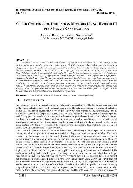
SPEED CONTROL OF INDUCTION MOTORS USING HYBRID PI PLUS FUZZY CONTROLLER
The conventional speed controllers for vector control of induction motor drive (VC1MD) suffer from the problem of stability; besides, these controllers such as PD/PID controllers show either steady state error or sluggish response to the perturbation in reference setting or during load perturbation. In this paper, one method has been implemented on a 3 phase, 50 HP(37KW), cage type induction motor . According to this, a PI plus Fuzzy hybrid controller is implemented. At first, the PI controller is investigated for speed control of Induction Motor then Hybridization of fuzzy logic (FL) and PI controller for the speed control of given motor is performed to remove the disadvantages of FL controller (steady-state error) and PI controller (overshoot and undershoot). For experimental analysis, we have used MATLAB SIMULINK of Induction Motor. According to the simulation results, hybrid controller creates better performance in terms of rise time, overshoot, undershoot and settling time .The Comparison analysis shows that in the PI controller it requires more settling time and steady state speed error but the speed response with this controller has no overshoot and settles faster in comparison with FL controller and it improves the torque disturbances rejections .
The conventional speed controllers for vector control of induction motor drive (VC1MD) suffer from the problem of stability; besides, these controllers such as PD/PID controllers show either steady state error or sluggish response to the perturbation in reference setting or during load perturbation. In this paper, one method has been implemented on a 3 phase, 50 HP(37KW), cage type induction motor . According to this, a PI plus Fuzzy hybrid controller is implemented. At first, the PI controller is investigated for speed control of Induction Motor then Hybridization of fuzzy logic (FL) and PI controller for the speed control of given motor is performed to remove the disadvantages of FL controller (steady-state error) and PI controller (overshoot and undershoot). For experimental analysis, we have used MATLAB SIMULINK of Induction Motor. According to the simulation results, hybrid controller creates better performance in terms of rise time, overshoot, undershoot and settling time .The Comparison analysis shows that in the PI controller it requires more settling time and steady state speed error but the speed response with this controller has no overshoot and settles faster in comparison with FL controller and it improves the torque disturbances rejections .

Create successful ePaper yourself
Turn your PDF publications into a flip-book with our unique Google optimized e-Paper software.
International Journal of Advances in Engineering & Technology, Nov. 2013.<br />
©IJAET ISSN: 22311963<br />
<strong>SPEED</strong> <strong>CONTROL</strong> <strong>OF</strong> <strong>INDUCTION</strong> <strong>MOTORS</strong> <strong>USING</strong> <strong>HYBRID</strong> <strong>PI</strong><br />
<strong>PLUS</strong> <strong>FUZZY</strong> <strong>CONTROL</strong>LER<br />
Gauri V. Deshpande 1 and S.S.Sankeshwari 2<br />
1, 2<br />
PG Department MBES COE, Ambajogai, India<br />
ABSTRACT<br />
The conventional speed controllers for vector control of induction motor drive (VC1MD) suffer from the<br />
problem of stability; besides, these controllers such as PD/<strong>PI</strong>D controllers show either steady state error or<br />
sluggish response to the perturbation in reference setting or during load perturbation. In this paper, one method<br />
has been implemented on a 3 phase, 50 HP(37KW), cage type induction motor . According to this, a <strong>PI</strong> plus<br />
Fuzzy hybrid controller is implemented. At first, the <strong>PI</strong> controller is investigated for speed control of Induction<br />
Motor then Hybridization of fuzzy logic (FL) and <strong>PI</strong> controller for the speed control of given motor is performed<br />
to remove the disadvantages of FL controller (steady-state error) and <strong>PI</strong> controller (overshoot and undershoot).<br />
For experimental analysis, we have used MATLAB SIMULINK of Induction Motor. According to the simulation<br />
results, hybrid controller creates better performance in terms of rise time, overshoot, undershoot and settling<br />
time .The Comparison analysis shows that in the <strong>PI</strong> controller it requires more settling time and steady state<br />
speed error but the speed response with this controller has no overshoot and settles faster in comparison with<br />
FL controller and it improves the torque disturbances rejections .<br />
KEYWORDS: Induction Motor Indirect Vector Control, Hybrid Controller (<strong>PI</strong>+FL).<br />
I. INTRODUCTION<br />
An induction motor is an asynchronous AC (alternating current) motor. The least expensive and most<br />
widely used induction motor is the squirrel cage motor. The interest in sensor less drives of induction<br />
motor (IM) has grown significantly over the past few years due to some of their advantages, such as<br />
mechanical robustness, simple construction, and less maintenance. These applications include pumps<br />
and fans, paper and textile mills, subway and locomotive propulsions, electric and hybrid vehicles,<br />
machine tools and robotics, home appliances, heat pumps and air conditioners, rolling mills, wind<br />
generation systems, etc. So, Induction motors have been used more in the industrial variable speed<br />
drive system with the development of the vector control technology. This method requires a speed<br />
sensor such as shaft encoder for speed control.<br />
The control and estimation of ac drives in general are considerably more complex than those of dc<br />
drives, and this complexity increases substantially if high performances are demanded. The main<br />
reasons for this complexity are the need of variable-frequency, harmonically optimum converter<br />
power supplies, the complex dynamics of ac machines, machine parameter variations, and difficulties<br />
of processing feedback signals in the presence of harmonic <strong>PI</strong> controller can never achieve perfect<br />
control, that is, keep the speed of induction motor continuously at the desired set point value in the<br />
presence of disturbance or set point changes. Therefore, an advanced control technique such as fuzzy<br />
logic controller is needed. Fuzzy systems are applied in wide range of academic and industrial fields<br />
such as modelling and control, signal possessing, medicine, and etc. An important Fuzzy Logic<br />
application is finding a new solution for control problems that will be discuses later. The present<br />
paper discusses a Fuzzy Logic Based intelligent controller. A Fuzzy Logic Controller (FLC) does not<br />
need complex mathematical algorithms and is based on the IF_THEN linguistic rules. Principle of<br />
vector control method is the use of coordinate transformation which to produce the same rotating<br />
magnetic potential and transformed the same power as the standard. It creates equivalent relation<br />
among a three-phase winding, two-phase AC windings and the rotation of the DC winding in order to<br />
2253 Vol. 6, Issue 5, pp. 2253-2261
International Journal of Advances in Engineering & Technology, Nov. 2013.<br />
©IJAET ISSN: 22311963<br />
seek the equivalent model of induction motor windings of the DC motor. To establish a Simulation<br />
model of induction motor vector control system can effectively save control system design time and<br />
validate the algorithm.<br />
Next section II describes the literature review regarding the methods of indirect vector control using<br />
fuzzy controllers. Section III and IV describes method of hybrid controller and related terminologies.<br />
Section V presents the experimental setup for further conclusions.<br />
II.<br />
RELATED WORK<br />
Basically, methods of speed control of induction motor are categorized into two types such as scalar<br />
control and vector control. Scalar control as the name indicates, is due to magnitude variation of the<br />
control variable only, and disregards the coupling effect in machine. For example, the voltage of<br />
machine can be controlled to control the flux, and frequency or slip can be controlled to control the<br />
torque. However flux and torque are also function of voltage and frequency respectively. Vector<br />
control was invented in the late 1960 [2]. The vector control is also known as decoupling, orthogonal,<br />
or trans- vector control. The higher order and coupling model of the machine that gives complex<br />
stability and sluggish response problems in a scalar controlled drive tend to vanish with vector<br />
control. The FOC schemes are classified into two groups: the direct method of field orientation and<br />
the indirect method of field orientation.<br />
Iulian Birou & Virgil Maeir [3] designed fuzzy controller is designed indirect vector control of an<br />
induction motor to achieve fast dynamic response and robustness for low and high speeds. Different<br />
types of membership functions of the linguistic variables and output/input characteristics are<br />
analyzed. A simple, but robust structure enables a wide range speed control of the driving system. The<br />
rotor flux field oriented control (FOC) is realized by using a flux observer based on the IM model<br />
with nonlinear parameters.<br />
Vinod Kumar, R. Joshi [4] presents a hybrid system controller, incorporating fuzzy controller with<br />
vector-control method for induction motors. The vector-control method has been optimized by using<br />
fuzzy controller instead of a simple P-I controller. High quality of the regulation process is achieved<br />
through utilization of the fuzzy logic controller, while stability of the system during transient<br />
processes and a wide range of operation are assured through application of the vector-control.<br />
Field orientation control (FOC) of induction machines has permitted fast transient response by<br />
decoupled torque and flux control. However, field orientation detuning caused by parameter<br />
variations is a major difficulty for indirect FOC methods. Traditional <strong>PI</strong>D controllers have trouble<br />
meeting a wide range of tracking performance even when proper field orientation is achieved. <strong>PI</strong>D<br />
performance is severely degraded when detuning occurs. Heber [5] presents a fuzzy logic design<br />
approach that will meet the speed tracking requirements even when detuning occurs.<br />
Ali Saghafinia, Hew W. Pinga & M. Nasir Uddin [6] presented a new design of fuzzy self-tuning<br />
hybrid fuzzy controller for IFOC induction motor drives. Induction motor drive with the appropriate<br />
design of hybrid fuzzy controller as speed controller could be high performance under steady state and<br />
transient state. In this hybrid fuzzy controller coefficients should be tuned for high performance and<br />
robust IM drive under steady and transient conditions. The results show the effectiveness of the<br />
proposed adaptive fuzzy self-tuning hybrid fuzzy controller (AFSHFC) based IM drive at different<br />
operating conditions.<br />
Fuzzy logic, unlike Boolean logic, deals with problems that have vagueness, uncertainty, or<br />
imprecision, and uses membership functions with values between 0 and 1 to solve the problem Fuzzy<br />
control, similar to expert system based control, is described by a set of IF-THEN production rules, and<br />
is often defined as fuzzy expert system[7]. In [8], fuzzy-logic-based intelligent controllers have been<br />
proposed for speed control of FOIM drives.<br />
Motivated by the successful development and application in [8] proposed a hybrid <strong>PI</strong>D + fuzzy<br />
controller consisting of a <strong>PI</strong>D controller and a fuzzy logic controller (FLC) in a serial arrangement for<br />
speed control of FOIM drives, more specifically, direct field-oriented IM (DFOIM) drives[9]. A.<br />
Mishra & P. Chaudhari [10] The presents indirect vector control using intelligent controller approach<br />
avoids the use of flux and speed sensor which increase the installation cost and mechanical<br />
robustness.<br />
2254 Vol. 6, Issue 5, pp. 2253-2261
International Journal of Advances in Engineering & Technology, Nov. 2013.<br />
©IJAET ISSN: 22311963<br />
III.<br />
<strong>SPEED</strong> <strong>CONTROL</strong> <strong>OF</strong> <strong>INDUCTION</strong> MOTOR<br />
3.1. Induction Motor Modelling<br />
The electrical part of an induction motor is represented with a fourth-order state-space model and the<br />
mechanical part with a second-order system. All electrical parameters and variables are referred to the<br />
stator. This is indicated by the prime symbols in the machine Equations (1) for electrical and<br />
mechanical systems. Figure 1 show all rotor and stator quantities are in the arbitrary two axis<br />
reference frame (d-q frame).<br />
Figure 1: Stator and rotor in two-axis reference frame (a) q-axis, and (b) d-axis<br />
V qs = R s i qs + d φ dt qs + wφ ds<br />
V ds = R s i ds + d φ dt ds − wφ qs<br />
′<br />
V qr = R ′ ′<br />
r i qr + d φ ′ ′<br />
dt qr + (w − w r )φ dr<br />
(1)<br />
′<br />
V dr = R ′ ′<br />
r i dr + d φ ′<br />
dt dr<br />
T e = 1. 5P(φ ds i qs − φ qs i ds )<br />
′ ′<br />
+ (w − w r )φ qr<br />
φ dr<br />
′<br />
φ qs = L s i qs + L m i qr<br />
′<br />
φ ds = L s i ds + L m i dr<br />
′<br />
φ qr = L ′ ′<br />
r i qr + L m i qs<br />
= L ′ ′<br />
r i dr<br />
L s = L ls + L m<br />
L ′ ′<br />
r = L lr + L m<br />
+ L m i ds<br />
The squirrel cage IM using direct and quadrature axes (d-q) theory in the stationary reference frame,<br />
which needs less variables and thus analysis becomes easy [11]. Figure 2 shows the block diagram of<br />
the indirect vector control technique. The drive is controlled with two control loops, i.e. internal pulse<br />
width modulation (PWM) current control loop and external speed control loop.<br />
The induction motor is fed by a current-controlled PWM inverter. This inverter operates as a threephase<br />
sinusoidal current source. The error between speed ω and the reference speed ω* (ω - ω*) is<br />
processed by the speed controller to produce a command torque T ∗ e . The rotor flux and torque can be<br />
independently controlled by the stator direct-axis current i ds and quadrature-axis current i qs ,<br />
∗<br />
respectively. The stator quadrature-axis current reference is i qs calculated from command torque T ∗ e as<br />
shown in Equation (2)<br />
∗<br />
i qs = 2 2 L r<br />
3 P L m<br />
T e<br />
⃒ψ r ⃒ est<br />
(2)<br />
Where L r is the rotor inductance, L m is the mutual inductance, and ⃒ψ r ⃒ est is the estimated rotor flux<br />
linkage given by Equation (3)<br />
⃒ψ r ⃒ est = L mi ds<br />
1+τ r s<br />
(3)<br />
2255 Vol. 6, Issue 5, pp. 2253-2261
International Journal of Advances in Engineering & Technology, Nov. 2013.<br />
©IJAET ISSN: 22311963<br />
Figure 2: Block diagram of the indirect vector control technique<br />
where τ r = L r ⁄ R r is the rotor time constant.<br />
∗<br />
The stator direct-axis current reference i ds is obtained by Equation (4) from rotor flux reference<br />
input⃒ψ r ⃒ ∗ .<br />
∗<br />
i ds<br />
= ⃒ψ r⃒ ∗<br />
L m<br />
(4)<br />
The rotor flux position θ e required for coordinates transformation is generated from the rotor speed<br />
w m and slip frequency w sl (Equation 5).<br />
θ e = ∫(w m + w sl ) dt (5)<br />
∗<br />
The slip frequency is calculated by Equation (6) from the stator reference current i ds and the motor<br />
parameters.<br />
w sl =<br />
L m ∗<br />
(6)<br />
R r<br />
i<br />
⃒ψ r ⃒ L qs<br />
est<br />
r<br />
∗<br />
current references are converted into phase current references i a ∗ , i b ∗ , i c<br />
∗<br />
for the current<br />
∗<br />
The i qs and i ds<br />
regulators. The regulators use the measured and reference currents to form the inverter gating signals.<br />
The speed controller keeps the motor speed equal to the reference speed input in steady state and<br />
provides a good dynamic during transient periods. The proportional integral (<strong>PI</strong>) controller can be<br />
used for speed control of IM. The <strong>PI</strong> and differential (<strong>PI</strong>D) controller is not normally used because<br />
differentiation could be causing the problem when input reference is a step. Usually, the difference of<br />
reference speed (w ∗ ) and actual speed(w), which is called the speed error, is given as input to the<br />
controller. The speed controller processes the speed error and gives torque value as an input. Then the<br />
torque value is fed to the limiter, which gives the final value of command torque. The speed error and<br />
change in speed error at n-th instant of time are as below:<br />
∗<br />
e (n) = w (n) − w (n) (7)<br />
∆e (n) = e (n) − e (n−1) (8)<br />
This paper presents the performance of three types of speed control methods for simulation study: <strong>PI</strong><br />
controller, fuzzy speed controller and hybrid controller (hybridization of fuzzy logic (FL) and <strong>PI</strong><br />
controller).<br />
IV.<br />
<strong>HYBRID</strong> <strong>CONTROL</strong>LER<br />
The hybrid controller module has two controllers combined <strong>PI</strong>-controller and Fuzzy Controller.<br />
4.1. <strong>PI</strong>-Controller<br />
2256 Vol. 6, Issue 5, pp. 2253-2261
International Journal of Advances in Engineering & Technology, Nov. 2013.<br />
©IJAET ISSN: 22311963<br />
Control law used for this strategy is given by<br />
T = Kp e + Ki ∫e dt (9)<br />
Its output is the updating in <strong>PI</strong> controller gains (Kp and Ki) based on a set of rules to maintain<br />
excellent control performance even in the presence of parameter variation and drive nonlinearity. At<br />
starting mode the high value of the error is amplified across the <strong>PI</strong> controller provoking high<br />
variations in the command torque. If the gains of the controller exceed a certain value, the variations<br />
in the command torque become too high and will destabilize the system. To overcome this problem, a<br />
limiter ahead of the <strong>PI</strong> controller is used [11]. This limiter causes the speed error to be maintained<br />
within the saturation limits provoking, when appropriately chosen, smooth variations in the command<br />
torque even when the <strong>PI</strong> controller gains are very high. The motor reaches the reference speed rapidly<br />
and without overshoot, step commands are tracked with almost zero steady state error and no<br />
overshoot, load disturbances are rapidly rejected and variations of some of the motor parameters are<br />
fairly well dealt.<br />
4.2. Fuzzy-Controller<br />
Table 1: Fuzzy variables<br />
E<br />
CE<br />
U N Z P<br />
N NB NM Z<br />
Z NM Z PM<br />
P Z PM PB<br />
The drawbacks of this <strong>PI</strong> controller are the occurrence of overshoot while starting, undershoot while<br />
load application and overshoot again while load removal [11]. In the fuzzification block, the inputs<br />
and outputs crisp variables are converted into fuzzy variables ‘e’, ‘de’ and ‘du’ using the triangular<br />
membership function shown in figure 3. The fuzzification block produces the fuzzy variables ‘e’ and<br />
‘de’ using their crisp counterpart. These fuzzy variables are then processed by an inference<br />
mechanism based on a set of control rules contained in (3*3) table as shown in Table 1. The fuzzy<br />
rules are expressed using the IF-THEN form. The crisp output of the FLC is obtained by using MAX-<br />
MIN inference algorithm and the center of gravity de-fuzzification approach. The performance of the<br />
fuzzy controller depends on the membership functions, their distribution and the fuzzy rules that<br />
describe the control algorithm. There is no formal method to determine the parameters of the<br />
controller accurately. In this controller, FL is used for pre-compensation [12, 13, 15, 16] of reference<br />
speed, which means that the reference speed signal ( w ∗ ) is changed in advance in accordance with<br />
the rotor speed, so that a new reference speed signal (w1 ∗ ) is obtained and the main control action is<br />
performed by <strong>PI</strong> controller. The speed error (e(n) ∗ ) and the change in speed error are the inputs to the<br />
FL, the output of the FL controller is added to the reference speed to generate a pre-compensated<br />
reference speed, which is to be used as a reference speed signal by the <strong>PI</strong> controller. Figure 4 shows<br />
membership function for control variables.<br />
Figure 3: Membership function for Input variables<br />
2257 Vol. 6, Issue 5, pp. 2253-2261
International Journal of Advances in Engineering & Technology, Nov. 2013.<br />
©IJAET ISSN: 22311963<br />
V. SIMULATION RESULTS<br />
Figure 4: Membership function for Control variable<br />
A complete mathematical model of FOC induction motor with a 50 HP (37KW) is simulated in<br />
MATALAB-SIMULINK. The performance of FOC drive with proportional plus integral (<strong>PI</strong>)<br />
controller are presented and analysed. One common linear control strategy is proportional-integral<br />
(<strong>PI</strong>) control. The Induction motor used in this is a 50 HP, 460 V, four-pole, 60 Hz motor having the<br />
following parameters:<br />
Table 2: Parameter Values<br />
Rated Power (P) 50 Hp<br />
Voltage 460 V<br />
R s 0.087Ω<br />
L ls<br />
0.8mH<br />
L m<br />
34.7mH<br />
R r<br />
0.228 Ω<br />
L lr<br />
0.8mH<br />
The simulation results are done in two mode, the starting mode and dynamic mode. In the dynamic<br />
mode, the reference speed goes up from 120 (rad/s) to 160 (rad/s) at t=0.3 (s).<br />
Figure 5: SIMULINK Model of Induction motor using hybrid <strong>PI</strong> -Fuzzy controller<br />
The <strong>PI</strong> speed controller gains in (9) are selected by trial and error basis by observing their effects on<br />
the response of the drive. Figure 5 shows complete SIMULINK Model. The results of hybrid speed<br />
controller are shown in Figure 6 and Figure 7.<br />
2258 Vol. 6, Issue 5, pp. 2253-2261
International Journal of Advances in Engineering & Technology, Nov. 2013.<br />
©IJAET ISSN: 22311963<br />
Figure 6: Speed Response of Induction Motor using <strong>PI</strong> -Control.<br />
Figure 7: Speed Response of Induction Motor using hybrid <strong>PI</strong>-fuzzy Control.<br />
Table 3 shows the comparison results of <strong>PI</strong> and <strong>PI</strong>-Fuzzy Controller in terms of rise time and Settling<br />
Time. Comparison shows that, Good torque response is obtained with hybrid controller at all the<br />
instants. Less oscillation occurred in the torque response with Hybrid controller compared to <strong>PI</strong><br />
Controller.<br />
Table 3: Comparison between <strong>PI</strong> and <strong>PI</strong>-Fuzzy Controller<br />
Controller Rise Time(Tr) Settling Time(Ts)<br />
<strong>PI</strong>-Controller 0.2 0.45<br />
<strong>PI</strong>-Fuzzy Controller 0.1 0.25<br />
2259 Vol. 6, Issue 5, pp. 2253-2261
International Journal of Advances in Engineering & Technology, Nov. 2013.<br />
©IJAET ISSN: 22311963<br />
Figure 8: Torque Response of Induction Motor using <strong>PI</strong>-Control.<br />
VI.<br />
Figure 9: Torque Response of Induction Motor using hybrid <strong>PI</strong>-fuzzy Control.<br />
CONCLUSION<br />
The proposed controller has exhibited the combined advantages of a <strong>PI</strong> controller and a FLC. Hybrid<br />
controller produces better performances in terms of rise time, overshoot, undershoot and settling time.<br />
There is no steady-state error in the speed response during the operation. Good torque response is<br />
obtained with hybrid controller at all time instants and speed response is better than FL and <strong>PI</strong><br />
controllers. The speed response with this controller has no overshoot and settles faster in comparison<br />
with FL controller. It is also noted that there is no steady-state error in the speed response during the<br />
operation when hybrid controller is activated. Good torque response is obtained with hybrid controller<br />
at all time instants and speed response is better than FL and <strong>PI</strong> controllers. There is a negligible ripple<br />
in speed response at hybrid controller in comparison with <strong>PI</strong> and FL controllers.<br />
REFERENCES<br />
[1]. Leonhard, W. (1995),” Controlled AC Drives: A Successful Transfer from Ideas to Industrial Practice”,<br />
CETTI, pp1-12.<br />
[2]. A.Mechernene, M.Zerikat & M.Hachblef, “Fuzzy Speed Regulation for Induction Motor Associated<br />
With Field-Oriented Control”, IJSTA, Vol. 2, pp 804-817.<br />
[3]. I. Birou & V. Maeir (2009),” Indirect Vector Control of an Induction Motor with Fuzzy-Logic based<br />
Speed Controller”, 3rd International Symposium on Electrical Engineering and Energy Converters,<br />
pp149-154.<br />
2260 Vol. 6, Issue 5, pp. 2253-2261
International Journal of Advances in Engineering & Technology, Nov. 2013.<br />
©IJAET ISSN: 22311963<br />
[4]. V. Kumar & R. Joshi (2005),” Hybrid Controller based Intelligent Speed Control of Induction Motor”,<br />
in the Journal of Theoretical and Applied Information Technology, pp71-75.<br />
[5]. B. Heber, Et Al.(1997), “Fuzzy Logic Enhanced Speed Control Of An Indirect Field-Oriented<br />
Induction Machine Drive,” IEEE Trans. Power Electronics, Vol. 12, No. 5, pp772 – 778.<br />
[6]. A. Saghafinia ,H. Ping & M. Uddin (2013),” Designing Self-Tuning Mechanism On Hybrid Fuzzy<br />
Controller For High Performance And Robust Induction Motor Drive”, in the International Journal of<br />
Advanced Technology & Engineering Research, Vol.3, No.2,pp65-72.<br />
[7]. Driankov D., Hellendoorn, H & Reinfrank, M., “An Introduction To Fuzzy Control”, Springer, Verlag,<br />
1997.<br />
[8]. I. Miki, Et Al .(1991) “Vector Control Of Induction Motor With Fuzzy <strong>PI</strong> Controller,” IEEE<br />
Conference, IAS Annu. Meeting, Vol. 1, pp341-346.<br />
[9]. T. Ho & L. Yeh (2010),” Design Of A Hybrid <strong>PI</strong>D Plus Fuzzy Controller For Speed Control Of<br />
Induction Motors”, 5Th IEEE Conference On Industrial Electronics And Applications.<br />
[10]. A. Mishra & P. Choudhary (2012), “ Speed Control Of An Induction Motor By Using Indirect Vector<br />
Control Method” ,in the International Journal of Emerging Technology and Advanced Engineering,<br />
Vol.2, No.12.<br />
[11]. Radha Thangaraj, Thanga Raj Chelliah, Et Al. (2010), “Optimal Gain Tuning of <strong>PI</strong> Speed Controller in<br />
Induction Motor Drives Using Particle Swarm Optimization”, published by Oxford University Press.<br />
[12]. J.Kim, K.C. Kim & E. K. P. Chong (1994), “Fuzzy Pre-Compensated <strong>PI</strong>D Controllers, IEEE<br />
Transactions On Control System, vol.2, pp406-411.<br />
[13]. S.W. Lee,S.Kim & Y.Park,(1998) ,“Fuzzy Pre-Compensated <strong>PI</strong> Controller For A Variable Capacity<br />
Heat Pump”, In proceedings of the IEEE Conference on control Applications, pp953-957.<br />
[14]. B.Singh &G.Choudhuri,(2002) “Fuzzy Logic Based Speed Controllers For Vector Controlled Induction<br />
Motor Drive”, IETE Journal of Research, 48, pp441-447.<br />
[15]. C. Thanga Raj, S.P. Stivastava & P. Agarwal,(2009) “Particle Swarm And Fuzzy Logic Based Optimal<br />
Energy Control Of Induction Motor For A Mine Hoist Load Diagram”, IAENG International Journal<br />
of Computer Science, Vol.36, pp17-25.<br />
[16]. K. V. Naresh, (2007),”Investigation of SVM-PWM based Induction Motor Drives”, M Tech<br />
Dissertation, IIT Roorkee.<br />
AUTHOR’S BIOGRAPHY<br />
Gauri Vijaykumar Deshpande completed B. E. (Electrical Engineering) and pursuing M.<br />
E. (Control System) and presently working as a lecturer in M.B.E.S’s College Of<br />
Engineering, Ambajogai, India.<br />
Subhash. S. Sankeshwari received his B. E. (Electrical Engineering), from K.L.E’s<br />
College of Engineering Belgaon and M. E. (Control System) from W C E, Sangli. He is<br />
pursuing PhD from S. R. T. M. University, Nanded. Presently he is working as Asst.<br />
Professor and Head of the Electrical, Electronics & Power Engineering Dept. in M.B.E.S’s<br />
College of Engineering, Ambajogai, India.<br />
2261 Vol. 6, Issue 5, pp. 2253-2261