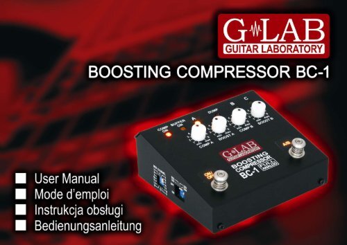
Boosting Compressor BC-1 User Manual - G LAB
Boosting Compressor BC-1 User Manual - G LAB
Boosting Compressor BC-1 User Manual - G LAB

You also want an ePaper? Increase the reach of your titles
YUMPU automatically turns print PDFs into web optimized ePapers that Google loves.
Table of contents<br />
Version 1.0<br />
Structure __________________________________________________________ 4<br />
Power supply ______________________________________________________ 6<br />
MODE switch ______________________________________________________ 7<br />
Way of connecting __________________________________________________ 7<br />
GAIN switch _______________________________________________________ 8<br />
Footswitches ______________________________________________________ 9<br />
Compression and boost level ________________________________________ 10<br />
Clean tone________________________________________________________ 11<br />
Crunch and overdrive tones _________________________________________ 12<br />
Using with an amp with distorted power amp___________________________ 12<br />
Using with multi-channel amp _______________________________________ 13<br />
Buffer function ____________________________________________________ 14<br />
MIDI controlling ___________________________________________________ 15<br />
Technical parameters ______________________________________________ 17<br />
FCC Compliance___________________________________________________ 18<br />
Declaration of Conformity ___________________________________________ 19<br />
1
Dear Customer!<br />
Thank you for choosing our product.<br />
G <strong>LAB</strong> <strong>Boosting</strong> <strong>Compressor</strong> (<strong>BC</strong>-1) is a compressor type guitar effect which can<br />
be used as booster or as a booster-compressor.<br />
Basic features:<br />
- Analog compression circuit with opto component<br />
- Compression circuit matched to the electric and bass guitar in terms of signal<br />
and time<br />
- Two sets (A and B) of signal compression and boost regulators<br />
- Compression level indicator (DUMP)<br />
- Ultra low noise level enabling to work as a booster and/or booster-compressor<br />
on crunch and overdrive tones<br />
- Two footswitches: effect ON/OFF and compressor A/B<br />
- Work MODE switch: electric and bass guitar<br />
- Optical TRUE BYPASS and signal buffer mode<br />
- Four work modes of footswitches<br />
- Input sensitivity range switch (GAIN)<br />
- MIDI input for connecting foot controllers e.g. G <strong>LAB</strong> GSC.<br />
3
Structure<br />
4
1 - COMP ON indicator 7 - COMP C ON indicator<br />
2 - BUFFER ON indicator 8 - COMP B ON indicator<br />
3 - COMP A ON indicator 9 - DUMP - compression level indicator<br />
4 - COMP A level knob 10 - BOOST B level knob<br />
5 - BOOST A level knob 11 - COMP B level knob<br />
6 - ON/OFF footswitch 12 - compressor A/B switch<br />
18 - GAIN - sensitivity switch 20 - MIDI channel switch<br />
19 - MODE - work mode switch 21 - DS1 - DS4 switches<br />
5
13 - IN signal connector 15 - 9V power supply connector<br />
14 - OUT signal connector 16 - MIDI IN input<br />
17 - MIDI THRU output<br />
Power supply<br />
The <strong>BC</strong>-1 should be supplied from external regulated 9V DC power supply,<br />
with capacity of 40 mA or more. It is recommended to use separated source e.g. G <strong>LAB</strong><br />
6
PB-1 in order to avoid ground loop. Before connecting please check if the connector’s<br />
polarization is CTR – (center negative).<br />
The <strong>BC</strong>-1 is protected against opposite polarity. If this protection switches on<br />
it is needed to disconnect the power supply and wait few minutes before reactivation<br />
of the device.<br />
ATTENTION: Damages caused by improper power supply causes loss of<br />
the warranty.<br />
MODE switch<br />
MODE switch enables to match the compressor release time to the electric<br />
(GUITAR) or bass guitar (BASS).<br />
Way of connecting<br />
It is recommended to connect the <strong>BC</strong>-1 as the first stompbox after a wah-wah<br />
effect in the effects chain.<br />
7
GAIN switch<br />
GAIN switch enables to match the compressor sensitivity to the guitar signal.<br />
If you play the guitar with minimum one humbucker the GAIN switch should be set on<br />
LOW position. If the guitar signal is too low to get needed compression level (e.g. when<br />
the guitar has only SINGLE COIL pickups) GAIN switch should be set on HIGH position<br />
(the sensitivity is two times bigger then).<br />
8
Current compression level is indicated by DUMP indicator (the brighter it lights<br />
the bigger is signal compression).<br />
For the bass guitar the procedure is similar. If you play the bass guitar with active<br />
pickups or/and humbucker the GAIN switch should be set on LOW position. If you play<br />
the bass guitar with passive pickups, especially the single coil ones, the GAIN switch<br />
should be set on HIGH position.<br />
Footswitches<br />
The <strong>BC</strong>-1 features effect ON/OFF and compressor A/B selection footswitches.<br />
The DS3 and DS4 switches enable to change the footswitches’ function.<br />
9
In work modes No. 1 and No. 2 left footswitch has a function of activating<br />
and deactivating the effect and the right footswitch enables switching between<br />
the A and B compressors (in work mode No. 1) or A, B and C compressors (in work<br />
mode No. 2).<br />
In work mode No. 3 the compressor is permanently activated and the left footswitch<br />
serves to choose the A compressor and the right one serves to choose<br />
the B compressor.<br />
In work mode No. 4 the compressor is permanently activated and the left footswitch<br />
serves to switch to „lower” compressor (C to B and B to A) and the right one serves<br />
to switch on „higher” compressor (A to B and B to C).<br />
Compression and boost level<br />
To set the compression level serves the COMP knob and to set the boost level<br />
serves the BOOST knob. The <strong>BC</strong>-1 posses two sets of regulators and the choice<br />
of them is indicated by lighting of corresponding A or B indicator.<br />
10
Lighting of C indicator signifies activation of the compressor with maximal compression<br />
and boost levels.<br />
Clean tone<br />
It is recommended to start setting of the <strong>BC</strong>-1 by setting the COMP level on<br />
the minimum and the BOOST level on the value No. 4. The test of sound should be<br />
done with guitar volume knob set on maximum. It is recommended to increase<br />
the compression level with COMP knob and the decrease of the volume should<br />
11
e compensated by the increase of the BOOST. The <strong>BC</strong>-1 enables to obtain big signal<br />
compression without the „pump” or „breath” effect.<br />
If you play with C compressor it is recommended to set the A compressor on lower<br />
compression level than B compressor is set on.<br />
Crunch and overdrive tones<br />
It is recommended to use the <strong>BC</strong>-1 on the crunch and overdriven tones<br />
as a booster with limiting the signal level by compressor. On the crunch tone you will<br />
get the effect of the sound sustain without increasing of the overdrive level. On the<br />
overdriven tones the sound will be more selective and the real guitar tone will be better<br />
heard. For high gain tones it is recommended to use the C compressor what can<br />
require to decrease the amp GAIN by a half (about 6 dB).<br />
Using with an amp with distorted power amp<br />
The <strong>BC</strong>-1 enables to obtain three basic tones: clean, crunch and overdrive<br />
on tube amps with distorted power amp. It is recommended to set the regulators as on<br />
the picture below and to choose 4th working mode of the footswitches.<br />
12
The A compressor becomes then a clean or delicate crunch channel (setting<br />
the BOOST knob on the value below 4th enables to attenuate the signal).<br />
The B compressor is then a crunch channel and the C compressor becomes<br />
an overdriven channel. Because of the signal boosting the compressor improves<br />
the sound quality of the effects connected between the <strong>BC</strong>-1 and an amp input.<br />
Using with multi-channel amp<br />
If you use a multi-channel amp the <strong>BC</strong>-1 enables to enlarge the quantity<br />
of available sounds by the combination of channel and compressor (A, B or C)<br />
selection. In this case the best solution is to use a MIDI controller (e.g. G <strong>LAB</strong> GSC-2/3)<br />
to control simultaneously an amp and the compressor.<br />
13
Buffer function<br />
The <strong>BC</strong>-1 posses a buffer that enables to boost the guitar signal power (without<br />
the voltage increase) and has input impedance same as the tube amps (find more<br />
at http://www.glab.com.pl/tips). The buffer can be activated in place of the BYPASS<br />
function when the DS-1 switch is set to ON position.<br />
14
MIDI controlling<br />
To set the MIDI channel on which the <strong>BC</strong>-1 receives the commands serves<br />
the MIDI CHANNEL rotary switch. To set the channel it is needed to use a small flat<br />
screwdriver and to turn right or left the middle part of the switch. The arrow-head<br />
indicates the set channel.<br />
The <strong>BC</strong>-1 can be controlled by Program Change and/or Control Change commands.<br />
15
The tables below show the functionality of Program Change and Control Change<br />
commands.<br />
16
Technical parameters<br />
Dimensions: depth 120 mm<br />
width<br />
120 mm<br />
height<br />
60 mm<br />
Weight<br />
0,56 kg<br />
Input impedance<br />
1 MΩ<br />
Maximal input signal<br />
0 dBu (GAIN LOW), - 4 dBu (GAIN HIGH)<br />
Output impedance<br />
700 Ω<br />
Power supply<br />
9V DC (8,7 to 9,4V regulated)<br />
Current consumption<br />
40 mA<br />
17
FCC Compliance<br />
This device complies with Part 15 of the FCC Rules. Operation is subject to<br />
the following two conditions: (1) this device may not cause harmful interference, and (2)<br />
this device must accept any interference received, including interference that may cause<br />
undesired operation.<br />
NOTE: This equipment has been tested and found to comply with the limits for a Class<br />
B digital device, pursuant to Part 15 of the FCC Rules. These limits are designed<br />
to provide reasonable protection against harmful interference in a residential<br />
installation. This equipment generates, uses and can radiate radio frequency energy<br />
and, if not installed and used in accordance with the instructions, may cause harmful<br />
interference to radio communications. However, there is no guarantee that interference<br />
will not occur in a particular installation.<br />
If this equipment does cause harmful interference to radio or television reception, which<br />
can be determined by turning the equipment off and on, the user is encouraged to try<br />
to correct the interference by one or more of the following measures:<br />
– Reorient or relocate the receiving antenna.<br />
– Increase the separation between the equipment and receiver.<br />
– Connect the equipment into an outlet on a circuit different from that to which the<br />
receiver is connected.<br />
– Consult the dealer for help.<br />
18
Declaration of Conformity<br />
ELZAB S.A., ul. Kruczkowskiego 39, 41-813 Zabrze, Poland,<br />
declare under sole responsibility, that the following product:<br />
G <strong>LAB</strong>/<strong>Boosting</strong> <strong>Compressor</strong> <strong>BC</strong>-1 (G <strong>LAB</strong> <strong>BC</strong>-1)<br />
conforms with requirements of the EC Council Directives:<br />
● 2006/95/EEC Low Voltage Directive,<br />
● 2004/108/EEC Electromagnetic Compatibility,<br />
and holds CE mark. Above named product conforms with the following standards:<br />
● PN-EN 60065:2004 /EN 60065:2002/ Audio, video and similar apparatus -<br />
Safety requirements.<br />
● PN-EN 55103-1:2000 /EN 55103-1:1996/ Electromagnetic compatibility -<br />
Product family standard for audio, video, audio-visual and entertainment<br />
lighting control apparatus for professional use - Part 1: Emission<br />
● PN-EN 55103-2:2001 /EN 55103-2:1996/ Electromagnetic compatibility -<br />
Product family standard for audio, video, audio-visual and entertainment<br />
lighting control apparatus for professional use - Part 2: Immunity<br />
Jerzy Biernat<br />
President of the ELZAB S.A. Board of Directors<br />
Copy of original EC declaration of conformity is available for download on our<br />
webside http://www.glab.com.pl<br />
19
DO NOT PLACE THIS PRODUCT INTO THE WASTE CONTAINER !<br />
This device is marked with a cross-lined waste container symbol<br />
according to 2002/96/EU Directive on Waste Electric<br />
and Electronic Equipment.<br />
Such marking informs that after usage equipment can not be<br />
trashed together with other household waste.<br />
An user obligation is to return wasted equipment to a party collecting wasted<br />
electric and electronic equipment. Parties collecting such equipment organize<br />
a system, including local collection points, shops and other units, allowing<br />
to return such equipment. This Directive assures an user free of charge<br />
utilization of such delivered equipment.<br />
This device is made of materials which can be recycled or utilized after<br />
becoming out of use. Proper handling of wasted electric and electronic<br />
equipment reduce demand for row materials and contribute in avoiding harmful<br />
consequences for environment and health of people caused by dangerous<br />
components and not proper storing and utilizing of such equipment.<br />
<strong>User</strong>’s manual Drawing No. G53INA00<br />
20