A Brief Review of Elasticity and Viscoelasticity for Solids 1 Introduction
A Brief Review of Elasticity and Viscoelasticity for Solids 1 Introduction
A Brief Review of Elasticity and Viscoelasticity for Solids 1 Introduction

Create successful ePaper yourself
Turn your PDF publications into a flip-book with our unique Google optimized e-Paper software.
Advances in Applied Mathematics <strong>and</strong> Mechanics<br />
Adv. Appl. Math. Mech., Vol. 3, No. 1, pp. 1-51<br />
DOI: 10.4208/aamm.10-m1030<br />
February 2011<br />
REVIEW ARTICLE<br />
A <strong>Brief</strong> <strong>Review</strong> <strong>of</strong> <strong>Elasticity</strong> <strong>and</strong> <strong>Viscoelasticity</strong><br />
<strong>for</strong> <strong>Solids</strong><br />
Harvey Thomas Banks 1,∗ , Shuhua Hu 1 <strong>and</strong> Zackary R. Kenz 1<br />
1 Center <strong>for</strong> Research in Scientific Computation <strong>and</strong> Department <strong>of</strong> Mathematics,<br />
North Carolina State University, Raleigh, NC 27695-8212, USA<br />
Received 25 May 2010; Accepted (in revised version) 31 August 2010<br />
Available online 15 October 2010<br />
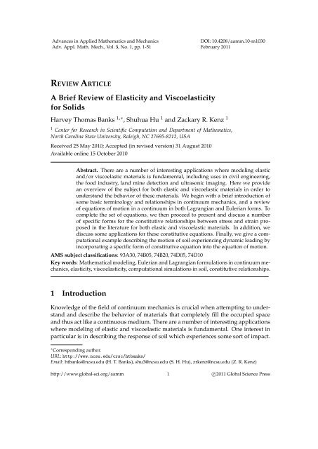
Abstract. There are a number <strong>of</strong> interesting applications where modeling elastic<br />
<strong>and</strong>/or viscoelastic materials is fundamental, including uses in civil engineering,<br />
the food industry, l<strong>and</strong> mine detection <strong>and</strong> ultrasonic imaging. Here we provide<br />
an overview <strong>of</strong> the subject <strong>for</strong> both elastic <strong>and</strong> viscoelastic materials in order to<br />
underst<strong>and</strong> the behavior <strong>of</strong> these materials. We begin with a brief introduction <strong>of</strong><br />
some basic terminology <strong>and</strong> relationships in continuum mechanics, <strong>and</strong> a review<br />
<strong>of</strong> equations <strong>of</strong> motion in a continuum in both Lagrangian <strong>and</strong> Eulerian <strong>for</strong>ms. To<br />
complete the set <strong>of</strong> equations, we then proceed to present <strong>and</strong> discuss a number<br />
<strong>of</strong> specific <strong>for</strong>ms <strong>for</strong> the constitutive relationships between stress <strong>and</strong> strain proposed<br />
in the literature <strong>for</strong> both elastic <strong>and</strong> viscoelastic materials. In addition, we<br />
discuss some applications <strong>for</strong> these constitutive equations. Finally, we give a computational<br />
example describing the motion <strong>of</strong> soil experiencing dynamic loading by<br />
incorporating a specific <strong>for</strong>m <strong>of</strong> constitutive equation into the equation <strong>of</strong> motion.<br />
AMS subject classifications: 93A30, 74B05, 74B20, 74D05, 74D10<br />
Key words: Mathematical modeling, Eulerian <strong>and</strong> Lagrangian <strong>for</strong>mulations in continuum mechanics,<br />
elasticity, viscoelasticity, computational simulations in soil, constitutive relationships.<br />
1 <strong>Introduction</strong><br />
Knowledge <strong>of</strong> the field <strong>of</strong> continuum mechanics is crucial when attempting to underst<strong>and</strong><br />
<strong>and</strong> describe the behavior <strong>of</strong> materials that completely fill the occupied space<br />
<strong>and</strong> thus act like a continuous medium. There are a number <strong>of</strong> interesting applications<br />
where modeling <strong>of</strong> elastic <strong>and</strong> viscoelastic materials is fundamental. One interest in<br />
particular is in describing the response <strong>of</strong> soil which experiences some sort <strong>of</strong> impact.<br />
∗ Corresponding author.<br />
URL: http://www.ncsu.edu/crsc/htbanks/<br />
Email: htbanks@ncsu.edu (H. T. Banks), shu3@ncsu.edu (S. H. Hu), zrkenz@ncsu.edu (Z. R. Kenz)<br />
http://www.global-sci.org/aamm 1 c⃝2011 Global Science Press
2 H. T. Banks, S. H. Hu <strong>and</strong> Z. R. Kenz / Adv. Appl. Math. Mech., 3 (2011), pp. 1-51<br />
This may result from buildings falling or being imploded, or even an intentionally introduced<br />
impact as part <strong>of</strong> l<strong>and</strong> mine detection ef<strong>for</strong>ts (see [54, 56]). The chief interest<br />
is in determining what would happen to buried objects given a particular surface impact.<br />
In the case <strong>of</strong> a building implosion, there are concerns <strong>for</strong> buried infrastructure<br />
such as tunnels, pipes, or nearby building infrastructure. Investigations can be carried<br />
out to determine the likely <strong>for</strong>ces on these buried objects to ensure that the <strong>for</strong>ce delivered<br />
into the soil will not damage other infrastructure. When detecting l<strong>and</strong> mines,<br />
the methodology developed in the papers cited uses an impact on the ground to create<br />
Rayleigh surface waves that are subsequently changed upon interacting with a<br />
buried mine; this change in wave <strong>for</strong>m might be detected through electromagnetic or<br />
acoustic means. Creating a model that accurately describes these Rayleigh waves is<br />
key to modeling <strong>and</strong> underst<strong>and</strong>ing the buried l<strong>and</strong> mine situation. In both <strong>of</strong> these<br />
examples, one must study the soil properties, determine a valid constitutive relationship<br />
<strong>for</strong> the soil, <strong>and</strong> verify the accuracy <strong>of</strong> the model. One can then use the models<br />
to predict the results from different <strong>for</strong>ces, soil properties, etc. Another application is<br />
the non-invasive detection <strong>of</strong> arterial stenosis (e.g., see [1, 3, 11, 38, 50]). In this study,<br />
blockages in the artery create turbulence in the blood flow, which then generates an<br />
acoustic wave with a normal <strong>and</strong> shear component. The acoustic wave propagates<br />
through the chest cavity until it reaches the chest wall, where a series <strong>of</strong> sensors detect<br />
the acceleration <strong>of</strong> the components <strong>of</strong> the wave. The data from the sensors can then be<br />
used to quickly determine the existence <strong>and</strong> perhaps the location <strong>of</strong> the blockages in<br />
the artery. This technique is inexpensive <strong>and</strong> non-invasive. For such a technology to<br />
be feasible, a mathematical model that describes the propagation <strong>of</strong> the acoustic wave<br />
from the stenosis to the chest wall will be necessary to correctly detect the location <strong>of</strong><br />
a blockage.<br />
The goal <strong>of</strong> this paper is to provide a brief introduction <strong>of</strong> both elastic <strong>and</strong> viscoelastic<br />
materials <strong>for</strong> those researchers with little or no previous knowledge on continuum<br />
mechanics but who are interested in studying the mechanics <strong>of</strong> materials. The<br />
materials that we are considering are simple (<strong>for</strong> example the stress at a given material<br />
point depends only on the history <strong>of</strong> the first order spatial gradient <strong>of</strong> the de<strong>for</strong>mation<br />
in a small neighborhood <strong>of</strong> the material point <strong>and</strong> not on higher order spatial<br />
gradients) <strong>and</strong> non-aging (the microscopic changes during an experiment can be neglected<br />
in the basic model). Our presentation is part tutorial, part review but not a<br />
comprehensive survey <strong>of</strong> a truly enormous research literature. We rely on parts <strong>of</strong> the<br />
st<strong>and</strong>ard literature <strong>and</strong> discuss our view <strong>of</strong> generally accepted concepts. We present<br />
a discussion <strong>of</strong> topics we have found useful over the past several decades; hence approximately<br />
20% <strong>of</strong> references are work from our group. We have not meant to ignore<br />
major applications in the many fine contributions <strong>of</strong> others; rather our presentation<br />
reflects a certain level <strong>of</strong> com<strong>for</strong>t in writing about ef<strong>for</strong>ts on which we have detailed<br />
knowledge <strong>and</strong> experience.<br />
The introductory review is outlined as follows: in Section 2 some basic terminology<br />
(such as stress <strong>and</strong> strain) <strong>and</strong> relationships (e.g., the relationship between strain<br />
<strong>and</strong> displacement) <strong>of</strong> continuum mechanics are briefly described. In addition, we give
H. T. Banks, S. H. Hu <strong>and</strong> Z. R. Kenz / Adv. Appl. Math. Mech., 3 (2011), pp. 1-51 3<br />
a brief overview <strong>of</strong> equations that describe the general motion <strong>of</strong> a continuous material<br />
in both Eulerian <strong>and</strong> Lagrangian <strong>for</strong>ms which describe motion utilizing a general relationship<br />
between stress <strong>and</strong> strain <strong>for</strong> materials. We thus must introduce constitutive<br />
relationships (see Section 3) in order to quantify the material dependent relationship<br />
between stress <strong>and</strong> strain. A wide number <strong>of</strong> approaches to model these constitutive<br />
relationships have been developed <strong>and</strong> we focus much <strong>of</strong> our attention here on these.<br />
Once constitutive relationships are determined one can in principle solve the resulting<br />
set <strong>of</strong> motion equations with proper boundary <strong>and</strong> initial conditions. We conclude the<br />
paper in Section 4 by giving an example describing the motion <strong>of</strong> soil experiencing<br />
dynamic loading.<br />
We remark that all <strong>of</strong> the considerations here are under isothermal conditions; in<br />
most physical problems where energy considerations (heat flow, temperature effects,<br />
entropy, etc.) are important, one may need to treat thermoelastic/thermoviscoelastic<br />
modeling. An introduction to this more challenging theory can be found in Chapter<br />
III <strong>of</strong> [16] <strong>and</strong> Chapter 5 <strong>of</strong> [30] with a more sophisticated thermodynamic treatment<br />
in [60]. We do not give details here since the subject is beyond the scope <strong>of</strong> our review.<br />
2 Preliminary notions <strong>and</strong> balance laws<br />
Throughout this review, bold letters are used to denote vectors unless otherwise indicated,<br />
| · | is used to denote the determinant <strong>of</strong> a matrix, <strong>and</strong> δ ij denotes the Kronecker<br />
delta, that is, δ ij = 1 <strong>for</strong> i = j <strong>and</strong> zero otherwise. For convenience <strong>of</strong> presentation, we<br />
may occasionally use the Einstein notational convention (or index convention), where<br />
the convention is as follows: the repetition <strong>of</strong> an index in a term will denote a summation<br />
with respect to that index over its range. For example, the Einstein representations<br />
<strong>for</strong> ∑ k ∑ l C ijkl ε kl <strong>and</strong> ∑ i ∑ j δ ij dx i dx j are given by C ijkl ε kl <strong>and</strong> δ ij dx i dx j , respectively. In<br />
the Cartesian coordinate system we may denote coordinate axes by x, y, <strong>and</strong> z or by x 1 ,<br />
x 2 <strong>and</strong> x 3 , depending again on the ease <strong>of</strong> presentation. Accordingly, the components<br />
<strong>of</strong> a tensor σ are denoted by σ xx , σ xy , σ xz , etc., in reference to coordinates x, y <strong>and</strong> z,<br />
<strong>and</strong> are denoted by σ ij , i, j = 1, 2, 3 in reference to coordinates x 1 , x 2 <strong>and</strong> x 3 .<br />
In this section we first introduce some basic terminology <strong>and</strong> relationships used<br />
in continuum mechanics <strong>and</strong> then give a review on some fundamental physical laws<br />
such as the conservation <strong>of</strong> mass, <strong>and</strong> equation <strong>of</strong> motions in both Lagrangian <strong>and</strong><br />
Eulerian <strong>for</strong>ms. The content <strong>of</strong> this section is a summary <strong>of</strong> material from several<br />
popular mechanics books including [24, 26, 39, 44].<br />
2.1 Preliminaries<br />
2.1.1 Kinematics: de<strong>for</strong>mation <strong>and</strong> motion<br />
An external <strong>for</strong>ce applied to an object results in a displacement, <strong>and</strong> the displacement<br />
<strong>of</strong> a body generally has two components:
4 H. T. Banks, S. H. Hu <strong>and</strong> Z. R. Kenz / Adv. Appl. Math. Mech., 3 (2011), pp. 1-51<br />
1. A rigid-body displacement: in this case the relative displacement between particles<br />
is zero, i.e., the shape <strong>and</strong> size <strong>of</strong> the body does not change.<br />
2. A de<strong>for</strong>mation: here there is a relative displacement between particles, i.e, the<br />
shape <strong>and</strong>/or the size are changed. There are two <strong>for</strong>mulations describing de<strong>for</strong>mation:<br />
i. Finite strain theory which deals with de<strong>for</strong>mations in which both rotations <strong>and</strong> strains<br />
are arbitrarily large. For example, elastomers, plastically-de<strong>for</strong>ming materials <strong>and</strong> other fluids<br />
<strong>and</strong> biological s<strong>of</strong>t tissue <strong>of</strong>ten undergo large de<strong>for</strong>mations <strong>and</strong> may also require viscoelastic<br />
ideas <strong>and</strong> <strong>for</strong>mulations.<br />
ii. Infinitesimal strain theory which treats infinitesimal de<strong>for</strong>mations <strong>of</strong> a continuum<br />
body. Many materials found in mechanical <strong>and</strong> civil engineering applications, such as concrete<br />
<strong>and</strong> steel, typically undergo small de<strong>for</strong>mations.<br />
For this presentation, we shall focus on de<strong>for</strong>mations. When analyzing the de<strong>for</strong>mation<br />
or motion <strong>of</strong> solids, or the flow <strong>of</strong> fluids, it is traditional (<strong>and</strong> helpful) to<br />
describe the sequence or evolution <strong>of</strong> configurations throughout time. One description<br />
<strong>for</strong> motion is made in terms <strong>of</strong> the material or fixed referential coordinates, <strong>and</strong><br />
is called a material description or the Lagrangian description. The other description <strong>for</strong><br />
motion is made in terms <strong>of</strong> the spatial or current coordinates, called a spatial description<br />
or Eulerian description. An intuitive comparison <strong>of</strong> these two descriptions would<br />
be that in the Eulerian description one places the coordinate or reference system <strong>for</strong><br />
motion <strong>of</strong> an object on the object as it moves through a moving fluid (e.g., on a boat in<br />
a river) while in the Lagrangian description one observes <strong>and</strong> describes the motion <strong>of</strong><br />
the object from a fixed vantage point (e.g., motion <strong>of</strong> the boat from a fixed point on a<br />
bridge over the river or on the side <strong>of</strong> the river.).<br />
Lagrangian description<br />
In a Lagrangian description an observer st<strong>and</strong>ing in the referential frame observes the<br />
changes in the position <strong>and</strong> physical properties as the material particles move in space<br />
as time progresses. In other words, this <strong>for</strong>mulation focuses on individual particles as<br />
they move through space <strong>and</strong> time. This description is normally used in solid mechanics.<br />
In the Lagrangian description, the motion <strong>of</strong> a continuum is expressed by the mapping<br />
function h given by<br />
x = h(X, t), (2.1)<br />
which is a mapping from initial (unde<strong>for</strong>med/material) configuration Ω 0 to the present<br />
(de<strong>for</strong>med/spatial) configuration Ω t . Hence, in a Lagrangian coordinate system the<br />
velocity <strong>of</strong> a particle at X at time t is given by<br />
V(X, t) = ∂x<br />
∂t<br />
∂h(X, t)<br />
= ,<br />
∂t<br />
<strong>and</strong> the total derivative (or material derivative) <strong>of</strong> a function ψ(X, t), which is denoted<br />
by a dot or the symbol D/Dt, is just the partial derivative <strong>of</strong> ψ with respect to t,<br />
D<br />
Dt ψ(X, t) = ∂ ψ(X, t).<br />
∂t
H. T. Banks, S. H. Hu <strong>and</strong> Z. R. Kenz / Adv. Appl. Math. Mech., 3 (2011), pp. 1-51 5<br />
Eulerian description<br />
An Eulerian description focuses on the current configuration Ω t , giving attention to<br />
what is occurring at a moving material point in space as time progresses. The coordinate<br />
system is relative to a moving point in the body <strong>and</strong> hence is a moving coordinate<br />
system. This approach is <strong>of</strong>ten applied in the study <strong>of</strong> fluid mechanics. Mathematically, the<br />
motion <strong>of</strong> a continuum using the Eulerian description is expressed by the mapping<br />
function<br />
X = h −1 (x, t),<br />
which provides a tracing <strong>of</strong> the particle which now occupies the position x in the<br />
current configuration Ω t from its original position X in the initial configuration Ω 0 .<br />
The velocity <strong>of</strong> a particle at x at time t in the Eulerian coordinate system is<br />
v(x, t) = V ( h −1 (x, t), t ) .<br />
Hence, in an Eulerian coordinate system the total derivative (or material derivative)<br />
<strong>of</strong> a function ψ(x, t) is given by<br />
D<br />
Dt ψ(x, t) = ∂ ∂t ψ(x, t) + 3<br />
∑<br />
i=1<br />
v i<br />
∂<br />
ψ(x, t) = ∂ ψ(x, t) + v(x, t) · ∇ψ(x, t).<br />
∂x i ∂t<br />
Remark 2.1. There are a number <strong>of</strong> the different names <strong>of</strong>ten used in the literature to<br />
refer to Lagrangian <strong>and</strong> Eulerian configurations. Synonymous terminology includes<br />
initial/referential, material, unde<strong>for</strong>med, fixed coordinates <strong>for</strong> Lagrangian <strong>and</strong> current/present,<br />
space, de<strong>for</strong>med, moving coordinates <strong>for</strong> Eulerian reference frames.<br />
2.1.2 Displacement <strong>and</strong> strain<br />
A particle P located originally at the coordinate X = (X 1 , X 2 , X 3 ) T is moved to a place<br />
P ′ with coordinate x = (x 1 , x 2 , x 3 ) T when the body moves <strong>and</strong> de<strong>for</strong>ms. Then the vector<br />
PP ′ , is called the displacement or de<strong>for</strong>mation vector <strong>of</strong> the particle. The displacement<br />
vector is<br />
x − X. (2.2)<br />
Let the variable X = (X 1 , X 2 , X 3 ) T identify a particle in the original configuration<br />
<strong>of</strong> the body, <strong>and</strong> x = (x 1 , x 2 , x 3 ) T be the coordinates <strong>of</strong> that particle when the body<br />
is de<strong>for</strong>med. Then the de<strong>for</strong>mation <strong>of</strong> a body is known if x 1 , x 2 <strong>and</strong> x 3 are known<br />
functions <strong>of</strong> X 1 , X 2 , X 3 :<br />
x i = x i (X 1 , X 2 , X 3 ), i = 1, 2, 3.<br />
The (Lagrangian) displacement <strong>of</strong> the particle relative to X is given by<br />
U(X) = x(X) − X. (2.3)<br />
If we assume the trans<strong>for</strong>mation has a unique inverse, then we have<br />
X i = X i (x 1 , x 2 , x 3 ), i = 1, 2, 3,
6 H. T. Banks, S. H. Hu <strong>and</strong> Z. R. Kenz / Adv. Appl. Math. Mech., 3 (2011), pp. 1-51<br />
Figure 1: De<strong>for</strong>mation <strong>of</strong> a body.<br />
<strong>for</strong> every particle in the body. Thus the (Eulerian) displacement <strong>of</strong> the particle relative<br />
to x is given by<br />
u(x) = x − X(x). (2.4)<br />
To relate de<strong>for</strong>mation with stress, we must consider the stretching <strong>and</strong> distortion <strong>of</strong><br />
the body. For this purpose, it is sufficient if we know the change <strong>of</strong> distance between<br />
any arbitrary pair <strong>of</strong> points.<br />
Consider an infinitesimal line segment connecting the point P(X 1 , X 2 , X 3 ) to a<br />
neighboring point Q(X 1 + dX 1 , X 2 + dX 2 , X 3 + dX 3 ) (see Fig. 1). The square <strong>of</strong> the<br />
length <strong>of</strong> PQ in the original configuration is given by<br />
|dX| 2 = (dX) T dX = (dX 1 ) 2 + (dX 2 ) 2 + (dX 3 ) 2 .<br />
When P <strong>and</strong> Q are de<strong>for</strong>med to the points P ′ (x 1 , x 2 , x 3 ) <strong>and</strong> Q ′ (x 1 + dx 1 , x 2 + dx 2 , x 3 +<br />
dx 3 ), respectively, the square <strong>of</strong> length <strong>of</strong> P ′ Q ′ is<br />
|dx| 2 = (dx) T dx = (dx 1 ) 2 + (dx 2 ) 2 + (dx 3 ) 2 .<br />
Definition 2.2. The configuration gradient (<strong>of</strong>ten, in something <strong>of</strong> a misnomer, referred to as<br />
de<strong>for</strong>mation gradient in the literature) is defined by<br />
⎡<br />
⎤<br />
∂x 1 ∂x 1 ∂x 1<br />
A = dx ∂X<br />
dX = 1 ∂X 2 ∂X 3<br />
⎢ ∂x 2 ∂x 2 ∂x 2 ⎥<br />
⎣ ∂X 1 ∂X 2 ∂X 3 ⎦ . (2.5)<br />
The Lagrangian strain tensor<br />
∂x 3 ∂x 3 ∂x 3<br />
∂X 1 ∂X 2 ∂X 3<br />
The Lagrangian strain tensor is measured with respect to the initial configuration (i.e.,<br />
Lagrangian description). By the definition <strong>of</strong> configuration gradient, we have dx =<br />
AdX <strong>and</strong><br />
|dx| 2 − |dX| 2 =(dx) T dx − (dX) T dX<br />
=(dX) T A T AdX − (dX) T dX<br />
=(dX) T (A T A − I)dX.
H. T. Banks, S. H. Hu <strong>and</strong> Z. R. Kenz / Adv. Appl. Math. Mech., 3 (2011), pp. 1-51 7<br />
The Lagrangian (finite) strain tensor E is defined by<br />
E = 1 2 (AT A − I). (2.6)<br />
The strain tensor E was introduced by Green <strong>and</strong> St. Venant. Accordingly, in the literature<br />
E is <strong>of</strong>ten called the Green’s strain tensor or the Green-St. Venant strain tensor. In<br />
addition, from (2.6) we see that the Lagrangian strain tensor E is symmetric.<br />
If the strain satisfies A T A − I = 0, then we say the object is unde<strong>for</strong>med; otherwise,<br />
it is de<strong>for</strong>med. We next explore the relationship between the displacement <strong>and</strong> strain.<br />
By (2.3) <strong>and</strong> (2.5) we have the true de<strong>for</strong>mation gradient given by<br />
or<br />
∇U =<br />
⎡<br />
⎢<br />
⎣<br />
∂x 1<br />
∂X 1<br />
− 1<br />
∂x 2<br />
∂X 1<br />
∂x 2<br />
∂X 2<br />
− 1<br />
∂x 1<br />
∂X 2<br />
∂x 1<br />
∂X 3<br />
∂x 2<br />
∂X 3<br />
∂x 3<br />
∂X 1<br />
∂x 3<br />
∂X 2<br />
∂x 3<br />
∂X 3<br />
− 1<br />
⎤<br />
⎥<br />
⎦ = A − I,<br />
∂U i<br />
∂X j<br />
= ∂x i<br />
∂X j<br />
− δ ij , j = 1, 2, 3, i = 1, 2, 3,<br />
where I is the identity matrix, <strong>and</strong> U = (U 1 , U 2 , U 3 ) T . Thus, because<br />
A = ∇U + I,<br />
the relationship between Lagrangian strain (2.6) <strong>and</strong> displacement is given by<br />
E ij = 1 2<br />
[ ∂Ui<br />
+ ∂U j<br />
+ ∂U k ∂U<br />
]<br />
k<br />
,<br />
∂X j ∂X i ∂X i ∂X j<br />
where E ij is the (i, j) component <strong>of</strong> strain tensor E.<br />
The Eulerian strain tensor<br />
The Eulerian strain tensor is measured with respect to the de<strong>for</strong>med or current configuration<br />
(i.e., Eulerian description). By using dX = A −1 dx, we find<br />
|dx| 2 − |dX| 2 =(dx) T dx − (dx) T (A −1 ) T A −1 dx<br />
=(dx) T (I − (A −1 ) T A −1 )dx,<br />
<strong>and</strong> the Eulerian (finite) strain tensor e is defined by<br />
e = 1 2(<br />
I − (A −1 ) T A −1) . (2.7)<br />
The strain tensor e was introduced by Cauchy <strong>for</strong> infinitesimal strains <strong>and</strong> by Almansi<br />
<strong>and</strong> Hamel <strong>for</strong> finite strains; e is also known as Almansi’s strain in the literature. In<br />
addition, we observe from (2.7) that Eulerian strain tensor e is also symmetric.
8 H. T. Banks, S. H. Hu <strong>and</strong> Z. R. Kenz / Adv. Appl. Math. Mech., 3 (2011), pp. 1-51<br />
We also may give the relationship between the displacement <strong>and</strong> strain in the Eulerian<br />
<strong>for</strong>mulation. By (2.4) <strong>and</strong> (2.5) we have<br />
∇u =<br />
⎡<br />
⎢<br />
⎣<br />
1 − ∂X 1<br />
∂x 1<br />
− ∂X 1<br />
∂x 2<br />
− ∂X 1<br />
∂x 3<br />
− ∂X 2<br />
∂x 1<br />
1 − ∂X 2<br />
∂x 2<br />
− ∂X 2<br />
∂x 3<br />
− ∂X 3<br />
∂x 1<br />
− ∂X 3<br />
∂x 2<br />
1 − ∂X 3<br />
∂x 3<br />
⎤<br />
⎥<br />
⎦ = I − A−1 ,<br />
or<br />
∂u i<br />
∂x j<br />
= δ ij − ∂X i<br />
∂x j<br />
, j = 1, 2, 3, i = 1, 2, 3,<br />
where u = (u 1 , u 2 , u 3 ) T . Thus, the relationship between Eulerian strain <strong>and</strong> displacement<br />
is given by<br />
e ij = 1 [ ∂ui<br />
+ ∂u j<br />
− ∂u k ∂u<br />
]<br />
k<br />
,<br />
2 ∂x j ∂x i ∂x i ∂x j<br />
where e ij is the (i, j) component <strong>of</strong> strain tensor e.<br />
Remark 2.3. There are two tensors that are <strong>of</strong>ten encountered in the finite strain theory.<br />
One is the right Cauchy-Green configuration (de<strong>for</strong>mation) tensor, which is defined by<br />
D R = A T A =<br />
( ∂xk ∂x<br />
)<br />
k<br />
,<br />
∂X i ∂X j<br />
<strong>and</strong> the other is the left Cauchy-Green configuration (de<strong>for</strong>mation) tensor defined by<br />
D L = AA T =<br />
( ∂xi<br />
∂X k<br />
∂x j<br />
∂X k<br />
)<br />
.<br />
The inverse <strong>of</strong> D L is called the Finger de<strong>for</strong>mation tensor. Invariants <strong>of</strong> D R <strong>and</strong> D L are<br />
<strong>of</strong>ten used in the expressions <strong>for</strong> strain energy density functions (to be discussed below<br />
in Section 3.1.2). The most commonly used invariants are defined to be the coefficients<br />
<strong>of</strong> their characteristic equations. For example, frequently encountered invariants <strong>of</strong> D R<br />
are defined by<br />
I 1 = tr(D R ) = λ 2 1 + λ2 2 + λ 2 3 ,<br />
I 2 = 1 2[<br />
tr(D<br />
2<br />
R ) − (tr(D R )) 2] = λ 2 1 λ2 2 + λ 2 2 λ2 3 + λ 2 3 λ2 1 ,<br />
I 3 = det(D R ) = λ 2 1 λ2 2 λ2 3 ,<br />
where λ i , i = 1, 2, 3 are the eigenvalues <strong>of</strong> A, <strong>and</strong> also known as principal stretches<br />
(these will be discussed later in Section 3.1.2).
H. T. Banks, S. H. Hu <strong>and</strong> Z. R. Kenz / Adv. Appl. Math. Mech., 3 (2011), pp. 1-51 9<br />
Infinitesimal strain theory<br />
Infinitesimal strain theory is also called small de<strong>for</strong>mation theory, small displacement theory<br />
or small displacement-gradient theory. In infinitesimal strain theory, it is assumed that<br />
the components <strong>of</strong> displacement u i are such that their first derivatives are so small that<br />
higher order terms such as the squares <strong>and</strong> the products <strong>of</strong> the partial derivatives <strong>of</strong> u i<br />
are negligible compared with the first-order terms. In this case e ij reduces to Cauchy’s<br />
infinitesimal strain tensor<br />
ε ij = 1 [ ∂ui<br />
+ ∂u ]<br />
j<br />
, (2.8)<br />
2 ∂x j ∂x i<br />
(hence the infinitesimal strain tensor is also symmetric). Thus, ε ij = ε ji . We note that<br />
in this case the distinction between the Lagrangian <strong>and</strong> Eulerian strain tensors disappears<br />
(i.e., E ij ≈ e ij ≈ ε ij ), since it is immaterial whether the derivatives <strong>of</strong> the displacement<br />
are calculated at the position <strong>of</strong> a point be<strong>for</strong>e or after de<strong>for</strong>mation. Hence,<br />
the necessity <strong>of</strong> specifying whether the strains are measured with respect to the initial<br />
configuration (Lagrangian description) or with respect to the de<strong>for</strong>med configuration<br />
(Eulerian description) is characteristic <strong>of</strong> a finite strain analysis <strong>and</strong> the two different<br />
<strong>for</strong>mulations are typically not encountered in the infinitesimal theory.<br />
2.1.3 Stress<br />
Stress is a measure <strong>of</strong> the average amount <strong>of</strong> <strong>for</strong>ce exerted per unit area (in units N/m 2<br />
or Pa), <strong>and</strong> it is a reaction to external <strong>for</strong>ces on a surface <strong>of</strong> a body. Stress was introduced<br />
into the theory <strong>of</strong> elasticity by Cauchy almost two hundred years ago.<br />
Definition 2.4. The stress vector (traction) is defined by<br />
T (n) = dF<br />
dΓ = lim ∆F<br />
∆Γ→0 ∆Γ ,<br />
where the superscript (n) is introduced to denote the direction <strong>of</strong> the normal vector n <strong>of</strong> the<br />
surface Γ <strong>and</strong> F is the <strong>for</strong>ce on the surface.<br />
To further elaborate on this concept, consider a small cube in the body as depicted<br />
in Fig. 2 (left). Let the surface <strong>of</strong> the cube normal (perpendicular) to the axis z be<br />
donated by ∇Γ z . Let the stress vector that acts on the surface ∇Γ z be T (e 3) , where<br />
e 3 = (0, 0, 1) T . Resolve T (e 3) into three components in the direction <strong>of</strong> the coordinate<br />
axes <strong>and</strong> denote them by σ zx , σ zy <strong>and</strong> σ zz . Similarly we may consider surface ∇Γ x <strong>and</strong><br />
∇Γ y perpendicular to x <strong>and</strong> y, the stress vectors acting on them, <strong>and</strong> their components<br />
in the x, y <strong>and</strong> z directions. The components σ xx , σ yy <strong>and</strong> σ zz are called normal stresses,<br />
<strong>and</strong> σ xy , σ xz , σ yx , σ yz , σ zx <strong>and</strong> σ zy are called shear stresses. A stress component is positive<br />
if it acts in the positive direction <strong>of</strong> the coordinate axes. We remark that the notation<br />
σ face, direction is consistently used in elasticity theory.
10 H. T. Banks, S. H. Hu <strong>and</strong> Z. R. Kenz / Adv. Appl. Math. Mech., 3 (2011), pp. 1-51<br />
Figure 2: Notations <strong>of</strong> stress components.<br />
Definition 2.5. The Cauchy stress tensor is defined by<br />
⎡<br />
⎤<br />
σ = [ T (e1) T (e2) T (e 3) ] σ xx σ yx σ zx<br />
= ⎣ σ xy σ yy σ zy<br />
⎦ , (2.9)<br />
σ xz σ yz σ zz<br />
where<br />
e 1 = (1, 0, 0) T , e 2 = (0, 1, 0) T , <strong>and</strong> e 3 = (0, 0, 1) T .<br />
We have the following basic <strong>for</strong>mulation due to Cauchy.<br />
Theorem 2.6. (see [25, pp.69]) Let T (n) be the stress vector acting on dΓ whose outer normal<br />
vector is n, as illustrated in Fig. 3. Cauchy’s <strong>for</strong>mula expresses T (n) as a function <strong>of</strong> the stress<br />
vectors on the planes perpendicular to the coordinate axes, i.e., in terms <strong>of</strong> the components <strong>of</strong><br />
the Cauchy stress tensor. This <strong>for</strong>mula asserts that<br />
T (n)<br />
x = σ xx n x + σ yx n y + σ zx n z , (2.10a)<br />
T (n)<br />
y = σ xy n x + σ yy n y + σ zy n z , (2.10b)<br />
T (n)<br />
z = σ xz n x + σ yz n y + σ zz n z . (2.10c)<br />
Figure 3: Stress vector acting on a plane with normal n.
H. T. Banks, S. H. Hu <strong>and</strong> Z. R. Kenz / Adv. Appl. Math. Mech., 3 (2011), pp. 1-51 11<br />
Here<br />
T (n) = ( T (n)<br />
x<br />
, T (n)<br />
y<br />
Cauchy’s <strong>for</strong>mula (2.10) can be written concisely as<br />
, T (n) ) T,<br />
z <strong>and</strong> n = (nx , n y , n z ) T .<br />
T (n) = σn,<br />
where σ is the Cauchy stress tensor defined in (2.9).<br />
Remark 2.7. In addition to the Cauchy stress tensor, there are other stress tensors<br />
encountered in practice, such as the first Piola-Kirchh<strong>of</strong>f stress tensor <strong>and</strong> second Piola-<br />
Kirchh<strong>of</strong>f stress tensor. The differences between the Cauchy stress tensor <strong>and</strong> the Piola-<br />
Kirchh<strong>of</strong>f stress tensors as well as relationships between the tensors can be illustrated<br />
as follows:<br />
1. Cauchy stress tensor: relates <strong>for</strong>ces in the present (de<strong>for</strong>med/spatial) configuration<br />
to areas in the present configuration. Hence, sometimes the Cauchy stress is also called<br />
the true stress. In addition, the Cauchy stress tensor is symmetric, which is implied<br />
by the fact that the equilibrium <strong>of</strong> an element requires that the resultant moments<br />
vanish. We will see in Section 2.2.4 that the Cauchy stress tensor is used in the Eulerian<br />
equation <strong>of</strong> motion. Hence the Cauchy stress tensor is also referred to as the Eulerian<br />
stress tensor.<br />
2. First Piola-Kirchh<strong>of</strong>f stress tensor (also called the Lagrangian stress tensor in [24,25]):<br />
relates <strong>for</strong>ces in the present configuration with areas in the initial configuration. The<br />
relationship between the first Piola-Kirchh<strong>of</strong>f stress tensor P <strong>and</strong> the Cauchy stress<br />
tensor σ is given by<br />
P = |A|σ(A −1 ) T . (2.11)<br />
From the above equation, we see that in general the first Piola-Kirchh<strong>of</strong>f stress tensor<br />
is not symmetric (its transpose is called the nominal stress tensor or engineering stress<br />
tensor). Hence, the first Piola-Kirchh<strong>of</strong>f stress tensor will be inconvenient to use in a<br />
stress-strain law in which the strain tensor is always symmetric. In addition, we will<br />
see in Section 2.2.5 that the first Piola-Kirchh<strong>of</strong>f stress tensor is used in the Lagrangian<br />
equation <strong>of</strong> motion. As pointed out in [25], the first Piola-Kirchh<strong>of</strong>f stress tensor is the<br />
most convenient <strong>for</strong> the reduction <strong>of</strong> laboratory experimental data.<br />
3. Second Piola-Kirchh<strong>of</strong>f stress tensor (referred to as Kirch<strong>of</strong>f stress tensor in [24, 25],<br />
though in some references such as [44] Kirchh<strong>of</strong>f stress tensor refers to a weighted<br />
Cauchy stress tensor <strong>and</strong> is defined by |A|σ): relates <strong>for</strong>ces in the initial configuration<br />
to areas in the initial configuration. The relationship between the second Piola-<br />
Kirchh<strong>of</strong>f stress tensor S <strong>and</strong> the Cauchy stress tensor σ is given by<br />
S = |A|A −1 σ(A −1 ) T . (2.12)<br />
From the above <strong>for</strong>mula we see that the second Piola-Kirchh<strong>of</strong>f stress tensor is symmetric.<br />
Hence, the second Piola-Kirchh<strong>of</strong>f stress tensor is more suitable than the first<br />
Piola-Kirchh<strong>of</strong>f stress tensor to use in a stress-strain law. In addition, by (2.11) <strong>and</strong><br />
(2.12) we find that<br />
S = A −1 P. (2.13)
12 H. T. Banks, S. H. Hu <strong>and</strong> Z. R. Kenz / Adv. Appl. Math. Mech., 3 (2011), pp. 1-51<br />
Note that <strong>for</strong> infinitesimal de<strong>for</strong>mations, the Cauchy stress tensor, the first Piola-<br />
Kirchh<strong>of</strong>f stress tensor <strong>and</strong> the second Piola-Kirchh<strong>of</strong>f tensor are identical. Hence,<br />
it is necessary only in finite strain theory to specify whether the stresses are measured<br />
with respect to the initial configuration (Lagrangian description) or with respect to the<br />
de<strong>for</strong>med configuration (Eulerian description).<br />
2.2 Equations <strong>of</strong> motion <strong>of</strong> a continuum<br />
There are two common approaches in the literature to derive the equation <strong>of</strong> motion <strong>of</strong><br />
a continuum: the differential equation approach (<strong>for</strong> example, in [26]) <strong>and</strong> the integral<br />
approach (<strong>for</strong> example, in [26,44]). In this section, we will use an integral approach to<br />
derive the equation <strong>of</strong> continuity <strong>and</strong> the equation <strong>of</strong> motion <strong>of</strong> a continuum, first in<br />
the Eulerian (or moving) coordinate system <strong>and</strong> then in the Lagrangian coordinate system.<br />
In the following, we will sometimes use Ω to denote Ω t , <strong>and</strong> Γ to denote Γ t <strong>for</strong> ease in<br />
the presentation; these will refer to volume or surface elements, respectively, that are<br />
time dependent.<br />
Be<strong>for</strong>e deriving the equations <strong>of</strong> motion <strong>of</strong> a continuum, we first discuss <strong>for</strong>ces.<br />
There are two types <strong>of</strong> external <strong>for</strong>ces acting on material bodies in the mechanics <strong>of</strong><br />
continuum media:<br />
1. Body <strong>for</strong>ces (N/m 3 ), acting on elements <strong>of</strong> volume <strong>of</strong> body. For example, gravitational<br />
<strong>for</strong>ces <strong>and</strong> electromagnetic <strong>for</strong>ces are body <strong>for</strong>ces.<br />
2. Surface <strong>for</strong>ces (N/m 2 ), or stress, acting on surface elements. For example, aerodynamics<br />
pressure acting on a body, stress between one part <strong>of</strong> a body on another, etc.,<br />
are surface <strong>for</strong>ces.<br />
Then the total <strong>for</strong>ce F acting upon the material occupying the region Ω interior to<br />
a closed surface Γ is<br />
∮<br />
∫<br />
F = T (n) dΓ + fdΩ, (2.14)<br />
Γ<br />
Ω<br />
where f = ( f x , f y , f z ) T is the body <strong>for</strong>ce, <strong>and</strong> T (n) is the stress vector acting on dΓ<br />
whose outer normal vector is n.<br />
The expression (2.14) is a universal <strong>for</strong>ce balance statement independent <strong>of</strong> any<br />
particular coordinate system being used. Of course, with either the Eulerian or Lagrangian<br />
<strong>for</strong>mulation, the stresses <strong>and</strong> <strong>for</strong>ces must be expressed in terms <strong>of</strong> the appropriate<br />
coordinate system.<br />
2.2.1 The material derivative <strong>of</strong> a volume integral<br />
To carry out our derivations, we need a calculus <strong>for</strong> interchanging integration <strong>and</strong><br />
differentiation when both the limits <strong>of</strong> the integration <strong>and</strong> the integr<strong>and</strong> depend on<br />
the differentiation variable. Let Φ(t) be a volume integral <strong>of</strong> a continuously differential<br />
function ϕ(x, y, z, t) defined over a spatial domain Ω t occupied by a given set <strong>of</strong><br />
material particles at time t, i.e.,<br />
∫∫∫<br />
Φ(t) = ϕ(x, y, z, t)dxdydz.<br />
Ω t
H. T. Banks, S. H. Hu <strong>and</strong> Z. R. Kenz / Adv. Appl. Math. Mech., 3 (2011), pp. 1-51 13<br />
Then the rate <strong>of</strong> change <strong>of</strong> Φ(t) with respect to t is given by (suppressing the multiple<br />
integral notation here <strong>and</strong> below when it is clearly understood that the integral is a<br />
volume or surface integral)<br />
∫<br />
∫<br />
dΦ<br />
dt = ∂ϕ<br />
Ω t ∂t dΩ +<br />
where on the boundary Γ t <strong>of</strong> Ω t , v = v(t) is the velocity<br />
v(t) =<br />
Eq. (2.15) can be written concisely as<br />
Γ t<br />
(ϕv x n x + ϕv y n y + ϕv z n z )dΓ, (2.15)<br />
( dx<br />
dt , dy<br />
dt , dz ) T.<br />
dt<br />
∫<br />
∫<br />
dΦ<br />
dt = ∂ϕ<br />
Ω t ∂t dΩ +<br />
Γ t<br />
ϕv · ndΓ.<br />
The first term on the right side corresponds to rate <strong>of</strong> change in a fixed volume, <strong>and</strong><br />
the second term corresponds to the convective transfer through the surface. By Gauss’<br />
theorem, Eq. (2.15) can also be written as<br />
or more concisely as<br />
dΦ<br />
dt = ∫<br />
( ∂ϕ<br />
Ω t ∂t + ∂ϕv x<br />
∂x<br />
+ ∂ϕv y<br />
∂y<br />
∫<br />
dΦ<br />
( ∂ϕ<br />
)<br />
dt = Ω t ∂t + ∇ · (ϕv) dΩ.<br />
+ ∂ϕv )<br />
z<br />
dΩ, (2.16)<br />
∂z<br />
This rate, called the material derivative <strong>of</strong> Φ, is defined <strong>for</strong> a given set <strong>of</strong> material particles<br />
in a moving volume. We note that when Ω t = Ω 0 <strong>for</strong> all t (i.e., the boundary Γ is<br />
not moving so that v = 0), this becomes simply<br />
∫<br />
∫<br />
d<br />
∂ϕ<br />
ϕ(x, y, z, t)dxdydz = (x, y, z, t)dxdydz.<br />
dt Ω 0 Ω 0<br />
∂t<br />
2.2.2 The equation <strong>of</strong> continuity<br />
We next derive the equation <strong>of</strong> continuity <strong>for</strong> an arbitrary mass <strong>of</strong> particles that may<br />
be changing in time. The mass contained in a domain Ω t at time t is<br />
∫<br />
m(t) = ρ(x, y, z, t)dxdydz.<br />
Ω t<br />
Conservation <strong>of</strong> mass requires that dm/dt = 0 <strong>and</strong> thus we have from (2.16)<br />
Hence, we obtain<br />
dm<br />
dt = ∫<br />
∫<br />
[ ∂ρ<br />
Ω t ∂t + ∂ρv x<br />
∂x<br />
[ ∂ρ<br />
Ω t ∂t + ∂ρv x<br />
∂x<br />
+ ∂ρv y<br />
∂y<br />
+ ∂ρv y<br />
∂y<br />
+ ∂ρv ]<br />
z<br />
dΩ.<br />
∂z<br />
+ ∂ρv ]<br />
z<br />
dΩ = 0.<br />
∂z
14 H. T. Banks, S. H. Hu <strong>and</strong> Z. R. Kenz / Adv. Appl. Math. Mech., 3 (2011), pp. 1-51<br />
Since the above equality holds <strong>for</strong> an arbitrary domain Ω t , we obtain the pointwise<br />
equation <strong>of</strong> continuity<br />
∂ρ<br />
∂t + ∂ρv x<br />
∂x<br />
+ ∂ρv y<br />
∂y<br />
+ ∂ρv z<br />
= 0, (2.17)<br />
∂z<br />
which can be written concisely as<br />
2.2.3 The Reynolds transport theorem<br />
∂ρ<br />
+ ∇ · (ρv) = 0.<br />
∂t<br />
In this subsection, we will use the material derivative (2.16) as well as the equation <strong>of</strong><br />
continuity (2.17) to derive the celebrated Reynolds transport theorem. By (2.16) we find<br />
that<br />
∫<br />
∫<br />
d<br />
( ∂(ρvz )<br />
ρv z dΩ =<br />
+ ∂ρv zv x<br />
+ ∂ρv zv y<br />
dt Ω t Ω t ∂t ∂x ∂y<br />
+ ∂ρv )<br />
zv z<br />
dΩ.<br />
∂z<br />
Then using the equation <strong>of</strong> continuity (2.17), we find that the integr<strong>and</strong> <strong>of</strong> the right<br />
side <strong>of</strong> the above equation is equal to<br />
∂ρ<br />
∂t v z + ρ ∂v (<br />
z<br />
∂t + v ∂ρvx<br />
z<br />
∂x<br />
+ ∂ρv y<br />
∂y<br />
( ∂ρ<br />
=v z<br />
∂t + ∂ρv x<br />
∂x<br />
+ ∂ρv y<br />
∂y<br />
+ ∂ρv )<br />
z<br />
+ ρ<br />
∂z<br />
( ∂vz<br />
=ρ<br />
∂t + v x<br />
Hence, we have<br />
∂v z<br />
∂x + v y<br />
∂v z<br />
∂y + v z<br />
∂v<br />
) z<br />
.<br />
∂z<br />
+ ∂ρv z<br />
∂z<br />
( ∂vz<br />
∂t + v x<br />
)<br />
∂v z<br />
+ ρv x<br />
∂x + ρv ∂v z<br />
y<br />
∂y + ρv ∂v z<br />
z<br />
∂z<br />
)<br />
∂v z<br />
∂x + v ∂v z<br />
y<br />
∂y + v z<br />
∫<br />
∫<br />
d<br />
( ∂vz<br />
ρv z dΩ = ρ<br />
dt Ω t Ω t ∂t + v ∂v z<br />
x<br />
∂x + v ∂v z<br />
y<br />
∂y + v ∂v<br />
) z<br />
z dΩ. (2.18)<br />
∂z<br />
Eq. (2.18) is the Reynolds transport theorem, which is usually written concisely as<br />
∫<br />
∫<br />
d<br />
ρv z dΩ = ρ Dv z<br />
dt Ω t Ω t Dt dΩ,<br />
where Dv z /Dt is the total derivative <strong>of</strong> v z , <strong>and</strong> is given by<br />
D<br />
Dt v z(x, y, z, t) = ∂v z<br />
∂t + v ∂v z<br />
x<br />
∂x + v ∂v z<br />
y<br />
∂y + v ∂v z<br />
z<br />
∂z .<br />
We note that the above is independent <strong>of</strong> any coordinate system <strong>and</strong> depends only on<br />
the rules <strong>of</strong> calculus <strong>and</strong> the assumptions <strong>of</strong> continuity <strong>of</strong> mass in a time dependent<br />
volume <strong>of</strong> particles.<br />
∂v z<br />
∂z
H. T. Banks, S. H. Hu <strong>and</strong> Z. R. Kenz / Adv. Appl. Math. Mech., 3 (2011), pp. 1-51 15<br />
2.2.4 The Eulerian equations <strong>of</strong> motion <strong>of</strong> a continuum<br />
We are now ready to use the above rules <strong>of</strong> calculus <strong>and</strong> the continuity <strong>of</strong> mass as<br />
embodied in the Reynolds transport theorem to derive the equations <strong>of</strong> motion in<br />
an Eulerian coordinate system. Throughout we have Ω = Ω t <strong>and</strong> Γ = Γ t (we will<br />
suppress the subscripts) <strong>and</strong> we assume the coordinate system (x, y, z) is now moving<br />
(changing with the volume element) with a velocity v = (dx/dt, dy/dt, dz/dt) T <strong>of</strong> the<br />
de<strong>for</strong>mation <strong>of</strong> the material. The resultant <strong>for</strong>ce F z in the z-direction on an arbitrary<br />
volume Ω is<br />
∫<br />
∫<br />
F z = T (n)<br />
z dΓ + f z dΩ. (2.19)<br />
Γ<br />
Ω<br />
By Cauchy’s <strong>for</strong>mula (2.10) <strong>and</strong> Gauss’ theorem we have<br />
∫<br />
∫<br />
T (n)<br />
z dΓ =<br />
Γ<br />
Γ<br />
∫<br />
=<br />
Ω<br />
(σ xz n x + σ yz n y + σ zz n z<br />
)<br />
dΓ<br />
( ∂σxz<br />
∂x + ∂σ yz<br />
∂y + ∂σ )<br />
zz<br />
dΩ.<br />
∂z<br />
Hence, by the above equality <strong>and</strong> (2.19), we obtain<br />
∫<br />
F z =<br />
Newton’s law states that<br />
∫<br />
∫<br />
d<br />
ρv z dΩ =<br />
dt<br />
Ω<br />
Ω<br />
( ∂σxz<br />
∂x + ∂σ yz<br />
∂y + ∂σ zz<br />
∂z + f z<br />
Ω<br />
)<br />
dΩ.<br />
( ∂σxz<br />
∂x + ∂σ yz<br />
∂y + ∂σ )<br />
zz<br />
∂z + f z dΩ.<br />
Hence, by the Reynolds transport theorem we have<br />
∫ ( ∂vz<br />
ρ<br />
Ω ∂t + v ∂v z<br />
x<br />
∂x + v ∂v z<br />
y<br />
∂y + v ∂v z )<br />
∫<br />
z dΩ =<br />
∂z<br />
Ω<br />
( ∂σxz<br />
∂x + ∂σ yz<br />
∂y + ∂σ zz<br />
∂z + f z<br />
)<br />
dΩ.<br />
Note that because the above equality holds <strong>for</strong> an arbitrary domain Ω, the integr<strong>and</strong>s<br />
on both sides must be equal. Thus, we have<br />
( ∂vz<br />
ρ<br />
∂t + v ∂v z<br />
x<br />
∂x + v ∂v z<br />
y<br />
∂y + v ∂v<br />
) z<br />
z = ∂σ xz<br />
∂z ∂x + ∂σ yz<br />
∂y + ∂σ zz<br />
∂z + f z,<br />
or written concisely as<br />
ρ Dv z<br />
= ∇ · σ •,z + f z ,<br />
Dt<br />
which is the equation <strong>of</strong> motion <strong>of</strong> a continuum in the z-direction. The entire set <strong>for</strong> the<br />
equations <strong>of</strong> motion <strong>of</strong> a continuum in an Eulerian coordinate system is given as follows:<br />
( ∂vx<br />
ρ<br />
∂t + v ∂v x<br />
x<br />
∂x + v ∂v x<br />
y<br />
∂y + v ∂v<br />
) x<br />
z = ∂σ xx<br />
∂z ∂x + ∂σ yx<br />
∂y + ∂σ zx<br />
∂z + f x, (2.20a)<br />
( ∂vy<br />
ρ<br />
∂t + v ∂v y<br />
x<br />
∂x + v ∂v y<br />
y<br />
∂y + v ∂v ) y<br />
z = ∂σ xy<br />
∂z ∂x + ∂σ yy<br />
∂y + ∂σ zy<br />
∂z + f y, (2.20b)<br />
( ∂vz<br />
ρ<br />
∂t + v ∂v z<br />
x<br />
∂x + v ∂v z<br />
y<br />
∂y + v ∂v<br />
) z<br />
z = ∂σ xz<br />
∂z ∂x + ∂σ yz<br />
∂y + ∂σ zz<br />
∂z + f z. (2.20c)
16 H. T. Banks, S. H. Hu <strong>and</strong> Z. R. Kenz / Adv. Appl. Math. Mech., 3 (2011), pp. 1-51<br />
We note that (2.20) is also called Cauchy’s equation <strong>of</strong> motion or Cauchy’s momentum<br />
equation in some literature. Eq. (2.20) can be written in vector <strong>for</strong>m as<br />
( ∂v<br />
)<br />
ρ<br />
∂t + (v · ∇)v = ∇ · σ + f,<br />
where σ is the Cauchy stress tensor defined in (2.9). It is <strong>of</strong>ten desirable to express<br />
these equations <strong>of</strong> motion in terms <strong>of</strong> displacements u. We find (because the Eulerian<br />
velocity is given in terms <strong>of</strong> the displacement (2.4) by v = ∂u/∂t)<br />
[ ∂ 2 u<br />
( ∂u<br />
) ∂u<br />
]<br />
ρ<br />
∂t 2 + ∂t · ∇ = ∇ · σ + f. (2.21)<br />
∂t<br />
2.2.5 The Lagrangian equations <strong>of</strong> motion <strong>of</strong> a continuum<br />
Next we will rewrite (2.20) in terms <strong>of</strong> a Lagrangian description, that is, we will derive<br />
an equation <strong>of</strong> motion in the Lagrangian coordinate system (O-XYZ coordinate<br />
system). Let Γ 0 denote the boundary <strong>of</strong> Ω 0 in the initial (unde<strong>for</strong>med/material) configuration,<br />
<strong>and</strong> n 0 be the outer normal vector on Γ 0 . By Nanson’s <strong>for</strong>mula [44] we<br />
have<br />
ndΓ = |A|(A −1 ) T n 0 dΓ 0 , (2.22)<br />
where n 0 = (n 0X , n 0Y , n 0Z ) T , A is the configuration gradient defined by (2.5). Multiplying<br />
both sides <strong>of</strong> (2.22) by σ we obtain<br />
By (2.11), we have<br />
σndΓ = |A|σ(A −1 ) T n 0 dΓ 0 .<br />
σndΓ = Pn 0 dΓ 0 .<br />
Let f 0 be the external body <strong>for</strong>ce acting on Ω 0 (f 0 = |A|f), let ρ 0 (X, Y, Z, t) be the material<br />
density in the Lagrangian coordinate system (conservation <strong>of</strong> mass implies that<br />
ρ 0 = |A|ρ), <strong>and</strong> V(X, Y, Z, t) be the velocity in the Lagrangian coordinate system.<br />
Then we can rewrite the resultant <strong>for</strong>ce in the z-direction in the Eulerian coordinate<br />
system as the resultant <strong>for</strong>ce in the Z direction in the Lagrangian coordinate system,<br />
which is<br />
∫<br />
∫<br />
F 0Z = (P ZX n 0X + P ZY n 0Y + P ZZ n 0Z )dΓ 0 + f 0Z dΩ 0 .<br />
Γ 0 Ω 0<br />
Then by Gauss’ Theorem <strong>and</strong> the above equation we find that<br />
∫ ( ∂PZX<br />
F 0Z =<br />
Ω 0<br />
∂X<br />
+ ∂P ZY<br />
∂Y<br />
+ ∂P ) ∫<br />
ZZ<br />
dΩ 0 + f 0Z dΩ 0 .<br />
∂Z<br />
Ω 0<br />
We can rewrite Reynolds transport theorem (2.18) in the Lagrangian coordinate system<br />
<strong>and</strong> find<br />
∫<br />
∫<br />
d<br />
ρv z dΩ = ρ Dv ∫<br />
z<br />
dt Ω<br />
Ω Dt dΩ = DV Z<br />
ρ 0<br />
Ω 0<br />
Dt dΩ 0.
H. T. Banks, S. H. Hu <strong>and</strong> Z. R. Kenz / Adv. Appl. Math. Mech., 3 (2011), pp. 1-51 17<br />
Note that<br />
DV Z<br />
= ∂V Z<br />
Dt ∂t .<br />
Hence, we can rewrite Newton’s law in the Lagrangian coordinate system as<br />
∫<br />
Ω 0<br />
ρ 0<br />
∂V Z<br />
∂t Ω 0 =<br />
∫<br />
( ∂PZX<br />
Ω 0<br />
∂X<br />
+ ∂P ZY<br />
∂Y<br />
+ ∂P ZZ<br />
∂Z<br />
Note that the above equality holds <strong>for</strong> any Ω 0 . Thus we have<br />
ρ 0<br />
∂V Z<br />
∂t<br />
= ∂P ZX<br />
∂X<br />
+ ∂P ZY<br />
∂Y<br />
+ f 0Z<br />
+ ∂P ZZ<br />
∂Z + f 0Z,<br />
)<br />
dΩ 0 .<br />
which is the equation <strong>of</strong> motion in the Z-direction. Then the equations <strong>of</strong> motion in the<br />
Lagrangian coordinate system are given by<br />
or, written concisely,<br />
ρ 0<br />
∂V X<br />
∂t<br />
ρ 0<br />
∂V Y<br />
∂t<br />
ρ 0<br />
∂V Z<br />
∂t<br />
= ∂P XX<br />
∂X<br />
= ∂P YX<br />
∂X<br />
= ∂P ZX<br />
∂X<br />
+ ∂P XY<br />
∂Y<br />
+ ∂P YY<br />
∂Y<br />
+ ∂P ZY<br />
∂Y<br />
+ ∂P XZ<br />
∂Z + f 0X, (2.23a)<br />
+ ∂P YZ<br />
∂Z + f 0Y, (2.23b)<br />
+ ∂P ZZ<br />
∂Z + f 0Z, (2.23c)<br />
∂V<br />
ρ 0<br />
∂t = ∇ · P + f 0.<br />
Note that<br />
V = ∂U<br />
∂t .<br />
Hence, the Lagrangian equations <strong>of</strong> motion in terms <strong>of</strong> displacement is given by<br />
ρ 0<br />
∂ 2 U<br />
∂t 2 = ∇ · P + f 0. (2.24)<br />
Remark 2.8. We note that the equations <strong>of</strong> motion (2.21) in the Eulerian (or moving)<br />
coordinate system are inherently nonlinear independent <strong>of</strong> the constitutive law<br />
assumptions (discussed in the next section) we might subsequently adopt. On the<br />
other h<strong>and</strong>, the Lagrangian <strong>for</strong>mulation (2.24) (relative to a fixed referential coordinate<br />
system) will yield a linear system if a linear constitutive law is assumed. Thus,<br />
there are obvious advantages to using the Lagrangian <strong>for</strong>mulation in linear theory<br />
(i.e., when a linear constitutive law is assumed).<br />
3 Constitutive relationships: stress <strong>and</strong> strain<br />
In the preceding discussions, we have focused on relationships between displacements<br />
(<strong>and</strong> their rates) <strong>and</strong> the stress tensors. We have also related strain tensors
18 H. T. Banks, S. H. Hu <strong>and</strong> Z. R. Kenz / Adv. Appl. Math. Mech., 3 (2011), pp. 1-51<br />
to displacements. To complete our derivations <strong>of</strong> the equations <strong>of</strong> motion, we must<br />
know (or assume) the relationships (constitutive ”laws”) between stress <strong>and</strong> strain.<br />
Constitutive laws are usually <strong>for</strong>mulated based on empirical observations, <strong>and</strong> they<br />
”hold” <strong>for</strong> a given material <strong>and</strong> are thus material dependent. Moreover, they must<br />
be independent <strong>of</strong> any referential coordinate system that we choose. In addition, we<br />
must note that the constitutive law describes an ideal material, <strong>and</strong> it should provide<br />
a close approximation to the actual behavior <strong>of</strong> the real material that this constitutive<br />
law is intended to model.<br />
The concept <strong>of</strong> isotropy is used frequently as a simplifying assumption in continuum<br />
mechanics, <strong>and</strong> many useful materials are indeed isotropic or approximately so.<br />
We proceed to present the <strong>for</strong>mal definition <strong>of</strong> an isotropic tensor <strong>and</strong> isotropic materials.<br />
Definition 3.1. If a tensor has the same array <strong>of</strong> components when the frame <strong>of</strong> reference is<br />
rotated or reflected (i.e., invariance under rotation or reflection), then it is said to be an isotropic<br />
tensor. A material whose constitutive equation is isotropic is said to be an isotropic material.<br />
Remark 3.2. If the tensor D ijkl is isotropic, then it can be expressed in terms <strong>of</strong> two<br />
independent constants ν <strong>and</strong> µ by<br />
D ijkl = νδ ij δ kl + µ(δ ik δ jl + δ il δ jk ). (3.1)<br />
We note that here ν is a Lamé parameter not to be confused with the Poisson ratio also<br />
encountered in elasticity.<br />
Since we are interested in incorporating the constitutive laws <strong>for</strong> stress <strong>and</strong> strain<br />
into the equations <strong>of</strong> motion, we will only present constitutive laws <strong>for</strong> their relaxation<br />
<strong>for</strong>ms, i.e., stress is a function <strong>of</strong> strain <strong>and</strong>/or strain rate. The corresponding<br />
compliance <strong>for</strong>ms, i.e., the strain in terms <strong>of</strong> stress <strong>and</strong>/or stress rate, <strong>for</strong> most <strong>of</strong> these<br />
constitutive laws can be defined similarly by just interchanging the role <strong>of</strong> stress <strong>and</strong><br />
strain. For convenience, we will suppress the spatial dependence <strong>of</strong> both stress <strong>and</strong><br />
strain when the constitutive relationship is given. Recall also that in an infinitesimal<br />
setting the stress tensors are all equivalent; unless noted otherwise, we will use σ to<br />
denote the stress in the following discussion <strong>and</strong> assume an infinitesimal setting. The<br />
rest <strong>of</strong> this section is outlined as follows: we first talk about the constitutive equations<br />
used in elastic materials in Section 3.1, <strong>and</strong> then we present <strong>and</strong> discuss a number <strong>of</strong><br />
constitutive laws appearing in the literature <strong>for</strong> the viscoelastic materials in Section<br />
3.2.<br />
3.1 Elastic materials<br />
<strong>Elasticity</strong> is the physical property <strong>of</strong> a material that when it de<strong>for</strong>ms under stress (e.g.,<br />
external <strong>for</strong>ces), it returns to its original shape when the stress is removed. For an<br />
elastic material, the stress-strain curve is the same <strong>for</strong> the loading <strong>and</strong> unloading process,<br />
<strong>and</strong> the stress only depends on the current strain, not on its history. A familiar
H. T. Banks, S. H. Hu <strong>and</strong> Z. R. Kenz / Adv. Appl. Math. Mech., 3 (2011), pp. 1-51 19<br />
example <strong>of</strong> an elastic material body is a typical metal spring. Below we will discuss<br />
linear elasticity in Section 3.1.1 <strong>and</strong> then follow with comments on nonlinear elasticity<br />
in Section 3.1.2.<br />
3.1.1 Linear elasticity<br />
The classical theory <strong>of</strong> elasticity deals with the mechanical properties <strong>of</strong> elastic solids<br />
<strong>for</strong> which the stress is directly proportional to the stress in small de<strong>for</strong>mations. Most<br />
structural metals are nearly linear elastic under small strain <strong>and</strong> follow a constitutive<br />
law based on Hooke’s law. Specifically, a Hookean elastic solid is a solid that obeys<br />
Hooke’s Law<br />
σ ij = c ijkl ε kl , (3.2)<br />
where c ijkl is elasticity tensor. If a material is isotropic, i.e., the tensor c ijkl is isotropic,<br />
then by (3.1) <strong>and</strong> (3.2) we have<br />
σ ij = νδ ij ε kk + 2µε ij , (3.3)<br />
where ν <strong>and</strong> µ are called Lamé’s parameters. In engineering literature, the second Lamé<br />
parameter is further identified as the shear modulus.<br />
3.1.2 Nonlinear elasticity<br />
There exist many cases in which the material remains elastic everywhere but the stressstrain<br />
relationship is nonlinear. Examples are a beam under simultaneous lateral <strong>and</strong><br />
end loads, as well as large deflections <strong>of</strong> a thin plate or a thin shell. Here we will<br />
concentrate on the hyperelastic (or Green elastic) material, which is an ideally elastic<br />
material <strong>for</strong> which the strain energy density function (a measure <strong>of</strong> the energy stored<br />
in the material as a result <strong>of</strong> de<strong>for</strong>mation) exists. The behavior <strong>of</strong> unfilled, vulcanized<br />
elastomers <strong>of</strong>ten con<strong>for</strong>ms closely to the hyperelastic ideal.<br />
Nonlinear stress-strain relations<br />
Let W denote the strain energy function, which is a scalar function <strong>of</strong> configuration<br />
gradient A defined by (2.5). Then the first Piola-Kirchh<strong>of</strong>f stress tensor P is given by<br />
P = ∂W<br />
∂A , or P ij = ∂W<br />
∂A ij<br />
, (3.4)<br />
where P ij <strong>and</strong> A ij are the (i, j) components <strong>of</strong> P <strong>and</strong> A, respectively. By (2.6) we can<br />
rewrite (3.4) in terms <strong>of</strong> the Lagrangian strain tensor E,<br />
P = A ∂W<br />
∂E , or P ij = A ik<br />
∂W<br />
∂E kj<br />
. (3.5)<br />
By (2.13) <strong>and</strong> (3.5) we find that the second Piola-Kirchh<strong>of</strong>f stress tensor S is given by<br />
S = ∂W<br />
∂E , or S ij = ∂W<br />
∂E ij<br />
, (3.6)
20 H. T. Banks, S. H. Hu <strong>and</strong> Z. R. Kenz / Adv. Appl. Math. Mech., 3 (2011), pp. 1-51<br />
where S ij is the (i, j) component <strong>of</strong> S. By (2.12) <strong>and</strong> (3.6) we find that the Cauchy stress<br />
tensor σ is given by<br />
σ = 1<br />
|A| A ∂W<br />
∂E AT .<br />
Strain energy function <strong>for</strong> isotropic elastic materials<br />
For an isotropic material, the configuration gradient A can be expressed uniquely in<br />
terms <strong>of</strong> the principal stretches (λ i , i = 1, 2, 3) or in terms <strong>of</strong> the invariants (I 1 , I 2 , I 3 )<br />
<strong>of</strong> the left Cauchy-Green configuration tensor or right Cauchy-Green configuration<br />
tensor (see Remark 2.3). Hence, we can express the strain energy function in terms <strong>of</strong><br />
principal stretches or in terms <strong>of</strong> invariants. Note that<br />
λ 1 = λ 2 = λ 3 = 1, I 1 = 3, I 2 = 3, <strong>and</strong> I 3 = 1,<br />
in the initial configuration where we choose W = 0. Thus a general <strong>for</strong>mula <strong>for</strong> the<br />
strain energy function can be expressed as<br />
or<br />
=<br />
W(λ 1 , λ 2 , λ 3 )<br />
∞<br />
∑<br />
i,j,k=0<br />
a ijk<br />
{[<br />
λ i 1 (λj 2 + λj 3 ) + λi 2(λ j 3 + λj 1 ) + λi 3(λ j 1 + λj 2 ) ](λ 1 λ 2 λ 3 ) k − 6<br />
W(I 1 , I 2 , I 3 ) =<br />
∞<br />
∑ c ijk (I 1 − 3) i (I 2 − 3) j (I 3 − 1) k .<br />
i,j,k=0<br />
}<br />
, (3.7a)<br />
(3.7b)<br />
Due to their ubiquitous approximation properties, polynomial terms are usually chosen<br />
in <strong>for</strong>mulating strain energy functions, but the final <strong>for</strong>ms are typically based on<br />
empirical observations <strong>and</strong> are material specific <strong>for</strong> the choice <strong>of</strong> coefficients <strong>and</strong> truncations.<br />
For incompressible materials (many rubber or elastomeric materials are <strong>of</strong>ten<br />
nearly incompressible), |A| = 1 (which implies that λ 1 λ 2 λ 3 = 1 <strong>and</strong> I 3 = 1), so (3.7a)<br />
can be reduced to<br />
W(λ 1 , λ 2 , λ 3 ) =<br />
∞ [<br />
∑ a ij λ1 i (λj 2 + λj 3 ) + λi 2(λ j 3 + λj 1 ) + λi 3(λ j 1 + λj 2<br />
], ) − 6 (3.8)<br />
i,j=0<br />
subject to<br />
<strong>and</strong> (3.7b) can be reduced to<br />
λ 1 λ 2 λ 3 = 1,<br />
W(I 1 , I 2 ) =<br />
Special cases <strong>for</strong> (3.9) include several materials:<br />
∞<br />
∑ c i,j (I 1 − 3) i (I 2 − 3) j . (3.9)<br />
i,j=0
H. T. Banks, S. H. Hu <strong>and</strong> Z. R. Kenz / Adv. Appl. Math. Mech., 3 (2011), pp. 1-51 21<br />
1. A Neo-Hookean material <strong>for</strong> which W(I 1 , I 2 ) = c 10 (I 1 − 3),<br />
2. A Mooney-Rivilin (or Mooney) material <strong>for</strong> which<br />
W(I 1 , I 2 ) = c 10 (I 1 − 3) + c 01 (I 2 − 3).<br />
The Neo-Hookean <strong>and</strong> Mooney-Rivilin strain energy functions have played an important<br />
part in the development <strong>of</strong> nonlinear elasticity theory <strong>and</strong> its application. The<br />
interested reader should consult [24, 44, 48, 59] <strong>and</strong> the references therein <strong>for</strong> further<br />
in<strong>for</strong>mation on hyperelastic materials.<br />
3.2 Viscoelastic materials<br />
The distinction between nonlinear elastic <strong>and</strong> viscoelastic materials is not always easily<br />
discerned <strong>and</strong> definitions vary. However it is generally agreed that viscoelasticity<br />
is the property <strong>of</strong> materials that exhibit both viscous (dashpot-like) <strong>and</strong> elastic (springlike)<br />
characteristics when undergoing de<strong>for</strong>mation. Food, synthetic polymers, wood,<br />
soil <strong>and</strong> biological s<strong>of</strong>t tissue as well as metals at high temperature display significant<br />
viscoelastic effects. Throughout this section, we discuss the concept in a onedimensional<br />
<strong>for</strong>mulation, such as that which occurs in the case <strong>of</strong> elongation <strong>of</strong> a simple<br />
uni<strong>for</strong>m rod. In more general de<strong>for</strong>mations one must use tensor analogues (as<br />
embodied in (3.2)) <strong>of</strong> the stress, the strain <strong>and</strong> parameters such as modulus <strong>of</strong> elasticity<br />
<strong>and</strong> damping coefficient.<br />
In this section we first (Section 3.2.1) introduce some important properties <strong>of</strong> viscoelastic<br />
materials <strong>and</strong> then discuss the st<strong>and</strong>ard dynamic mechanical test in Section<br />
3.2.2. We then present <strong>and</strong> discuss a number <strong>of</strong> specific <strong>for</strong>ms <strong>of</strong> constitutive equations<br />
proposed in the literature <strong>for</strong> linear viscoelastic materials (Section 3.2.3) <strong>and</strong> those <strong>for</strong><br />
nonlinear viscoelastic materials (Section 3.2.4).<br />
3.2.1 Properties <strong>of</strong> viscoelastic materials<br />
Viscoelastic materials are those <strong>for</strong> which the relationship between stress <strong>and</strong> strain<br />
depends on time, <strong>and</strong> they possess the following three important properties: stress<br />
relaxation (a step constant strain results in decreasing stress), creep (a step constant<br />
stress results in increasing strain), <strong>and</strong> hysteresis (a stress-strain phase lag).<br />
Stress relaxation<br />
In a stress relaxation test, a constant strain ε 0 acts as ”input” to the material from time<br />
t 0 , the resulting time-dependent stress is decreasing until a plateau is reached at some<br />
later time, which is as depicted in Fig. 4. The stress function G(t) resulting from the<br />
unit step strain (that is, ε 0 = 1) is referred to as the relaxation modulus.<br />
In a stress relaxation test, viscoelastic solids gradually relax <strong>and</strong> reach an equilibrium<br />
stress greater than zero, i.e.,<br />
lim G(t) = G ∞ > 0,<br />
t→∞
22 H. T. Banks, S. H. Hu <strong>and</strong> Z. R. Kenz / Adv. Appl. Math. Mech., 3 (2011), pp. 1-51<br />
Figure 4: Stress <strong>and</strong> strain histories in the stress relaxation test.<br />
Figure 5: Stress <strong>and</strong> strain histories in the creep test.<br />
while <strong>for</strong> viscoelastic fluids the stress vanishes to zero, i.e.,<br />
Creep<br />
lim G(t) = 0.<br />
t→∞<br />
In a creep test, a constant stress σ 0 acts as ”input” to the material from time t 0 , the<br />
resulting time-dependent strain is increasing as depicted in Fig. 5.<br />
The strain function J(t) resulting from the unit step stress (i.e., σ 0 = 1) is called the<br />
creep compliance.<br />
In a creep test, the resulting strain <strong>for</strong> viscoelastic solids increases until it reaches a<br />
nonzero equilibrium value, i.e.,<br />
lim J(t) = J ∞ > 0,<br />
t→∞<br />
while <strong>for</strong> viscoelastic fluids the resulting strain increases without bound as t increases.<br />
Hysteresis<br />
Hysteresis can be seen from the stress-strain curve which reveals that <strong>for</strong> a viscoelastic<br />
material the loading process is different than in the unloading process. For example,<br />
the left plot in Fig. 6 illustrates the associated stress-strain curve <strong>for</strong> the Hookean elastic<br />
solid, <strong>and</strong> that in the right plot <strong>of</strong> Fig. 6 is <strong>for</strong> the Kelvin-Voigt model (a linear<br />
viscoelastic model discussed below in Section 3.2.3). From this figure, we see that we<br />
can differentiate between the loading <strong>and</strong> unloading <strong>for</strong> the Kelvin-Voigt material, but<br />
we cannot do this <strong>for</strong> Hookean elastic material. Thus the Kelvin-Voigt material ”remembers”<br />
whether it is being loaded or unloaded, hence exhibiting ”hysteresis” in<br />
the material.
H. T. Banks, S. H. Hu <strong>and</strong> Z. R. Kenz / Adv. Appl. Math. Mech., 3 (2011), pp. 1-51 23<br />
(a)<br />
Figure 6: Stress <strong>and</strong> strain curves during cyclic loading-unloading. (a): Hookean elastic solid; (b) Kelvin-<br />
Voigt material depicted by the solid line.<br />
3.2.2 Dynamic mechanical tests: stress-strain phase lag, energy loss <strong>and</strong> complex<br />
dynamic modulus<br />
In addition to the creep <strong>and</strong> stress relaxation tests, a dynamic test is useful in studying<br />
the behavior <strong>of</strong> viscoelastic materials. Stress (or strain) resulting from a small strain<br />
(or stress) is measured <strong>and</strong> can be used to find the complex dynamic modulus as introduced<br />
below. We illustrate these ideas with a discussion <strong>of</strong> the stress resulting from<br />
a sinusoidal strain (as the discussion in the strain resulting from an analogous stress<br />
can proceed similarly by just interchanging the role <strong>of</strong> stress <strong>and</strong> strain).<br />
In a typical dynamic test carried out at a constant temperature, one programs a<br />
loading machine to prescribe a cyclic history <strong>of</strong> strain to a sample rod given by<br />
(b)<br />
ε(t) = ε 0 sin(ωt), (3.10)<br />
where ε 0 is the amplitude (assumed to be small), <strong>and</strong> ω is the angular frequency. The<br />
response <strong>of</strong> stress as a function <strong>of</strong> time t depends on the characteristics <strong>of</strong> the material<br />
which can be separated into several categories:<br />
• A purely elastic solid.<br />
For this material, stress is proportional to the strain, i.e., σ(t) = κε(t). Hence with<br />
the strain defined in (3.10), the stress is given by<br />
σ(t) = κε 0 sin(ωt).<br />
We find the stress amplitude σ 0 is linear in the strain amplitude ε 0 : σ 0 = κε 0 . The<br />
response <strong>of</strong> stress caused by strain is immediate. That is, the stress is in phase with the<br />
strain.<br />
• A purely viscous material.<br />
For this kind <strong>of</strong> material, stress is proportional to the strain rate: σ(t) = ηdε/dt.<br />
For the strain defined in (3.10), the stress is then given by<br />
σ(t) = ηϵ 0 ω cos(ωt).
24 H. T. Banks, S. H. Hu <strong>and</strong> Z. R. Kenz / Adv. Appl. Math. Mech., 3 (2011), pp. 1-51<br />
Note that<br />
(<br />
cos(ωt) = sin ωt + π )<br />
,<br />
2<br />
<strong>and</strong> thus we can rewrite the above expression as<br />
(<br />
σ(t) = ηϵ 0 ω sin ωt + π )<br />
.<br />
2<br />
The stress amplitude is linear in the strain amplitude: σ 0 = ηϵ 0 ω, which is dependent<br />
on the frequency ω. The stress is out <strong>of</strong> phase with the strain, <strong>and</strong> strain lags stress by<br />
a 90 degree phase lag.<br />
• A linear viscoelastic solid.<br />
With the sinusoidal strain (3.10), the stress as a function <strong>of</strong> time appears complicated<br />
in the first few cycles. But a steady state will eventually be reached in which<br />
the resulting stress is also sinusoidal, having the same angular frequency ω but retarded<br />
in phase by an angle δ. This is true even if the stress rather than the strain is<br />
the controlled variable. The cyclic stress is written as<br />
σ(t) = σ 0 sin(ωt + δ), (3.11)<br />
where the phase shift δ is between 0 <strong>and</strong> π/2, <strong>and</strong> the stress amplitude σ 0 depends on<br />
the frequency ω. By an identity <strong>of</strong> trigonometry, we can rewrite (3.11) as<br />
σ(t) = σ 0 cos(δ) sin(ωt) + σ 0 sin(δ) cos(ωt). (3.12)<br />
Thus the stress is the sum <strong>of</strong> an in-phase response <strong>and</strong> out-<strong>of</strong>-phase response.<br />
We consider the energy loss <strong>for</strong> a linear viscoelastic material such as described by<br />
the stress (3.11) in response to the strain input (3.10). Let l be the length <strong>of</strong> a rod with<br />
cross sectional area a. When the solid is strained sinusoidally, according to (3.10), the<br />
solid elongates as<br />
∆l(t) = lε 0 sin(ωt).<br />
By (3.12), the <strong>for</strong>ce on the rod is<br />
F(t) = aσ(t) = aσ 0 cos(δ) sin(ωt) + aσ 0 sin(δ) cos(ωt).<br />
During a time interval dt, the solid elongates by d∆l, <strong>and</strong> the work done on the rod is<br />
In one full cycle the work done is<br />
∫ 2π<br />
ω<br />
W =alε 0 σ 0 ω cos(δ)<br />
0<br />
=πalε 0 σ 0 sin(δ).<br />
F(t)d∆l = F(t) d∆l<br />
dt dt = lε 0ωF(t) cos(ωt)dt.<br />
∫ 2π<br />
ω<br />
sin(ωt) cos(ωt)dt + alε 0 σ 0 ω sin(δ)<br />
0<br />
cos(ωt) cos(ωt)dt
H. T. Banks, S. H. Hu <strong>and</strong> Z. R. Kenz / Adv. Appl. Math. Mech., 3 (2011), pp. 1-51 25<br />
Note that the in-phase components produce no net work when integrated over a cycle,<br />
while the out-<strong>of</strong> phase components result in a net dissipation per cycle equal to:<br />
W = πalε 0 σ 0 sin(δ).<br />
Thus, <strong>for</strong> a purely elastic solid, the stress is in phase with the strain (δ = 0) <strong>and</strong> no<br />
energy is dissipated. On the other h<strong>and</strong>, motion in the viscoelastic solid produces<br />
energy loss.<br />
It is a common practice in engineering to use complex variables to describe the<br />
sinusoidal response <strong>of</strong> viscoelastic materials. Thus, instead <strong>of</strong> strain history (3.10), we<br />
specify the complex strain as<br />
ε ∗ = ε 0 exp(iωt).<br />
Then we obtain the following complex stress instead <strong>of</strong> stress described by (3.11)<br />
The above equation can be rewritten as<br />
where G ∗ is defined by<br />
σ ∗ = σ 0 exp ( i(ωt + δ) ) .<br />
σ ∗ = G ∗ ε ∗ ,<br />
G ∗ = σ 0<br />
ε 0<br />
exp(iδ) = σ 0<br />
ε 0<br />
cos(δ) + i σ 0<br />
ε 0<br />
sin(δ). (3.13)<br />
The characteristic parameter G ∗ is referred to as the complex dynamic modulus. We<br />
denote the real part <strong>of</strong> G ∗ by G ′ <strong>and</strong> the imaginary part <strong>of</strong> G ∗ by G”. That is,<br />
where<br />
G ∗ = G ′ + iG”, (3.14)<br />
G ′ = σ 0<br />
ε 0<br />
cos(δ), <strong>and</strong> G” = σ 0<br />
ε 0<br />
sin(δ).<br />
The coefficient G ′ is called the storage modulus (a measure <strong>of</strong> energy stored <strong>and</strong> recovered<br />
per cycle) which corresponds to the in-phase response, <strong>and</strong> G” is the loss modulus<br />
(a characterization <strong>of</strong> the energy dissipated in the material by internal damping) corresponding<br />
to the out-<strong>of</strong> phase response. The in-phase stress <strong>and</strong> strain results in elastic<br />
energy, which is completely recoverable. The π/2 out-<strong>of</strong>-phase stress <strong>and</strong> strain results<br />
in the dissipated energy.<br />
Remark 3.3. The relationship between the two transient functions, relaxation modulus<br />
G(t) <strong>and</strong> creep compliance J(t), <strong>for</strong> a viscoelastic material is given by<br />
∫ t<br />
0<br />
J(s)G(t − s)ds = t.
26 H. T. Banks, S. H. Hu <strong>and</strong> Z. R. Kenz / Adv. Appl. Math. Mech., 3 (2011), pp. 1-51<br />
The relationship between the relaxation modulus G(t) <strong>and</strong> dynamic modulus functions<br />
G ′ <strong>and</strong> G” is given by<br />
∫ ∞<br />
G ′ (ω) = G ∞ + ω<br />
G”(ω) = ω<br />
∫ ∞<br />
The relations may be inverted to obtain<br />
0<br />
0<br />
( G(t) − G∞<br />
)<br />
sin(ωt)dt,<br />
( G(t) − G∞<br />
)<br />
cos(ωt)dt.<br />
or<br />
G(t) = G ∞ + 2 π<br />
G(t) = G ∞ + 2 π<br />
∫ ∞<br />
0<br />
∫ ∞<br />
0<br />
G ′ (ω) − G ∞<br />
ω<br />
G”(ω)<br />
ω<br />
sin(ωt)dω,<br />
cos(ωt)dω.<br />
The interested reader can refer to the recent text [33] <strong>for</strong> further in<strong>for</strong>mation.<br />
3.2.3 Linear viscoelastic models: constitutive relationships<br />
The characteristic feature <strong>of</strong> linear viscoelastic materials is that the stress is linearly<br />
proportional to the strain history, <strong>and</strong> it is important to note that the property <strong>of</strong> linearity<br />
<strong>of</strong> response does not refer to the shape <strong>of</strong> any material response curve. Linear<br />
viscoelasticity is usually applicable only <strong>for</strong> small de<strong>for</strong>mations <strong>and</strong>/or linear materials.<br />
Thus, infinitesimal strain theory should be employed <strong>for</strong> this case. There are<br />
two st<strong>and</strong>ard approaches that have been used to develop constitutive equations <strong>for</strong><br />
the linear viscoelastic materials: mechanical analogs <strong>and</strong> the Boltzmann superposition<br />
principle.<br />
Mechanical analogs<br />
Linear viscoelastic behavior can be conceived as a linear combinations <strong>of</strong> springs (the<br />
elastic component) <strong>and</strong> dashpots (the viscous component) as depicted by Fig. 7. The<br />
elastic component is described by<br />
σ = κε,<br />
or<br />
dε<br />
dt = 1 dσ<br />
κ dt ,<br />
where σ is the stress, ε is the strain that occurs under the given stress, <strong>and</strong> κ is the<br />
elastic modulus <strong>of</strong> the material with units N/m 2 . The viscous component is modeled<br />
by<br />
σ = η dε<br />
dt ,
H. T. Banks, S. H. Hu <strong>and</strong> Z. R. Kenz / Adv. Appl. Math. Mech., 3 (2011), pp. 1-51 27<br />
(a)<br />
Figure 7: (a): Schematic representation <strong>of</strong> the Hookean spring; (b) Schematic representation <strong>of</strong> Newtonian<br />
dashpot.<br />
(b)<br />
Figure 8: Schematic representation <strong>of</strong> the Maxwell model.<br />
where η is the viscosity <strong>of</strong> the material with units N· s/m 2 . The mechanical analogues<br />
approach results in a linear ordinary differential equation with constant coefficients<br />
relating stress <strong>and</strong> its rates <strong>of</strong> finite order with strain <strong>and</strong> its rates <strong>of</strong> the <strong>for</strong>m<br />
dσ<br />
a 0 σ + a 1<br />
dt + a d 2 σ<br />
2<br />
dt 2 + · · · + a d n σ<br />
n<br />
dt n<br />
= b dε<br />
0ε + b 1<br />
dt + b d 2 ε<br />
2<br />
dt 2 + · · · + b d n ε<br />
n<br />
dt n . (3.15)<br />
In (3.15) the constant coefficients a i , b i , i = 0, 1, 2, · · · , n are related to the elastic modulus<br />
<strong>and</strong> viscosity <strong>of</strong> the material which are usually determined from physical experiments.<br />
A complete statement <strong>of</strong> the constitutive equation obtained from use <strong>of</strong><br />
mechanical analogs then consists <strong>of</strong> both an equation <strong>of</strong> the <strong>for</strong>m (3.15) <strong>and</strong> a set <strong>of</strong><br />
appropriate initial conditions. In addition, we see that it is not convenient to directly<br />
incorporate this general model (3.15) into the equation <strong>of</strong> motion.<br />
The three basic models that are typically used to model linear viscoelastic materials<br />
are the Maxwell model, the Kelvin-Voigt model <strong>and</strong> the st<strong>and</strong>ard linear solid model.<br />
Each <strong>of</strong> these models differs in the arrangement <strong>of</strong> these ”springs” <strong>and</strong> ”dashpots”.<br />
The Maxwell model<br />
The Maxwell model is represented by a purely viscous damper <strong>and</strong> a purely elastic<br />
spring connected in series as depicted in Fig. 8.<br />
Because the spring <strong>and</strong> the dashpot are subject to the same stress, the model is also<br />
known as an iso-stress model. The total strain rate is the sum <strong>of</strong> the elastic <strong>and</strong> the<br />
viscous strain contributions, so that<br />
σ<br />
η + 1 dσ<br />
κ dt = dε<br />
dt . (3.16)<br />
We consider the stress relaxation function <strong>and</strong> creep function <strong>for</strong> the Maxwell model<br />
(3.16). The stress relaxation function corresponds to the relaxation that occurs under<br />
an imposed constant strain, given<br />
ε(t) = ε 0 H(t − t 0 ), <strong>and</strong> σ(0) = 0,
28 H. T. Banks, S. H. Hu <strong>and</strong> Z. R. Kenz / Adv. Appl. Math. Mech., 3 (2011), pp. 1-51<br />
where H(t) is the Heaviside step function (also called the unit step function in the literature),<br />
t 0 ≥ 0. The solution σ(t) to (3.16) is the relaxation function. With this strain<br />
function, (3.16) can be written as<br />
where δ is the Dirac delta function. Let<br />
σ<br />
η + 1 dσ<br />
κ dt = ε 0δ(t − t 0 ),<br />
ˆσ(s) = L {σ(t)}(s),<br />
where L denotes the Laplace trans<strong>for</strong>m. Then taking the Laplace trans<strong>for</strong>m <strong>of</strong> both<br />
sides <strong>of</strong> the above differential equation we obtain<br />
(<br />
ˆσ(s) = ε 0 e −t 1<br />
0s<br />
η + 1 ) −1 (<br />
κ s = κε0 e −t 0s<br />
s + κ ) −1.<br />
η<br />
Taking the inverse Laplace trans<strong>for</strong>m one finds that<br />
[<br />
σ(t) = κ exp − κ ]<br />
η (t − t 0) ε 0 H(t − t 0 ).<br />
The stress relaxation function <strong>for</strong> the Maxwell model (3.16) is illustrated in Fig. 9 (compare<br />
with Fig. 4).<br />
The creep function corresponds to the creep that occurs under the imposition <strong>of</strong> a<br />
constant stress given by<br />
σ(t) = σ 0 H(t − t 0 ), <strong>and</strong> ε(0) = 0,<br />
the solution ε(t) to (3.16) is the creep function. With this stress function, (3.16) can be<br />
written as<br />
dε<br />
dt = σ 0<br />
η H(t − t 0) + σ 0<br />
κ δ(t − t 0).<br />
Then taking the Laplace trans<strong>for</strong>m <strong>of</strong> both sides <strong>of</strong> the above differential equation we<br />
have that<br />
ˆε(s) = σ 0<br />
η<br />
e −t 0s<br />
s 2 + σ 0<br />
κ<br />
Upon taking the inverse Laplace trans<strong>for</strong>m we find<br />
ε(t) =<br />
e −t 0s<br />
[ 1<br />
κ + 1 η (t − t 0)]<br />
σ 0 H(t − t 0 ).<br />
The creep function <strong>of</strong> Maxwell model (3.16) is illustrated in Fig. 10 (again, compare<br />
with Fig. 5).<br />
s<br />
.
H. T. Banks, S. H. Hu <strong>and</strong> Z. R. Kenz / Adv. Appl. Math. Mech., 3 (2011), pp. 1-51 29<br />
Figure 9: Stress relaxation function <strong>of</strong> Maxwell model.<br />
Figure 10: Creep function <strong>of</strong> Maxwell model.<br />
From the above considerations we see that the Maxwell model predicts that stress<br />
decays exponentially with time, which is accurate <strong>for</strong> many materials, especially polymers.<br />
However, a serious limitation <strong>of</strong> this model (with creep as depicted in Fig. 10) is<br />
its inability to correctly represent the creep response <strong>of</strong> solid material which does not<br />
increase without bound. Indeed polymers frequently exhibit decreasing strain rate<br />
with increasing time.<br />
Finally we find the storage modulus G ′ <strong>and</strong> loss modulus G” <strong>for</strong> the Maxwell<br />
model. Let<br />
ε(t) = ε 0 exp(iωt), <strong>and</strong> σ(t) = σ 0 exp ( i(ωt + δ) ) .<br />
Then we substitute ε <strong>and</strong> σ into (3.16) which after some algebraic arguments results in<br />
the complex dynamic modulus<br />
G ∗ = σ 0<br />
ε 0<br />
exp(iδ) =<br />
For the storage <strong>and</strong> loss modulus we thus find<br />
G ′ =<br />
κ(ηω)2<br />
κ 2 + (ηω) 2 + i κ 2 ηω<br />
κ 2 + (ηω) 2 .<br />
κ(ηω)2<br />
κ 2 + (ηω) 2 , G” = κ 2 ηω<br />
κ 2 + (ηω) 2 .<br />
By taking the derivative <strong>of</strong> G” with respect to frequency ω, we find that the loss modulus<br />
achieves its maximum value at ω = 1/τ, where τ = η/κ is the relaxation time.<br />
The Kelvin-Voigt model<br />
The Kelvin-Voigt model, also known as the Voigt model, consists <strong>of</strong> a Newtonian<br />
damper <strong>and</strong> a Hookean elastic spring connected in parallel, as depicted in Fig. 11.
30 H. T. Banks, S. H. Hu <strong>and</strong> Z. R. Kenz / Adv. Appl. Math. Mech., 3 (2011), pp. 1-51<br />
Figure 11: Schematic representation <strong>of</strong> the Kelvin-Voigt model.<br />
Because the two elements are subject to the same strain, the model is also known as an<br />
iso-strain model. The total stress is the sum <strong>of</strong> the stress in the spring <strong>and</strong> the stress in<br />
the dashpot, so that<br />
σ = κε + η dε<br />
dt . (3.17)<br />
We first consider the stress relaxation function <strong>and</strong> creep function <strong>for</strong> the Kelvin-Voigt<br />
model (3.17). The stress relaxation function corresponds to the solution <strong>of</strong> (3.17) when<br />
We find<br />
ε(t) = ε 0 H(t − t 0 ), <strong>and</strong> σ(0) = 0.<br />
σ(t) = κε 0 H(t − t 0 ) + ηε 0 δ(t − t 0 ).<br />
This stress relaxation function <strong>for</strong> the Kelvin-Voigt model (3.17) is illustrated in Fig. 12.<br />
The creep function again is the solution ε(t) to (3.17) corresponding to σ(t) =<br />
σ 0 H(t − t 0 ) <strong>and</strong> ε(0) = 0. We find<br />
κε + η dε<br />
dt = σ 0H(t − t 0 ).<br />
Let ˆε(s) = L {ε(t)}(s), or in terms <strong>of</strong> the Laplace trans<strong>for</strong>m we have<br />
e<br />
ˆε(s) = −t 0s<br />
σ 0<br />
s(κ + ηs) = σ [<br />
0 e<br />
−t 0 s<br />
−<br />
e−t 0s ]<br />
.<br />
κ s s + κ/η<br />
Using the inverse Laplace trans<strong>for</strong>m we obtain<br />
ε(t) = 1 κ<br />
[ (<br />
1 − exp − κ )]<br />
η (t − t 0) σ 0 H(t − t 0 ).<br />
The corresponding creep function <strong>for</strong> the Kelvin-Voigt model (3.17) is illustrated in<br />
Fig. 13 (compare with Fig. 5).<br />
Thus we find that the Kelvin-Voigt model is extremely accurate in modelling creep<br />
in many materials. However, the model has limitations in its ability to describe the<br />
commonly observed relaxation <strong>of</strong> stress in numerous strained viscoelastic materials.
H. T. Banks, S. H. Hu <strong>and</strong> Z. R. Kenz / Adv. Appl. Math. Mech., 3 (2011), pp. 1-51 31<br />
Figure 12: Stress relaxation function <strong>for</strong> the Kelvin-Voigt model.<br />
Figure 13: Creep function <strong>of</strong> Kelvin-Voigt model.<br />
Finally we may obtain the storage modulus G ′ <strong>and</strong> loss modulus G” <strong>for</strong> the Kelvin-<br />
Voigt model (3.17). Letting<br />
ε(t) = ε 0 exp(iωt), <strong>and</strong> σ(t) = σ 0 exp ( i(ωt + δ) ) ,<br />
<strong>and</strong> substituting ε <strong>and</strong> σ into (3.17), we find<br />
Hence, by (3.14) we have<br />
G ∗ = σ 0<br />
ε 0<br />
exp(iδ) = κ + iηω.<br />
G ′ = κ,<br />
G” = ηω.<br />
Remark 3.4. Because <strong>of</strong> one <strong>of</strong> our motivating applications (discussed in Section 4<br />
below), we are particularly interested in the elastic/viscoelastic properties <strong>of</strong> soil.<br />
Hardin in [31] presented an analytical study <strong>of</strong> the application <strong>of</strong> the Kelvin-Voigt<br />
model to represent dry soils <strong>for</strong> comparison with test results. From this study he<br />
found that the Kelvin-Voigt model satisfactorily represented the behavior <strong>of</strong> s<strong>and</strong>s in<br />
these small-amplitude vibration tests if the viscosity η in the model was treated as<br />
varying inversely with the frequency ω to maintain the ratio ηω/κ constant. Since<br />
Hardin’s work, describing soils as a Kelvin-Voigt material has become accepted as<br />
one <strong>of</strong> the best ways in soil dynamics <strong>of</strong> calculating wave propagation <strong>and</strong> energy<br />
dissipation. The Kelvin-Voigt model also governs the analysis <strong>of</strong> st<strong>and</strong>ard soil tests,<br />
including consolidation <strong>and</strong> resonant-column tests. The interested reader can refer<br />
to [40, 41, 47] as well as the references therein <strong>for</strong> more in<strong>for</strong>mation <strong>of</strong> the model’s<br />
historical backgrounds <strong>and</strong> examples <strong>of</strong> its application in soil dynamics.<br />
It is interesting to note that the author in [13] showed that the Kelvin-Voigt model<br />
can be used to describe the dynamic response <strong>of</strong> the saturated poroelastic materials
32 H. T. Banks, S. H. Hu <strong>and</strong> Z. R. Kenz / Adv. Appl. Math. Mech., 3 (2011), pp. 1-51<br />
that obey the Biot theory (the two-phase <strong>for</strong>mulation <strong>of</strong> Biot in [15]). This viscoelastic<br />
model is simpler to use than poroelastic models but yields similar results <strong>for</strong> a<br />
wide range <strong>of</strong> soils <strong>and</strong> dynamic loadings. In addition, the author in [40] developed a<br />
model, the Kelvin-Voigt-Maxwell-Biot model, that splits the soil into two components<br />
(pore fluid <strong>and</strong> solid frame) where these two masses are connected by a dashpot which<br />
can then be related to permeability. In addition, a mapping between the Kelvin-Voigt<br />
model <strong>and</strong> the Kelvin-Voigt-Maxwell-Biot model is developed in [40] so that one may<br />
continue to use the Kelvin-Voigt model <strong>for</strong> saturated soil.<br />
The st<strong>and</strong>ard linear solid (SLS) model<br />
The st<strong>and</strong>ard linear solid model, also known as the Kelvin model or three-element<br />
model, combines the Maxwell Model <strong>and</strong> a Hookean spring in parallel as depicted<br />
in Fig. 14.<br />
The stress-strain relationship is given by<br />
dσ<br />
(<br />
σ + τ ε<br />
dt = κ r<br />
ε + τ σ<br />
dε<br />
dt<br />
)<br />
, (3.18)<br />
where<br />
τ ε = η 1<br />
κ 1<br />
, <strong>and</strong> τ σ = η 1<br />
κ r + κ 1<br />
κ r κ 1<br />
,<br />
from which can be observed that τ σ > τ ε .<br />
The stress relaxation function <strong>and</strong> the creep function <strong>for</strong> the st<strong>and</strong>ard linear model<br />
(3.18) are obtained in the usual manner. As usual, the stress relaxation function σ(t) is<br />
obtained by solving (3.18) with ε(t) = ε 0 H(t − t 0 ) <strong>and</strong> σ(0) = 0. We find<br />
σ(t) + τ ε<br />
dσ<br />
dt = κ rε 0 H(t − t 0 ) + κ r τ σ ε 0 δ(t − t 0 ),<br />
Figure 14: Schematic representation <strong>of</strong> the st<strong>and</strong>ard linear model.
H. T. Banks, S. H. Hu <strong>and</strong> Z. R. Kenz / Adv. Appl. Math. Mech., 3 (2011), pp. 1-51 33<br />
or in terms <strong>of</strong> the Laplace trans<strong>for</strong>m<br />
e<br />
ˆσ(s) −t 0s<br />
=κ r ε 0<br />
s(1 + τ ε s) + κ e −t 0s<br />
rτ σ ε 0<br />
1 + τ ε s<br />
e −t 0s ( τσ<br />
) e<br />
−t 0 s<br />
=κ r ε 0 + κ r ε 0 − 1<br />
s τ ε s + 1 .<br />
τ ε<br />
Thus we find<br />
( τσ<br />
)<br />
σ(t) =κ r ε 0 H(t − t 0 ) + κ r ε 0 − 1<br />
τ ε<br />
( τσ<br />
)<br />
=κ r<br />
[1 + − 1 exp<br />
τ ε<br />
[<br />
= κ r + κ 1 exp<br />
[<br />
exp − t − t ]<br />
0<br />
H(t − t 0 )<br />
τ ε<br />
(<br />
− t − t 0<br />
τ ε<br />
)]<br />
ε 0 H(t − t 0 )<br />
(<br />
− t − t 0<br />
τ ε<br />
)]<br />
ε 0 H(t − t 0 ).<br />
This stress relaxation function <strong>for</strong> the st<strong>and</strong>ard linear model (3.18) is illustrated in<br />
Fig. 15.<br />
The creep function is the solution <strong>of</strong> (3.18) <strong>for</strong> ε(t) given σ(t) = σ 0 H(t − t 0 ) <strong>and</strong><br />
ε(0) = 0. Using the same arguments as above in finding the stress function, we have<br />
ε(t) = 1 ( τε<br />
) (<br />
[1 + − 1 exp − t − t )]<br />
0<br />
σ 0 H(t − t 0 ).<br />
κ r τ σ τ σ<br />
The creep function <strong>of</strong> the st<strong>and</strong>ard linear model (3.18) is illustrated in Fig. 16.<br />
We there<strong>for</strong>e see that the st<strong>and</strong>ard linear model is accurate in predicating both<br />
creep <strong>and</strong> relaxation responses <strong>for</strong> many materials <strong>of</strong> interest.<br />
Figure 15: Stress relaxation function <strong>for</strong> the st<strong>and</strong>ard linear model.<br />
Figure 16: Creep function <strong>for</strong> the st<strong>and</strong>ard linear model.
34 H. T. Banks, S. H. Hu <strong>and</strong> Z. R. Kenz / Adv. Appl. Math. Mech., 3 (2011), pp. 1-51<br />
Finally the usual arguments <strong>for</strong> the st<strong>and</strong>ard linear model lead to<br />
G ∗ = σ 0<br />
ε 0<br />
exp(iδ) = κ r(1 + τ σ τ ε ω 2 )<br />
1 + (τ ϵ ω) 2 + i κ r(τ σ − τ ε )ω<br />
1 + (τ ϵ ω) 2 .<br />
By definition <strong>of</strong> the storage <strong>and</strong> loss modulus, we thus have<br />
G ′ = κ r(1 + τ σ τ ε ω 2 )<br />
1 + (τ ϵ ω) 2 , G” = κ r(τ σ − τ ε )ω<br />
1 + (τ ϵ ω) 2 .<br />
Remark 3.5. It was demonstrated in [45] that the relaxation behavior <strong>of</strong> compressed<br />
wood can be adequately described by the st<strong>and</strong>ard-linear-model.<br />
The Boltzmann superposition model<br />
A general approach widely used to model linear viscoelastic materials is due to Boltzmann<br />
(1844-1906) <strong>and</strong> is called the Boltzmann superposition model or simply the<br />
Boltzmann model.<br />
If the origin <strong>for</strong> time is taken at the beginning <strong>of</strong> motion <strong>and</strong> loading (i.e., σ(0) = 0<br />
<strong>and</strong> ε(0) = 0), then the stress-strain law is given by<br />
∫ t<br />
σ(t) = κ r ε(t) +<br />
0<br />
K(t − s) dε(s) ds, (3.19)<br />
ds<br />
where κ r represents an instantaneous relaxation modulus, <strong>and</strong> K is the ”gradual” relaxation<br />
modulus function. The relaxation modulus function G(t) <strong>for</strong> the Boltzmann<br />
model (3.19) is given by<br />
G(t) = κ r + K(t).<br />
Note that ϵ(0) = 0. Hence, (3.19) can be rewritten as follows<br />
σ(t) =<br />
∫ t<br />
0<br />
G(t − s) dε(s) ds. (3.20)<br />
ds<br />
If the strain ϵ(t) has a step discontinuity at t = 0, then by integration <strong>of</strong> the resulting<br />
delta function <strong>for</strong> its derivative we obtain the following representation from (3.20)<br />
∫ t<br />
σ(t) = G(t)ε(0) +<br />
0<br />
G(t − s) dε(s) ds. (3.21)<br />
ds<br />
This results in a decaying stress if the strain is held constant after a step discontinuity.<br />
The interested reader can refer to [16, pp. 5–6] <strong>for</strong> more in<strong>for</strong>mation on the connection<br />
<strong>of</strong> several different <strong>for</strong>ms <strong>of</strong> the Boltzmann superposition model.<br />
We find that when model (3.19) is incorporated into <strong>for</strong>ce balance laws (equation<br />
<strong>of</strong> motion), it results in integro-partial differential equations which are most <strong>of</strong>ten phenomenological<br />
in nature as well as being computationally challenging both in simulation<br />
<strong>and</strong> control design.
H. T. Banks, S. H. Hu <strong>and</strong> Z. R. Kenz / Adv. Appl. Math. Mech., 3 (2011), pp. 1-51 35<br />
Remark 3.6. Any constitutive equation <strong>of</strong> <strong>for</strong>m (3.15), along with the appropriate initial<br />
conditions, can be expressed in either the <strong>for</strong>m (3.19) (or (3.21)) or its corresponding<br />
compliance <strong>for</strong>m (i.e., the strain in terms <strong>of</strong> the stress <strong>and</strong> stress rate). On the other<br />
h<strong>and</strong>, a constitutive equation <strong>of</strong> <strong>for</strong>m (3.19) (or (3.21)) can be reduced to the <strong>for</strong>m (3.15)<br />
if <strong>and</strong> only if the stress relaxation modulus satisfy specific conditions. A detailed discussion<br />
<strong>of</strong> this can be found in [28]. For example, the Maxwell, Kelvin-Voigt, <strong>and</strong><br />
st<strong>and</strong>ard linear models can be expressed in the Boltzmann <strong>for</strong>mulation. The choice <strong>of</strong><br />
parameters in (3.19) to yield these models are readily verified to be:<br />
1. The Maxwell model: κ r = 0, <strong>and</strong> K(t − s) = κ exp [ − (t − s)/τ ] with τ = η/κ;<br />
2. The Kelvin-Voigt model: κ r = κ, <strong>and</strong> K(t − s) = ηδ(t − s);<br />
3. The st<strong>and</strong>ard linear model: K(t − s) = ( τ σ /τ ε − 1 ) κ r exp [ − (t − s)/τ ε<br />
]<br />
, which can be<br />
simplified as K(t − s) = κ 1 exp [ − (t − s)/τ ε<br />
]<br />
with τε = η 1 /κ 1 .<br />
Internal variable approach<br />
Other special cases <strong>of</strong> (3.19) that are <strong>of</strong>ten encountered include a generalization <strong>of</strong><br />
the single spring-dashpot paradigm <strong>of</strong> Fig. 14 (the st<strong>and</strong>ard linear model) to one with<br />
multiple spring-dashpot systems in parallel as depicted in Fig. 17. This is a generalized<br />
st<strong>and</strong>ard linear model (also referred to as generalized Maxwell model or Wiechert model or<br />
Maxwell-Wiechert model in the literature) that results in the relaxation response kernel<br />
K(t − s) =<br />
n (<br />
∑ κ j exp − t − s )<br />
, (3.22)<br />
τ<br />
j=1<br />
j<br />
where τ j = η j /κ j , j = 1, 2, · · · , n. We observe that the Boltzmann <strong>for</strong>mulation with<br />
relaxation response kernel (3.22) is equivalent to the <strong>for</strong>mulation<br />
σ(t) = κ r ε(t) +<br />
where the ε j satisfy the following ordinary differential equations<br />
dε j (t)<br />
dt<br />
n<br />
∑ κ j ε j (t), (3.23)<br />
j=1<br />
+ 1 ε j (t) = dε(t) , ε j (0) = 0, j = 1, 2, · · · , n. (3.24)<br />
τ j dt<br />
The <strong>for</strong>mulation (3.23) with (3.24) is sometimes referred to as an internal variable model<br />
(e.g., see [7,12]–<strong>for</strong> other discussions <strong>of</strong> internal state variable approaches, see also [35,<br />
36, 51–53]) because the variables ε j can be thought <strong>of</strong> as ”internal strains” that are<br />
driven by the instantaneous strain according to (3.24) <strong>and</strong> that contribute to the total<br />
stress via (3.23). Hence, we can see that this internal variable modeling leads to an<br />
efficient computational alternative <strong>for</strong> the corresponding integro-partial differential<br />
equation models involving (3.19). In addition, we note that this approach provides a<br />
”molecular” basis <strong>for</strong> the models as it can be thought <strong>of</strong> as a model <strong>for</strong> a heterogeneous<br />
material containing multiple types <strong>of</strong> molecules [7,12,19,32], each possessing a
36 H. T. Banks, S. H. Hu <strong>and</strong> Z. R. Kenz / Adv. Appl. Math. Mech., 3 (2011), pp. 1-51<br />
Figure 17: Schematic representation <strong>of</strong> the generalized st<strong>and</strong>ard linear model.<br />
distinct relaxation property characterized by a relaxation parameter τ j . For a comparison<br />
<strong>of</strong> models <strong>of</strong> viscoelastic damping via hysteretic integrals versus internal variable<br />
representations, see [7] <strong>and</strong> the references therein.<br />
Moreover, we see that model (3.23) with (3.24) can be readily viewed as a special<br />
case <strong>of</strong> or even an approximation to models with a continuum <strong>of</strong> relaxation times<br />
(see [12] <strong>and</strong> the references therein). These models have proved useful in a wide range<br />
<strong>of</strong> viscoelastic materials. The corresponding stress-strain laws have the <strong>for</strong>m<br />
σ(t; P) = κ r ε(t) + η dε(t)<br />
dt<br />
∫<br />
+ γ<br />
T<br />
ε 1 (t; τ)dP(τ), (3.25)<br />
where P is a probability distribution over the set T <strong>of</strong> possible relaxation parameters<br />
τ, <strong>and</strong> ε 1 (t; τ) satisfies, <strong>for</strong> each τ ∈ T ,<br />
dε 1 (t; τ)<br />
dt<br />
+ 1 τ ε 1(t; τ) = dε(t) , ε 1 (0; τ) = 0. (3.26)<br />
dt<br />
The approach embodied in equations (3.25)-(3.26) <strong>of</strong>fers a computationally tractable<br />
alternative <strong>for</strong> linear materials with a continuum <strong>of</strong> relaxation times.<br />
Remark 3.7. The generalized st<strong>and</strong>ard linear model (i.e., model (3.23) combined with<br />
(3.24)) with different n has been successfully used to describe the stress relaxation behavior<br />
<strong>of</strong> a variety <strong>of</strong> foods. For example, in [57] this model with n = 2 was successfully<br />
used to describe the stress relaxation <strong>of</strong> lipids such as beeswax, c<strong>and</strong>elilla wax,<br />
carnauba wax <strong>and</strong> a high melting point milkfat fraction. A comprehensive study on<br />
the ability <strong>of</strong> the generalized Maxwell model to describe the stress relaxation behavior<br />
<strong>of</strong> solid food is presented in [18]. In this study, five different food matrices (agar<br />
gel, meat, ripened cheese, ”mozzarella” cheese <strong>and</strong> white pan bread) were chosen as<br />
representatives <strong>of</strong> a wide range <strong>of</strong> foods, <strong>and</strong> results verify that the proposed model<br />
satisfactorily fits the experimental data.
H. T. Banks, S. H. Hu <strong>and</strong> Z. R. Kenz / Adv. Appl. Math. Mech., 3 (2011), pp. 1-51 37<br />
3.2.4 Nonlinear viscoelasticity: constitutive relationships<br />
For many materials the linear models given in Section 3.2.3 are inadequate to describe<br />
experimental data. In particular, shape memory alloys such as Nitinol (a nickeltitanium)<br />
<strong>and</strong> CuZnAl (a cooper zinc aluminum aloy), biological s<strong>of</strong>t tissue <strong>and</strong> highly<br />
filled rubber exhibit significant nonlinear hysteric behavior such as that depicted by<br />
the experimental data <strong>for</strong> highly filled rubber given in Fig. 18. Nonlinear viscoelastic<br />
behavior is usually exhibited when the de<strong>for</strong>mation is large or if the material changes<br />
its properties under de<strong>for</strong>mations.<br />
Figure 18: Experimental stress-strain curves <strong>for</strong> (1) unfilled, (2) lightly filled <strong>and</strong> (3) highly filled rubber in<br />
tensile de<strong>for</strong>mations.<br />
The theory <strong>of</strong> nonlinear viscoelasticity has attracted the attention <strong>of</strong> a large number<br />
<strong>of</strong> investigators over the past century (e.g., [19, 20, 23, 25, 37, 42, 53, 58]). Two types<br />
<strong>of</strong> models <strong>for</strong> stress-strain relationships can be found in the literature. One is based<br />
on the phenomenological mechanical behavior <strong>of</strong> the materials (that is, the <strong>for</strong>m <strong>of</strong><br />
constitutive equations is not based on the explanation <strong>of</strong> how these properties arise<br />
from the underlying microscopic structure). For example, Green <strong>and</strong> Rivlin in [27]<br />
constructed a multiple integral constitutive equation, which is arranged as a series<br />
in which the nth term is <strong>of</strong> degree n in the strain components. A multiple integral<br />
constitutive equation, arranged in a series, was also developed by Pipkin <strong>and</strong> Rogers<br />
in [46], in which the first term gives the results <strong>of</strong> a one-step test (the stress due to<br />
a step change <strong>of</strong> strain), <strong>and</strong> whose nth term represents a correction due to the nth<br />
step. The interested reader can refer to [20,61] <strong>for</strong> recent historical overviews on these<br />
phenomenological models as well as the mathematical issues underlying the <strong>for</strong>mulations<br />
<strong>of</strong> these models. The other type <strong>of</strong> model entails <strong>for</strong>mulations based on the<br />
molecular mechanisms underlying the response. For example, in [19] Doi <strong>and</strong> Edwards<br />
developed a ”reptation” model <strong>for</strong> concentrated solutions <strong>and</strong> polymer melts<br />
which is based on the assumption that an entangled polymer molecule, the chain,
38 H. T. Banks, S. H. Hu <strong>and</strong> Z. R. Kenz / Adv. Appl. Math. Mech., 3 (2011), pp. 1-51<br />
slides (or reptates) through a ”tube” whose contours are defined by the locus <strong>of</strong> entanglements<br />
with neighboring molecules. The polymer chain is free to diffuse along<br />
the tube axis but cannot move perpendicularly to the tube as other molecules restrict<br />
such movement. In [14] the polymer melt is modeled as a collection <strong>of</strong> interacting<br />
bead-rod chains. This model, referred to as the Curtiss-Bird model, is similar to the<br />
Doi-Edwards model, but it is based on a systematic kinetic development <strong>and</strong> does not<br />
use the phenomenological constraints <strong>of</strong> a chain in a tube. In addition, the comparison<br />
results <strong>of</strong> the Curtiss-Bird model <strong>and</strong> the Doi-Edwards model in [14] show that<br />
the the Curtiss-Bird model is more accurate than Doi-Edwards model in predicting the<br />
nonlinear behavior. A review <strong>of</strong> these molecular types <strong>of</strong> models as well as the relationship<br />
between the nonlinear viscoelasticity <strong>and</strong> molecular structure is given in [43].<br />
In the following sections we restrict our discussions to those models that have<br />
been employed <strong>and</strong> developed by our group <strong>for</strong> underst<strong>and</strong>ing the dynamic response<br />
<strong>of</strong> the highly filled rubber <strong>and</strong> propagation <strong>of</strong> arterial stenosis induced shear waves in<br />
composite biotissue. The <strong>for</strong>ms <strong>of</strong> these constitutive equations can be easily incorporated<br />
into the equation <strong>of</strong> motion so that we can numerically solve a partial differential<br />
equation with appropriate boundary <strong>and</strong> initial conditions to underst<strong>and</strong> the dynamic<br />
behavior <strong>of</strong> materials.<br />
Modified Boltzmann superposition model<br />
The most direct <strong>for</strong>mulation to treat nonlinear viscoelasticity is one based on generalizing<br />
the Boltzmann superposition model (3.19) to a corresponding nonlinear version.<br />
That is, one allows nonlinear instantaneous strain as well as nonlinear strain rate dependence.<br />
This ”modified” superposition principle was first suggested in [34] where<br />
it was observed the creep behavior <strong>of</strong> fibres could be separated into time <strong>and</strong> stressdependent<br />
parts, <strong>and</strong> then considered in [22] <strong>for</strong> a multiple-step test (in this regard<br />
see also the numerous contributions <strong>of</strong> Schapery as discussed in [51–53]). One <strong>for</strong>m<br />
<strong>of</strong> this approach has been employed in some <strong>of</strong> our earlier ef<strong>for</strong>ts [9, 10] <strong>for</strong> modeling<br />
hysteretic damping in elastomers <strong>and</strong> is given by<br />
σ(t) = g e (ε(t)) + c D ˙ε(t) +<br />
∫ t<br />
0<br />
K(t − s) d ds g v(<br />
ε(s), ˙ε(s)<br />
)<br />
ds, (3.27)<br />
where ε is the infinitesimal strain, K is the convolution memory kernel, <strong>and</strong> g e <strong>and</strong><br />
g v are nonlinear functions accounting <strong>for</strong> the elastic <strong>and</strong> viscoelastic responses <strong>of</strong> the<br />
materials, respectively. As explained in [9], our nonlinear materials undergoing large<br />
de<strong>for</strong>mations required the use <strong>of</strong> finite (as opposed to infinitesimal) strain theories.<br />
However, since the nonlinearity between the stress <strong>and</strong> finite strain is an unknown <strong>and</strong><br />
is to be estimated (using inverse problem algorithms) <strong>and</strong> since the finite strain can be<br />
expressed in terms <strong>of</strong> known nonlinearities as a function <strong>of</strong> the infinitesimal strain (at<br />
least in the problems <strong>of</strong> interest here), one can effectively <strong>for</strong>mulate the problem as<br />
one <strong>of</strong> estimating the unknown nonlinearity between stress <strong>and</strong> infinitesimal strain.<br />
Thus one can develop nonlinear models <strong>for</strong> large de<strong>for</strong>mation-related stress in terms<br />
<strong>of</strong> infinitesimal strain.
H. T. Banks, S. H. Hu <strong>and</strong> Z. R. Kenz / Adv. Appl. Math. Mech., 3 (2011), pp. 1-51 39<br />
Again, this <strong>for</strong>m <strong>of</strong> model (3.27), when incorporated into <strong>for</strong>ce balance laws (equation<br />
<strong>of</strong> motion), results in integro-partial differential equations which are computationally<br />
challenging both in simulation <strong>and</strong> control design. This motives us to employ<br />
the internal variable approach described below as an alternative <strong>for</strong> computation.<br />
Fung’s quasi-linear viscoelastic <strong>for</strong>mulation<br />
This <strong>for</strong>mulation can be found in Fung [25] in the context <strong>of</strong> ef<strong>for</strong>ts to model s<strong>of</strong>t tissue,<br />
which is <strong>of</strong>ten characterized by a constant hysteresis over a wider frequency range. In<br />
this <strong>for</strong>mulation, a continuous spectrum over a finite range (τ 1 , τ 2 ) is used to describe<br />
this phenomenon instead <strong>of</strong> using a finite spectrum {τ 1 , τ 2 , · · · , τ n } associated with<br />
relaxation kernels <strong>of</strong> the <strong>for</strong>m given in (3.22). Fung’s model is given by<br />
∫ t<br />
σ(t) = K(t − τ) dσe (λ(τ))<br />
dτ. (3.28)<br />
0<br />
dτ<br />
Here the stress σ is the <strong>for</strong>ce in the de<strong>for</strong>med configuration divided by the crosssectional<br />
area <strong>of</strong> the speciman at the zero stress state (i.e., the scalar version <strong>of</strong> the first<br />
Piola-Kirchh<strong>of</strong>f stress tensor), λ is the ratio <strong>of</strong> the length <strong>of</strong> the specimen stretched<br />
under the load divided by the initial length at the zero stress state, σ e is the ”elastic”<br />
response to this elongation, <strong>and</strong> K(t) is the reduced relaxation function (”reduced”<br />
refers to that K(t) is normalized such that K(0) = 1). Fung proposes a kernel <strong>of</strong> the<br />
<strong>for</strong>m<br />
K(t) = 1 + c ∫ τ 2 1<br />
τ 1 τ exp ( )<br />
−t<br />
τ dτ<br />
, (3.29)<br />
1 + c ln(τ 2 /τ 1 )<br />
where c represents the degree to which viscous effects are present, <strong>and</strong> τ 1 <strong>and</strong> τ 2 represent<br />
fast <strong>and</strong> slow viscous time phenomena.<br />
Since its introduction, this quasi-linear viscoelastic (QLV) theory <strong>of</strong> Fung has been<br />
applied successfully in stress-strain experiments to several types <strong>of</strong> biological tissue.<br />
A benefit to using (3.28) as a constitutive equation is that, unlike simpler models <strong>for</strong><br />
viscoelasticity, it allows <strong>for</strong> the consideration <strong>of</strong> a continuous spectrum (e.g., see the<br />
discussions in [25]) <strong>of</strong> relaxation times; this is also true <strong>of</strong> the probabilistic-based internal<br />
variable approach developed in [8] <strong>and</strong> described below. The need <strong>for</strong> a continuum<br />
<strong>of</strong> relaxation times in certain materials was observed many years ago (e.g.,<br />
see [21, 29, 55]). While Fung’s theory has been successfully employed <strong>for</strong> fitting hysteretic<br />
stress-strain curves, <strong>for</strong> control applications one is interested in using it in a full<br />
dynamical model. Un<strong>for</strong>tunately, the QLV theory, as presented by Fung, leads to exceedingly<br />
difficult computations within full dynamical partial differential equations,<br />
especially in estimation <strong>and</strong> control problems.<br />
Internal variable approach<br />
To overcome the computational challenges present in the modified Boltzmann superposition<br />
model <strong>and</strong> Fung’s quasi-linear viscoelastic model, we turn to an internal variable<br />
approach in an alternative way to <strong>for</strong>mulate the constitutive equation.
40 H. T. Banks, S. H. Hu <strong>and</strong> Z. R. Kenz / Adv. Appl. Math. Mech., 3 (2011), pp. 1-51<br />
We observe that if the relaxation response kernel function K in model (3.27) is defined<br />
as in (3.22), then (3.27) can be written in terms <strong>of</strong> internal strains similar to (3.23)<br />
with (3.24):<br />
n<br />
σ(t) = g e (ε(t)) + c D ˙ε(t) + ∑ κ j ε j (t), (3.30)<br />
j=1<br />
where the internal strains ε j satisfies<br />
dε j (t)<br />
+ 1 ( )<br />
ε j (t) = g v ε(t), ˙ε(t) , ε j (0) = 0, j = 1, 2, · · · , n. (3.31)<br />
dt τ j<br />
Through comparison with experimental data, in [10] it was discovered that the best<br />
fit to filled elastomer data occurs when g e <strong>and</strong> g v are cubic. Moreover, model (3.30)<br />
with (3.31) can be readily generalized to models with a continuum <strong>of</strong> relaxation times<br />
(see [12] <strong>and</strong> the references therein). These models have been useful in a wide range<br />
<strong>of</strong> viscoelastic materials. The corresponding stress-strain laws have the <strong>for</strong>m<br />
∫<br />
σ(t; P) = g e (ε(t)) + c D ˙ε(t) + γ ε 1 (t; τ)dP(τ), (3.32)<br />
where P is a probability distribution over the set T <strong>of</strong> possible relaxation parameters<br />
τ, <strong>and</strong> ε 1 (t; τ) satisfies, <strong>for</strong> each τ ∈ T ,<br />
dε 1 (t; τ)<br />
dt<br />
T<br />
+ 1 τ ε 1(t; τ) = g v (ε(t), ˙ε(t)), ε 1 (0; τ) = 0. (3.33)<br />
We also observe that if the reduced relaxation function K(t) in Fung’s QLV model<br />
(3.28) is defined as in (3.22) with<br />
n<br />
κ j = 1,<br />
∑<br />
k=1<br />
then model (3.28) is equivalent to the following internal strain variable <strong>for</strong>mulation<br />
with the internal strains ε j satisfying<br />
dε j (t)<br />
dt<br />
σ(t) =<br />
n<br />
∑ κ j ε j (t), (3.34)<br />
j=1<br />
+ 1 ε j (t) = dσe (λ(t))<br />
, ε j (0) = 0, j = 1, 2, · · · , n. (3.35)<br />
τ j dt<br />
Various internal strain variable models are investigated in [1] <strong>and</strong> a good agreement<br />
is demonstrated between a two internal strain variable model (i.e., n = 2) <strong>and</strong> undamped<br />
simulated data based on the Fung kernel (3.29). The corresponding stressstrain<br />
laws <strong>for</strong> a generalization <strong>of</strong> these models to have a continuum <strong>of</strong> relaxation<br />
times have the <strong>for</strong>m<br />
∫<br />
σ(t; P) = ε 1 (t; τ)dP(τ), (3.36)<br />
T
H. T. Banks, S. H. Hu <strong>and</strong> Z. R. Kenz / Adv. Appl. Math. Mech., 3 (2011), pp. 1-51 41<br />
where once again P is a probability distribution over the set T <strong>of</strong> possible relaxation<br />
parameters τ, <strong>and</strong> ε 1 (t; τ) satisfies, <strong>for</strong> each τ ∈ T ,<br />
dε 1 (t; τ)<br />
dt<br />
Molecular type <strong>of</strong> constitutive equations<br />
+ 1 τ ε 1(t; τ) = dσe (λ(t))<br />
, ε 1 (0; τ) = 0. (3.37)<br />
dt<br />
Even though model (3.30) combined with (3.31) provides a reasonable fit to the experimental<br />
data, it does not provide insight into the underlying mechanisms <strong>for</strong> tensile<br />
<strong>and</strong>/or shear de<strong>for</strong>mations in filled rubber. This is not unexpected since model<br />
(3.30)-(3.31) is based on pseudo-phenomenological <strong>for</strong>mulations. Hence, a different<br />
approach based on molecular arguments was pursued in [4–6], where the ideas <strong>of</strong><br />
these models are based on those <strong>of</strong> Johnson <strong>and</strong> Stacer in [32]. It turns out that this<br />
approach leads precisely to a class <strong>of</strong> models based on a Boltzmann <strong>for</strong>mulation.<br />
A polymer material undergoing directional de<strong>for</strong>mation is modeled in [2] in which<br />
polymer chains are treated as Rouse type strings <strong>of</strong> beads interconnected by springs<br />
(see [49]) as depicted in the left plot <strong>of</strong> Fig. 19. The model permits the incorporation <strong>of</strong><br />
many important physical parameters (such as temperature, segment bond length, internal<br />
friction, <strong>and</strong> segment density) in the overall hysteretic constitutive relationship.<br />
The model in [2] was based on the assumption that the materials were composed <strong>of</strong><br />
two virtual compartments as depicted in the right plot <strong>of</strong> Fig. 19. One compartment<br />
consists <strong>of</strong> a constraining tube which is a macroscopic compartment containing both<br />
CC (chemically cross-linked) <strong>and</strong> PC (physically constrained) molecules. The other<br />
compartment is microscopic in nature <strong>and</strong> consist <strong>of</strong> those PC molecules aligned with<br />
the direction <strong>of</strong> the de<strong>for</strong>mation. These molecules will at first ”stick” to the constraining<br />
tube <strong>and</strong> be carried along with its motion, but will very quickly ”slip” <strong>and</strong> begin<br />
to ”relax” back to a configuration <strong>of</strong> lower strain energy. In the model derivation one<br />
computes the contributions <strong>of</strong> both ”compartments” to the overall stress <strong>of</strong> this poly-<br />
(a)<br />
(b)<br />
Figure 19: (a): Representation <strong>of</strong> vectors <strong>for</strong> a bead-spring polymer molecule; (b): PC molecule entrapped<br />
by the surrounding constraining tube.
42 H. T. Banks, S. H. Hu <strong>and</strong> Z. R. Kenz / Adv. Appl. Math. Mech., 3 (2011), pp. 1-51<br />
mer material undergoing de<strong>for</strong>mations to obtain the constitutive law, which is similar<br />
to that developed in [4, 5] <strong>and</strong> has the general <strong>for</strong>m <strong>of</strong> Boltzmann type model (3.27),<br />
even though the kernel is not <strong>of</strong> convolution type.<br />
4 Examples<br />
We have introduced <strong>and</strong> briefly discussed a number <strong>of</strong> possible constitutive relationships<br />
that represent a noncomprehensive review <strong>of</strong> an extensive body <strong>of</strong> research literature<br />
on elastic/viscoelastic materials. We conclude by presenting an example to<br />
illustrate how one might apply the equations <strong>of</strong> motion <strong>and</strong> a constitutive relationship<br />
to model a particular situation. In our computational example, we will examine<br />
the properties <strong>of</strong> a one dimensional column <strong>of</strong> dry soil <strong>and</strong> study the movement <strong>of</strong> the<br />
soil in response to a sinusoidal input at the surface. At first, we will record displacements<br />
in a wave moving past a stationary observation point in the soil column. We<br />
then add a rigid body to the column to demonstrate the changes in wave propagation<br />
one might expect if something is buried in the soil. We can change parameters, such<br />
as soil density, <strong>and</strong> underst<strong>and</strong> the impact these changes have on the displacements<br />
at the observation point. In all cases, we focus on ”seismic P waves” (longitudinal<br />
waves) propagating downward through the soil away from the source <strong>of</strong> the <strong>for</strong>ce (an<br />
impact) located at the ground surface.<br />
4.1 Model description<br />
The schematic <strong>for</strong> this problem is given on the left side <strong>of</strong> Fig. 20 where the wave observation<br />
point is at the location z = z 10 <strong>and</strong> the ground surface (as well as the source<br />
<strong>of</strong> the sinusoidal input <strong>for</strong>ce) is at z = z p0 . The right side <strong>of</strong> the figure represents the<br />
idealized (1-dimensional) mathematical soil column with input source <strong>and</strong> observation<br />
point marked in the figure. In the case where we have a rigid object in the soil,<br />
that object is placed at z = z 10 in the column instead <strong>of</strong> an observation point.<br />
In this idealized configuration, we assume that both soil <strong>and</strong> target are uni<strong>for</strong>m<br />
in x- <strong>and</strong> y-directions. Based on the discussion in Remark 3.4, we assume that soil<br />
air<br />
soil<br />
.<br />
soil<br />
.<br />
Figure 20: (left): Schematic <strong>of</strong> problem; (right): 1-dimensional representation.
H. T. Banks, S. H. Hu <strong>and</strong> Z. R. Kenz / Adv. Appl. Math. Mech., 3 (2011), pp. 1-51 43<br />
behaves as a Kelvin-Voigt material <strong>for</strong> small vibrations. This means that stress components<br />
in soil can be expressed as sum <strong>of</strong> two terms, the first term being proportional<br />
to the strain (ε) <strong>and</strong> the second term being proportional to the rate <strong>of</strong> change (˙ε) <strong>of</strong><br />
strain.<br />
Let u(z, t) denote the displacement (in units m) in the z-direction at position z at<br />
time t. Then in the situation with no buried object, <strong>for</strong> z ∈ (z p0 , ∞) we have<br />
Case 1: Only soil present in the column<br />
ρ(z) ∂2 u(z, t)<br />
∂t 2<br />
= ∂ ∂z<br />
(<br />
∂u(z, t)<br />
κ(z)<br />
∂z<br />
+ η(z) ∂2 u(z, t)<br />
)<br />
. (4.1)<br />
∂t∂z<br />
For a second case, we assume there is a buried rigid object with its center <strong>of</strong> mass<br />
located at z = z 10 . We assume that the target is homogeneous in the z-direction, <strong>and</strong><br />
the contacting surface area between the target <strong>and</strong> the soil under the target is the same<br />
as the one between the target <strong>and</strong> the soil above the target. Since the target is a rigid<br />
body, the displacement <strong>of</strong> upper side <strong>of</strong> the target is exactly the same as that <strong>of</strong> its<br />
lower side. Hence, in the 1-dimensional setting we can treat the target as a point mass.<br />
With the given assumptions on soil <strong>and</strong> target we can visualize the soil-target-soil as<br />
two thin rods connected by a point mass at z = z 10 . The schematic <strong>of</strong> the problem is<br />
illustrated in the right plot <strong>of</strong> Fig. 20, where in this case there is a point mass at z = z 10 .<br />
The resulting pair <strong>of</strong> equations are<br />
Case 2: A rigid target present in the soil column<br />
ρ(z) ∂2 u(z, t)<br />
∂t 2<br />
M ∂2 u(z 10 , t)<br />
∂t 2<br />
= ∂ (<br />
∂u(z, t)<br />
κ(z) + η(z) ∂2 u(z, t)<br />
∂z ∂z<br />
∂t∂z<br />
= S<br />
(κ(z + 10 ) ∂u(z+ 10 , t) + η(z + 10<br />
∂z<br />
) ∂2 u(z + 10 , t) )<br />
∂t∂z<br />
− S<br />
(κ(z − 10 ) ∂u(z− 10 , t)<br />
∂z<br />
)<br />
, z ∈ (z p0 , z 10 ) ∪ (z 10 , ∞), (4.2a)<br />
+ η(z − 10 ) ∂2 u(z − 10 , t)<br />
∂t∂z<br />
)<br />
. (4.2b)<br />
In all cases ρ denotes the density (in units kg/m 3 ) <strong>of</strong> soil, κ is the elastic modulus (in<br />
units kg/m· s 2 = Pa) <strong>of</strong> soil , <strong>and</strong> η represents the damping coefficient (in units kg/m<br />
· s) <strong>of</strong> soil. For the second equation in (4.2), M is used to denote the mass (in units<br />
kg) <strong>of</strong> the target <strong>and</strong> S represents the surface area (in units m 2 ) <strong>of</strong> contact between<br />
the target <strong>and</strong> the soil under (or above) the target. Though the model will treat nonconstant<br />
<strong>and</strong> piecewise-defined coefficients, <strong>for</strong> our example we will take the simple<br />
case where the parameters are constant values in the soil column. In general, nonconstant<br />
<strong>and</strong> piecewise-defined coefficients would allow one to account <strong>for</strong> varying<br />
physical situations, such as having a lower density above a buried object than below<br />
the buried object. For initial conditions we will assume zero displacement <strong>and</strong> zero<br />
velocity since the system is at rest initially. These conditions are then given by<br />
u(z, 0) = 0,<br />
∂u<br />
(z, 0) = 0. (4.3)<br />
∂t
44 H. T. Banks, S. H. Hu <strong>and</strong> Z. R. Kenz / Adv. Appl. Math. Mech., 3 (2011), pp. 1-51<br />
The boundary condition at z = z p0 is given by<br />
(<br />
∂u(z, t)<br />
κ(z)<br />
∂z<br />
+ η(z) ∂2 u(z, t)<br />
)∣<br />
∣∣z=zp0<br />
= − f (t), (4.4)<br />
∂t∂z<br />
where f is the applied external <strong>for</strong>ce in units N/m 2 . On the surface, the normal internal<br />
stress is balanced with the input <strong>for</strong>ce, resulting in (4.4).<br />
In order to numerically solve our model (4.1) with (4.3) <strong>and</strong> (4.4) or model (4.2)<br />
with (4.3) <strong>and</strong> (4.4), it is convenient to have a finite spatial domain. Since we only care<br />
about the displacements near the surface (<strong>and</strong> near the buried object in the second<br />
case), we will choose the right (lower) boundary z 00 to be sufficiently far away from<br />
the target so that no energy will reach the boundary z 00 during the time frame within<br />
which we run the simulations. This assumption implies that we can set up any type<br />
<strong>of</strong> boundary condition at z 00 . For simplicity, we assume that<br />
u(z 00 , t) = 0. (4.5)<br />
Hence, our problem (4.1) with (4.3) <strong>and</strong> (4.4), <strong>and</strong> problem (4.2)-(4.4) is thus defined<br />
on the finite space domain [z p0 , z 00 ]. We report on computations <strong>for</strong> the model using a<br />
st<strong>and</strong>ard finite element method.<br />
4.2 Simulation results<br />
We report the results <strong>of</strong> some <strong>of</strong> our simulations with the equations governing this<br />
one layer problem, observing the wave <strong>for</strong>m through time at location z 10 = 0.3048m,<br />
which is approximately one foot beneath the ground surface at z p0 = 0. The value<br />
<strong>for</strong> the far boundary was set at 50m, <strong>and</strong> no reflections from the far boundary were<br />
observed in the calculations. The baseline numerical values <strong>for</strong> soil density <strong>and</strong> elastic<br />
modulus are<br />
ρ = 1800kg/m 3 , κ = 2.04 × 10 8 Pa, (4.6)<br />
where the values were estimated from [17]. For the value <strong>of</strong> damping coefficient <strong>of</strong> soil<br />
η, we will assume that damping is frequency- <strong>and</strong> elastic modulus-dependant, via the<br />
<strong>for</strong>mula<br />
2βκ<br />
η =<br />
ω √ 1 − β . (4.7)<br />
2<br />
The parameter β is called the damping ratio, which is related to the energy lost between<br />
wave peaks. The baseline value <strong>for</strong> the damping ratio was set at β = 0.05,<br />
which again was derived using results from [17]. For the carrier frequency in our<br />
simulations, we apply the sinusoidal input function at a frequency <strong>of</strong> ω = 400π.<br />
We depict a plot <strong>of</strong> a sinusoidal input function in Fig. 21. Recall that, given our<br />
coordinate system, positive <strong>for</strong>ce values represent downward <strong>for</strong>ce <strong>and</strong> negative <strong>for</strong>ce<br />
values represent upward <strong>for</strong>ce. Thus, this input represents impacting the ground in a<br />
downward motion <strong>and</strong> then the ground rebounding with equal <strong>for</strong>ce. We can thus see
H. T. Banks, S. H. Hu <strong>and</strong> Z. R. Kenz / Adv. Appl. Math. Mech., 3 (2011), pp. 1-51 45<br />
Forcing Function<br />
f(t) (units:N/m 2 )<br />
3<br />
2<br />
1<br />
0<br />
−1<br />
−2<br />
−3<br />
−4<br />
0 0.002 0.004 0.006 0.008 0.01<br />
4 x t (units: s)<br />
Figure 21: Sinusoidal input function.<br />
displacement return to the baseline in all <strong>of</strong> the following figures due to the restoring<br />
<strong>for</strong>ce present in the input. Since the displacement returns to the baseline, we can also<br />
infer that our model is linearly dependent on the input.<br />
We remark that the input term <strong>and</strong> the equations we use <strong>for</strong> demonstration purposes<br />
are only a convenient approximation to physical reality in a small displacements<br />
case. One could implement the actual physical situation by allowing <strong>for</strong> a moving upper<br />
boundary at z p0 . In this case, the input would only be the first, positive part <strong>of</strong> the<br />
sine wave, as the differential equation dynamics coupled with the moving boundary<br />
would return the soil to near its original position. Since a moving boundary is more<br />
difficult to implement computationally, <strong>for</strong> this demonstration we chose to implement<br />
the simpler stationary boundary at the impact site z p0 . In reality, the ground boundary<br />
will not remain stationary under impact, but it will instead move first in the positive<br />
(downward) direction <strong>and</strong> then rebound in the negative (upward) direction. The rebound<br />
is due in part to the viscoelastic properties <strong>of</strong> the soil column <strong>and</strong> also to the<br />
physical soil column interacting with the surrounding soil (e.g., shear which is not<br />
represented explicitly in the one dimensional dynamics). We model this restoring motion<br />
as the second half <strong>of</strong> the input signal as depicted in Fig. 21. That is, the positive<br />
first half <strong>of</strong> the sinusoid represents the <strong>for</strong>ce imparted by the thumper <strong>and</strong> the negative<br />
latter half is modeling the rebounding <strong>of</strong> the soil boundary that one would (<strong>and</strong><br />
we did in field experiments) see in reality. This permits use <strong>of</strong> the stationary boundary<br />
at z p0 while still approximating (with reasonable accuracy) the true dynamics at the<br />
surface.<br />
4.2.1 Results <strong>for</strong> Case 1: only soil present in the column<br />
The first situations we examine are when holding one parameter (<strong>of</strong> (κ, ρ)) constant<br />
<strong>and</strong> increase the other parameter. The results are depicted in the panels <strong>of</strong> Fig. 22.<br />
In the left panel, we hold density ρ constant <strong>and</strong> change the elastic modulus κ. As
46 H. T. Banks, S. H. Hu <strong>and</strong> Z. R. Kenz / Adv. Appl. Math. Mech., 3 (2011), pp. 1-51<br />
the modulus increases, we see that the wave begins its upward slope sooner, meaning<br />
the wave has arrived at the observation point sooner so wave speed has increased.<br />
Also, as the modulus increases, we see less displacement overall. In the case where<br />
density increases, we see that we also get less displacement overall, but the wave<br />
speed decreases. We clearly see the model demonstrates that soil parameters have<br />
multiple realistic effects on overall displacement <strong>and</strong> wave speed.<br />
In Fig. 23, we examine the situation where we increase both soil parameters. As expected,<br />
the effects <strong>of</strong> the parameter increases combine to reduce overall displacement.<br />
In the left pane <strong>of</strong> the figure, we see that the elastic modulus increases more rapidly<br />
than the density <strong>and</strong> the wave reaches the observation point sooner. In the right pane,<br />
we applied the same percentage increases to the parameters <strong>and</strong> so the wave reaches<br />
the observation point at the same time <strong>for</strong> all the parameter combinations. Thus, our<br />
model is able to demonstrate the effects <strong>of</strong> more complex parameter changes that one<br />
might see in applications. For example one might input multiple impacts at the same<br />
site, which would increase both soil density <strong>and</strong> stiffness from one impact to the next.<br />
(This in fact was realized in field experiments by scientific colleagues when testing <strong>for</strong><br />
repeatability <strong>of</strong> responses to interrogation impacts.)<br />
Displacement around z=0.3048m (z=1 ft)<br />
Displacement around z=0.3048m (z=1 ft)<br />
u(0.3048,t)) (units: m)<br />
12 x 10−4 t (units: s)<br />
10<br />
8<br />
6<br />
4<br />
2<br />
κ=102000000 ρ=1800<br />
κ=204000000 ρ=1800<br />
κ=408000000 ρ=1800<br />
u(0.3048,t)) (units: m)<br />
10 x 10−4 8<br />
6<br />
4<br />
2<br />
t (units: s)<br />
κ=204000000 ρ=1440<br />
κ=204000000 ρ=1800<br />
κ=204000000 ρ=2250<br />
0<br />
0<br />
−2<br />
0 0.002 0.004 0.006 0.008 0.01<br />
−2<br />
0 0.002 0.004 0.006 0.008 0.01<br />
Figure 22: Wave <strong>for</strong>m at z 10 with varying soil parameters individually (left: variable κ, constant ρ; right:<br />
constant κ, variable ρ).<br />
Displacement around z=0.3048m (z=1 ft)<br />
Displacement around z=0.3048m (z=1 ft)<br />
u(0.3048,t)) (units: m)<br />
14 x 10−4 t (units: s)<br />
12<br />
10<br />
8<br />
6<br />
4<br />
2<br />
κ=102000000 ρ=1440<br />
κ=204000000 ρ=1800<br />
κ=408000000 ρ=2250<br />
u(0.3048,t)) (units: m)<br />
12 x 10−4<br />
10<br />
8<br />
6<br />
4<br />
2<br />
t (units: s)<br />
κ=163200000 ρ=1440<br />
κ=204000000 ρ=1800<br />
κ=255000000 ρ=2250<br />
0<br />
0<br />
−2<br />
0 0.002 0.004 0.006 0.008 0.01<br />
−2<br />
0 0.002 0.004 0.006 0.008 0.01<br />
Figure 23: Wave <strong>for</strong>m at z 10 with both soil parameters κ <strong>and</strong> ρ varying.
H. T. Banks, S. H. Hu <strong>and</strong> Z. R. Kenz / Adv. Appl. Math. Mech., 3 (2011), pp. 1-51 47<br />
4.2.2 Results <strong>for</strong> Case 2: rigid body present in the soil column<br />
In this section we examine the case where we have included a rigid body located at<br />
z 10 , modeled as a point mass at the same point as our previous observation point. In<br />
the figures, this location is represented by a vertical dashed line. For all the simulation<br />
results presented in this section, the values <strong>for</strong> the soil density, elastic modulus <strong>and</strong><br />
damping ratio are chosen to be the baseline values specified earlier, with the value <strong>for</strong><br />
the mass <strong>of</strong> the target given by M = 34.2671kg, <strong>and</strong> the contacting surface area taken<br />
as S = 0.1580m 2 .<br />
In the upper left pane <strong>of</strong> Fig. 24, we can see that the sinusoidal <strong>for</strong>ce has begun<br />
imparting displacement in the soil but this displacement has not yet reached the target.<br />
In the upper right pane, the displacement has impacted the target. In this simulation,<br />
the target imparts much <strong>of</strong> the energy to the soil below it. In the lower left pane <strong>of</strong><br />
Fig. 24, we see that most <strong>of</strong> the energy has passed through the target <strong>and</strong> is deeper into<br />
the soil. However, looking at the domain between z = 0 <strong>and</strong> the dashed target line,<br />
we see the remnant energy that was reflected by the target back toward the surface. In<br />
the lower right pane in the figure, we see that this energy has bounced <strong>of</strong>f the soil <strong>and</strong><br />
impacted the target again, once more passing some energy through the target (as seen<br />
Displacement, units: m<br />
12<br />
10<br />
Wave <strong>for</strong>m in z−domain, at time t=0.00067831<br />
14 x 10−5<br />
8<br />
6<br />
4<br />
2<br />
0<br />
−2<br />
0 0.5 1 1.5 2<br />
Distance under ground, units: m<br />
Displacement, units: m<br />
Wave <strong>for</strong>m in z−domain, at time t=0.0054744<br />
x 10 −4<br />
8<br />
6<br />
4<br />
2<br />
0<br />
0 0.5 1 1.5 2<br />
Distance under ground, units: m<br />
Displacement, units: m<br />
Displacement, units: m<br />
Wave <strong>for</strong>m in z−domain, at time t=0.0020486<br />
x 10 −4<br />
8<br />
6<br />
4<br />
2<br />
0<br />
0 0.5 1 1.5 2<br />
Distance under ground, units: m<br />
Wave <strong>for</strong>m in z−domain, at time t=0.0068447<br />
8 x 10⁻⁴<br />
7<br />
6<br />
5<br />
4<br />
3<br />
2<br />
1<br />
0<br />
0 0.5 1 1.5 2<br />
Distance under ground, units: m<br />
Figure 24: Wave <strong>for</strong>m in the soil column at various times (the buried object location is represented by<br />
vertical dashed line).
48 H. T. Banks, S. H. Hu <strong>and</strong> Z. R. Kenz / Adv. Appl. Math. Mech., 3 (2011), pp. 1-51<br />
in the small amount <strong>of</strong> extra displacement to the right <strong>of</strong> the dashed line) <strong>and</strong> having<br />
some energy reflected. The basic one dimensional model we have used can effectively<br />
model the presence <strong>of</strong> a rigid body in a column <strong>of</strong> soil, in particular the behavior <strong>of</strong><br />
partial reflecting <strong>and</strong> transmitting <strong>of</strong> energy when the object is impacted.<br />
This numerical example has demonstrated the ability <strong>of</strong> a one dimensional model<br />
to capture some <strong>of</strong> the salient features <strong>of</strong> wave propagation in the soil medium, including<br />
sensitivity to soil structure <strong>and</strong> to the presence <strong>of</strong> rigid objects in the soil.<br />
Additional features that would require a two or three dimensional model might be<br />
modeling the presence <strong>of</strong> more than one type <strong>of</strong> body wave (e.g., shear <strong>and</strong> compressional)<br />
as well as modeling surface waves. In such a higher dimensional setting we<br />
could also take into account more complicated buried object geometries. Ultimately,<br />
the one dimensional model still captures much <strong>of</strong> the basic dynamics <strong>of</strong> elasticity in<br />
soil <strong>and</strong> is there<strong>for</strong>e useful in predicting outcomes to physical experiments with some<br />
degree <strong>of</strong> fidelity.<br />
Acknowledgments<br />
This research was supported in part by the Air Force Office <strong>of</strong> Scientific Research<br />
under grant number FA9550-09-1-0226. The ef<strong>for</strong>ts <strong>of</strong> ZRK were supported in part<br />
by the Department <strong>of</strong> Education with a GAANN Fellowship under grant number<br />
P200A070386. The authors are grateful to Dr. Richard Albanese <strong>for</strong> encouragement,<br />
suggestions <strong>and</strong> constructive comments during the course <strong>of</strong> preparation <strong>of</strong> the material<br />
in this manuscript.<br />
References<br />
[1] H. T. BANKS, J. H. BARNES, A. EBERHARDT, H. TRAN AND S. WYNNE, Modeling <strong>and</strong><br />
computation <strong>of</strong> propagating waves from coronary stenoses, Comput. Appl. Math., 21 (2002),<br />
pp. 767–788.<br />
[2] H. T. BANKS, J. B. HOOD, N. G. MEDHIN AND J. R. SAMUELS, A stick-slip/Rouse hybrid<br />
model <strong>for</strong> viscoelasticity in polymers, Technical Report CRSC-TR06-26, NCSU, November,<br />
2006, Nonlinear. Anal. Real., 9 (2008), pp. 2128–2149.<br />
[3] H. T. BANKS AND N. LUKE, Modelling <strong>of</strong> propagating shear waves in biotissue employing an<br />
internal variable approach to dissipation, Commun. Comput. Phys., 3 (2008), pp. 603–640.<br />
[4] H. T. BANKS, N. G. MEDHIN AND G. A. PINTER, Nonlinear reptation in molecular based<br />
hysteresis models <strong>for</strong> polymers, Quart. Appl. Math., 62 (2004), pp. 767–779.<br />
[5] H. T. BANKS, N. G. MEDHIN AND G. A. PINTER, Multiscale considerations in modeling<br />
<strong>of</strong> nonlinear elastomers, Technical Report CRSC-TR03-42, NCSU, October, 2003, J. Comp.<br />
Meth. Engr. Sci. Mech., 8 (2007), pp. 53–62.<br />
[6] H. T. BANKS, N. G. MEDHIN AND G. A. PINTER, Modeling <strong>of</strong> viscoelastic shear: a nonlinear<br />
stick-slip <strong>for</strong>mulation, CRSC-TR06-07, February, 2006, Dyn. Sys. Appl., 17 (2008), pp.<br />
383–406.
H. T. Banks, S. H. Hu <strong>and</strong> Z. R. Kenz / Adv. Appl. Math. Mech., 3 (2011), pp. 1-51 49<br />
[7] H. T. BANKS AND G. A. PINTER, Damping: hysteretic damping <strong>and</strong> models, CRSC-TR99-36,<br />
NCSU, December, 1999; Encyclopedia <strong>of</strong> Vibration (S. G. Braun, D. Ewins <strong>and</strong> S. Rao,<br />
eds.), Academic Press, London, 2001, pp. 658–664.<br />
[8] H. T. BANKS AND G. A. PINTER, A probabilistic multiscale approach to hysteresis in shear<br />
wave propagation in biotissue, Mult. Model. Sim., 3 (2005), pp. 395–412.<br />
[9] H. T. BANKS, G. A. PINTER, L. K. POTTER, M. J. GAITENS AND L. C. YANYO, Modeling<br />
<strong>of</strong> quasistatic <strong>and</strong> dynamic load responses <strong>of</strong> filled viscoelastic materials, CRSC-TR98-48, NCSU,<br />
December, 1998; Chapter 11 in Mathematical Modeling: Case Studies from Industry (E.<br />
Cumberbatch <strong>and</strong> A. Fitt, eds.), Cambridge University Press, 2001, pp. 229–252.<br />
[10] H. T. BANKS, G. A. PINTER, L. K. POTTER, B. C. MUNOZ AND L. C. YANYO, Estimation<br />
<strong>and</strong> control related issues in smart material structures <strong>and</strong> fluids, CRSC-TR98-02, NCSU, January,<br />
1998, Optimization Techniques <strong>and</strong> Applications (L. Caccetta, et al., eds.), Curtain<br />
Univ. Press, July, 1998, pp. 19–34.<br />
[11] H. T. BANKS AND J. R. SAMUELS, JR., Detection <strong>of</strong> cardiac occlusions using viscoelastic wave<br />
propagation, CRSC-TR08-23, North Carolina State University, 2008; AAMM., 1 (2009), pp.<br />
1–28.<br />
[12] H. T. BANKS, A brief review <strong>of</strong> some approaches to hysteresis in viscoelastic polymers, CRSC-<br />
TR08-02, January, 2008; Nonlinear. Anal. Theor., 69 (2008), pp. 807–815.<br />
[13] J. P. BARDET, A viscoelastic model <strong>for</strong> the dynamic behavior <strong>of</strong> saturated poroelastic soils, J.<br />
Appl. Mech. ASME., 59 (1992), pp. 128–135.<br />
[14] R. B. BIRD, C. F. CURTISS, R. C. ARMSTRONG AND O. HASSAGER, Dynamics <strong>of</strong> Polymeric<br />
Liquids, Vol. 2, Kinetic Theory, Wiley, New York, 1987.<br />
[15] M. A. BIOT, Theory <strong>of</strong> propagation <strong>of</strong> elastic waves in a fluid saturated porous solid, J. Acust.<br />
Soc. Am., 28 (1956), pp. 168–191.<br />
[16] R. M. CHRISTENSEN, Theory <strong>of</strong> <strong>Viscoelasticity</strong>, 2nd ed., Academic Proess, New York,<br />
1982.<br />
[17] N. CHOUW AND G. SCHMID, Wave Propagation, Moving Load, Vibration Reduction:<br />
Proceedings <strong>of</strong> the International Workshop WAVE 2002, Okayama, Japan, 18-20 September<br />
2002, Taylor & Francis, 2003.<br />
[18] M. A. DEL NOBILE, S. CHILLO, A. MENTANA AND A. BAIANO, Use <strong>of</strong> the generalized<br />
Maxwell model <strong>for</strong> describing the stress relaxation behavior <strong>of</strong> solid-like foods, J. Food. Eng., 78<br />
(2007), pp. 978–983.<br />
[19] M. DOI AND M. EDWARDS, The Theory <strong>of</strong> Polymer Dynamics, Ox<strong>for</strong>d, New York, 1986.<br />
[20] C. S. DRAPACA, S. SIVALOGANATHAN AND G. TENTI, Nonlinear constitutive laws in viscoelasticity,<br />
Math. Mech. <strong>Solids</strong>., 12 (2007), pp. 475–501.<br />
[21] J. D. FERRY, E. R. FITZGERALD, L. D. GRANDINE AND M. L. WILLIAMS, Temperature<br />
dependence <strong>of</strong> dynamic properties <strong>of</strong> elastomers: relaxation distributions, Ind. Engr. Chem., 44<br />
(1952), pp. 703–706.<br />
[22] W. N. FINDLEY AND J. S. Y. LAI, A modified superposition principle applied to creep <strong>of</strong> nonlinear<br />
viscoelastic materials under abrupt changes in state <strong>of</strong> combined stress, Trans. Soc. Rheol.,<br />
11 (1967), pp. 361–380.<br />
[23] W. N. FINDLEY, J. S. LAI AND K. ONARAN, Creep <strong>and</strong> Relaxation <strong>of</strong> Nonlinear Viscoelastic<br />
Materials, Dover Publications, New York, 1989.<br />
[24] Y. C. FUNG, Foundations <strong>of</strong> Solid Mechanics, Prentice-Hall, Englewood Cliffs, NJ, 1965.<br />
[25] Y. C. FUNG, Biomechanics: Mechanical Properties <strong>of</strong> Living Tissue, Springer-Verlag,<br />
Berlin, 1993.<br />
[26] Y. C. FUNG, A First Course in Continuum Mechanics, Prentice Hall, New Jersey, 1994.<br />
[27] A. E. GREEN AND R. S. RIVLIN, The mechanics <strong>of</strong> non-linear materials with memory, Arch.
50 H. T. Banks, S. H. Hu <strong>and</strong> Z. R. Kenz / Adv. Appl. Math. Mech., 3 (2011), pp. 1-51<br />
Ration. Mech. An., 1 (1957), pp. 1–21.<br />
[28] M. GURTIN AND E. STERNBERG, On the linear theory <strong>of</strong> viscoelasticity, Arch. Ration. Mech.<br />
An., 11 (1965), pp. 291–365.<br />
[29] D. TER HAAR, A phenomenological theory <strong>of</strong> viscoelastic behavior, Phys., 16 (1950), pp. 839–<br />
850.<br />
[30] Y. M. HADDAD, <strong>Viscoelasticity</strong> <strong>of</strong> Engineering Materials, Chapman & Hall, Dordrecht,<br />
Netherl<strong>and</strong>s, 1995.<br />
[31] B. O. HARDIN, The nature <strong>of</strong> damping in s<strong>and</strong>s, J. Soil Mech. Found. Div., 91 (1965), pp.<br />
63–97.<br />
[32] A. R. JOHNSON AND R. G. STACER, Rubber viscoelasticity using the physically constrained<br />
systems stretches as internal variables, Rubber. Chem. Technol., 66 (1993), pp. 567–577.<br />
[33] R. S. LAKES, Viscoelastic <strong>Solids</strong>, CRC Press, Boca Raton, FL, 1998.<br />
[34] H. LEADERMAN, Elastic <strong>and</strong> Creep Properties <strong>of</strong> Filamentous Materials, Textile Foundation,<br />
Washington, D.C., 1943.<br />
[35] P. LE TALLEC, Numerical Analysis <strong>of</strong> Viscoelastic Problems, Masson/Springer-Verlag,<br />
Paris/Berlin, 1990.<br />
[36] P. LE TALLEC, C. RAHIER AND A. KAISS, Three-dimensional incompressible viscoelasticity<br />
in large strains: <strong>for</strong>mulation <strong>and</strong> numerical approximation, Comput. Meth. Appl. Mech. Eng.,<br />
109 (1993), pp. 233–258.<br />
[37] F. J. LOCKETT, Nonlinear Viscoelastic <strong>Solids</strong>, Academic, New York, 1972.<br />
[38] N. LUKE, Modeling Shear Wave Propagation in Biotissue: An Internal Variable Approach<br />
to Dissipation, Ph.D. thesis, North Carolina State University, Raleigh, NC,<br />
http://www.ncsu.edu/grad/etd/online.html, 2006.<br />
[39] J. E. MARSDEN AND T. J. R. HUGHES, Mathematical Foundations <strong>of</strong> <strong>Elasticity</strong>, Prentice-<br />
Hall, Englewood Cliffs, NJ, 1983.<br />
[40] P. MICHAELS, Relating damping to soil permeability, Int. J. Geomech., 6 (2006), pp. 158–165.<br />
[41] P. MICHAELS, Water, inertial damping, <strong>and</strong> complex shear modulus, Geotech. SP., 2008.<br />
[42] K. N. MORMAN. JR., Rubber viscoelasticity-a review <strong>of</strong> current underst<strong>and</strong>ing, Proceedings<br />
<strong>of</strong> the Second Symposium on Analysis <strong>and</strong> Design <strong>of</strong> Rubber Parts, Jan. 14–15, 1985.<br />
[43] J. G. OAKLEY, A. J. GIACOMIN AND J. A. YOSICK, Molecular origins <strong>of</strong> nonlinear viscoelasticity:<br />
fundamental review, Mikrochimica. Acta., 130 (1998), pp. 1–28.<br />
[44] R. W. OGDEN, Non-Linear Elastic De<strong>for</strong>mations, Dover Publications, 1984.<br />
[45] A. P. PENNERU, K. JAYARAMAN AND D. BHATTACHARYYA, Viscoelastic behaviour <strong>of</strong> solid<br />
wood under compressive loading, Holz<strong>for</strong>schung., 60 (2006), pp. 294–298.<br />
[46] A. C., PIPKIN AND T. G. ROGERS, A non-linear integral representation <strong>for</strong> viscoelastic behaviour,<br />
J. Mech. Phys. <strong>Solids</strong>., 16 (1968), pp. 59–72.<br />
[47] F. E. RICHART AND J. R. WOODS, Vibrations <strong>of</strong> Soils <strong>and</strong> Foundations, Prentice Hall, NJ,<br />
1970.<br />
[48] R. S. RIVLIN, Large elastic de<strong>for</strong>mations <strong>of</strong> isotropic materials, I, II, III, Phil. Trans. Roy. Soc.<br />
A., 240 (1948), pp. 459–525.<br />
[49] P. E. ROUSE. JR., A theory <strong>of</strong> the linear viscoelastic properties <strong>of</strong> dilute solutions <strong>of</strong> coiling<br />
polymers, J. Chem. Phys., 21 (1953), pp. 1272–1280.<br />
[50] J. R. SAMUELS, Inverse Problems <strong>and</strong> Post Analysis Techniques <strong>for</strong> a Stenosis-Driven<br />
Acoustic Wave Propagation Model, Ph.D. thesis, North Carolina State University,<br />
Raleigh, NC, http://www.ncsu.edu/grad/etd/online.html, 2008.<br />
[51] R. A. SCHAPERY, On the characterization <strong>of</strong> nonlinear viscoelastic solids, Polymer. Eng. Sci.,<br />
9 (1969), pp. 295–310.<br />
[52] R. A. SCHAPERY, Nonlinear viscoelastic <strong>and</strong> viscoplastic constitutive equations based on ther-
H. T. Banks, S. H. Hu <strong>and</strong> Z. R. Kenz / Adv. Appl. Math. Mech., 3 (2011), pp. 1-51 51<br />
modynamics, Mech. Time-Depend. Mat., 1 (1997), pp. 209–240.<br />
[53] R. A. SCHAPERY, Nonlinear viscoelastic solids, Int. J. <strong>Solids</strong>. Struct., 37 (2000), pp. 359–366.<br />
[54] C. T. SCHRODER, W. R. SCOTT, JR., AND G. D. LARSON, Elastic waves interacting with<br />
buried l<strong>and</strong> mines: a study using the FDTD method, IEEE Trans. Geosci. Remote. Sens., 40<br />
(2002), pp. 1405–1415.<br />
[55] F. SCHWARZL AND A. J. STAVERMAN, Higher approximation methods <strong>for</strong> the relaxation spectrum<br />
from static <strong>and</strong> dynamic measurements <strong>of</strong> viscoelastic materials, Appl. Sci. Res., A4 (1953),<br />
pp. 127–141.<br />
[56] W. R. SCOTT, G. D. LARSON AND J. S. MARTIN, Simultaneous use <strong>of</strong> elastic <strong>and</strong> electromagnetic<br />
waves <strong>for</strong> the detection <strong>of</strong> buried l<strong>and</strong> mines, Proc. SPIE., 4038 (2000), pp. 1–12.<br />
[57] T. H. SHELLHAMMER, T. R. RUMSEY AND J. M. KROCHTA, Viscoelastic properties <strong>of</strong> edible<br />
lipids, J. Food. Eng., 33 (1997), pp. 305–320.<br />
[58] J. SMART AND J. G. WILLIAMS, A comparison <strong>of</strong> single integral non-linear viscoelasticity<br />
theories, J. Mech. Phys. <strong>Solids</strong>., 20 (1972), pp. 313–324.<br />
[59] L. R. G. TRELOAR, The Physics <strong>of</strong> Rubber <strong>Elasticity</strong>, 3rd edition, Ox<strong>for</strong>d University Press,<br />
1975.<br />
[60] C. TRUESDELL, Rational Thermodynamics, Springer, Berlin, 1984.<br />
[61] A. WINEMAN, Nonlinear viscoelastic solids-a review, Math. Mech. <strong>Solids</strong>., 14 (2009), pp.<br />
300–366.