product brochure - Food Processing Equipment
product brochure - Food Processing Equipment
product brochure - Food Processing Equipment

Create successful ePaper yourself
Turn your PDF publications into a flip-book with our unique Google optimized e-Paper software.
FXV<br />
Closed Circuit Cooling Towers<br />
E10<br />
Product Detail<br />
Product Introduction . . . . . . . . . . . . . . . . . . . . . . . . . . . . . . . . . . .E11<br />
Benefits . . . . . . . . . . . . . . . . . . . . . . . . . . . . . . . . . . . . . . . . . . . . . . .E13<br />
Construction Details . . . . . . . . . . . . . . . . . . . . . . . . . . . . . . . . . . .E15<br />
Closed Circuit Cooling Towers<br />
Custom Features & Options . . . . . . . . . . . . . . . . . . . . . . . . . . . . .E21<br />
Accessories . . . . . . . . . . . . . . . . . . . . . . . . . . . . . . . . . . . . . . . . . . . .E25<br />
Structural Support . . . . . . . . . . . . . . . . . . . . . . . . . . . . . . . . . . . . .E26<br />
Engineering Data . . . . . . . . . . . . . . . . . . . . . . . . . . . . . . . . . . . . . .E27<br />
Engineering Specifications . . . . . . . . . . . . . . . . . . . . . . . . . . . . .E30<br />
Engineering Considerations . . . . . . . . . . . . . . . . . . . . . . . . . . . .E81
E11<br />
FXV<br />
Closed Circuit Cooling Towers<br />
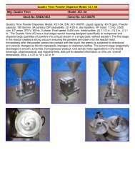
FXV<br />
Single Cell Capacity:<br />
26 – 624 Nominal Tons<br />
78.7 – 1,872 GPM of water at 95 º F/85 º F/78 º F<br />
FXV Closed Circuit Cooling Towers deliver independently verified, fully rated thermal performance over a wide<br />
range of flow and temperature requirements. Standard design features satisfy today’s environmental concerns,<br />
minimize installation costs, maximize year-round operating reliability, and simplify maintenance requirements.<br />
FXV Closed Circuit Cooling Towers<br />
• Low energy consumption<br />
• Low installed cost<br />
• Easy maintenance<br />
• Application flexibility<br />
• Reliable year-round operation<br />
• Long service life<br />
• ASME B31.5 compliant heat transfer coils<br />
• Five-year warranty on mechanical equipment<br />
Baltimore Aircoil Company
E12<br />
Closed Circuit Cooling Towers<br />
...because temperature matters
E13<br />
Benefits<br />
FXV<br />
Low Energy Consumption<br />
• Evaporative cooled equipment minimizes the energy consumption of the entire system because it<br />
provides lower operating temperatures. The owner saves money while conserving natural resources<br />
and reducing environmental impact.<br />
• The FXV provides heat rejection at the lowest possible energy input and maintenance<br />
requirements via:<br />
• High efficiency, low horsepower axial fans<br />
• Closed loop cooling, which minimizes process fouling<br />
• Patented combined flow technology, which reduces evaporation directly off the coil,<br />
minimizing the potential for scaling and fouling (see page E1)<br />
• Variable Frequency Drives (optional) (see page G1 for details)<br />
• ENERGY-MISER ® Fan System (optional) (see page E20 for details)<br />
• BALTIGUARD PLUS TM Fan System (optional) (see page G1 for details)<br />
Low Installed Cost<br />
• Support — All models mount directly on parallel<br />
I-beams and ship complete with motors and drives<br />
factory-installed and aligned.<br />
• Modular Design —Units ship in multiple sections to<br />
minimize the size and weight of the heaviest lift,<br />
allowing for the use of smaller, less costly cranes.<br />
Easy Maintenance<br />
• Access — Hinged access doors on each end wall<br />
and a standard internal walkway provide easy<br />
access to the unit interior.<br />
The unit shown ships in two pieces to<br />
minimize shipping and rigging costs<br />
• Spacious Interior — Provides easy access to the<br />
cold water basin, drift eliminators, fan drive system<br />
and heat transfer coil.<br />
Oversized, hinged access door<br />
Baltimore Aircoil Company
E14<br />
• Access to Spray Distribution — Parallel flow of air and spray<br />
water over the coil allows for inspection and access to the top<br />
of the coil during full operation.<br />
Application Flexibility<br />
• Difficult thermal duties — The combined flow design is ideal for applications requiring a close<br />
approach and/or large range.<br />
• Replacement applications — Single air inlet models are designed to mount directly on existing<br />
support steel of both crossflow and counterflow units.<br />
• Coil configurations — Alternate coil configurations and materials available. ASME “U” Stamp<br />
available (see page E19 for details).<br />
• Highest capacity in the industry — Dual air inlet models offer the highest single cell capacity of<br />
any closed circuit cooling tower in the industry. Projects benefit from fewer required cells, lower<br />
overall fan horsepower, and fewer piping connections.<br />
Reliable Year-Round Operation<br />
• BALTIDRIVE ® Power Train — Backed by a 5-year fan motor and<br />
drive warranty, the BALTIDRIVE ® Power Train utilizes special<br />
corrosion-resistant materials of construction and state-of-the-art<br />
technology to ensure ease of maintenance and reliable<br />
year-round performance.<br />
• Separate Air Inlet Louvers — Reduce the potential for scale build-up<br />
and damaging ice formations at the air/water interface by providing a<br />
line of sight from the outside of the unit into the fill.<br />
Spray distribution system<br />
Closed Circuit Cooling Towers<br />
Long Service Life<br />
Air Inlet louvers<br />
Materials of Construction — Various materials are available to meet the corrosion resistance, unit<br />
operating life, and budgetary requirements of any project (see page E19 for construction options).<br />
...because temperature matters
E15<br />
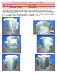
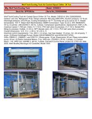
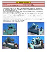
Construction Details<br />
Single Air Inlet Models<br />
FXV<br />
2<br />
3<br />
4<br />
1<br />
7<br />
10<br />
8<br />
9<br />
Baltimore Aircoil Company
E16<br />
1<br />
Heavy-Duty Construction<br />
• G-235 (Z700 metric) hot-dip<br />
galvanized steel panels<br />
2<br />
BALTIDRIVE ® Power Train<br />
• Premium quality, solid-backed,<br />
multi-groove belt<br />
• Corrosion resistant cast aluminum sheaves<br />
• Heavy-duty bearings<br />
(280,000 hour average life)<br />
• Cooling tower duty fan motor<br />
• 5-year motor and<br />
drive warranty<br />
3<br />
Low HP Axial Fan(s)<br />
• High efficiency<br />
• Quiet operation<br />
• Corrosion resistant aluminium<br />
4<br />
Water Distribution System<br />
• Visible and accessible during operation<br />
• Overlapping spray patterns ensure proper<br />
water coverage<br />
• Large orifice, 360˚ non-clog nozzles<br />
5<br />
Coil Section (Not Shown)<br />
• Continuous serpentine, steel tubing<br />
• Hot-dip galvanized after fabrication (HDGAF)<br />
• Pneumatically tested at 375 psig<br />
• Sloped tubes for free drainage of fluid<br />
• ASME B31.5 compliant<br />
• When required, orders shipping into<br />
Canada are supplied with a CRN<br />
6<br />
BACross ® Fill with Integral<br />
Drift Eliminators (Not Shown)<br />
• High efficiency heat transfer surface<br />
• Polyvinyl chloride (PVC)<br />
• Impervious to rot, decay and<br />
biological attack<br />
• Flame spread rating of 5 per<br />
ASTM E84-77a<br />
7<br />
FRP Air Inlet Louvers<br />
• Corrosion resistant<br />
• UV resistant finish<br />
• Maintenance free<br />
8<br />
Cold Water Basin<br />
• Sloped cold water basin for easy cleaning<br />
• Suction strainer with anti-vortex hood<br />
accessible from louver face<br />
• Adjustable water make-up assembly<br />
• Integral internal walkway<br />
9<br />
Recirculating Spray Water<br />
Pump<br />
• Close coupled, bronze fitted<br />
centrifugal pump<br />
• Totally enclosed fan cooled (TEFC) motor<br />
• Bleed line with metering valve installed<br />
from pump discharge to overflow<br />
Hinged Access Doors<br />
10<br />
• Inward swinging door on each end wall<br />
Closed Circuit Cooling Towers<br />
...because temperature matters
E17<br />
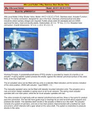
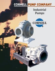
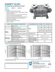
Construction Details<br />
Dual Air Inlet Models<br />
FXV<br />
2<br />
4<br />
3<br />
1<br />
5<br />
7<br />
6<br />
8<br />
9<br />
Baltimore Aircoil Company
E18<br />
1<br />
Heavy-Duty Construction<br />
• G-235 (Z700 metric) hot-dip<br />
galvanized steel frame<br />
2<br />
FRP Casing Panels<br />
• Corrosion resistant<br />
• Maintenance free<br />
• UV resistant finish<br />
3<br />
BALTIDRIVE ® Power Train<br />
• Premium quality, solid backed, multi-groove belt<br />
• Corrosion resistant cast aluminum sheaves<br />
• Heavy-duty bearings (280,000 hour average life)<br />
• Cooling tower duty fan motor<br />
• 5-year motor and drive warranty<br />
4<br />
Low HP Axial Fan<br />
• High efficiency<br />
• Quiet operation<br />
• Corrosion resistant<br />
5<br />
Water Distribution System<br />
• Visible and accessible during operation<br />
• Overlapping spray patterns ensure proper<br />
water coverage<br />
• Large orifice, 360˚ non-clog nozzles<br />
Coil Sections<br />
6<br />
• Continuous serpentine, steel tubing<br />
• Hot-dip galvanized after fabrication (HDGAF)<br />
• Pneumatically tested at 375 psig<br />
• Sloped tubes for free drainage of fluid<br />
• ASME B31.5 compliant<br />
• When required, orders shipping into Canada<br />
are supplied with a CRN<br />
7<br />
BACross ® Fill with Integral Drift<br />
Eliminators<br />
• High efficiency heat transfer surface<br />
• Polyvinyl chloride (PVC)<br />
• Impervious to rot, decay and<br />
biological attack<br />
• Flame spread rating of 5 per ASTM E84-77a<br />
8<br />
FRP Air Inlet Louvers<br />
• Corrosion resistant<br />
• UV resistant finish<br />
• Maintenance free<br />
9<br />
Cold Water Basin<br />
• Sloped cold water basin for easy cleaning<br />
• Suction strainer with anti-vortex hood<br />
• Adjustable water make-up assembly<br />
10<br />
Integral Recirculating Spray<br />
Water Pumps (Not Shown)<br />
• Close coupled, bronze fitted centrifugal pumps<br />
• Totally enclosed fan cooled<br />
(TEFC) motors<br />
• Bleed line with metering valve installed from<br />
pump discharge to overflow<br />
11<br />
Hinged Access Doors<br />
(Not Shown)<br />
• Inward swinging door on each end wall<br />
Closed Circuit Cooling Towers<br />
...because temperature matters
E19<br />
FXV<br />
Custom Features and Options<br />
Construction Options<br />
• Standard Construction:<br />
Models 421 - 661: All steel panels and structural elements are constructed of heavy-gauge G-235<br />
(Z700 metric) hot-dip galvanized steel. Inlet louvers are constructed of UV-resistant, fiberglass<br />
reinforced polyester (FRP).<br />
Models FXV-288 and 364: Casing panels and air inlet louvers are constructed of UV-resistant,<br />
fiberglass reinforced polyester (FRP).<br />
• Optional BALTIBOND ® Corrosion Protection System:<br />
The BALTIBOND ® Corrosion Protection System, a hybrid polymer coating used to extend equipment<br />
life, is applied to all hot-dip galvanized steel components of the closed circuit cooling tower<br />
(excluding heat transfer coil).<br />
• Optional Stainless Steel Cold Water Basin:<br />
A Series 300 stainless steel cold water basin is available. Seams between panels inside the cold<br />
water basin are welded. The basin is leak tested at the factory and welded seams are provided with<br />
a 5-year leak-proof warranty.<br />
• Optional Stainless Steel Construction:<br />
Steel panels and structural elements are constructed of Series 300 stainless steel. Seams between<br />
panels inside the cold water basin are welded. The basin is leak tested at the factory and welded<br />
seams are provided with a five-year leak-proof warranty.<br />
Factory Mutual Approval<br />
All multi-cell units are available with Factory Mutual (FM) Approved construction as an option.<br />
Coil Configurations<br />
• Standard Serpentine Coil:<br />
The standard cooling coil is constructed of continuous lengths of all prime surface steel, hot-dip<br />
galvanized (outside surface) after fabrication (HDGAF). The coil is designed for low pressure drop<br />
with sloping tubes for free drainage of fluid. Each coil is pneumatically tested at 375 psig (2586 kPa)<br />
and is ASME B31.5 compliant.<br />
• Optional Cleanable Header Coil:<br />
The cleanable header tube bundle provides removable cover plates on the inlet and outlet header<br />
boxes to permit access to each serpentine tube circuit for solvent or air-pressure cleaning. Tubes are<br />
all prime surface steel tubing formed into a serpentine shape and welded into an assembly. Coil<br />
material options include carbon steel coils (hot-dip galvanized outside surface) or stainless steel<br />
coils. Each coil is pneumatically tested at 125 psig (860 kPa).<br />
Baltimore Aircoil Company
E20<br />
• Optional Stainless Steel Coil:<br />
Coils are available in Series 300 stainless steel for specialized applications. The coil is designed for<br />
low pressure drop with sloping tubes for free drainage of fluid. Each coil is pneumatically tested at<br />
375 psig (2586 kPa) and is ASME B31.5 compliant.<br />
• Optional Straight-Through Mechanically-Cleanable Coil:<br />
A header box with a removable cover plate at each end of the coil allows access to every tube end for<br />
mechanical cleaning or plugging. It is available in carbon steel (hot-dip galvanized inside and out) or<br />
stainless steel. Each coil is pneumatically tested at 125 psig (860 kPa).<br />
• Optional ASME “U” Stamp Coil:<br />
This serpentine coil is manufactured and tested in accordance with the ASME Boiler and Pressure<br />
Vessel Code, Section VIII, Division 1, and bears the ASME “U” stamp. ASME coils are hot-dip<br />
galvanized (outside surface) after fabrication (HDGAF). The coil is designed for low pressure drop<br />
with sloping tubes for free drainage of fluid. Each coil is pneumatically tested at 375 psig (2586 kPa).<br />
When required, coils shipping into Canada are supplied with a CRN. Other coil configurations are<br />
available for specific applications. Contact your local BAC Representative for details.<br />
Fan Drive System<br />
The fan drive system provides the cooling air necessary to reject unwanted heat from the system to the<br />
atmosphere. The standard fan drive system on all models is the exclusive BALTIDRIVE ® Power Train.<br />
This BAC engineered drive system consists of a specially designed powerband and two cast aluminum<br />
sheaves located on minimum shaft centerline distances to maximize belt life. A cooling tower duty fan<br />
motor, custom engineered for BAC to provide maximum performance for cooling tower service, is<br />
provided and backed by BAC’s comprehensive 5-year motor and fan drive warranty.<br />
ENERGY-MISER ® Fan System<br />
The ENERGY-MISER ® Fan System consists of two standard single-speed fan motor and drive<br />
assemblies. One drive assembly is sized for full speed and load, and the other is sized approximately<br />
2/3 speed and consumes only 1/3 the design horsepower. This configuration allows the system to be<br />
operated like a two-speed motor, but with the reserve capacity of a standby motor in the event of failure.<br />
As a minimum, approximately 70% capacity will be available from the low horsepower motor, even on a<br />
design wet-bulb day. Controls and wiring are the same as those required for a two-speed, two-winding<br />
motor. Significant energy savings are achieved when operating at low speed during periods of reduced<br />
load and/or low wet-bulb temperatures.<br />
Closed Circuit Cooling Towers<br />
BALTIGUARD PLUS TM Fan System<br />
The BALTIGUARD PLUS TM Fan System builds on the advantages of the ENERGY-MISER ® Fan System<br />
by adding a VFD to the smaller motor. Using the VFD on the smaller fan motor, as opposed to the<br />
larger motor, reduces the cost of the VFD, and wiring for the motor. For more information on the<br />
BALTIGUARD PLUS TM Fan System refer to page G1.<br />
...because temperature matters
E21<br />
Custom Features and Options<br />
Independent Fan Operation<br />
FXV<br />
Models FXV-43X, 44X, Q44X, 64X, and Q64X are provided with one fan motor driving two fans as<br />
standard. Models FXV-66X and Q66X are provided with two fan motors driving three fans as standard.<br />
The independent fan option consists of one fan motor and drive assembly for each fan to allow<br />
independent operation, adding an additional step of fan cycling and capacity control.<br />
Gear Drive System,<br />
Close-Coupled Motor<br />
Models FXV-288 and 364 are available<br />
with a close-coupled gear drive system.<br />
Both the gear drive and couplings are<br />
selected with a 2.0 service factor. Gear<br />
construction includes a nickel-alloy steel<br />
shaft, casehardened gears, self<br />
lubrication, and a single piece, gray iron<br />
housing. This drive system ships<br />
completely installed and aligned.<br />
Gear Drive System,<br />
Externally Mounted Motor<br />
Models FXV-288 and 364 are available with<br />
a gear drive system with external TEFC<br />
motor. A non-corrosive carbon-fiber<br />
composite drive shaft with stainless steel<br />
hubs is selected with a 2.0 service factor.<br />
The motor and drive shaft ship separately<br />
for easy field installation.<br />
Gear drive system, close-coupled motor<br />
<strong>Equipment</strong> Controls<br />
BAC control panels are specifically<br />
designed to work seamlessly with all BAC<br />
units and engineered to meet you<br />
particular application. For more on BAC<br />
<strong>Equipment</strong> Controls, see pages G1-G13.<br />
VFD & safety switch<br />
Baltimore Aircoil Company
E22<br />
Low Sound Operation<br />
The low sound levels generated by FXV<br />
Closed Circuit Cooling Towers make<br />
them suitable for installation in most<br />
environments. For very sound sensitive<br />
installations, a low sound fan option is<br />
available to reduce the sound levels<br />
generated from the tower with minimal<br />
impact on thermal performance. The FXV<br />
thermal performance with the low sound<br />
fan has been certified in accordance with<br />
CTI Standard STD-201.<br />
For extremely sound sensitive<br />
installations, factory designed, tested and<br />
rated sound attenuation is available for<br />
both the air intake and discharge.<br />
Whisper Quiet Fans<br />
FXV single air inlet models (FXV-42X through FXV-Q66X) are<br />
available with a “Whisper Quiet” fan that significantly reduces<br />
the sound levels generated from the unit with minimal impact<br />
on thermal performance.<br />
Basinless Unit Construction<br />
(FXV-288 and 364 Models Only)<br />
The basinless unit construction option enables units to be<br />
directly installed on new or existing concrete cold water<br />
basins. This custom feature, reduces maintenance costs by<br />
eliminating the integral basin from traditional units. It<br />
simplifies piping and pumping requirements of multi-cell<br />
installations and provides a cost-effective solution for many<br />
field-erected replacement projects.<br />
Unit with intake and discharge sound attenuation<br />
Closed Circuit Cooling Towers<br />
.<br />
Installation on a concrete basin<br />
...because temperature matters
E23<br />
Accessories<br />
External Service Platforms<br />
FXV<br />
For external service, louver face and access door<br />
platforms can be added to the unit, when purchased<br />
or as an aftermarket item. Safety cages and safety<br />
gates are also available. All components are<br />
designed to meet OSHA requirements.<br />
External platform at louver face<br />
Ladder, Safety Cage, Gate and Handrails (FXV-288 and 364 Models Only)<br />
In the event the end-user elects to provide access to the fan deck, models FXV-288 and 364 can be<br />
furnished with ladders extending from the top of the unit to the base, as well as safety cages, safety<br />
gates, fan deck extensions and handrail packages. All components are designed to meet OSHA<br />
requirements. All access to the top of the equipment must be made in accordance with applicable<br />
government occupational safety standards.<br />
Note: Partial or full grating above the coil air intake is recommended with this option.<br />
Internal Ladder<br />
For access to the motor and drive assemblies on single air inlet models, a moveable internal ladder is<br />
available.<br />
Internal Service Platforms<br />
For access to the motor and drive assemblies on<br />
single air inlet models FXV-L641 through FXV-Q661<br />
and all dual air inlet models, an internal ladder and<br />
upper service platform with handrails is available.<br />
Safety gates are available for all handrail openings.<br />
All components are designed to meet OSHA<br />
requirements.<br />
Vibration Cutout Switch<br />
Internal ladder and service platform<br />
A factory mounted vibration cutout switch is available to effectively protect against equipment failure<br />
due to excessive vibration of the mechanical equipment system. BAC can provide either a mechanical<br />
or solid-state electronic vibration cutout switch in a NEMA 4 enclosure to ensure reliable protection.<br />
Additional contacts can be provided to either switch type to activate an alarm.<br />
Baltimore Aircoil Company
E24<br />
Positive Closure Damper (PCD) Hoods<br />
The FXV’s innovative design results in a low heat loss when the unit is idle. When additional heat loss<br />
prevention is desired, coil air intake hoods with factory mounted PCDs and damper actuators can be<br />
provided. The addition of factory mounted insulation to the hood and casing further reduces the heat<br />
loss by minimizing losses due to conduction. See page E29 for heat loss data on all FXV models.<br />
Basin Heaters<br />
Closed circuit cooling towers exposed to below<br />
freezing ambient temperatures require protection<br />
to prevent freezing of the water in the cold water<br />
basin when the unit is idle. Factory-installed<br />
electric immersion heaters, which maintain +40°F<br />
(4.4°C) water temperature, are a simple and<br />
inexpensive way of providing such protection.<br />
Heater Sizing Data<br />
Model Numbers<br />
0˚F (-17.8˚C) Ambient Heaters<br />
Electric Water Level Control Package<br />
The electric water level control replaces the standard mechanical<br />
make-up valve when a more precise water level control is<br />
required. This package consists of a conductance-actuated level<br />
control mounted in the basin and a solenoid activated valve in the<br />
make-up water line. The valve is slow closing to minimize<br />
water hammer.<br />
Basin heater<br />
-20˚F (-28.9˚C) Ambient Heaters<br />
Number of Heaters kW per Heater Number of Heaters kW per Heater<br />
FXV - 42X 1 4 1 6<br />
FXV - 43X 1 6 1 8<br />
FXV - 44X 1 8 1 12<br />
FXV - 64X 1 12 1 16<br />
FXV - 66X 1 16 1 21<br />
FXV - 288 2 12 2 15<br />
FXV - 364 2 14 2 20<br />
Closed Circuit Cooling Towers<br />
Electric water level<br />
control package<br />
...because temperature matters
E25<br />
Accessories<br />
Extended Lubrication Lines<br />
FXV<br />
Extended lubrication lines are available for<br />
lubrication of the fan shaft bearings. Grease fittings<br />
are located inside the plenum area next to the<br />
access door.<br />
Grease fittings at the access door & bearings with the extended lubrication line option<br />
High Temperature Fill<br />
Optional high temperature fill material is available for high entering fluid temperatures.<br />
Air Inlet Screens<br />
Wire mesh screens can be factory-installed over the inlet<br />
louvers and the spray distribution system to prevent debris<br />
from entering the unit.<br />
Basin Sweeper Piping<br />
Basin sweeper piping provides an effective method of<br />
preventing debris from collecting in the cold water basin of the<br />
tower. A complete piping system, including nozzles, is provided<br />
in the tower basin for connection to side stream filtration<br />
equipment (by others). For more information on filtration<br />
systems , see page M159.<br />
Basin sweeper piping<br />
Baltimore Aircoil Company
Structural Support<br />
E26<br />
The recommended support arrangement for FXV Closed Circuit Cooling Towers consists of parallel<br />
I-beams positioned as shown on the drawings. Besides providing adequate support, the steel also<br />
serves to raise the unit above any solid foundation to assure access to the bottom of the tower.<br />
Alternate steel support designs include a cantilevered plan as indicated by the optional minimum “D”<br />
dimension in the table below. To support an FXV on columns or in an alternate arrangement not shown<br />
here, consult your local BAC Representative.<br />
Single Air Inlet<br />
Dual Air Inlet<br />
Model Number<br />
D<br />
Optional Minimum<br />
D*<br />
Maximum<br />
Deflection<br />
FXV - 42x 8’ 3” 5’ 9” 3/16”<br />
FXV - 43x 8’ 3” 5’ 9” 5/16”<br />
FXV - 44x 8’ 3” 5’ 9” 3/8”<br />
FXV - 64x 11’ 7-3/4” 8’ 0” 3/8”<br />
FXV - 66x 11’ 7-3/4” 8’ 0” 1/2”<br />
*When unit is supported with a cantilever plan, the side<br />
opposite the air inlet shall be cantilevered.<br />
Model<br />
Number<br />
D<br />
Max.<br />
Deflection<br />
FXV-288-xxx 23’ 9-1/8” 1/2”<br />
FXV-364-xxx 26’ 5/8” 1/2”<br />
Closed Circuit Cooling Towers<br />
Notes:<br />
1. Support steel and anchor bolts to be designed and furnished<br />
by others.<br />
2. All support steel must be level at the top.<br />
3. Beams must be selected in accordance with accepted structural<br />
practice. Maximum deflection of beam under unit to be 1/360<br />
of span, not to exceed 1/2 inch.<br />
4. If vibration isolation rails are to be used between the unit and<br />
supporting steel, be certain to allow for the length of the vibration<br />
rails when determining the length of the supporting steel, as<br />
vibration rail length and mounting hole locations may differ from<br />
those of the unit.<br />
5. If point vibration isolation is used with multi-cell units, the isolators<br />
must be located under the support steel, not between the support<br />
steel and the closed circuit cooling towers.<br />
...because temperature matters
E27<br />
Engineering Data<br />
Do not use for construction. Refer to factory certified dimensions. This handbook includes data current<br />
at the time of publication, which should be reconfirmed at the time of purchase. Up-to-date engineering<br />
data, free <strong>product</strong> selection software, and more can be found at www.BaltimoreAircoil.com.<br />
Single Air Inlet Models<br />
FXV<br />
3" OVERFLOW<br />
2" DRAIN<br />
Model<br />
Number<br />
Notes:<br />
Motor HP Weights (lbs) Dimensions Connection Sizes 2,3 Spray<br />
Nominal<br />
Heaviest<br />
Make-Up<br />
Pump<br />
Tons 5 Fan Pump Operating 1 Shipping<br />
L W H A P<br />
Coil<br />
Section<br />
Water<br />
(GPM)<br />
FXV-421 33<br />
7,730 5,050 2,900<br />
FXV-422 46 8,190 5,370 3,220 60<br />
3 to 10 1.5<br />
6’ 1-1/4” 8’ 5-1/4” 13’ 2-3/4” 6’ 3/4” 1’ 3-3/4” 1/2” 4” 190<br />
FXV-423 52 8,680 5,710 3,560 74<br />
FXV-424 59 9,160 6,050 3,900 88<br />
FXV-431 57<br />
11,230 7,160 4,240<br />
69<br />
FXV-432 73 11,930 7,650 4,730 90<br />
5 to 15 2<br />
9’ 1-1/4” 8’ 5-1/4” 13’ 2-3/4” 6’ 3/4” 1’ 4-1/4” 1/2” 4” 290<br />
FXV-433 81 12,630 8,140 5,220 112<br />
FXV-434 95 13,380 8,680 5,760 133<br />
FXV-441 92<br />
14,200 8,760 5,120<br />
91<br />
FXV-442 111 15,150 9,410 5,770 120<br />
1/2” 4”<br />
FXV-443 122 16,080 10,060 6,420 149<br />
FXV-444 140<br />
7.5 to 20 3<br />
17,070 10,770 7,130<br />
12’ 1-1/4” 8’ 5-1/4” 13’ 2-3/4” 6’ 3/4” 1’ 8-1/4”<br />
500<br />
178<br />
FXV-Q440 88 15,150 9,410 5,770<br />
124<br />
1/2’ 6”<br />
FXV-Q441 125 17,070 10,770 7,130 182<br />
FXV-641 144<br />
18,560 10,890 6,730<br />
146<br />
FXV-642 175 20,050 11,930 7,770 192<br />
1” 4”<br />
FXV-643 193 21,550 12,980 8,820 238<br />
10 to 30 5<br />
12’ 1-1/4” 11’ 10” 15’ 10-3/4” 8’ 8-3/4” 1’ 8-3/4”<br />
715<br />
FXV-644 215 23,050 14,040 9,880 284<br />
FXV-Q640 134 20,050 11,930 7,770<br />
194<br />
1” 6”<br />
FXV-Q641 186 23,050 14,040 9, 880 286<br />
FXV-661 231<br />
27,070 15,510 9,690<br />
218<br />
FXV-662 267 29,290 17,070 11,250 288<br />
1” 4”<br />
FXV-663 295 31,570 18,670 12,850 358<br />
15 to 45 7.5<br />
18’ 1-1/4” 11’ 10” 16’ 4-1/4” 9’ 2-1/4” 2’ 3/8”<br />
900<br />
FXV-664 331 33,810 20,280 14,460 429<br />
FXV-Q660 215 29,290 17,070 11,250<br />
299<br />
1” 8”<br />
FXV-Q661 299 33,810 20,280 14,460 439<br />
1. Operating weight is for the tower with the water level in the cold<br />
water basin at the overflow.<br />
2. The actual size of the inlet and outlet connection may vary with<br />
the design flow rate. Consult unit print for dimensions.<br />
Internal<br />
Coil<br />
Volume<br />
(GAL)<br />
46<br />
3. Inlet and outlet connections are beveled for welding.<br />
4. Standard make-up, drain and overflow connections are MPT.<br />
5. Nominal tons of cooling represents 3 GPM of water from 95ºF to<br />
85ºF at a 78ºF entering wet-bulb temperature.<br />
Baltimore Aircoil Company
E28<br />
See page E81<br />
for Engineering<br />
Considerations.<br />
Dual Air Inlet Models<br />
Model Number<br />
Notes:<br />
1. Operating weight is for the tower with the water level in the cold<br />
water basin at the overflow.<br />
2. The actual size of the inlet and outlet connection may vary with<br />
the design flow rate. Consult unit print for dimensions.<br />
3. Inlet and outlet connections are beveled for welding.<br />
4. Standard make-up, drain and overflow connections are located<br />
on the bottom of the unit. Make-up connection is 1-1/2” MPT<br />
standpipe, drain is 2” FPT and overflow is 3” FPT.<br />
6" FLUID OUT<br />
6" FLUID IN<br />
Motor HP Weights (lbs) Dimensions<br />
Nominal<br />
Heaviest<br />
Tons 6 Fan Pump Operating 1 Shipping<br />
L W H<br />
Section<br />
Spray<br />
Pump<br />
(GPM)<br />
5. Models shipped with an optional gear drive or low sound fan<br />
may have heights up to 10.5" greater than shown.<br />
Internal Coil<br />
Volume<br />
(GAL)<br />
FXV-288-31x 468<br />
46,470 28,150 8,050<br />
600<br />
FXV-288-41x 502 20 to 60 15 50,160 30,910 9,430 11’ 11” 24’ 1/2” 18’ 10-3/8” 1,720 712<br />
FXV-288-1Qx 439 50,160 30,910 9,430 706<br />
FXV-364-31x 579<br />
54,440 32,170 9,390<br />
696<br />
FXV-364-41x 624 25 to 75 15 58,800 35,450 11,030 13’ 11-1/8” 26’ 3-1/2” 19’ 0-3/8” 1,720 828<br />
FXV-364-1Qx 550 58,800 35,450 11,030 862<br />
6. Nominal tons of cooling represents 3 GPM of water from 95ºF to<br />
85ºF at a 78ºF entering wet-bulb temperature.<br />
Closed Circuit Cooling Towers<br />
...because temperature matters
E29<br />
Engineering Data:<br />
Cold Weather Operation<br />
FXV Heat Loss Data (BTUH)<br />
Model<br />
Number<br />
Standard<br />
Unit<br />
Unit w/<br />
PCD Hood<br />
Unit w/ PCD<br />
Hood & Insulation<br />
FXV<br />
FXV-421<br />
FXV-422<br />
FXV-423<br />
FXV-424<br />
FXV-431<br />
FXV-432<br />
FXV-433<br />
FXV-434<br />
68,400<br />
87,100<br />
105,200<br />
122,400<br />
102,800<br />
131,200<br />
158,000<br />
183,000<br />
43,500<br />
47,100<br />
50,500<br />
54,000<br />
60,800<br />
65,600<br />
70,600<br />
74,900<br />
30,100<br />
32,300<br />
34,700<br />
37,000<br />
43,200<br />
46,500<br />
49,600<br />
52,800<br />
FXV-441<br />
FXV-442<br />
FXV-443<br />
FXV-444<br />
FXV-Q440<br />
FXV-Q441<br />
135,700<br />
172,900<br />
208,000<br />
241,000<br />
172,900<br />
241,000<br />
76,700<br />
82,100<br />
87,600<br />
92,900<br />
82,100<br />
92,900<br />
55,200<br />
59,100<br />
62,900<br />
66,500<br />
59,100<br />
66,500<br />
FXV-641<br />
FXV-642<br />
FXV-643<br />
FXV-644<br />
FXV-Q640<br />
FXV-Q641<br />
203,400<br />
259,800<br />
313,100<br />
362,900<br />
259,800<br />
362,900<br />
103,800<br />
109,700<br />
115,600<br />
121,300<br />
109,700<br />
121,300<br />
75,300<br />
79,300<br />
83,200<br />
86,900<br />
79,300<br />
86,900<br />
FXV-661<br />
FXV-662<br />
FXV-663<br />
FXV-664<br />
FXV-Q660<br />
FXV-Q661<br />
304,500<br />
387,500<br />
404,700<br />
536,900<br />
387,500<br />
536,900<br />
158,200<br />
165,500<br />
172,400<br />
179,100<br />
165,500<br />
179,100<br />
118,000<br />
123,000<br />
127,600<br />
132,200<br />
123,000<br />
132,200<br />
FXV-288-31x<br />
FXV-288-41x<br />
FXV-288-1Qx<br />
760,200<br />
881,100<br />
881,100<br />
280,700<br />
294,500<br />
294,500<br />
202,000<br />
211,000<br />
211,000<br />
FXV-364-31x<br />
FXV-364-41x<br />
FXV-364-1Qx<br />
894,000<br />
1,036,200<br />
1,036,200<br />
330,100<br />
346,400<br />
346,400<br />
237,600<br />
248,100<br />
248,100<br />
Notes:<br />
1 Heat loss based on 50ºF entering coil water and -10ºF ambient<br />
with 45 MPH wind (fans and pump off).<br />
2. One inch thick PVC nitrite rubber blend thermal insulation on both<br />
the PCD hood and the casing panels surrounding the coil.<br />
Dimensional Data of Positive Closure Damper Hood<br />
Model<br />
Number<br />
Hood Ship.<br />
Weight (lbs.)<br />
Operating Weight Add<br />
(lbs.)<br />
Length<br />
(L)<br />
Width (W)<br />
Hood Height<br />
(Y)<br />
Unit Height<br />
(H)<br />
FXV-42x 390 320 5’ 11-7/8” 3’ 5-1/4” 2’ 5-1/8” 15’ 1-3/4”<br />
FXV-43x 540 430 8’ 11-7/8” 3’ 5-1/4” 2’ 5-1/8” 15’ 1-3/4”<br />
FXV-44x 720 570 11’ 11-7/8” 3’ 5-1/4” 2’ 5-1/8” 15’ 1-3/4”<br />
FXV-64x 1,160 920 11’ 11-7/8” 5’ 3-1/2” 2’ 5-1/8” 17’ 9-3/4”<br />
FXV-66x 1,650 1,300 17’ 11-7/8” 5’ 3-1/2” 2’ 5-1/8” 17’ 9-3/4”<br />
FXV-288-xxx 1,300 1,040 11’ 11” 6’ 3-3/8” 2’ 5-1/8” 20’ 2-5/8”<br />
FXV-364-xxx 1,500 1,200 13’ 11-1/8” 6’ 3-3/8” 2’ 5-1/8” 20’ 2-5/8”<br />
Notes:<br />
1. Hood shipping weight<br />
includes shipping skid<br />
weight.<br />
Baltimore Aircoil Company
Engineering Specifications<br />
See our website at www.BaltimoreAircoil.com for an electronic copy of <strong>product</strong> engineering specifications.<br />
1.0 Closed Circuit Cooling Tower<br />
1.1 General: Furnish and install, as shown on the plans,<br />
___ factory-assembled closed circuit cooling tower(s) of<br />
induced draft design with vertical air discharge. Overall<br />
dimensions shall not exceed approximately ___ ft (mm) x<br />
___ ft (mm), with an overall height not exceeding approximately<br />
___ ft (mm). Operating weight shall not exceed<br />
_____ lbs (kg). The closed circuit cooling tower shall be<br />
Baltimore Aircoil Company Model FXV-___.<br />
1.2 Thermal Capacity (water as heat transfer fluid): The<br />
closed circuit cooling tower shall be warranted by the manufacturer<br />
to have capacity to cool _______ USGPM (l/s) of<br />
water from ______°F (°C) to _____°F (°C) at _____°F (°C)<br />
entering wet-bulb temperature. Coil pressure drop shall not<br />
exceed ________ psi (kPa). The performance shall be<br />
certified by the Cooling Technology Institute in accordance<br />
with CTI Certification Standard STD-201 or, lacking such<br />
certification, a field<br />
acceptance test shall be conducted within the warranty<br />
period in accordance with CTI Acceptance Test Code ATC-<br />
105, by the Cooling Technology Institute, or other qualified<br />
independent third party testing agency. Manufacturers'<br />
performance guarantees or performance bonds without CTI<br />
Certification of water ratings shall not be accepted.<br />
(Alternate) 1.2 Thermal Capacity (aqueous glycol solution<br />
as heat transfer fluid): The closed circuit cooling tower(s)<br />
shall be warranted by the manufacturer to cool<br />
________USGPM (l/s) of _____% by volume<br />
ethylene/propylene glycol solution from ______°F (°C) to<br />
_____°F (°C) at _____°F (°C) entering wet-bulb temperature.<br />
Coil pressure drop shall not exceed ________ psi<br />
(kPa). Basis for thermal performance rating shall be the<br />
Cooling Technology Institute (CTI) certified rating for water<br />
cooling appropriately adjusted for the thermal properties of<br />
the aqueous glycol solution used. Additionally, the thermal<br />
performance of the <strong>product</strong> line with water as the heat<br />
transfer fluid shall be certified by the CTI in accordance<br />
with CTI Certification Standard STD-201. Manufacturers'<br />
performance guarantees or performance bonds without CTI<br />
Certification of water ratings shall not be accepted.<br />
1.3 Quality Assurance: The cooling tower manufacturer<br />
shall have a Management System certified by an accredited<br />
registrar as complying with the requirements of ISO-<br />
9001:2000 to ensure consistent quality of <strong>product</strong>s and<br />
services.<br />
2.0 Construction Details<br />
2.1 Corrosion Resistant Construction (standard): Unless<br />
otherwise noted in this specification, all steel panels and<br />
structural elements shall be constructed from heavy-gauge,<br />
G-235 (Z700 metric) hot-dip galvanized steel, with cut<br />
edges given a protective coat of zinc-rich compound.<br />
(Alternate) 2.1 Corrosion Resistant Construction: Unless<br />
otherwise noted in this specification, all steel panels and<br />
structural members shall be protected with the<br />
BALTIBOND ® Corrosion Protection System. The system<br />
shall consist of G-235 (Z700 metric) hot-dip galvanized<br />
steel prepared in a four-step (clean, pre-treat, rinse, dry)<br />
process with an electrostatically sprayed, thermosetting,<br />
hybrid polymer fuse-bonded to the substrate during a thermally<br />
activated curing stage and monitored by a 23-step<br />
quality assurance program. Coatings other than the<br />
BALTIBOND ® Corrosion Protection System must be<br />
submitted to the engineer for pre-approval. Approved<br />
equals must have undergone testing, resulting in the<br />
following results as a minimum:<br />
1. When X-scribed to the steel substrate it shall be able<br />
to withstand 6000 hours of 5% salt spray per ASTM<br />
B117 without blistering, chipping, or loss of adhesion;<br />
2. When X-scribed to the steel substrate it shall be able to<br />
withstand 6000 hours of exposure to acidic (pH=4.0)<br />
and alkaline (pH=11.0)water solutions at 95ºF (35˚C)<br />
without signs of chemical attack;<br />
3. Shall withstand impact of 160 in-lbs per ASTM D2794<br />
without fracture or delamination of the polymer layer;<br />
4. Shall withstand 6000 hours of ultraviolet radiation<br />
equivalent to 120,000 hours of noontime sun exposure<br />
without loss of functional properties;<br />
5. Shall withstand 200 thermal shock cycles between -<br />
25ºF and +180ºF (-32˚C and 82˚C) without loss of<br />
adhesion or other deterioration;<br />
6. Shall withstand 6000 hours of exposure to 60 psi<br />
(42,184 kg/m 2 ) water jet without signs of wear or<br />
erosion.<br />
(Alternate) 2.1 Optional Stainless Steel Construction: All<br />
steel panels and structural elements shall be constructed<br />
from heavy-gauge, Series 300 stainless steel.<br />
2.2 Coil Section: The heat transfer section of the closed<br />
circuit cooling tower shall be encased with removable<br />
heavy-gauge galvanized steel panels (or corrosion<br />
resistant, fiberglass reinforced polyester (FRP) on Models<br />
FXV-288 to 364). The coil shall be constructed of continuous<br />
serpentine all prime surface steel, be pneumatically<br />
tested at 375 psig (2,685 kPa), and be hot-dip galvanized<br />
after fabrication. The coil shall be designed for free<br />
drainage of fluid and shall be ASME B31.5 compliant.<br />
Maximum allowable working pressure shall be 300 psig<br />
(280 psig for coils supplied with a CRN).<br />
(Alternate) 2.2 Optional Cleanable Header Coil: Coil(s) to<br />
be constructed of continuous serpentine prime surface carbon<br />
steel, with a hot-dip galvanized (after fabrication) outside<br />
surface. Inlet and outlet headers have removable<br />
cover plates, and elbowed fluid inlet and outlet connections<br />
to allow removal of the cover plates without disturbing fluid<br />
piping. Coil(s) shall be pneumatically tested at 125 psig<br />
(895 kPa).<br />
(Alternate) 2.2 Optional Cleanable Tube Coil: Coil(s) to be<br />
constructed with straight full-length tubes, pitched in the<br />
direction of fluid flow for free drainage, and pneumatically<br />
tested at 125 psig (895 kPa). Full-height box headers and<br />
removable cover plates allow access to all tubes at both<br />
ends. The entire assembly is hot-dip galvanized after<br />
fabrication, inside and out.<br />
(Alternate) 2.2 Optional ASME Coil: Coil(s) shall be<br />
designed and constructed to meet the requirements of<br />
ASME Boiler and Pressure Vessel Code, Section VIII,<br />
Division 1, and bear the U stamp.<br />
E30<br />
Closed Circuit Cooling Towers<br />
...because temperature matters
E31<br />
FXV<br />
(Alternate) 2.2 Optional Stainless Steel Coil: Coil(s) shall<br />
be constructed of Series 300 stainless steel serpentine<br />
tube. Tubes shall be sloped for free drainage and coil<br />
assembly shall be pneumatically tested at 375 psig (2,685<br />
kPa). Coil(s) shall be ASME B31.5 compliant.<br />
2.3 Cold Water Basin: The cold water basin shall be<br />
constructed of heavy-gauge hot-dip galvanized steel. The<br />
basin shall include a depressed section with drain/<br />
clean-out connection. Standard accessories shall include<br />
large area, lift-out steel strainers with perforated openings<br />
sized smaller than water distribution nozzle orifices, an<br />
integral anti-vortexing hood to prevent air entrainment,<br />
waste water bleed line, and brass make-up valve with<br />
large diameter plastic float arranged for easy adjustment.<br />
(Alternate) 2.3 Optional Stainless Steel Cold Water Basin:<br />
The cold water basin shall be made of Series 300<br />
stainless steel. All factory seams in the cold water basin<br />
shall be welded, leak tested at the factory to ensure<br />
watertight assembly and shall be warranted against leaks<br />
for 5 years.<br />
2.4 Casing Panels: Models FXV-4xx, 6xx, Lxxx, & Qxxx:<br />
Casing panels shall be constructed of steel matching the<br />
structure defined in section 2.1.<br />
Or, for Models FXV-288 and 364:<br />
Casing panels shall be constructed of corrosion resistant,<br />
fiberglass reinforced polyester (FRP).<br />
3.0 Spray Water System<br />
3.1 Spray Water Pump(s): The closed circuit cooling<br />
tower shall include an appropriate number of closecoupled,<br />
bronze-fitted centrifugal pump and motor<br />
assemblies equipped with mechanical seal, mounted in<br />
the basin and piped from the suction connection to the<br />
water distribution system. The pump motor(s) shall be the<br />
totally enclosed fan cooled (TEFC) type suitable for<br />
_____ volts, ___ phase, and ____ hertz electrical service.<br />
The system shall include a metering valve and bleed line<br />
to control the bleed rate from the pump discharge to the<br />
overflow connection.<br />
3.2 Water Distribution System: Water shall be distributed<br />
evenly over the coil at a flow rate sufficient to ensure<br />
complete wetting of the coil at all times. Large diameter,<br />
non-clog, 360° plastic distribution nozzles shall utilize a<br />
two stage diffusion pattern to provide overlapping,<br />
umbrella spray patterns that create multiple intersection<br />
points with adjacent nozzles. The branches and spray<br />
nozzles shall be held in place by snap-in rubber<br />
grommets, allowing quick removal of individual nozzles<br />
or complete branches for cleaning or flushing.<br />
manufactured and performance tested by the closed circuit<br />
cooling tower manufacturer to provide single source<br />
responsibility and assure control of the final <strong>product</strong>. A<br />
separate set of drift eliminators shall be removable in<br />
easily handled sections for quick access to the coil.<br />
Eliminators shall have a minimum of three changes in air<br />
direction.<br />
(Alternate) 4.1 Fill and Drift Eliminators: The high<br />
temperature fill and integral drift eliminators shall be<br />
formed from self-extinguishing (per ASTM-568) polyvinyl<br />
chloride (PVC) having a flame spread rating of 5 per<br />
ASTM E84 and shall be impervious to rot, decay, fungus<br />
and biological attack. The high temperature fill shall be<br />
suitable for entering water temperatures up to 140°F<br />
(60.0˚C). The fill shall be manufactured, tested and rated<br />
by the cooling tower manufacturer and shall be elevated<br />
above the cold water basin to facilitate cleaning.<br />
5.0 Air Inlet Louvers<br />
5.1 Air Inlet Louvers: Air inlet louvers shall be<br />
wave-formed, fiberglass-reinforced polyester (FRP),<br />
spaced to minimize air resistance and prevent water<br />
splash-out.<br />
6.0 Mechanical <strong>Equipment</strong><br />
6.1 Fan(s): Fan(s) shall be heavy-duty, axial flow, with<br />
aluminum alloy blades. Air shall discharge through a fan<br />
cylinder designed for streamlined air entry and minimum<br />
fan blade tip clearance for maximum fan efficiency. Fan(s)<br />
and shaft(s) shall be supported by heavy-duty, selfaligning,<br />
grease-packed ball bearings with moisture-proof<br />
seals and integral slinger rings, designed for minimum L 10<br />
life of 40,000 hours. Fan(s) shall be drive by a one-piece,<br />
multi-groove neoprene/polyester belt designed specifically<br />
for evaporative cooling service. Fan and motor sheave(s)<br />
shall be fabricated from cast aluminum.<br />
6.2 Fan Motor: Fan motor(s) shall be totally enclosed air<br />
over (TEAO), reversible, squirrel cage, ball bearing type<br />
with 1.15 service factor, designed specifically for<br />
evaporative cooling duty on _____ volt/ ___ hertz/ ___<br />
phase electrical service. The motor shall be furnished<br />
with special moisture protection on windings, shafts, and<br />
bearings. Each motor shall be mounted on an easily<br />
adjusted, heavy-duty motor base.<br />
(Alternate) 6.2 Fan Motor: Fan motor(s) shall be totally<br />
enclosed air over (TEAO), reversible, squirrel cage, ball<br />
bearing type designed specifically for evaporative cooling<br />
duty on ____ volt/ ___ hertz/ ____ phase electrical<br />
service. The motor shall be furnished with special<br />
moisture protection on windings, shafts, and bearings.<br />
Fan motors shall be inverter duty type designed per<br />
NEMA Standard MG1, Section IV, Part 31.<br />
4.0 Fill and Drift Eliminators<br />
4.1 Fill and Drift Eliminators: The fill and integral drift<br />
eliminators shall be formed from self-extinquishing (per<br />
ASTM-568) polyvinyl chloride (PVC) having a flame<br />
spread rating of 5 per ASTM E84 and shall be impervious<br />
to rot, decay, fungus and biological attack. The fill shall be<br />
6.3 Mechanical <strong>Equipment</strong> Warranty: The fan(s), fan<br />
shaft(s), sheaves, bearings, mechanical equipment<br />
support and fan motor shall be warranted against defects<br />
in materials and workmanship for a period of five (5)<br />
years from date of shipment.<br />
Baltimore Aircoil Company
E32<br />
6.4 ENERGY-MISER ® Fan System (optional): Two singlespeed<br />
fan motors, one sized for full speed and load, the<br />
other sized for 2/3 speed and approximately 1/3 the full<br />
load horsepower, shall be provided for capacity control<br />
and stand-by protection from drive or motor failure.<br />
Two-speed motor(s) are not an acceptable alternative.<br />
(Alternate) 3.4 BALTIGUARD PLUS TM Fan System: Two<br />
single speed fan motors, one sized for load, the other<br />
sized for 1/3 of the full load horsepower shall be provided<br />
in each cell for capacity control and standby protection<br />
from drive or motor failure. The manufacturer of the<br />
equipment shall supply controls for the larger motor, a<br />
VFD for the smaller motor and factory programmed logic<br />
controller to maximize energy saving for off peak load and<br />
wet-bulb conditions.<br />
7.0 Access<br />
7.1 Plenum Access: A large, hinged access door shall be<br />
provided on each end wall for access to the coil, drift<br />
eliminators, and fan plenum section. The water make-up<br />
valve, float ball, and suction strainer shall be easily<br />
accessible. On single side air inlet units, the access door<br />
shall open to an internal walkway.<br />
8.0 Sound<br />
8.1 Sound Level: To maintain the quality of the local<br />
environment, the maximum sound pressure levels (dB)<br />
measured 50 ft (15,240 mm) from the closed circuit<br />
cooling tower operating at full fan speed shall not exceed<br />
the sound levels detailed below.<br />
(Alternate) 8.1 Sound Level: To maintain the quality of the<br />
local environment, the closed circuit cooling tower shall be<br />
furnished with a low sound fan. The thermal performance<br />
of the closed circuit cooling tower shall be certified by the<br />
Cooling Technology Institute in accordance with paragraph<br />
1.2 of this specification when furnished with the low sound<br />
fan. Maximum sound pressure levels (dB) measured 50 ft<br />
(15,240 mm) from the closed circuit cooling tower<br />
operating at full fan speed shall not exceed the sound<br />
levels detailed below.<br />
Location 63 125 250 500 1000 2000 4000 8000 dB(A)<br />
Discharge<br />
Air Inlet<br />
Cased Face<br />
9.0 Accessories<br />
9.1 Vibration Isolation Rails (Available on single air inlet<br />
models only): Spring-type vibration isolation rails,<br />
constructed of steel channels and base plates, painted<br />
with a rust-resistant primer shall be provided to minimize<br />
vibration transmission from the tower to the building<br />
structure. The isolators shall be designed for a static<br />
deflection of 1" (25.4 mm) and a maximum wind speed<br />
of 50 mph (80 km/h).<br />
(Alternate) 9.1 Vibration Isolation Rails (Available on single<br />
air inlet models only): Spring-type vibration isolation rails,<br />
constructed of steel channels and base plates, coated with<br />
a 0.003" (.076 mm) layer of zinc after fabrication shall be<br />
provided to minimize vibration transmission from the tower<br />
to the building structure. The isolators shall be designed<br />
for a static deflection of 1" (25.4 mm) and a maximum<br />
wind speed of 50 mph (80 km/h).<br />
9.2 Basin Heater(s): The cooling tower cold water basin<br />
shall be provided with electric heater(s) to prevent freezing<br />
in low ambient conditions. The heater(s) shall be selected<br />
to maintain 40°F (4.4˚C) pan water temperatures at ____°<br />
F(˚C) ambient. The heater(s) shall be______V/ ____<br />
phase/___Hz electric and shall be provided with low water<br />
cutout and thermostat.<br />
(Alternate) 9.2 Basin Heaters (Available on single air inlet<br />
models only): A steam coil shall be factory installed in the<br />
cooling tower depressed sump of the cold water basin to<br />
prevent freezing during cold water shutdown. The steam<br />
coil shall be capable of maintaining 40°F (4.4˚C) pan water<br />
temperature at a –20°F (-28.9˚C) ambient temperature<br />
given 5 psig (34 kPa) at the coil inlet connection.<br />
9.3 Basin Water Level Control: The cooling tower<br />
manufacturer shall provide an electric water level control<br />
(EWLC) system. The system shall consist of water level<br />
sensing and control units in quantities and locations as<br />
indicated on the drawings. Each water level sensing and<br />
control unit shall consist of the following: NEMA 4<br />
enclosure with gasketed access cover; solid state controls<br />
including all necessary relays and contacts to achieve the<br />
specified sequence of operation; stainless steel water level<br />
sensing electrodes with brass holder; Schedule 40 PVC<br />
standpipe assembly with vent holes, and all necessary<br />
stainless steel mounting hardware. Provide PVC union<br />
directly below the control enclosure to facilitate the<br />
removal and access of electrodes and control enclosure.<br />
The number and position of water level sensing electrodes<br />
shall be provided to sense the following: high water level,<br />
low water level, high water alarm level, low water alarm,<br />
and heater safety cutout.<br />
9.4 Vibration Cutout Switch: Provide mechanical local<br />
reset vibration switch. The mechanical vibration cutout<br />
switch will be guaranteed to trip at a point so as not to<br />
cause damage to the cooling tower. To ensure this, the<br />
trip point will be a frequency range of 0 to 3,600 RPM and<br />
a trip point of 0.2 to 2.0 g’s.<br />
(Alternate) 9.4 Vibration Cutout Switch: Provide electronic<br />
remote reset vibration switch with contact for BAS<br />
monitoring. Wiring shall be by the installing contractor.<br />
The electronic vibration cut out switch shall be set to trip at<br />
a point so as not to cause damage to the cooling tower.<br />
The trip point will be 0.45 in/sec (0.0114 m/sec).<br />
9.5 Basin Sweeper Piping: The cold water basin of the<br />
cooling tower shall be equipped with PVC sump sweeper<br />
piping for a separator (supplied by others).<br />
9.6 Intake Sound Attenuation: The unit shall be equipped<br />
with intake sound attenuators consisting of fiberglass<br />
acoustical baffles encased in steel to further reduce sound<br />
levels.<br />
Closed Circuit Cooling Towers<br />
...because temperature matters
E33<br />
FXV<br />
9.7 Sound Attenuation: The unit shall be equipped with a<br />
straight hood lined with sound absorbing fiberglass<br />
acoustical baffles to reduce sound levels from the top of<br />
the unit.<br />
9.8 Heat loss: The heat loss for the FXV shall be equal<br />
to or less than __________ BTUH using either a<br />
standard unit, a unit with a hood, positive closure<br />
dampers, insulation or a combination.<br />
9.9 External platform with ladder: A galvanized steel<br />
platform and aluminum ladder to grade shall be provided<br />
at all access doors to access the plenum section of the<br />
cooling tower. All working surfaces shall be able to<br />
withstand 50 psf live load or 200 pound concentrated<br />
load.a<br />
(Alternate for Dual air inlet FXVs only) 9.9 Ladder: An<br />
aluminum ladder (with galvanized steel safety cage) shall<br />
be provided for access to the fan deck. Access door or<br />
service platforms shall not be accepted as equal.<br />
(Alternate for Dual air inlet FXVs only) 9.9 Handrails:<br />
1-1/4" galvanized steel pipe handrail shall be proved<br />
around the perimeter of the cooling tower cells. The<br />
handrails shall be provided with knee and toe rails and<br />
shall conform to the requirements of OSHA.<br />
9.10 Internal Walkway for Dual Air inlet FXV: An internal<br />
walkway shall be provided in the plenum section to<br />
provide for inspection and maintenance. All working<br />
surfaces shall be able to withstand 50 psf (244 Kg/m 2 )live<br />
load or 200 pound (90.7 Kg) concentrated load. Other<br />
components of the cooling tower, i.e. basin and fill/drift<br />
eliminators, shall not be considered an internal working<br />
surface. Manufacturers that require that these surfaces be<br />
used as a working platform shall provide a two-year<br />
extended warranty to the Owner to repair any damage to<br />
these surfaces caused by routine maintenance.<br />
9.11 Internal Platform: An internal platform shall be<br />
provided in the plenum section to provide for inspection<br />
and maintenance. All working surfaces shall be able to<br />
withstand 50 psf live load or 200 pound concentrated<br />
load. Other components of the cooling tower, i.e. basin<br />
floor and fill/drift eliminators, shall not be considered an<br />
internal working surface. Manufacturers that require that<br />
these surfaces be used as a working platform shall<br />
provide a two-year extended warranty to the Owner to<br />
repair any damage to these surfaces caused by routine<br />
maintenance.<br />
9.12 Fan Cylinder Extension: To extend the height of the<br />
tower equal to the surrounding enclosure, the cooling<br />
tower shall be provided with ____ of fan cylinder<br />
extension. The fan cylinder extension shall match the<br />
construction of the fan deck.<br />
10.0 <strong>Equipment</strong> Controls (Optional)<br />
10.1 Variable Frequency Drive(s): A variable frequency<br />
drive (VFD) shall be provided for each fan motor. The<br />
supplier of the VFD shall be the manufacturer of the<br />
evaporative cooling equipment. The VFD shall have a<br />
3-contactor bypass, 3% input line reactor, a removable<br />
keypad, an RS232 terminal for PC connection, and a<br />
circuit breaker disconnect. Fuse protection will not be<br />
accepted. Control voltage shall be 24V to minimize the<br />
size of the enclosure which should not exceed _____ ft x<br />
_____ ft x ____ ft and the weight should not exceed ____<br />
lbs. VFD shall be provided in a NEMA (1)(3R)(12)<br />
enclosure. The VFD shall be compatible with a (ModBus)<br />
(LonWorks) (Johnson N2) Building Automation System.<br />
OR<br />
10.1 Enclosed Controls: An enclosed control panel shall<br />
be provided for each cell of the evaporative cooling<br />
equipment. The panel shall include full voltage,<br />
non-reversing (FVNR) fan motor and pump motor (if<br />
applicable) starters in a common enclosure. The panel<br />
shall be provided with a main a circuit breaker disconnect<br />
and a separate circuit breaker for each motor or speed.<br />
Fuse protection will not be accepted. Panels containing<br />
basin heaters shall have an Earth Leakage Breaker<br />
containing ground fault protection. Starters above 25 A<br />
shall be NEMA rated. IEC starters will be accepted for<br />
motors below 25 A. Panel shall include a 120V/60Hz<br />
control power transformer, Hand-Off-Auto switches for<br />
each starter or contactor, and pilot lights for each<br />
component. Enclosed controls shall be provided in a<br />
NEMA (1)(3R)(4)(4X)(12) enclosure.<br />
Optional enclosed control features: (A temperature sensor<br />
shall be provided with the enclosed controls.)(A<br />
temperature controller shall be provided with the enclosed<br />
controls.)(A basin heater contactor with circuit breaker<br />
shall be provided.)(A vibration cutout switch input shall be<br />
provided.)<br />
10.2 Safety Switch(es): A heavy-duty, non-fusible safety<br />
disconnect switch shall be provided by the manufacturer<br />
of the evaporative cooling equipment. Switch shall be<br />
single-throw, 3-pole design, rated up to 600 VAC. Switch<br />
shall have triple padlocking capability, a visible double<br />
break rotary blade mechanism, a clearly visible On/Off<br />
handle, an interlocking mechanism to prevent door<br />
opening with handle in On position, and a clear line shield.<br />
Safety switch shall be provided in a NEMA (1)(3R)(12)<br />
enclosure.<br />
Baltimore Aircoil Company
E81<br />
Engineering Considerations -<br />
Closed Circuit Cooling Towers<br />
Location<br />
Engineering Considerations<br />
Units must have an adequate supply of fresh air to the air inlet(s). When units are located adjacent to<br />
building walls or in enclosures, care must be taken to ensure that the warm, saturated discharge air is not<br />
deflected off surrounding walls or enclosures and drawn back to the air inlet(s).<br />
CAUTION:<br />
Each unit should be located and positioned to prevent the introduction of the warm discharge air<br />
and the associated drift, which may contain chemical or biological contaminants including<br />
Legionella, into the ventilation systems of the building on which the unit is located or those of<br />
adjacent buildings.<br />
For detailed recommendations on layout, refer to our web site, www.BaltimoreAircoil.com, or consult<br />
your local BAC Representative.<br />
For Series V <strong>product</strong>s, bottom screens or solid bottom panels may be desirable or necessary for safety,<br />
depending on the location and conditions at the installation site.<br />
Piping and Valves<br />
Piping must be sized and installed in accordance with good piping practice. All piping should be supported<br />
by pipe hangers or other supports, not by the unit.<br />
Some installations may require flow balancing valves (supplied by others) at the coil inlets to balance the<br />
flow to individual coils and cells. External shutoff valves on the closed circuit loop (supplied by others) may<br />
also be required if the system design necessitates the isolation of individual cells.<br />
Although equalizing lines can be used to balance water levels between multi-cell closed circuit cooling<br />
towers, the spray water for each cell must be treated separately, and a separate make-up must be provided<br />
for each cell. Note that a common remote sump for multi-cell installations can simplify make-up and water<br />
treatment – see page M167 for details. See page E83 or the appropriate Operating and Maintenance<br />
Manual for more information on water treatment.<br />
Baltimore Aircoil Company
E82<br />
Capacity Control<br />
Variable Frequency Drives (VFD)<br />
Installations which are to be controlled by Variable Frequency Drives (VFD) require the use of an inverter<br />
duty motor as designed per NEMA Standard MG.1, Section IV, Part 31, which recognizes the increased<br />
stresses placed on motors by these drive systems. Inverter duty motors must be furnished on VFD<br />
applications in order to maintain the motor warranty.<br />
WARNING:<br />
When the fan speed is to be changed from the factory-set speed, including through the use of a<br />
variable speed control device, steps must be taken to avoid operating at or near fan speeds that<br />
cause a resonance with the unit or its supporting structure. At start-up, the variable frequency drive<br />
should be cycled slowly between zero and full speed and any speeds that cause a noticeable<br />
resonance in the unit should be “locked out” by the variable speed drive.<br />
Fan Cycling<br />
Fan cycling is the simplest method of capacity control. The number of steps of capacity control can be<br />
increased using the ENERGY-MISER ® Fan System, BALTIGUARD PLUS TM Fan System, the independent<br />
motor option, or two-speed fan motors in conjunction with fan cycling (see “Custom Features & Options”<br />
section of the appropriate <strong>product</strong> line to determine whether the ENERGY-MISER ® Fan System,<br />
BALTIGUARD PLUS TM Fan System, or the independent fan motor option are available for the particular<br />
<strong>product</strong> line; two-speed motors are available for all <strong>product</strong> lines with either belt or gear fan drive systems.<br />
All of these options provide substantial energy savings when compared to simple fan cycling, especially the<br />
BALTIGUARD PLUS TM Fan System, which provides energy savings and redundancy at a low cost.<br />
WARNING:<br />
Rapid on-off cycling can cause the fan motor to overheat. It is recommended that controls be set to<br />
allow a maximum of 6 on-off cycles per hour.<br />
Note: Spray water pump cycling should not be used for capacity control. This method of control<br />
often results in short cycling of the pump motor as capacity changes substantially with pump<br />
cycling. In addition, alternate wetting and drying of the coil promotes scaling of the heat<br />
exchanger coil surface.<br />
Capacity Control Dampers (Series V Models Only)<br />
Closed Circuit Cooling Towers<br />
On Series V models, modulating capacity control dampers are available to provide better leaving water<br />
temperature control than can be obtained from fan cycling alone. See page E46 or contact your local BAC<br />
Representative for more details.<br />
Vibration Cutout Switches<br />
Vibration cutout switches are recommended on all installations. Vibration cutout switches are designed to<br />
interrupt power to the fan motor and/or provide an alarm to the operator in the event of excessive vibration.<br />
BAC offers both electronic and mechanical vibration cutout switches on all closed circuit cooling tower<br />
models.<br />
...because temperature matters
E83<br />
Water Treatment<br />
Engineering Considerations<br />
As water evaporates in an evaporative cooling unit, the dissolved solids originally present in the water<br />
remain in the system. The concentration of these dissolved solids increases rapidly and can cause scale<br />
and corrosion. In addition, airborne impurities and biological contaminants, including Legionella, may be<br />
introduced into the circulating water. To control all potential contaminants, a water treatment program must<br />
be employed. In many cases, a simple bleed-off may be adequate for control of scale and corrosion.<br />
Note: Bleed lines are to be provided and installed by others. However, biological contamination, including<br />
Legionella, can be controlled only through the use of biocides. Such treatment should be initiated at system<br />
startup, after periods of equipment shutdown, and continued regularly thereafter. Accordingly, it is strongly<br />
recommended a biocide treatment be initiated when the unit is first filled with water and continued regularly<br />
thereafter. For more information, consult the appropriate Operating and Maintenance Manual.<br />
When a water treatment program is employed, it must be compatible with construction materials. The pH of<br />
the circulating water must be maintained between 6.5 and 9.0. Units having galvanized steel construction<br />
and a circulating water pH of 8.3 or higher will require periodic passivation of the galvanized steel to prevent<br />
the accumulation of white, waxy, nonprotective zinc corrosion called white rust. Batch feeding of chemicals<br />
into the unit is not recommended. If units are constructed with optional corrosion resistant materials, acid<br />
treatment may be considered; however, the water quality must be maintained within the guidelines set forth<br />
in the Operating and Maintenance Manual.<br />
Note: Unless a common remote sump is utilized, each cell of a multi-cell installation must be treated<br />
as a separate entity, even if the cold water basins are flumed together or equalized.<br />
For complete Water Quality Guidelines, see the appropriate Operating and Maintenance Manual,<br />
available at www.baltimoreaircoil.com<br />
For specific recommendations on water treatment, contact a competent water treatment supplier.<br />
Fill Compatibility (FXV Models Only)<br />
The standard fill in FXV Closed Circuit Cooling Towers is constructed of polyvinyl chloride (PVC) and has a<br />
flame spread rating of 5 per ASTM Standard E84. This PVC fill is compatible with the water found in most<br />
evaporative cooling applications. For applications where the entering fluid temperature exceeds 140°F,<br />
contact your local BAC Representative to confirm that the standard PVC fill is acceptable.<br />
Sound Levels<br />
Sound rating data is available for all BAC Closed Circuit Cooling Towers. When calculating the sound levels<br />
generated by a unit, the designer must take into account the effects of the geometry of the tower as well as<br />
the distance and direction from the unit to noise-sensitive areas. Low sound fans and intake and discharge<br />
sound attenuation can be supplied on certain models to provide reduced sound characteristics (see the<br />
“Custom Features and Options” section of the appropriate <strong>product</strong> line for details). The ENERGY-MISER ®<br />
Fan System, two-speed motors, or variable frequency drives can also be used to reduce sound during<br />
periods of non-peak thermal loads. For more information on sound and how it relates to evaporative cooling<br />
equipment, see page M124. For detailed low sound selections, please consult your local BAC<br />
Representative.<br />
Baltimore Aircoil Company
E84<br />
Protection Against Basin Water Freezing<br />
When a unit is shut down in freezing weather, the basin water must be protected by draining to an indoor<br />
auxiliary remote sump tank (see page H5 for remote sump engineering data; page M32 for sizing<br />
guidelines) or by providing supplementary heat to the cold water basin. Supplementary heat can be provided<br />
by electric immersion heaters or in some cases, hot water or steam coils, or steam injectors. All exposed<br />
water piping, make-up lines, and spray pumps (if applicable) that do not drain at shutdown should be traced<br />
with electric heater tape and insulated.<br />
When dry operation is planned for low ambient conditions, centrifugal fan units should be supplied with<br />
oversized fan motors to prevent motor overload when the spray water is not operating. Dry operation with<br />
standard fan motors is acceptable for axial fan units. For remote sump applications, the spray water pump<br />
must be selected for the required flow at a total head which includes the vertical lift, pipe friction (in supply<br />
and suction lines) plus the required pressure at the inlet header of the water distribution system (2.0 psi for<br />
FXV models; 1.0 psi for Series V models). A valve should always be installed in the discharge line from the<br />
pump to permit adjusting flow to the unit requirement. Inlet water pressure should be measured by a<br />
pressure gauge installed in the water supply riser at the spray water inlet, and adjusted to the specified inlet<br />
pressure. See page M32 for more information.<br />
Indoor Installations (Applicable to Series V Models Only)<br />
Many indoor installations require the use of inlet and/or discharge ductwork. Units installed with inlet<br />
ductwork must be ordered with solid-bottom panels. Generally, intake ducts are used only on smaller<br />
units while the equipment room is used as a plenum for larger units. Discharge ductwork will normally be<br />
required to carry the saturated discharge air from the building.<br />
Both intake and discharge ductwork must have access doors to allow servicing of the fan assembly, drift<br />
eliminators, and water distribution system. All ductwork should be symmetrical and designed to provide even<br />
air distribution across the face of air intakes and discharge openings.<br />
WARNING:<br />
The discharge opening must be positioned to prevent the introduction of discharge air into the fresh air<br />
intakes serving the unit or the ventilation systems of adjacent buildings.<br />
Note: Axial fan units are not suitable for indoor installations.<br />
Safety<br />
Adequate precautions, appropriate for the installation and location of these <strong>product</strong>s, should be taken to<br />
safeguard the public from possible injury and the equipment and the premises from damage. Operation,<br />
maintenance and repair of this equipment should be undertaken only by personnel qualified to do so. Proper<br />
care, procedures and tools must be used in handling, lifting, installing, operating, maintaining, and repairing<br />
this equipment to prevent personal injury and/or property damage.<br />
Closed Circuit Cooling Towers<br />
...because temperature matters
E85<br />
Fluid Compatibility<br />
The fluid to be cooled must be compatible with the coil material (standard serpentine and cleanable header<br />
coils are carbon steel, hot-dip galvanized on the outside only). Fluids not compatible with coil materials<br />
can lead to corrosion and tube failure. Certain fluids may require occasional pressure cleaning or<br />
mechanical cleaning of the inside of coil tubes. In such cases the coil must be designed to provide this<br />
capability (Optional Coil Configurations: for FXV see page E19, for Series V see page E41, and for HXV see<br />
page E67).<br />
Engineering Considerations<br />
Open/Closed System<br />
The standard galvanized steel serpentine and cleanable header serpentine coils are carbon steel,<br />
hot-dip galvanized on the outside only, and are intended for application on closed, pressurized<br />
systems which are not open to the atmosphere. Stainless steel coils or cleanable coil units (with tubes<br />
hot-dip galvanized inside and out) are available to cool corrosive fluids or water and ethylene/propylene<br />
glycol solutions in systems open to the atmosphere (Optional Coil Configurations: for FXV see page E19, for<br />
Series V see page E41, and for HXV see page E67).<br />
Protection Against Coil Freezing<br />
At below freezing ambient conditions, the closed circuit cooling tower can experience heat loss even without<br />
the recirculating spray water pump and fans in operation. Without a heat load on the circulating fluid, coil<br />
freezing can occur even at full flow. Protective means are readily available to avoid potential freeze<br />
problems. Where the system will permit, the best protection against coil freeze-up is the use of an<br />
industrially inhibited anti-freeze solution. When this is not possible, the system must be designed to meet<br />
both of the following conditions:<br />
1. Maintain minimum recommended flow through the coil at all times, as per the table below:<br />
MODEL MINIMUM FLOW (GPM)<br />
FXV-42X, 43X, 44X 75<br />
FXV-Q44X 150<br />
FXV-64X, 66X 110<br />
FXV-Q64X, Q66X 220<br />
FXV-288-X1X 275<br />
FXV-288-XQX 550<br />
FXV-364-X1X 275<br />
FXV-364-XQX 550<br />
HXV-6XX 110<br />
HXV-Q6XX 220<br />
VFL-012 thru 048 65<br />
VFL-072 thru 096 125<br />
VF1-009 thru 036 50<br />
VF1-048 75<br />
VF1-072 100<br />
VF1-096 thru 144N 125<br />
VF1-192 thru 288N 250<br />
VF1-144 thru 216 200<br />
VF1-288 thru 432 400<br />
See <strong>product</strong> sections for<br />
applicable heat loss data:<br />
FXV - page E29<br />
Series V - page E54<br />
HXV - page E74<br />
Baltimore Aircoil Company
E86<br />
2. Maintain a heat load on the circulating fluid so that the temperature of the fluid leaving the coil will not be<br />
below 45ºF (7.2ºC).<br />
If the process load is extremely light, or if the process is periodically shut off entirely, then an auxiliary heat<br />
load must be applied to the circulating fluid when below freezing ambient temperatures exist to prevent<br />
damage to the coil. Refer to the Heat Loss Data table (for FXV see page E29, for Series V see page E54,<br />
and for HXV see page E74) for the auxiliary heat load requirement. The amount of auxiliary heat necessary<br />
to prevent coil freezing can be further reduced by the use of a positive closure damper hood and insulation.<br />
Draining the coil is not recommended as a normal method of freeze protection. However, draining is<br />
acceptable as an emergency method of freeze protection. Frequent draining can promote corrosion inside<br />
the coil tubes. If the coil is not protected by an industrially inhibited anti-freeze solution, an automatic drain<br />
valve and air vent is recommended to drain the coil if flow stops or fluid temperature drops below 45°F<br />
(7.2ºC) when the ambient temperature is below freezing. Note that cold water basin heaters will not provide<br />
freeze protection for the coil.<br />
Code Requirement<br />
Standard coils are ASME B31.5 compliant and are provided with a Canadian Registration Number (CRN)<br />
when required. State or local codes, or certain applications may require the use of pressure vessels<br />
designed, fabricated, tested and “U” stamped in accordance with the ASME Boiler and Pressure Vessel<br />
Code, Section VIII, Division I. In such cases, the optional ASME “U” Stamp coil must be provided.<br />
Warranties<br />
Please refer to the Limitation of Warranties applicable to and in effect at the time of the sale/purchase of<br />
these <strong>product</strong>s.<br />
Closed Circuit Cooling Towers<br />
...because temperature matters