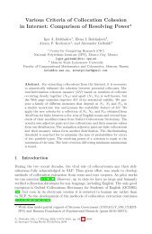
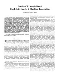
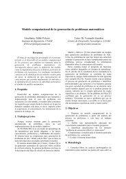
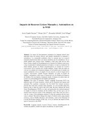
Editorial
Editorial
Editorial

Create successful ePaper yourself
Turn your PDF publications into a flip-book with our unique Google optimized e-Paper software.
<strong>Editorial</strong><br />
Natural Language Processing is a growing field in computer<br />
science and engineering, related to both theoretical and<br />
applied computational techniques relative to natural language<br />
and the use of language knowledge. This issue of the research<br />
journal “Polibits” presents four contributions concerning<br />
natural language processing. Two of them draw formal<br />
models of two categories of knowledge of language: syntax<br />
and morphology. The other two papers solve practical<br />
computational approaches of language to machine translation<br />
and information extraction.<br />
The paper “Natural Language Syntax Description using<br />
Generative Dependency Grammar” gives a practical solution,<br />
based on a Generative Dependency Grammar (GDG), to<br />
describe natural language syntax. It also presents the features<br />
and what GRAALAN, –declarative computer language in<br />
which GDG are implemented– offers.<br />
The paper “Morpheme based Language Model for Tamil<br />
Part-of-Speech Tagging” presents a POS tagging using a<br />
corpus-based approach by formulating a Language Model<br />
through morpheme components of words Tamil language. An<br />
approach to a language model is also given, in which, in order<br />
to estimate the contribution factors, the authors follow<br />
generalized iterative scaling technique.<br />
In “Modeling a Quite Different Machine Translation using<br />
Lexical Conceptual Structure”, the author outlines the<br />
readability of an Example-Based Machine Translation for any<br />
pair of languages by means of the language-independent<br />
properties of the lexical conceptual structure (LCS), which is<br />
described as a representation of traditional relationships. The<br />
author presents LCS-Based Machine Translation from the<br />
point of view of a complex adaptive system.<br />
In the paper “Named Entity Recognition in Hindi using<br />
Maximum Entropy and Transliteration”, the authors have<br />
explored different features applicable for the Hindi Named<br />
entity recognition (NER) task, as well as incorporated some<br />
gazetteer lists in the system to increase its performance. A<br />
two-phase transliteration methodology is proposed, which is<br />
not only applicable for Hindi, but also for other languages.<br />
Additionally, this issue of “Polibits” contains six regular<br />
papers addressing research of computer science applied to<br />
vision and signal processing, as well as to design of interfaces.<br />
In this way, this journal aims at the purpose of spreading the<br />
vast discipline of computer science and engineering.<br />
A definition of the simple algorithm for triangulation of the<br />
virtual object virtual, as well as an algorithm that allows<br />
visualizing of the cutting triangular net and the calculation of<br />
the dynamics of the net during the cut are presented in the<br />
paper “Visualización 3D de Deformación y Corte de Objetos<br />
Virtuales basada en Descomposición Ortogonal (3D<br />
visualization of deformation and cut of virtual objects based<br />
on orthogonal decomposition)”.<br />
In the paper “An Extended Video Database Model for<br />
Supporting Finer-Grained Multi-Policy and Multi-Level<br />
Access Controls”, the authors present a hybrid video database<br />
model. They also extend the original hierarchical indexing<br />
mechanism to add frames and salient objects at the lowest<br />
granularity level in the video tree with the aim to support<br />
multi-level access control.<br />
In “Multiplicador Electrónico para Encoder Incremental<br />
(Electronic multiplicator for incremental encoder)”, the<br />
design and experiments on simulation of the electronic<br />
multiplicator for incremental encoders are presented, which<br />
purpose is to increment the resolution of the feed back signal<br />
using the same encoder.<br />
The term “Distance Object Learning” as a way of learning<br />
over a computer network or the Internet about real world<br />
entities that are distinguishable from others is used in the<br />
paper “Distance Online Learning and Evaluation<br />
Framework”. The Distance Object Learning and Evaluation<br />
(DOLE) system concept is presented that uses standards for<br />
Learning Object Metadata (LOM), and it is based in part on an<br />
earlier version of E-learning Assessment System for Young<br />
learners (EASY).<br />
The paper “Computadoras de Bolsillo como una<br />
Alternativa para el Control de Servomotores en Robótica<br />
(PDA Computers as an Alternative for Servo Motors Control<br />
in Robotics)” proposes an implementation which is related to<br />
hardware interface, namely, to the usage of the specialized<br />
microcontroller that connects PDA with the servo motor using<br />
serial port of the PDA.<br />
In “Diseño de un Coprocesador Matemático de Precisión<br />
Simple usando el Spartan 3E (Design of Mathematical<br />
Coprocessor of Simple Precision using Spartan 3E)” the<br />
authors show how an implementation of the mathematical<br />
coprocessor using VHDL, for its further implementation in<br />
FPGA.<br />
Gerardo Sierra<br />
Head of the Group of Linguistic Engineering,<br />
Institute of Engineering,<br />
National Autonomous University of Mexico<br />
3 Polibits (38) 2008
Polibits (38) 2008<br />
4
Natural Language Syntax Description<br />
using Generative Dependency Grammar<br />
Ştefan Diaconescu<br />
Abstract— The paper presents a practical solution to describe<br />
natural language syntax. This solution is based on a Generative<br />
Dependency Grammar (GDG). A theoretical definition of these<br />
grammars and some of their proprieties is given. GDG are<br />
implemented in a declarative computer language GRAALAN<br />
(Grammar Abstract Language). The paper shortly present the<br />
features of GRAALAN and, after that, a more detailed<br />
implementation of natural language syntax description is given.<br />
GRAALAN offers for natural language syntactic description<br />
some strong features that respond to the following requests: a<br />
compact description, the possibility to express the syntax and the<br />
agreement and to specify the errors met in a text. The description<br />
has also the feature of reversibility. The paper presents some<br />
conclusions concerning the using of GRAALAN to describe the<br />
syntax (among others natural language features).<br />
T<br />
Index Terms—Dependency grammar, natural language syntax.<br />
I. INTRODUCTION<br />
HE approach of different linguistic chapters in a unified<br />
manner was realized so far in many complex systems like<br />
EUROTRA [1], EAGLES [2], ROSETTA [20]. These large<br />
projects did not produce many successful implementations,<br />
but they are very important at least from theoretical point of<br />
view. One of the major drawbacks (among others) was the<br />
lack of unity among different linguistic chapters approach.<br />
Paradoxically, this lack of unity has grown for the worse due<br />
to the (successful) standardization effort of the different<br />
linguistic chapter representation, because the extremely useful<br />
approach of each individual section was not sufficiently<br />
correlated with the approach of other linguistic sections [11].<br />
The language GRAALAN (Grammar Abstract Language) that<br />
will be very shortly presented in section II of this paper try to<br />
integrate many chapters of linguistic description and among<br />
these, the syntactic description of a natural language.<br />
A lot of language models and language grammar types were<br />
proposed trying to solve the natural language description<br />
problem. There are three of the linguistic models that seem to<br />
be more successful and used in some applications [18]: TAG –<br />
Tree Adjoining Grammar [16], HPSG – Head-Driven Phrase<br />
Structure Grammar [17] and LFG – Lexical Functional<br />
Grammar [19].<br />
During the last years another idea was more and more<br />
analyzed and studied: the dependency. Actually, it is quite an<br />
Manuscript received July 10, 2008. Manuscript accepted for publication<br />
October 20, 2008.<br />
This work was supported in part by SOFTWIN SRL, Bucharest, Romania.<br />
Stefan Diaconescu is with the SOFTWIN SRL, Bucharest, Romania (email:<br />
sdiaconescu@softwin.ro).<br />
old idea – usually [21] is used as reference but the dependency<br />
idea in the grammar is millennial – but new valences and<br />
strength became attractive. The present paper is based on<br />
some researches that try to make a connection between two<br />
directions that seemed to be almost irreconcilable till now: the<br />
generative approach and the dependency approach. We<br />
present how this connection was done and implemented in the<br />
syntactic section of a GRAALAN (section II) in order to find<br />
a more adequate language model that could be used in natural<br />
language processing and that have the potential to produce<br />
many and better applications.<br />
Some theoretical notions that are used to build<br />
GRAALAN are presented in the section III: DT - Dependency<br />
Trees, AVT - Attribute Value Trees, GDG - Generative<br />
Dependency Grammar and GDGF - Generative Dependency<br />
Grammar with Features. In section IV, it is presented how<br />
GRAALAN is used to describe the syntax under the form of<br />
rule sequence that indicates: the syntactic elements, the<br />
dependencies between these elements and the agreement<br />
between these elements. Finally (section V) some conclusions<br />
and the stage of current implementations are presented.<br />
II. GRAALAN: GRAMMAR ABSTRACT LANGUAGE<br />
GRAALAN is a language (in fact, a meta-language) that<br />
allows the description of a natural language and a<br />
correspondence between two natural languages. It contains<br />
some features that can be used to describe different natural<br />
language chapters (sections):<br />
a) Alphabet Section defines the codes of the signs used to<br />
represent and describe the natural language. In this section the<br />
following information can be put: phonetic alphabet<br />
description (using, for example IPA – International Phonetic<br />
Alphabet [13]), normal alphabet and special characters (using.<br />
for example, UNICODE [14]), groups of characters<br />
(diphthongs or triphthongs, etc.) that contain the<br />
correspondences between some sequences of normal alphabet<br />
and phonetic alphabet, alphabetic classes (vowel class,<br />
consonant class, etc.). This section can describe also some<br />
special notation systems like those used by Japanese or<br />
Chinese languages.<br />
b) Lexicon Section defines morphemes (roots, prefixes,<br />
suffixes, prefixoids, suffixoids, etc.), words (lemmas, some<br />
inflected forms of a word that accompanies the lemmas in an<br />
ordinary dictionary, for example, plural form of a noun),<br />
wordforms (some inflected form of another word that usually<br />
appears in a dictionary), multiword expression (MWE are<br />
groups of words represented as a DT - Dependency Tree),<br />
5 Polibits (38) 2008
Ştefan Diaconescu<br />
morphologic analytic structures, some typical syntactic<br />
structures (taken from the syntactic description), etc. For each<br />
lexicon entry some information belonging to the following<br />
types are present: semantic information (gloss, synonyms,<br />
antonyms, paronyms, hipernyms, hyponyms, connotations,<br />
homonyms, meronyms, etc.), etymology (original language,<br />
original form, transliteration of the original form),<br />
syllabification (euphonic, phonetic and morphologic),<br />
morphology (inflection situation, inflection rule identification,<br />
and segmentation), etc.<br />
c) Syllabification Rules Section defines the syllabification<br />
rules for: euphonic syllabification (when the word is written<br />
with the normal or special alphabet), phonetic syllabification<br />
(when the word is written with the phonetic alphabet),<br />
morphologic syllabification (that respects the morphologic<br />
structure of the word). The elements of a word “separated” by<br />
syllabification (or not) are: the normal alphabet characters,<br />
groups (diphthongs, triphthongs, etc.) described in Alphabet<br />
Section (phonetic groups), some special characters, other<br />
constitutive elements (morphemes) described in Lexicon<br />
Section (morphologic groups).<br />
d) Morphology Section defines morphologic categories and<br />
values. It is in fact an AVT - Attribute Value Tree (see section<br />
III.B), where attribute nodes are morphologic categories and<br />
value nodes are morphologic category values. Some<br />
information is attached with each type of node. For example,<br />
information attached to the attribute note is: the category<br />
name, the abbreviation of the category name, the indication if<br />
the category is inflected or not, (eventually) the name of a<br />
procedural program. Information attached to the attribute<br />
values are: the category value name, the abbreviation of the<br />
category value name, indication if it belongs to a lemma (or<br />
not), indication if it belongs to a lexicon entry (or not),<br />
(eventually) the name of a procedural program.<br />
e) Inflection Rules Section defines the rules that can be used<br />
to generate the inflected forms. Lemma (from the lexicon)<br />
indicates a Compound rule. A compound rule is a list of basic<br />
rules. A basic rule contains an AVT where each leaf has one<br />
or more associated elementary inflection rules. An elementary<br />
inflection rule contains: a condition (logical expression) that<br />
indicates when the transformation sequence must be used, a<br />
transformation sequence (insert, delete, replace words or<br />
characters) acting on normal alphabet, a transformation<br />
sequence (insert, delete, replace words or characters) acting on<br />
phonetic alphabet form, an AVT for analytic forms, relations<br />
in a DT (dependency tree, see section III.A) for analytic<br />
forms.<br />
f) Inflection Forms Section defines the inflected forms of<br />
the language. It contains an entry for an inflected form. An<br />
entry contains: the inflected form written using the normal<br />
alphabet, the inflected form written using the phonetic<br />
alphabet, the reference of the word in the lexicon whose<br />
inflected form is the current entry, the characterizing of the<br />
inflection situation (i.e., an AVT with lexical categories and<br />
lexical categories values), how the inflected form is syllabified<br />
in different situations: euphonic, phonetic, morphologic and at<br />
the end of the line (hyphenation).<br />
g) Syntax Section defines the syntax rules (this section will<br />
be detailed in the following sections of the paper).<br />
h) Bilingual Correspondences Section defines the<br />
correspondences between two languages for MWE (Multi<br />
Word Expression) correspondences [7] (it contains<br />
transformation rules based on dependency tree form of MWE,<br />
where nodes can be invariable elements, partial variable<br />
elements, total variable elements), word correspondences<br />
(particular cases of the MWE correspondences where both<br />
MWEs have only one word), syntactic structure<br />
correspondences (a particular case of MWE correspondences<br />
where the nodes can be non-terminals), morphologic analytic<br />
structure correspondences (a particular case of MWE where<br />
the correspondences is established between analytic inflection<br />
forms), morphologic sub-tree correspondences (a particular<br />
case of MWE too, that expresses the correspondences between<br />
a source morphologic sub-tree and a target morphologic subtree).<br />
III. GRAALAN THEORETICAL BACKGROUND<br />
A. Dependency Tree<br />
A generative dependency tree [3] is a 6-tuple DT = {N, T, P,<br />
A, SR, CR} where:<br />
- N - is the set of non-terminals n: n (i 1 , i 2 , …),<br />
i j ∈SR<br />
- T - is the set of the terminals t: t(i 1 , i 2 , …), i j ∈SR<br />
- P - is the set of pseudo-terminals p: p (i 1 , i 2 , …) ,<br />
i j ∈SR<br />
- A - is the set of procedural actions a: a(i 1 , i 2 , …) ,<br />
i j ∈SR<br />
- SR - is the set of subordinate relations sr: sr(i 1 ),<br />
i 1 ∈N ∪ T ∪ P ∪ A∪ CR<br />
- CR - is the set of the coordinate relations cr:<br />
cr(f 1 , f 2 ,… / s 1 , s 2 , …), f i ∈N ∪ T ∪ P ∪ A ∪ CR<br />
, s i ∈SR (f 1 , f 2 ,… are named fixed entry and s 1 ,<br />
s 2 , … are named supplementary entry).<br />
The non-terminals N are syntactic categories that can be<br />
described having a name and a structure.<br />
The terminals T are words that can be found in the lexicon<br />
or can be obtained by applying some flexional rules on words<br />
from the lexicon.<br />
The pseudo-terminals P are non-terminals that contain only<br />
terminals. When we will describe a dependency tree or a<br />
grammar we will not cover all the words from the lexicon<br />
because in this case the number of rules from the grammar can<br />
be too big. So, we can say that some non-terminals that we<br />
name pseudo-terminals (for example, some nouns or some<br />
verbs) will never be described in the grammar, but they are<br />
found in the lexicon.<br />
The procedural actions (or “actions”) A are the set of the<br />
routines that can be used to represent a certain portion of the<br />
text that we analyze. For example, a number represented like a<br />
sequence of digits or a mathematical formula or even an image<br />
Polibits (38) 2008<br />
6
Natural Language Syntax Description using Generative Dependency Grammar<br />
with a certain significance that appear in a text can be<br />
“replaced” in grammars or dependency trees by a certain<br />
procedural action.<br />
The subordinate relations SR are relations between a<br />
governor and a subordinate from the point of view of syntactic<br />
role in a phrase (for example the relation between a verb and a<br />
complement).<br />
The coordinate relation CR are relations between two or<br />
many (but usually two) syntactic parts of a phrase, for<br />
example, the relation between “read” and “write” in the<br />
phrase “I read and write.”. The coordinated elements are<br />
represented by the fixed entries. A coordinate relation can also<br />
be a governor for the elements that came eventually on its<br />
supplementary inputs (that means that the set of coordinated<br />
elements form a governor for the elements that come on the<br />
supplementary inputs).<br />
A dependency tree can be represented using the graphical<br />
symbols from Fig. 1.<br />
- NTPA has maximum one input and maximum one<br />
output;<br />
- GR has one input and one output;<br />
- CR has maximum one output, zero, one or many<br />
supplementary input and a fixed number of fixed entry (we<br />
will consider only two fixed entry).<br />
@r2@<br />
“advice”<br />
“We”<br />
@r1@<br />
“provide”<br />
@r2@<br />
“for”<br />
<br />
"......"<br />
Non-terminal<br />
Terminal<br />
%......% Pseudo-terminal<br />
#......# Action (procedure)<br />
@r2@<br />
“practical”<br />
“admin”<br />
@r2@<br />
@r5@<br />
1 2<br />
“system”<br />
@...@<br />
Governor /<br />
Subordinate relation<br />
“group”<br />
@...@<br />
Coordinate relation<br />
@r8@<br />
@r6@<br />
1 2<br />
Link<br />
Fig. 1. Graphical DT symbols.<br />
TABLE I.<br />
LINKS IN A DEPENDENCY TREE<br />
Link<br />
Link target<br />
source NTPA GR CR<br />
(supp.<br />
entry)<br />
CR<br />
(fixed<br />
entry)<br />
NTPA 1 2 7<br />
GR 3 6<br />
CR 4 5 8<br />
None 9 10<br />
None<br />
The conditions respected by the links in a dependency<br />
tree are represented in Table I (there are 10 allowed situations)<br />
where we noted:<br />
- NTPA: Non terminal (N) or Terminal (T) or Pseudo<br />
terminal (P) or Action (A).<br />
- GR: governor/subordinate relation;<br />
- CR: coordinates relation.<br />
In a graphical representation:<br />
“working”<br />
“and”<br />
Fig. 2. Example of dependency tree.<br />
We will consider also that the dependency tree is<br />
connected. As we can see, in this case, only one NTPA or one<br />
coordinate relation can have not output. This NTPA or<br />
coordinate relation will be named head.<br />
The dependency trees will be used to define generative<br />
dependency grammar (see section III.C) and generative<br />
dependency grammar with features (see section III.D).<br />
B. Attribute Value Tree<br />
An attribute value tree (AVT) [4] [9] is used to describe<br />
morphologic or syntactic structures. It is in fact a list of<br />
attributes, each attribute having one or many values and each<br />
attribute value having associated one or many attributes. It can<br />
be defined as follows, using EBNF - Extended Backus-Naur<br />
Form from [22] without capital letter / lower case letter<br />
regular expression distinction:<br />
[1] avt ::= ('{' S? label ':' S? attribute+ S? '}') | ('{' S? label S?<br />
'}' ) | ( '{' S? attribute+ '}') | (attribute+)<br />
7 Polibits (38) 2008
Ştefan Diaconescu<br />
[2] attribute ::= '[' S? S? ']'<br />
[3] ::= (label ':' S? featureContent) |<br />
featureContent | label<br />
[4] featureContent ::= attributeName S? '=' S?<br />
attributeValueList<br />
[5] attributeValueList ::= attributeValueElement ( S? ',' S?<br />
attributeValueElement)*<br />
[6] attributeValueElement ::= attributeValueName ( S? avt)*<br />
[7] attributeValueName ::= label (S label)*<br />
[8] label ::= labelChar (label)*<br />
[9] labelChar ::= '_' | '-' | '.' | 'A' | 'B' | 'C' | 'D' | 'E' | 'F' | 'G' | 'H' |<br />
'I' | 'J' | 'K' | 'L' | 'M' | 'N' | 'O' | 'P' | 'Q' | 'R' | 'S' | 'T' | 'U' | 'V'<br />
| 'W' | 'X' | 'Y' | 'Z' | 'a' | 'b' | 'c' | 'd' | 'e' | 'f' | 'g' | 'h' | 'i' | 'j' | 'k'<br />
| 'l' | 'm' | 'n' | 'o' | 'p' | 'q' | 'r' | 's' | 't' | 'u' | 'v' | 'w' | 'x' | 'y' | 'z' |<br />
'0' | '1' | '2' | '3' | '4' | '5' | '6' | '7' | '8' | '9'<br />
[10] S ::= (#x20 | #x9 | #xD | #xA)+<br />
Here S is any sequences of space, new line, carriage<br />
return or line feed characters.<br />
We can see that in the description of an AVT we can use<br />
some labels that define some sub trees: labels for attributes<br />
lists (rule [1]) and labels for attribute content (rule [3]). These<br />
labels can be used in others parts of the tree and in this<br />
manner the tree is represented more compact.<br />
A more formal definition of an AVT is given in [9]. The<br />
AVTs have different useful properties like: paths in the AVT,<br />
EC (Exclusive Combinations) in the AVT, equivalence, well<br />
formed AVT, ordering, intersection, difference, union,<br />
factoring, normalization, unifiability, unification. Among<br />
these properties, unifiability and the unification are the most<br />
important. They are used in the generation process for<br />
generative dependency grammar with features (see section<br />
III.D).<br />
C. Generative Dependency Grammar<br />
A generative dependency grammar is an 8-tuple GDG =<br />
{N, T, P, A, SR, CR, nt 0 , R} where:<br />
- N, T, P, A, SR, CR are defined like in section III.A.<br />
- nt 0 - belongs to N and is named root symbol.<br />
- R - is the set of numbered rules of the form (i) n i ::=(p i ,<br />
q i ), n i ∈ N, p i is a sequence of elements from N ∪ T ∪ P<br />
∪ A, q i is a dependency tree having nodes from p i and<br />
oriented links (relations) from SR ∪ CR.<br />
In a GDG we can make generation that will build in the<br />
same time surface texts and dependency trees.<br />
We give in the following an example of a grammar that can<br />
generate a phrase like:<br />
“We provide practical advice for system and working group<br />
administrators.”<br />
(1) ::= ( ,<br />
( r1 (())))<br />
(2) ::= ( “we”, “we”())<br />
(3) ::= ( <br />
,<br />
( r2( () ), r3( ())))<br />
(4) ::= ( ,<br />
( r4( ())))<br />
(5) ::= ( “for” , “for”(<br />
()))<br />
(6) ::= ( “and” ,<br />
r5( (), () / r6( “and”())))<br />
(7) ::= ( , ())<br />
(8) ::= ( , ( r7(<br />
())))<br />
(9) ::= ( ,( r8(<br />
())))<br />
(10) ::= ( , ())<br />
(11) ::= ( , ())<br />
(12) ::= ( “practical”, “practical”())<br />
(13) ::= ( “provide”, “provide”())<br />
(14) ::= ( “advice”, “advice”())<br />
(15) ::= ( “system”, “system”())<br />
(16) ::= ( “administrator”, “administrator”())<br />
(17) ::= ( “group”, “group” ())<br />
(18) ::= ( “working”, “working”())<br />
Using this grammar we can generate the surface text as<br />
follows:<br />
(19)(1, 2) ::= ( “we” ,<br />
“we”( r1(( ))))<br />
(20)(19,3) ::= ( “we” <br />
,<br />
“we”( r1( ( r2( ( )),<br />
r3 ( ( )))))<br />
(21)(20,13) ::= ( “we” “provide” <br />
,<br />
“we”( r1(“provide”( r2( ( )),<br />
r3( ( )))))<br />
(22)(21,4) ::= ( “we” “provide” <br />
,<br />
“we”( r1(“provide”( r2( (r4( ( )))),<br />
r3(( )))))<br />
(23)(22,5) ::= ( “we” “provide” <br />
“for” ,<br />
“we”( r1(“provide”( r2( (r4( ( )))),<br />
r3(“for”( ( ))))))<br />
(24)(23,12) ::= ( “we” “provide” “practical <br />
“for” ,<br />
“we”( r1( “provide”( r2( (r4( “practical”( )))),<br />
r3( “for”( ( ))))))<br />
(25)(24,14) ::= ( “we” “provide” “practical”<br />
“advice” “for” ,<br />
“we”( r1( “provide”( r2( “advice”(r4( “practical”( )))),<br />
r3( “for”( ( ))))))<br />
(26)(25,6) ::= ( “we” “provide” “practical” “advice”<br />
“for” “and” ,<br />
“we”( r1( “provide”( r2( “advice”(r4( “practical”( )))),<br />
r3( “for”( r5 ( ( ),<br />
( ) / r6( “and”( ))))))))<br />
(27)(26,7) ::= ( “we” “provide” “practical” “advice”<br />
“for” “and” ,<br />
“we”( r1( “provide”( r2( “advice”(r4( “practical”( )))),<br />
r3( “for”( r5 ( ( ),<br />
Polibits (38) 2008<br />
8
Natural Language Syntax Description using Generative Dependency Grammar<br />
( ) / r6( “and” ( ))))))))<br />
(28)(27,15) ::= ( “we” “provide” “practical”<br />
“advice” “for” “system” “and” ,<br />
“we”( r1( “provide”( r2( “advice”(r4( “practical”( )))),<br />
r3( “for”( r5 ( “system”( ),<br />
( ) / r6( “and”( ))))))))<br />
(29)(28,8) ::= ( “we” “provide” “practical” “advice”<br />
“for” “system” “and” ,<br />
“we”( r1( “provide”( r2( “advice”(r4( “practical”( )))),<br />
r3( “for”( r5( “system”( ),<br />
(r7( ( ))) / r6( “and”( ))))))))<br />
(30)(29,16) ::= ( “we” “provide” “practical”<br />
“advice” “for” “system” “and” <br />
“administrator”,<br />
“we”( r1( “provide”( r2( “advice”(r4( “practical”( )))),<br />
r3( “for”( r5( “system”(),<br />
“administrator”( r7( ( ))) / r6( “and”( ))))))))<br />
(31)(29,9) ::= ( “we” “provide” “practical” “advice”<br />
“for” “system” “and” “administrator”,<br />
“we”( r1( “provide”( r2( “advice”(r4( “practical”( )))),<br />
r3( “for”( r5( “system”( ),<br />
“administrator”( r7( ( r8( ( ))))) / r6(<br />
“and”( ))))))))<br />
(32)(31,17) ::= ( “we” “provide” “practical”<br />
“advice” “for” “system” “and” “group”<br />
“administrator”,<br />
“we”( r1( “provide”( r2( “advice”(r4( “practical”( )))),<br />
r3( “for”( r5( “system”( ),<br />
“administrator”( r7( “group”( r8( ( ))))) / r6(<br />
“and”( ))))))))<br />
(33)(32,11) ::= ( “we” “provide” “practical”<br />
“advice” “for” “system” “and” “group”<br />
“administrator”,<br />
“we”( r1( “provide”( r2( “advice”(r4( “practical”( )))),<br />
r3( “for”( r5( “system”( ),<br />
“administrator”( r7( “group”( r8( ( ))))) / r6(<br />
“and”( ))))))))<br />
(34)(33,18) ::= ( “we” “provide” “practical”<br />
“advice” “for” “system” “and” “working” “group”<br />
“administrator”,<br />
“we”( r1( “provide”( r2( “advice”(r4( “practical”( )))),<br />
r3( “for”( r5( “system”( ),<br />
“administrator”( r7( “group”( r8( “working”( ))))) / r6(<br />
“and”( ))))))))<br />
The final production we obtained contains in the left side of<br />
the right side the surface text and in the right side of the right<br />
side the dependency tree (represented in Fig. 2).<br />
The GDG allows obtaining a structure from an unstructured<br />
text. This structure can be used in different purposes, for<br />
example in translation process, in defining correspondences<br />
between two languages [7].<br />
D. General Dependency Grammar with Features<br />
A GDG with feature structure is a GDG where each ntpa<br />
can have associated an AVT. The AVT associated with the<br />
non-terminal from the left side of the rules have always only<br />
indexed attributes.<br />
Example<br />
Let us have the next phrase in Romanian language: “Ploile<br />
(the rains) văratice (of summer) sunt (are) călduţe<br />
(lukewarm)” that means “The summer rains are lukewarm”.<br />
We will not use all the grammatical categories involved in the<br />
analysis of this phrase but only few as an illustration.<br />
Usually, the phrase to be analyzed is first of all annotated<br />
i.e. each word will have attached his lemma and a particular<br />
AVT (that have only one value for each attribute). Each word<br />
can have many interpretations. For example “sunt” can<br />
represent the third person plural (are) or the first person<br />
singular (am). Though, for the sake of simplicity, we will<br />
consider only one interpretation for each word.<br />
The annotated phrase will be:<br />
“Ploile” ploaia [class = noun] [gender = feminine] [number<br />
= plural] “văratice” văratic [class = adjective] [gender =<br />
feminine] [number = plural] “sunt” (a) fi [class = verb]<br />
[person: III] [number = plural] [mode = indicative] [voice =<br />
active] [time = present] “călduţe” călduţ [class = adjective]<br />
[gender = feminine] [number = plural]<br />
We marked the lemmas using italics.<br />
A GDG with features that can generate this phrase can be as<br />
follows:<br />
(1) ::= ( [gender = masculine,<br />
feminine, neuter] [number = singular, plural] [person = I,<br />
II, III] [gender =<br />
masculine, feminine, neuter] [number = singular, plural]<br />
[person = I, II, III], ( @r 1 @(<br />
())))<br />
(2) [gender = masculine, feminine, neuter]<br />
[number = singular, plural] [person = I, II, III] ::=<br />
(%noun% [class = noun] [gender = masculine, feminine,<br />
neuter] [number = singular, plural] %adjective% [class =<br />
adjective] [gender = masculine, feminine, neuter]<br />
[number = singular, plural],<br />
%noun%(@r 2 @(%adjective% ())))<br />
(3) [gender = masculine,<br />
feminine, neuter] [number = singular, plural] [person = I,<br />
II, III] ::= (%verb% [class = verb] [gender = masculine,<br />
feminine, neuter] [number = singular, plural] [mode =<br />
indicative] [voice = active] [time = present, future,<br />
imperfect past] %adjective% [class = adjective] [gender =<br />
masculine, feminine, neuter] [number = singular, plural],<br />
%verb%(@r 3 @(%adjective% ())))<br />
As we can see, we used pseudo terminals for nouns, verbs,<br />
adjectives, so this grammar can generate a set of phrases.<br />
IV. NATURAL LANGUAGE SYNTAX DESCRIPTION IN GRAALAN<br />
A. General Structure<br />
The description of the syntax in GRAALAN [8] [10] will<br />
use GDG and AVT presented in section III. The language<br />
where we are describing the syntax must respect the following<br />
conditions:<br />
a) Syntax: The description language will allow the<br />
description in a detailed and compact form of the manner to<br />
9 Polibits (38) 2008
Ştefan Diaconescu<br />
combine words in phrases respecting the rules of a natural<br />
language grammar.<br />
b) Dependencies: We accept here that the dependency<br />
aspects are reduced to the mode different parts of a phrase are<br />
in relation one another (coordinate and governor/subordinate<br />
relations).<br />
c) Agreement: By agreement [5] we will understand the<br />
mode different part of speech “match” one another when they<br />
are in certain dependency relations from the point of view of<br />
the values of different morphologic or syntactic categories.<br />
d) Errors: The natural language syntax description must<br />
allow indicating the errors (at least the most frequent ones)<br />
that can be found in phrases. The bad built phrases must be<br />
recognized (in a certain measure) and marked as being<br />
incorrect.<br />
e) Reversibility: By reversibility we will understand the<br />
property of the description language to be used to convert a<br />
source (surface) text in a deep structure (the dependency tree,<br />
in our case) and to convert the deep structure into the surface<br />
text.<br />
We will give here an informal definition of natural<br />
language syntax description in GRAALAN. A more detailed<br />
definition of natural language syntax description in<br />
GRAALAN is given in the next sections.<br />
A GRAALAN syntax description is a sequence of labeled<br />
rules. A rule has two parts: the left part and the right part. The<br />
left part of a rule contains a non terminal and an AVT. The<br />
AVT contains syntactic / morphologic categories with their<br />
values. The right part of a rule contains one or many<br />
Alternants. An alternant is formed by a set of subsections: the<br />
syntactic subsection, the dependency subsection and the<br />
agreement subsection.<br />
a) The syntactic subsection is a sequence of (eventually<br />
labeled) one or many NTPAs. Each NTPA can have<br />
associated information about how this NTPA is linked with<br />
others NTPA by certain relations from the dependency<br />
subsection (these relations are indicated by their labels in the<br />
dependency subsection). There are three lists concerning the<br />
relations: coordinated list (CL), subordinated list (SL) and<br />
government list (GL).<br />
Each NTPA can have associated an AVT describing<br />
syntactic / morphologic categories with their values.<br />
b) The dependency subsection contains the description of<br />
the relations between the NTPA from the syntactic subsection<br />
(referred by their labels). There are two types of relations:<br />
The subordinate relation SR is a relation between two N, T,<br />
P, A, or a coordinate relation CR. One of the two elements is<br />
considered to be the governor (that governs by SR) and the<br />
other the subordinate (that is governed by SR).<br />
The coordinate relation CR is a relation between (usually)<br />
two N, T, P, A (that are said to be coordinated by CR), and<br />
eventually one or many SR (by which the CR is considered to<br />
be a governor for others N, T, P, A, or CR).<br />
c) The agreement subsection contains a list of agreement<br />
rules. An agreement rule is a conditional expression expressed<br />
between the categories values of the NTPAs from the<br />
syntactic subsection. It can indicate some actions like error<br />
messages or how the analyze will be continued after an<br />
agreement error is found.<br />
Left part<br />
<br />
[AVT]<br />
Alternant<br />
sequence<br />
=><br />
Alt. 1<br />
Alt. 2 ....<br />
Alt. 3 ....<br />
Grammar Rule<br />
Synt.<br />
subsection<br />
Dep.<br />
subsection<br />
Agr.<br />
subsection<br />
Fig. 3. Syntax rule elements<br />
B. Graalan Syntactic Section Header<br />
The syntactic section of a GRAALAN description is a<br />
sequence of rules preceded by a header. The description of the<br />
header in EBNF is the following:<br />
[1] syntaxSection ::= 'Section' S 'syntax' S sectionHeader<br />
syntax S 'end' S 'of' S 'section'<br />
[2] sectionHeader ::= (sourceLanguage,<br />
exploitationLanguage, sourceDirection,<br />
exploitationDirection)<br />
A header is formed by elements that refer the source<br />
language and exploitation language.<br />
[3] S ::= (#x20 | #x9 | #xD | #xA)+<br />
Right part<br />
CL/SL/GL<br />
[AVT]<br />
“T” CL/SL/GL<br />
[AVT]<br />
%P% CL/SL/GL<br />
[AVT]<br />
#A# CL/SL/GL<br />
[AVT]<br />
@CR @<br />
CL/SL/GL<br />
@GR@ SL/GL<br />
- agreement<br />
rules with<br />
condition<br />
expressions and<br />
actions<br />
Here S is any sequences of spaces, new line, carriage<br />
return or line feed characters.<br />
[4] sourceLanguage ::= 'Source' S 'language' S language S<br />
[5] exploitationLanguage ::= 'Exploitation' S 'language' S<br />
language S<br />
[6] sourceDirection ::= 'Source' S 'direction' S ('left' | 'right')<br />
Polibits (38) 2008<br />
10
Natural Language Syntax Description using Generative Dependency Grammar<br />
[7] exploitationDirection ::= 'Exploitation' S 'direction' S ('left'<br />
|'right')<br />
[8] language ::= ('RUM' | 'FRA' | 'FRA' | 'SPA' | 'RUS, ...')<br />
We understand by direction the mode to scan the source<br />
text: right - the scan is done from left to right; left - the scan is<br />
done from right to left. The language is indicated according to<br />
[15].<br />
[9] syntax ::= (rule S)+<br />
[10] rule ::= 'Rule' S label ':' S '' S? attribute*<br />
S? '::=' S? (('Alternant' S label ':' S? alternantContent)+ |<br />
('Alternant' S alternantContent))<br />
The alternant labels must be unique in the rule.<br />
[11] name ::= label (S label)*<br />
[12] label ::= labelChar (label)*<br />
[13] labelChar ::= '_' | '-' | '.' | 'A' | 'B' | 'C' | 'D' | 'E' | 'F' | 'G' | 'H'<br />
| 'I' | 'J' | 'K' | 'L' | 'M' | 'N' | 'O' | 'P' | 'Q' | 'R' | 'S' | 'T' | 'U' |<br />
'V' | 'W' | 'X' | 'Y' | 'Z' | 'a' | 'b' | 'c' | 'd' | 'e' | 'f' | 'g' | 'h' | 'i' | 'j'<br />
| 'k' | 'l' | 'm' | 'n' | 'o' | 'p' | 'q' | 'r' | 's' | 't' | 'u' | 'v' | 'w' | 'x' | 'y' |<br />
'z' | '0' | '1' | '2' | '3' | '4' | '5' | '6' | '7' | '8' | '9'<br />
[14] alternantContent ::= (syntacticSubsection<br />
((dependencySubsection agreementSubsection?) |<br />
agreementSubsection)?)<br />
An alternant can contain the three types of subsection<br />
(syntactic, dependency and agreement) in different<br />
combinations.<br />
C. Syntactic Subsection<br />
The syntactic subsection of a GRAALAN syntax rule<br />
contains information about a set of NTPAs that must be found<br />
in the analyzed / generated source text, in the corresponding<br />
sequence. The description of the syntactic subsection in EBNF<br />
is the following:<br />
[15] syntacticSubsection ::= 'Syntax' S (( notRelationedNTPA<br />
S tpaRelationalList*)+) | (( notRelationedNTPA S<br />
nRelationalList*)+)<br />
[16] notRelationedNTPA ::= ( label ':' S? )? ( ( '' ) | ( '"' terminal '"' ) | ( '%' S? name S? '%' ) | ( '#' S?<br />
label S? '#' ) ) S attribute* (S ntpaBehaviour)*<br />
[17] terminal ::= char (terminal)*<br />
[18] char ::= &label; | &code;|...<br />
Here char can be &label; or &code; or any character<br />
defined in GRAALAN Alphabet section (not described in this<br />
paper).<br />
[19] code ::= '#x' hexaString<br />
[20] hexaString ::= hexaChar (hexaString)*<br />
[21] hexaChar ::= '0' | '1' | '2' | '3' | '4' | '5' | '6' | '7' | '8' | '9' | 'a' |<br />
'b' | 'c' | 'd' | 'e' | 'f' | 'A' | 'B' | 'C' | 'D' | 'E' | 'F'<br />
[22] ntpaBehaviour ::= ntpaBehaviourElement (S<br />
ntpaBehaviourElement)*<br />
[23] ntpaBehaviourElement ::= '!' | ( ( 'OK' | 'KO' ) S? '=' S? (<br />
'OK' | 'KO' ) ) | ( 'Message' S? = S? label ) | ('Context' S?<br />
= S? '(' S? label (S label)* S? ')' ) )<br />
Each element from ntpaBehaviourElement that<br />
characterises the NTPA behavior can appear only once in an<br />
ntpaBehaviour.<br />
An NTPA that is head can have associated a feature named<br />
“cut” and indicated by “!”. This means that the head loses the<br />
characteristic of head. The corresponding NTPA will not have<br />
relations with other NTPAs. The grammar must be written in<br />
order to obtain a connected dependency tree. One alternant<br />
will have only one head. When we use another rule to<br />
substitute a non terminal in the current alternant, the different<br />
links of the substituted non-terminal will be applied to the<br />
head of the used rule.<br />
The others elements that appear in ntpaBehaviourElement<br />
form the error sequence. In such a sequence the Message is<br />
mandatory. The error message itself is indicated by a label<br />
that defines the error text in another GRAALAN section (the<br />
GRAALAN Message Section that is not presented in this<br />
paper).<br />
The condition ('OK' | 'KO') S? '=' S? ('OK' | 'KO') indicates<br />
the error triggering. The left of “=” indicates how NTPA<br />
treatment is terminated and the right side of “=” indicates the<br />
error condition, see Table II.<br />
TABLE II<br />
ERROR TRIGGERING FOR A NTPA<br />
How NTPA treatment<br />
is terminated<br />
Error<br />
condition<br />
OK OK Yes (i)<br />
OK KO No<br />
KO KO Yes(ii)<br />
KO OK No<br />
Continue as it<br />
was not an error<br />
The two cases when the treatment is continued as it were<br />
not an error has the following significance:<br />
i) We found an error but this error is described as it was<br />
correct.<br />
Example<br />
(A simplified description.)<br />
::=<br />
"," <br />
"!"|<br />
"!"<br />
The first alternant corresponds to a phrase of the form (in<br />
Romanian):<br />
"Domnilor, vorbiţi mai încet !" (Gentlemen, shut up!)<br />
(with a comma after the vocative).<br />
The second alternant corresponds to a phrase of the form<br />
(in Romanian):<br />
"Domnilor vorbiţi mai încet!" (Gentlemen shut up!)<br />
(without a comma after the vocative, therefore incorrect).<br />
Though we have an error, the sense remains clear.<br />
11 Polibits (38) 2008
Ştefan Diaconescu<br />
During the analysis of this incorrect phrase, the second<br />
alternant will return an OK value after the terminal "!". If we<br />
attach in the second alternant an error condition we will can<br />
indicated the error apparition:<br />
Rule R1: ::=<br />
Alternant A1:<br />
Syntax<br />
Label1:<br />
Coordinate Label5(1)<br />
Label2: ","!<br />
Label3: <br />
Coordinate Label5(2)<br />
Label4: “!”!<br />
Dependencies<br />
Label5: @vocative relation@(2)<br />
Alternant A2:<br />
Syntax<br />
Label1: <br />
Coordinate Label4(1)<br />
Label2: <br />
OK = OK Message =<br />
ErrorMessage<br />
Coordinate Label4(2)<br />
Label3: "!"!<br />
Dependencies<br />
Label4: @vocative relation@(2)<br />
ii) There are situations when an NTPA must return OK but,<br />
if it returns KO, we have an error that must be identified as it<br />
is. Let us suppose a grammar fragment that must recognize<br />
phrases formed by a verbal group or by two verbal groups<br />
linked by “and”.<br />
(A simplified description.)<br />
::= "."|<br />
"and""."<br />
In such a grammar, after an “and” was detected, a must be found. We can attach to the non terminal<br />
that is written after “and” an error sequence<br />
that must be triggered to KO return by this non terminal<br />
(giving an error message). A phrase like “He came and.” must<br />
produce this error message<br />
The (simplified) description could be, for example:<br />
Rule R1: ::=<br />
Alternant A1: "."<br />
Alternant A2: "and"<br />
KO = OK Message =<br />
Error101<br />
"."<br />
A more detailed description:<br />
Rule R1 ::=<br />
Alternant A1:<br />
Syntax<br />
Label1: Governor Label4<br />
Label2: Subordinate Label4<br />
Label3: "."!<br />
Dependencies<br />
Label4: @nominal / verbal relation@<br />
Alternant A2:<br />
Syntax<br />
Label1: Governor Label7<br />
Label2: Coordinate<br />
Label6(1)<br />
Label3: "and"!<br />
Label4: <br />
KO = OK Message = Error101<br />
Coordinate Label6(2)<br />
Label5 "."!<br />
Dependencies<br />
Label6: @”and” coordination@(2)<br />
Subordinate Label7<br />
Label7: @nominal / verbal relation@<br />
[24] tpaRelationalList ::= ( 'Governor' S labelList ) | (<br />
'Subordinate' S labelList ) | ( 'Coordinate' label S? '(' S? (<br />
'1’ | '2' S? ) ')' )<br />
[25] nRelationalList ::= ( 'Governor' S labelList ) | (<br />
'Subordinate' S labelList ) | ( 'Coordinate' label S? '(' S? (<br />
'1’ | '2' S? ) ')' ) | ( 'External' labelList)<br />
[26] labelList ::= label (S label)*<br />
A NTPA with relations is an NTPA that is linked with other<br />
NTPAs by relations (governor, subordinate, coordinate).<br />
The Subordinate list of an NTPA can contain only the label<br />
of a Subordinate relation from the Dependency subsection.<br />
The Coordinate list of an NTPA can contain only one label<br />
of a coordinate relation (that will be referred on a fixed entry)<br />
from Dependency subsection.<br />
The Governor list of an NTPA can contain one or many<br />
labels of subordinate relations from the Dependency<br />
subsection.<br />
For the same NTPA: the Subordinate list and Governor list<br />
can coexist, the Governor list and the Coordinate list can<br />
coexist, and the Subordinate list and the Coordinate list are<br />
exclusive.<br />
The External list of can appear only for a nonterminal. It<br />
refers relations from Dependency subsection that appear wit<br />
the attribute Definition or Reference [6]. We must respect the<br />
discipline that, in the process of applying the rules (the<br />
generation of a new rule from two rules) always the external<br />
“definition” must appear before the corresponding external<br />
“reference”. An external definition can appear only in a<br />
relational list of a non terminal, because only a non terminal<br />
can carry them further to someone that needs it.<br />
D. Dependency Subsection<br />
The dependency subsection of an alternant contains<br />
information about the relations that are defined between the<br />
NTPAs from the syntactic subsection of the alternant. The<br />
description of the dependency subsection in EBNF is the<br />
following:<br />
Polibits (38) 2008<br />
12
Natural Language Syntax Description using Generative Dependency Grammar<br />
[27] dependencySubsection ::= 'Dependencies' S<br />
(coordinateRelation | subordinateRelation)+<br />
[28] coordinateRelation ::= label ':' S? ( ( ( 'Reference' S ) | (<br />
'Definition' ' S ')) ? '@' S? name S? '@' S? '(' S? '2' S? ')'<br />
(S? '!')? ( ( 'Subordinate' S label )? | ( 'Coordinate' S label<br />
S? '(' S? ( '1' | '2' ) S? ')' )?) ( 'Governor' ( S label ) | (S<br />
label S? '(' S? ( '1' | '2' ) S? ')' )+ )?<br />
A coordinate relation label must be unique among the<br />
alternant labels.<br />
The 'Reference' key word indicates (if present) that the<br />
current coordinate relation is not defined in the current rule<br />
but it is referred from another rule.<br />
The 'Definition' key word indicates (if present) that the<br />
current coordinate relation is defined in the current rule and it<br />
will be referred from other rules.<br />
A coordinate relation can be followed by cut (“!”) because<br />
a coordinate relation can be head and using cut this feature<br />
will be discarded.<br />
The Subordinate list of a coordinate relation can contain<br />
only one label of a subordinate relation from Dependency<br />
subsection.<br />
The Coordinate list of a coordinate relation can contain<br />
only one label of a coordinate relation from Dependency<br />
subsection (referred on a fixed entry).<br />
The Governor list of a coordinate relation can contain one<br />
or more labels of governor / subordinate relation from<br />
Dependency subsection. The current coordinate relation can<br />
be:<br />
- governor for other NTPAs or coordinate relations (using a<br />
governor / subordinate relation indicated by a label not<br />
followed by a number in parenthesis); this means that the links<br />
from these governor / subordinate relations will come on the<br />
current coordinate relation on supplementary inputs);<br />
- “governor” for other NTPAs or coordinate relations (using<br />
a label followed by a number of a fixed entry); this means that<br />
the links from these NTPAs or coordinate relations will<br />
appear on the corresponding fixed entry of the current<br />
coordinate relation.<br />
For the same coordinate relation: the Subordinate list and<br />
the Coordinate list are exclusive and each of them can coexist<br />
with Governor list.<br />
[29] subordinateRelation ::= label ':' S? ( ( ( 'Reference' S ) | (<br />
'Definition' ' S ')) ? '@' S? name S? '@' ( ( 'Subordinate' S<br />
label )? , ('Governor' S label )? )<br />
A subordinate relation label must be unique among the<br />
alternant labels.<br />
A subordinate relation has always one entry; so, we do not<br />
need to specify the number of entries. In fact, the presence of<br />
the entry number in coordinate relation indicates the fact that<br />
it is a coordinate relation.<br />
The 'Reference' and 'Definition' key words have the same<br />
significance as for coordinateRelation.<br />
The Subordinate list of a subordinate relation can contain<br />
only one label of a coordinate relation from the Dependency<br />
subsection (where it will go on a supplementary input) or of<br />
an NTPA from the Syntax subsection.<br />
The Governor list of a subordinate relation contains only<br />
one label of an NTPA from the Syntax subsection or of a<br />
coordinate relation from the Dependency subsection.<br />
Observation 1: Because a link has two extremities, it can<br />
be indicated by the any of its ends or by both. There are many<br />
ways to indicate a link according to its type. It is advisable to<br />
make the grammar description in such a way that a link appear<br />
only once (to the element from where the link leaves or to the<br />
element where the link arrives). See TABLE III where we use<br />
the notations:<br />
GR = Governor/Subordinate Relation<br />
CR = Coordinate relation<br />
SL = Subordinate List<br />
GL = Governor List<br />
CL = Coordinate List<br />
TABLE III<br />
INDICATION OF LINKS<br />
Link<br />
type<br />
Link<br />
source<br />
(label<br />
A)<br />
Link<br />
target<br />
(label<br />
B)<br />
How the link is indicated<br />
1 2<br />
1 NTPA GR B in SL of A A in GL of<br />
B.<br />
2 NTPA CR (on<br />
fixed<br />
entry)<br />
B in CL of A<br />
(with fixed<br />
entry number<br />
A in GL of<br />
B (with<br />
fixed entry<br />
of B)<br />
of B)<br />
3 GR NTPA B in SL of A A in GL of<br />
B<br />
B in SL of A<br />
4 GR CR (on<br />
supp.<br />
entry)<br />
A in GL of<br />
B<br />
5 CR GR B in SL of A A in GL of<br />
B<br />
6 CR CR (on<br />
fixed<br />
entry<br />
B in CL of A<br />
(with fixed<br />
entry number<br />
of B)<br />
A in GL of<br />
B (with<br />
fixed entry<br />
number of<br />
B)<br />
Observation 2: In the Table IV it is indicated that we can<br />
put in different relational lists function of the element that the<br />
list belongs to.<br />
Example<br />
… ::= …<br />
{Sequence:<br />
(gender = masculine, feminine, neutral)<br />
(number = singular, plural)}<br />
{Sequence}<br />
{Sequence}<br />
TABLE IV<br />
THE RELATIONAL LIST CONTENT<br />
13 Polibits (38) 2008
Ştefan Diaconescu<br />
List<br />
type<br />
GL<br />
SL<br />
CL<br />
List<br />
List content<br />
owner<br />
NTPA The labels of one or many governor /<br />
subordinate relations that have outputs<br />
going to the current NTPA.<br />
GR The label of a coordinate relation or of an<br />
NTPA that have outputs going on the<br />
input of the current governor /<br />
subordinate relation.<br />
CR The labels of one or many governor /<br />
subordinate relation (that have outputs<br />
going to the supplementary input of the<br />
current coordinate relation) and / or<br />
labels of some NTPAs or other<br />
coordinate relation that have outputs<br />
going on fixed entries of the current<br />
coordinate relation. In this case, the<br />
corresponding number of fixed entry is<br />
indicated too.<br />
NTPA The label of only one governor /<br />
subordinate relation that have an input<br />
where the output of the current NTPA<br />
goes.<br />
GR The label of a coordinate relation (where<br />
the output of the current governor /<br />
subordinate relation will go on a<br />
supplementary input) or of an NTPA<br />
(that have an entry where the output of<br />
the current governor / subordinate<br />
relation will go).<br />
CR The label of a governor / subordinate<br />
relation that has an input where the<br />
output of the current coordinate relation<br />
will go.<br />
NTPA The label of only one coordinating<br />
relation (where the output of the current<br />
NTPA will go on a fixed entry). In this<br />
case the number of the fixed entry is also<br />
indicated.<br />
CR The label of only one coordinating<br />
relation (where the output of the current<br />
coordinate relation will go on a fixed<br />
entry). In this case the number of the<br />
fixed entry is also indicated.<br />
1<br />
1<br />
GR<br />
SL (1 elem.)<br />
CR<br />
CR<br />
GR<br />
2<br />
or<br />
NTPA<br />
GR<br />
SL (1 elem.)<br />
GR<br />
2<br />
SL (1 elem.)<br />
1<br />
or<br />
or<br />
or<br />
CR<br />
GR<br />
CL (1 elem.)<br />
RL (n elem.)<br />
CR<br />
Obs.: SL and CL<br />
are exclusive.<br />
NTPA<br />
Obs.: GR has<br />
not CL<br />
Fig. 4. The content of Governor, Subordinate and Coordinate lists<br />
(GL, SL, CL)<br />
[30] attribute ::= notIndexedAttribute | indexedAttribute | '{'<br />
S? label ':' S? attribute+ S? '}' | '{' S? attribute+ S? '}' | '{'<br />
S? label S? '}'<br />
In this representation, the label of an attribute sequence<br />
allows to compact the rule. If the same attribute sequence<br />
appears many times in a rule (in the left side or in the<br />
alternants from the right side), then the first apparition of the<br />
sequence can be labeled and the following apparitions can be<br />
indicated only by using this label. A label of an attribute<br />
sequence must be unique in the current rule.<br />
[31] notIndexedAttribute ::= '(' ( ( ( S? label ':' S? )?<br />
attributeContent ) | label ) ')'<br />
[32] indexedAttribute ::= '[' ( ( ( S? label ':' S?)?<br />
attributeContent) | label ) ']'<br />
[33] attributeContent ::= category S? '=' S? categoryValue ( S?<br />
',' S? categoryValue )*<br />
In this representation, the label of an attributeContent<br />
allows to compact the rule. If the same attribute appears many<br />
times in a rule (in the left side or in the alternants from the<br />
2<br />
1<br />
GL (1 elem.)<br />
1<br />
NTPA<br />
CR<br />
2<br />
CL (1 elem.)<br />
GL (n elem.)<br />
Obs.: SL and CL<br />
are exclusive.<br />
2<br />
Polibits (38) 2008<br />
14
Natural Language Syntax Description using Generative Dependency Grammar<br />
right side), then its first apparition can be labeled and the<br />
following apparitions can be indicated only by using this<br />
label. A label of an attribute must be unique in the current<br />
rule.<br />
Example<br />
… ::= …<br />
(Gender1: gender = masculine, feminine,<br />
neutral)<br />
(Number1: number = singular, plural)<br />
<br />
(Gender2: gender = masculine, feminine)<br />
(Number2: number = singular)<br />
<br />
(Gender1) (Number1)<br />
<br />
(Gender2) (Number2)<br />
If an indexedAttribute contains a label then this label will<br />
play the role of an index. If the indexedAttribute do not have a<br />
label, then the category from attributeContent will play the<br />
index role. In any cases, categoryValue from attributeContent<br />
represent all the values that the index can take.<br />
Example<br />
Let us have a set of rules of the form:<br />
<br />
[person = I, II, III]<br />
[number = sg, pl]<br />
[gender = m, f, n]<br />
::=<br />
Alternant A1:<br />
<br />
[person = I, II, III]<br />
[number = sg, pl]<br />
[gender = m, f, n]<br />
Alternant A2:<br />
<br />
[person = I, II, III]<br />
[number = sg, pl]<br />
[gender = m, f, n]<br />
Alternant A3:<br />
<br />
[person = I, II, III]<br />
[number = sg, pl]<br />
[gender = m, f, n]<br />
Alternant A4:<br />
<br />
[person = I, II, III]<br />
[number = sg, pl]<br />
[gender = m, f, n<br />
Considering the combinations for person, number and<br />
gender, this rule represents in fact 18 rules.<br />
Example<br />
The same thing can be written more compact as follows:<br />
<br />
[e1: persoana = I, II, III]<br />
[e2: number = sg, pl]<br />
[e3: gen = m, f, n]<br />
::=<br />
Alternant A1:<br />
[e1][e2][e3]<br />
Alternant A2:<br />
[e1][e2][e3]<br />
Alternant A3:<br />
[e1][e2][e3]<br />
Alternant A4:<br />
[e1][e2][e3]<br />
Example<br />
A more important using of the indexing is when the<br />
same category must serve as index in many ways in the same<br />
alternant.<br />
<br />
[e1: attribute1 = value11, value12, value13]<br />
[e2: attribute2 = value21, value22]<br />
[e3: attribute3 = value31, value32, value33]<br />
::=<br />
Alternant A1:<br />
[e1][e2][e3]<br />
<br />
[e4: attribute1 = value11, value12, value13]<br />
[e5: attribute2 = value21, value22, value23]<br />
[e6: attribute3 = value31, value32, value33]<br />
[e4][e5][e6]<br />
In this example, the attributes e1: attribute1, e2: attribute2,<br />
e3: attribute3 are considered as indexes different from e4:<br />
attribute1, e5: attribute2, e6: attribute3 (i.e., for example,<br />
and must have the same<br />
value for attribute1, and <br />
must have the same value for attribute1 but the values for<br />
attribute1 can be different in and in , etc.)<br />
[34] categoryValue ::= name S attribute*<br />
We can see that a categoryValue can be followed by an<br />
attribute sequence. In this way, a branching in an attribute<br />
value tree is represented. A sequence of “category = value”<br />
that pass by such branching points represents a path in the<br />
AVT. The syntax must be written in such a way that a path do<br />
not have many apparition of the same category.<br />
E. Agreement Subsection<br />
The agreement subsection of an alternant describes the<br />
conditions that must be respected by the morphologic /<br />
syntactic categories of the NTPA from the syntactic<br />
subsection. The description of the agreement subsection in<br />
EBNF is the following:<br />
[35] agreementSubsection ::= 'Agreement' agreementRule+<br />
[36] agreementRule ::= 'if' S? '(' S? conditionExpression S? ')'<br />
S? alternatives+ (( S? 'else' S? '(' S? agreementRule S? ')'<br />
15 Polibits (38) 2008
Ştefan Diaconescu<br />
S? ) | ( S? 'else' S? agreementRule S? ) | ( S? 'else' S? '('<br />
S? actionList S? ')' ) )?<br />
[37] alternatives ::= ('true' S? '(' S? expression S? ')' ) | ('false'<br />
S? '(' S? expression S? ')' ) | ( 'not' S? 'applicable' S? '(' S?<br />
expression S? ')' ) | ( 'not' S? 'determinated' 'S? (' S?<br />
expression ')' )<br />
[38] expression ::= actionList | agreementRule<br />
A conditionExpression can have one of the four truth<br />
values. We will use a tetravalent logic that has the following<br />
truth values: TRUE, FALSE, NOT APPLICABLE, NOT<br />
DETERMINATE. Therefore, after 'if' S? '(' S?<br />
conditionExpression S? ')' S? we must have a list of maximum<br />
four alternatives and these alternatives must be different. If<br />
some alternatives are missing, they can globally be treated<br />
using else.<br />
Example<br />
Let us have the following sequence:<br />
if (conditionExpression)<br />
true(expression 1)<br />
not applicable(expression 2)<br />
else(expression 3)<br />
Such an expression is read: "if conditionExpression is true<br />
then execute expression1 and if conditionExpression is not<br />
applicable then execute expression2 otherwise (i.e.<br />
conditionExpression is false or not determinated) then execute<br />
expression3”.<br />
[39] conditionExpression ::= ( '(' S? conditionExpression S? ')'<br />
S? logicalOperator S? conditionExpression ) | ( S? '~' S?<br />
'(' S? conditionExpression S? ')' S? logicalOperator S?<br />
conditionExpression ) | ( '(' S? conditionExpression S? ')' )<br />
| ('~' S? '(' S? conditionExpression S? ')' ) |<br />
(simpleExpression S? logicalOperator S?<br />
simpleExpression ) | simpleExpression<br />
In order to formulate the logical value of the<br />
conditionExpression we can use logicalOperators (including<br />
the negation “~”), parenthesis and operands that are<br />
simpleExpression.<br />
[40] logicalOperator ::= 'and' | 'or'<br />
[41] simpleExpression ::= ({operand} S? '+ S? {operand} S?<br />
'' S? {operand})<br />
[42] operand ::= label attribute+<br />
An operand indicates an NTPA that is involved in the<br />
agreement. The agreement is usually expressed between a<br />
governor and a subordinate. Let us have the example: “Not<br />
only the rain but also the wind corrode the cliffs.” Between<br />
“Not only the rains but also the winds” as multiple subject<br />
and “corrode” must be described an agreement. (We can also<br />
describe a sort of agreement also between “not only” and “but<br />
also” as two parts of a correlation.)<br />
If we have a governor / subordinate relation, then the<br />
operator representing the governor will be at left of “” (the arrow looks at the governor).<br />
An expression of the form operand 1 + operand 2 operand 1 + operand 2 is read: “if<br />
operand 1 has some features a 1 (attributes and values: a certain<br />
gender, a certain number, etc.) and operand 2 has certain<br />
features a 2 then the operand 3 must have certain features a 3 .<br />
An expression operand 1 <br />
operand 1 is read: “if operand 1 has certain features a 1 then<br />
operand 2 must have certain features a 2 ”.<br />
The operand contains a label of an NTPA (from the<br />
syntactic subsection of the current alternant) involved in the<br />
agreement and an attribute under the form of an AVT.<br />
An AVT (indicated by attribute) of an operand must be<br />
unifiable with the AVT associated to the corresponding NTPA<br />
(indicated by label).<br />
A simpleExpression is TRUE when all its operands have<br />
AVTs unifiable with the corresponding AVT from the<br />
syntactic subsection.<br />
A simpleExpression is FALSE when the AVT<br />
corresponding to the operands represented the governor is<br />
unifiable with the corresponding AVT of NTPA from<br />
syntactic subsection and those representing the subordinate<br />
are not.<br />
A simpleExpression is NOT APPLICABLE if at least one<br />
of the operands representing the governor has a not unifiable<br />
AVT.<br />
(A value of NOT DETERMINED can appear only by the<br />
evaluation of the conditionExpression containing simple<br />
expressions.)<br />
Example<br />
Let us have two non terminals that appear in syntactic<br />
subsection of an alternant:<br />
Label1: <br />
Label2: <br />
(a = av1, av2)<br />
(b = bv1, bv2, bv3)<br />
(c = cv1, cv2, cv3)<br />
(d = dv1, dv2)<br />
(e = ev1, ev2, ev3)<br />
(f = vf1, vf2, vf3)<br />
Let us have the simple expression of the form:<br />
Label1(a = av1, av2)(b = bv2, bv3) -> Label2(e =ev1, ev2)(f =<br />
vf2)<br />
During the syntactic analysis, after the current alternant was<br />
analyzed and recognized in source text, and<br />
will have only some of the above<br />
attributes/values.<br />
The operand Label1(a = av1, av2)(b = bv2, bv3) will be<br />
unifiable with when this one will have after<br />
the syntactic analysis:<br />
Polibits (38) 2008<br />
16
Natural Language Syntax Description using Generative Dependency Grammar<br />
- the category a with the values av1 or av2;<br />
- the category b with the values bv1 or bv3.<br />
The operand Label2(e =ev1, ev2)(f = vf2) will be unifiable<br />
with the when this one will have after the<br />
syntactic analysis:<br />
- the category e with the values ev1 or ev2;<br />
- the category f with the value vf2.<br />
Example<br />
Let us have two non terminals that appear in syntactic<br />
subsection of an alternant:<br />
Label1: <br />
(negation = affirmative, negative)<br />
(person = I, II)<br />
(number = singular)<br />
(gender = masculine, feminine)<br />
Label2: <br />
(negation = affirmative, negative)<br />
(person = I, II)<br />
(number = singular)<br />
(gender = masculine, feminine)<br />
Let us have the expression of the form:<br />
Label1(person = I)
Ştefan Diaconescu<br />
Formalism and Virtual Machine Study. Final Report. Commission of the<br />
European Communities, 1991.<br />
[2] R. Backofen et al. EAGLES Formalism Working Group Final Report.<br />
Expert Advisory Group on Language Engineering Standards, 1996.<br />
[3] S. Diaconescu. Natural Language Understanding Using Generative<br />
Dependency Grammar. In: M. Bramer, A. Preece and F. Coenen (Eds),<br />
Twenty second SGAI International Conference on Knowledge Based<br />
Systems and Applied Artificial Intelligence, pp.439-452, Cambridge UK,<br />
Springer, 2002.<br />
[4] S. Diaconescu. Morphological Categorization Attribute Value Trees and<br />
XML. In: M. A. Klopotek, S. T. Wierzchon, K. Trojanowski (Eds),<br />
Intelligent Information Processing and Web Mining, Proceedings of the<br />
International IIS: IIPWM’03 Conference, pp. 131-138, Zakopane,<br />
Poland, Springer, 2003.<br />
[5] S. Diaconescu. Natural Language Agreement Description for Reversible<br />
Grammars. In: T. D. Gedeon, L. C. C. Fung (Eds.), Advances in<br />
Artificial Intelligence, 16 th Australian Conference on AI, pp. 161-172,<br />
Perth, Australia, Springer, 2003.<br />
[6] S. Diaconescu. Natural Language Processing Using Generative Indirect<br />
Dependency Grammar. In: M. A. Klopotek, S. T. Wierzchon, K.<br />
Trojanowski (Eds), Intelligent Information Processing and Web Mining,<br />
Proceedings of the International IIS, IIPWM’04 Conference, pp. 414-<br />
418, Zakopane, Poland, Springer, 2004.<br />
[7] S. Diaconescu. Multiword Expression Translation Using Generative<br />
Dependency Grammar. In: J. L. Vicedo, P. Martinez-Barco, R. Muñoz,<br />
M. S. Noeda (Eds.), Advances in Natural Language Processing,<br />
Proceedings of 4th International Conference, ESTAL 2004, pp. 243-254,<br />
Alicante, Spain, Springer, 2004.<br />
[8] S. Diaconescu. GRAALAN – Grammar Abstract Language Basics. In: J.<br />
M. Jun, B. M. Bae, K. Y. Lee (Eds) GESTS International Transaction on<br />
Computer Science and Engineering, Vol.10, No.1: Sunjin Publishing<br />
Co., 2005.<br />
[9] S. Diaconescu. Some Properties of the Attribute Value Trees Used for<br />
Linguistic Knowledge Representation. In: 2nd Indian International<br />
Conference on Artificial Intelligence (IICAI-05), Pune, INDIA, 2005.<br />
[10] S. Diaconescu. Creation of the linguistic resources using a specialised<br />
language. (Crearea resurselor lingvistice cu ajutorul unui limbaj<br />
specializat), In C. Forăscu, D. Tufiş, D. Cristea (Eds.), Workshop on<br />
Linguistic resources and tools for Romanian Language Processing, pp.<br />
39-44, Iassi, Romania, Editura Universităţii A. I. Cuza, 2006.<br />
[11] S. Diaconescu. Complex Natural Language Processing System<br />
Architecture. In: Corneliu Burileanu, Horia-Nicolai Teodorescu (Eds.),<br />
Advances in Spoken Language Technology, pp. 228-240, Bucharest,<br />
Romania: The Publishing House of the Romanian Academy, 2007.<br />
[12] EAGLES Formalism Working Group Final Report, Version of<br />
september 1996.<br />
[13] IPA International Phonetic Association. Handbook of the International<br />
Phonetic Association, A Guide to the Use of the International Phonetic<br />
Alphabet. Cambridge, UK: Cambridge University Press, 2005.<br />
[14] ISO/IEC 10646. Information technology -- Universal Multiple-Octet<br />
Coded Character Set (UCS). Geneva, International Organization for<br />
Standardization, 1992.<br />
[15] ISO 639 (E). Code for the representation of names of languages.<br />
Geneva, International Organization for Standardization, 1998.<br />
[16] A. Joshi, L. Levi, L. Takabashi. Tree Adjunct Grammars. Journal of the<br />
Computer and System Sciences, 1975.<br />
[17] C. Pollard, I. Sag. Head-Driven Phrase Structure Grammar. Stanford:<br />
CSLI & Chicago: U Chicago Press, 1994.<br />
[18] S. Kahane. Grammaire d’Unification Sens-Texte. Vers un modèle<br />
mathématique articulé de la langue. Document de synthèse, Paris,<br />
France: Univ. Paris 7, 2002.<br />
[19] R. Kaplan, J. Bresnan. Lexical Functional Grammar. A Formal System<br />
for Grammatical Representation. In: J. Bresnan (ed), The Mental<br />
Representation of Grammatical Relations: Massachusetts USA: MIT<br />
Press, 1982<br />
[20] J. Landsbergen. Isomorphic grammars and their use in the ROSETTA<br />
translation system. In: Machine Translation Today: The State of the Art,<br />
Edinburgh UK: Edinburgh University Press, 1987.<br />
[21] L. Tesnière. Éléments de syntaxe structurelle, Paris France: Klincksieck,<br />
1959.<br />
[22] W3C. Extensible Markup Language (XML) 1.0, Recommendation. 10-<br />
Feb-98, pp. 24-25, 1998.<br />
Polibits (38) 2008<br />
18
Morpheme based Language Model<br />
for Tamil Part-of-Speech Tagging<br />
S. Lakshmana Pandian and T. V. Geetha<br />
Abstract—The paper describes a Tamil Part of Speech (POS)<br />
tagging using a corpus-based approach by formulating a<br />
Language Model using morpheme components of words. Rule<br />
based tagging, Markov model taggers, Hidden Markov Model<br />
taggers and transformation-based learning tagger are some of the<br />
methods available for part of speech tagging. In this paper, we<br />
present a language model based on the information of the stem<br />
type, last morpheme, and previous to the last morpheme part of<br />
the word for categorizing its part of speech. For estimating the<br />
contribution factors of the model, we follow generalized iterative<br />
scaling technique. Presented model has the overall F-measure of<br />
96%.<br />
Index Terms—Bayesian learning, language model, morpheme<br />
components, generalized iterative scaling.<br />
I. INTRODUCTION<br />
art-of-speech tagging, i.e., the process of assigning the<br />
P<br />
part-of-speech label to words in a given text, is an<br />
important aspect of natural language processing. The<br />
first task of any POS tagging process is to choose<br />
various POS tags. A tag set is normally chosen based on<br />
the language technology application for which the POS tags<br />
are used. In this work, we have chosen a tag set of 35<br />
categories for Tamil, keeping in mind applications like named<br />
entity recognition and question and answering systems. The<br />
major complexity in the POS tagging task is choosing the tag<br />
for the word by resolving ambiguity in cases where a word can<br />
occur with different POS tags in different contexts. Rule based<br />
approach, statistical approach and hybrid approaches<br />
combining both rule based and statistical based have been<br />
used for POS tagging. In this work, we have used a statistical<br />
language model for assigning part of speech tags. We have<br />
exploited the role of morphological context in choosing POS<br />
tags. The paper is organized as follows. Section 2 gives an<br />
overview of existing POS tagging approaches. The language<br />
characteristics used for POS tagging and list of POS tags used<br />
are described in section 3. Section 4 describes the effect of<br />
morphological context on tagging, while section 5 describes<br />
the design of the language model, and the section 6 contains<br />
evaluation and results.<br />
II. RELATED WORK<br />
The earliest tagger used a rule based approach for assigning<br />
tags on the basis of word patterns and on the basis of tag<br />
Manuscript received May 12, 2008. Manuscript accepted for publication<br />
October 25, 2008.<br />
S. Lakshmana Pandian and T. V. Geetha are with Department of Computer<br />
Science and Engineering, Anna University, Chennai, India<br />
(lpandian72@yahoo.com).<br />
assigned to the preceding and following words [8], [9]. Brill<br />
tagger used for English is a rule-based tagger, which uses hand<br />
written rules to distinguish tag entities [16]. It generates<br />
lexical rules automatically from input tokens that are<br />
annotated by the most likely tags and then employs these rules<br />
for identifying the tags of unknown words. Hidden Markov<br />
Model taggers [15] have been widely used for English POS<br />
tagging, where the main emphasis is on maximizing the<br />
product of word likelihood and tag sequence probability. In<br />
essence, these taggers exploit the fixed word order property of<br />
English to find the tag probabilities. TnT [14] is a stochastic<br />
Hidden Markov Model tagger, which estimates the lexical<br />
probability for unknown words based on its suffixes in<br />
comparison to suffixes of words in the training corpus. TnT<br />
has developed suffix based language models for German and<br />
English. However most Hidden Markov Models are based on<br />
sequence of words and are better suited for languages which<br />
have relatively fixed word order.<br />
POS tagger for relatively free word order Indian languages<br />
needs more than word based POS sequences. POS tagger for<br />
Hindi, a partially free word order language, has been designed<br />
based on Hidden Markov Model framework proposed by Scutt<br />
and Brants [14]. This tagger chooses the best tag for a given<br />
word sequence. However, the language specific features and<br />
context has not been considered to tackle the partial free word<br />
order characteristics of Hindi. In the work of Aniket Dalal et<br />
al. [1], Hindi part of speech tagger using Maximum entropy<br />
Model has been described. In this system, the main POS<br />
tagging feature used are word based context, one level suffix<br />
and dictionary-based features. A word based hybrid model [7]<br />
for POS tagging has been used for Bengali, where the Hidden<br />
Markov Model probabilities of words are updated using both<br />
tagged as well as untagged corpus. In the case of untagged<br />
corpus the Expectation Maximization algorithm has been used<br />
to update the probabilities.<br />
III. PARTS OF SPEECH IN TAMIL<br />
Tamil is a morphologically rich language resulting in its<br />
relatively free word order characteristics. Normally most<br />
Tamil words take on more than one morphological suffix;<br />
often the number of suffixes is 3 with the maximum going up<br />
to 13. The role of the sequence of the morphological suffixes<br />
attached to a word in determining the part-of-speech tag is an<br />
interesting property of Tamil language. In this work, we have<br />
identified 79 morpheme components, which can be combined<br />
to form about 2,000 possible combinations of integrated<br />
suffixes. Two basic parts of speech, namely, noun and verb,<br />
are mutually distinguished by their grammatical inflections. In<br />
19 Polibits (38) 2008
S. Lakshmana Pandian and T.V. Geetha<br />
Tamil, noun grammatically marks number and cases. Tamil<br />
nouns basically take on eight cases. The normal morphological<br />
derivatives of Tamil nouns are as follows:<br />
Stem Noun + [Plural Marker]+[Oblique]+[Case Marker]<br />
The normal morphological derivative of Tamil Verb is as<br />
follows<br />
Stem Verb +[Tense Marker]+[Verbal Participle<br />
Suffix]+[Auxiliary verb +[Tense Marker]+[Person, Number,<br />
Gender]<br />
In addition, adjective, adverb, pronoun, postposition are<br />
also some stems that take suffixes. In this work, we have used<br />
a tagged corpus of 4,70,910 words, which have been tagged<br />
with 35 POS categories in a semiautomatic manner using an<br />
available morphological analyzer [5], which separates stem<br />
and all morpheme components. It also provides the type of<br />
stem using lexicon. This tagged corpus is the basis of our<br />
language model.<br />
IV. EFFECT OF MORPHOLOGICAL INFORMATION IN TAGGING<br />
The relatively free word order of Tamil normally has the<br />
main verb in a terminating position and all other categories of<br />
words can occur in any position in the sentence. Pure word<br />
based approaches for POS tagging are not effective. As<br />
described in the previous section, Tamil has a rich multilevel<br />
morphology. This work exploits this multi-level morphology<br />
in determining the POS category of a word. The stem, the prefinal<br />
and final morpheme components attached to the word<br />
that is the words derivative form normally contribute to<br />
choosing the POS category of the word. Certain sequence of<br />
morpheme can be attached to the certain stem types.<br />
Moreover, the context in which morphological components<br />
occur and its combinations also contribute in choosing the<br />
POS tag for a word. In this work, language models have been<br />
used to determine the probabilities of a word derivative form<br />
functioning as a particular POS category.<br />
TABLE I.<br />
LIST OF TAGS FOR TAMIL AND THEIR DESCRIPTION<br />
Tag<br />
Description<br />
1. N Noun<br />
2. NP Noun Phrase<br />
3. NN Noun + noun<br />
4. NNP Noun + Noun Phrase<br />
5. IN Interrogative noun<br />
6. INP Interrogative noun phrase<br />
7. PN Pronominal Noun<br />
8. PNP Pronominal noun<br />
9. VN Verbal Noun<br />
10 VNP Verbal Noun Phrase<br />
11 Pn Pronoun<br />
12 PnP Pronoun Phrase<br />
13 Nn Nominal noun<br />
Tag<br />
Description<br />
14 NnP Nominal noun Phrase<br />
15 V Verb<br />
16 VP Verbal phrase<br />
17 Vinf Verb Infinitive<br />
18 Vvp Verb verbal participle<br />
19 Vrp Verbal Relative participle<br />
20 AV Auxiliary verb<br />
21 FV Finite Verb<br />
22 NFV Negative Finite Verb<br />
23 Adv Adverb<br />
24 SP Sub-ordinate clause conjunction<br />
Phrase<br />
25 SCC Sub-ordinate clause conjunction<br />
26 Par Particle<br />
27 Adj Adjective<br />
28 Iadj Interrogative adjective<br />
29 Dadj Demonstrative adjective<br />
30 Inter Intersection<br />
31 Int Intensifier<br />
32 CNum Character number<br />
33 Num Number<br />
34 DT Date time<br />
35 PO Post position<br />
V. LANGUAGE MODEL<br />
Language models, in general, predict the occurrence of a<br />
unit based on the statistical information of unit’s category and<br />
the context in which the unit occurs. Language models can<br />
differ in the basic units used for building the model, the<br />
features attached to the units and the length of the context used<br />
for prediction. The units used for building language models<br />
depend on the application for which the model is used. Bayes’<br />
theorem is usually used for posterior probability estimation<br />
from statistical information. Bayes’ theorem relates the<br />
conditional and marginal probabilities of stochastic events A<br />
and B as follows<br />
Pr( A / B ) =<br />
Pr( B / A ) Pr(<br />
Pr( B )<br />
A )<br />
α<br />
L ( A / B ) Pr( A )<br />
where L(A|B) is the likelihood of A given fixed B.<br />
(5.1)<br />
Each term in Bayes’ theorem is described as follows.<br />
Pr(A) is the prior probability or marginal probability of A.<br />
It is "prior" in the sense that it does not take into account any<br />
information about B.<br />
Pr(B) is the prior or marginal probability of B, and acts as a<br />
normalizing constant.<br />
Pr(A|B) is the conditional probability of A, given B. It is<br />
Polibits (38) 2008<br />
20
Morpheme based Language Model for Tamil Part-of-Speech Tagging<br />
also called the posterior probability because it is derived from<br />
or depends upon the specified value of B.<br />
Pr(B|A) is the conditional probability of B given A.<br />
In this paper, we have used a language model that considers<br />
the lexical category of the stem along with morphological<br />
components of a word in order to determine its POS tag.<br />
In case the word is equal to a stem then its POS category is<br />
the same as the stem lexical category. In case the word<br />
consists of a stem and a single morphological component then<br />
the language model is designed by considering both the lexical<br />
category of the stem and the morphological component. It is<br />
given by the equation 5.2:<br />
P<br />
pos<br />
_ type , e<br />
pos<br />
pos<br />
) = α<br />
1<br />
p (<br />
) + α p ( )<br />
root _ type<br />
( root<br />
2<br />
l<br />
e l<br />
(5.2)<br />
where pos<br />
P (<br />
) gives the probability of the word<br />
root _ type , e l<br />
being tagged with the particular pos tag given a particular<br />
stem type and a particular morphological ending e<br />
l<br />
. The two<br />
factors used for this probability calculation are<br />
pos , the prior probability of a particular pos tag<br />
p (<br />
root<br />
_ type<br />
)<br />
given a particular stem type and pos<br />
p ( ) , the prior<br />
probability of a particular pos tag given a particular<br />
morphological ending e . In addition, α 1 and α 2 are<br />
contribution factors and α 1 + α 2 = 1.<br />
In order to calculate the prior probability<br />
equation 5.3:<br />
l<br />
e l<br />
p (<br />
pos<br />
e<br />
l<br />
)<br />
we use<br />
e<br />
l<br />
P ( pos ) p ( )<br />
pos<br />
pos<br />
P ( ) = (5.3)<br />
e<br />
P ( e )<br />
l<br />
l<br />
In equation 5.3 P (pos)<br />
is the posterior independent<br />
probability of the particular pos in the given corpus.<br />
e<br />
l<br />
p ( ) is the posterior probability of the final<br />
pos<br />
morphological component given the particular pos tag<br />
calculated from the tagged corpus. P ( e l<br />
) is the posterior<br />
independent probability of final morphological component<br />
calculated from the tagged corpus. This probability is<br />
calculated using equation 5.4:<br />
k<br />
e<br />
l<br />
P ( e<br />
l<br />
) = ∑ p ( pos<br />
i<br />
) p ( )<br />
(5.4)<br />
pos<br />
i = 1<br />
i<br />
P ( e<br />
l<br />
) is calculated as a summation of all possible pos type<br />
k . P ( e l<br />
) , the product of p ( posi<br />
) , the posterior probability<br />
of the given pos type i in the corpus and e<br />
l<br />
p ( ), the<br />
pos<br />
i<br />
posterior probability of the final morpheme component given<br />
the pos tag i.<br />
In case the word whose pos tag is to be determined consists<br />
of more than one morphological component, then the language<br />
model is designed by considering three factors: the lexical<br />
category of the stem and the pre-final and final morphological<br />
component and is given by equation 5.5:<br />
pos<br />
P<br />
root_<br />
type,<br />
e<br />
pos pos pos<br />
) = α<br />
1p(<br />
) + α2<br />
p(<br />
) + α p(<br />
)<br />
, e root_<br />
type e e<br />
( 3<br />
l−1 l<br />
l−1<br />
l<br />
(5.5)<br />
where<br />
pos<br />
P (<br />
)<br />
gives the probability of the<br />
root _ type , e l −1 , e<br />
l<br />
word being tagged with the particular pos tag given a<br />
particular stem type and a particular morphological pre-final<br />
and final components el −1<br />
and e<br />
l<br />
. The three factors used for<br />
this probability calculation are pos , the prior<br />
p (<br />
)<br />
root _ type<br />
probability of a particular pos tag given a particular stem type<br />
and pos<br />
p ( ) , the prior probability of a particular pos tag<br />
e l<br />
given a particular morphological component e l<br />
. These two<br />
factors are similar to the equations 5.1 and 5.2. The second<br />
factor pos is the prior probability of a particular pos tag<br />
p (<br />
e l − 1<br />
)<br />
given a particular morphological component e<br />
l−1<br />
. In addition,<br />
α 1 , α 2 and α 3 are contribution factors and α 1 + α 2 + α 3 = 1. In<br />
order to calculate the prior probability<br />
equation:<br />
(<br />
pos<br />
e<br />
)<br />
=<br />
P<br />
l − 1 l − 1<br />
(<br />
e<br />
l<br />
pos ) p (<br />
pos<br />
P ( e )<br />
pos<br />
p (<br />
e<br />
l − 1<br />
− 1<br />
)<br />
)<br />
we use the<br />
P (5.6)<br />
In equation 5.6 P ( pos ) is the posterior independent<br />
probability of the particular pos in the given corpus.<br />
e<br />
l −<br />
p (<br />
pos<br />
1<br />
)<br />
is the posterior probability of the final<br />
morphological component given the particular pos tag<br />
calculated from the tagged corpus. P ) is the posterior<br />
( e l −1<br />
independent probability of final morphological component<br />
calculated from the tagged corpus. This probability is<br />
calculated using equation 5.7.<br />
k<br />
e<br />
l − 1<br />
P ( e<br />
l − 1<br />
) = ∑ p ( pos<br />
i<br />
) p ( )<br />
(5.7)<br />
pos<br />
i = 1<br />
P( e l −1<br />
) is calculated as a summation of all possible pos<br />
type k. P ( e l −1<br />
) , the product of p ( pos<br />
i<br />
) , the posterior<br />
probability of the given pos type i in the corpus and<br />
e<br />
l − 1<br />
p ( ), the posterior probability of the final morpheme<br />
pos<br />
i<br />
component given the pos tag i. The next section describes the<br />
calculation of contribution factors.<br />
VI. ESTIMATION OF CONTRIBUTION FACTORS<br />
Using generalized iterative scaling technique, the<br />
contribution factors α 1 , α 2 and α 3 are calculated so as to<br />
maximize the likelihood of the rest of the corpus. Coarse and<br />
fine steps are used for finding the parameters. For the fixed<br />
i<br />
21 Polibits (38) 2008
S. Lakshmana Pandian and T.V. Geetha<br />
value of α 1 , the α2 values are raised and simultaneously α 3<br />
values are decreased, the correctness is showing the<br />
characteristic of inverted parabola in first quadrant of the<br />
graph. This inherent property is used for designing the<br />
following algorithm. Here, we are estimating the parameters in<br />
two steps, namely, coarse and fine steps. At coarse step, the<br />
value of increment and decrement is in the quantity of 0.1 for<br />
estimating coarse optimal value of the parameters. At fine<br />
step, the changes are in the quantity of .01 for estimating fine<br />
optimal value of parameters.<br />
Algorithm for Estimating α 1 , α 2 and α 3<br />
Constraint α 1 + α 2 + α 3 = 1<br />
Max =0.0<br />
Optimal _solution = set(0 , 0 , 1 )<br />
Coarse step<br />
Initialize α 1= 0.0<br />
Step in increment α 1 by 0.1<br />
Repeat the following step until α 1
Morpheme based Language Model for Tamil Part-of-Speech Tagging<br />
Fig. 2. Correctness in % for the parameter set from Table 3.<br />
Fig. 2 shows the graphical representation of Correctness for<br />
each set of parameter values as mentioned in Table III.<br />
VII. EVALUATION AND RESULTS<br />
The implemented system is evaluated as in Information<br />
Retrieval, which makes frequent use of precision and recall.<br />
Precision is defined as a measure of the proportion of the<br />
selected items that the system got right.<br />
precision<br />
No . of items tagged correctly<br />
=<br />
No . of items tagged<br />
(6.1)<br />
Recall is defined as the proportion of the target items that<br />
the system selected.<br />
Re call =<br />
No.<br />
of items tagged by the system<br />
No.<br />
of items to be tagged<br />
(6.2)<br />
To combine precision and recall into a single measure of<br />
over all performance, the F-measure is defined as<br />
F<br />
=<br />
1<br />
α<br />
p<br />
1<br />
+ ( 1 −<br />
1<br />
α )<br />
R<br />
(6.3)<br />
where P is precision, R is recall and α is factor, which<br />
determine the weighting of precision and recall. A value of α<br />
is often chosen for equal weighting of precision and recall.<br />
With this α value the F-measure simplifies to<br />
2 PR<br />
(6.4)<br />
F<br />
=<br />
P<br />
+<br />
R<br />
The perplexity is a useful metric for how well the language<br />
model matches with a test corpus. The perplexity is a variant<br />
of entropy. The entropy is measured by the following equation<br />
H ( tag<br />
_ type<br />
n<br />
1<br />
) = − ∑ log( p ( tag ( w<br />
i<br />
))<br />
(6.5)<br />
n<br />
i = 1<br />
H ( tag _ type )<br />
perplexity ( tag _ type ) = 2<br />
(6.6)<br />
The system is evaluated with a test corpus with 43,678<br />
words in which 36,128 words are morphologically analyzed<br />
within our tag set. 6,123 words are named entity, while the<br />
remaining words are unidentified. The morphologically<br />
analyzed words are passed into tagger designed using our<br />
language model. The following table and graphs represents the<br />
results obtained by the language models for determining the<br />
tags.<br />
TABLE IV.<br />
NOUN CATEGORIES<br />
Postag Recall Precision F-measure Perplexity<br />
0.98 0.99 0.99 1.91<br />
0.98 0.98 0.98 2.61<br />
1.00 1.00 1.00 1.63<br />
0.48 0.97 0.64 8.58<br />
0.99 0.87 0.93 3.29<br />
0.81 1.00 0.89 1.91<br />
0.69 0.47 0.56 9.18<br />
0.01 1.00 0.02 1.57<br />
0.00 0.00 0.00 -<br />
0.15 0.97 0.27 1.87<br />
0.60 0.71 0.65 3.95<br />
0.00 0.00 0.00 -<br />
0.81 0.96 0.88 1.63<br />
0.18 1.00 0.33 3.63<br />
Table IV shows noun category type POS tags in which the<br />
tags , and are the noun category but its<br />
stem is of type verb. Due to this reason, the words of these tag<br />
types are wrongly tagged. These cases can be rectified by<br />
transformation based learning rules.<br />
TABLE V.<br />
VERB CATEGORIES<br />
Postag Recall Precision F-measure Perplexity<br />
0.99 0.93 0.95 3.88<br />
1.00 1.00 1.00 1.00<br />
1.00 0.99 0.99 1.00<br />
1.00 0.90 0.95 1.00<br />
0.00 0.00 0.00 -<br />
0.93 0.92 0.92 2.74<br />
0.81 0.87 0.84 3.66<br />
0.71 0.88 0.79 3.98<br />
0.99 1.00 0.99 19.40<br />
0.98 0.78 0.87 1.81<br />
0.99 0.97 0.98 1.13<br />
0.42 0.91 0.57 3.47<br />
0.00 0.00 0.00 -<br />
Table V shows verb category type POS tags. A word ‘anRu’<br />
in Tamil belongs to tag type. It has two type of<br />
context with the meaning of (i) those day (DT) and (ii) not<br />
(NFV). These cases have to be rectified by word sense<br />
23 Polibits (38) 2008
S. Lakshmana Pandian and T.V. Geetha<br />
disambiguation rules. Words of Tag type are<br />
relatively very few. By considering further morpheme<br />
components, these tag types can be identified.<br />
TABLE VI.<br />
OTHER CATEGORIES<br />
Postag Recall Precision F-measure Perplexity<br />
1.00 1.00 1.00 1.00<br />
1.00 1.00 1.00 1.00<br />
1.00 0.99 0.99 1.00<br />
0.98 0.99 0.99 3.57<br />
0.99 1.00 0.99 1.00<br />
1.00 0.97 0.99 1.00<br />
1.00 1.00 1.00 1.00<br />
0.96 1.00 0.98 1.00<br />
1.00 1.00 1.00 1.02<br />
1.00 1.00 1.00 1.00<br />
0.92 0.97 0.94 3.80<br />
1.00 1.00 1.00 9.22<br />
1.00 0.86 0.92 9.63<br />
1.00 1.00 1.00 1.00<br />
0.97 1.00 0.99 9.07<br />
Table VI shows POS tags of other category types. The<br />
occurrence of categories of this type is less as compared with<br />
noun type and verb type.<br />
Fig 5. F-measure for POS tag of other categories.<br />
The same test is repeated for another corpus with 62,765<br />
words, in which the used analyzer identifies 52,889 words.<br />
49,340 words are correctly tagged using the suggested<br />
language model. These two tests are tabulated in Table VII.<br />
TABLE VII.<br />
OVERALL ACCURACY AND PERPLEXITY.<br />
Words Correct Error Accuracy (%) Perplexity<br />
T1 36,128 34,656 1,472 95.92 153.80<br />
T2 36,889 34,840 2,049 94.45 153.96<br />
As the perplexity values for both test cases are more or less<br />
equal, we can conclude that the formulated language model is<br />
independent of the type of untagged data.<br />
VIII. CONCLUSION AND FUTURE WORK<br />
We have presented a part-of-speech tagger for Tamil, which<br />
uses a specialized language model. The input of a tagger is a<br />
string of words and a specified tag set similar to the described<br />
one. The output is a single best tag for each word. The overall<br />
accuracy of this tagger is 95.92%. This system can be<br />
improved by adding a module with transformation based<br />
learning technique and word sense disambiguation. The same<br />
approach can be applied for any morphologically rich natural<br />
language. The morpheme based language model approach can<br />
be modified for chunking, named entity recognition and<br />
shallow parsing.<br />
Fig 3. F-measure for POS tag of noun categories.<br />
Fig 4. F-measure for POS tag of verb categories.<br />
REFERENCES<br />
[1] Aniket Dalal, Kumar Nagaraj, Uma Sawant, Sandeep Shelke , Hindi<br />
Part-of-Speech Tagging and Chunking : A Maximum Entropy<br />
Approach. In: Proceedings of the NLPAI Machine Learning Contest<br />
2006 NLPAI, 2006.<br />
[2] Nizar Habash , Owen Rambow ,Arabic Tokenization, Part-of-Speech<br />
Tagging and Morphological Disambiguation in one Fell Swoop. In:<br />
Proceedings of the 43rd Annual Meeting of the ACL, pages 573–580,<br />
Association for Computational Linguistics, June 2005.<br />
[3] D. Hiemstra. Using language models for information retrieval. PhD<br />
Thesis, University of Twente, 2001.<br />
[4] S. Armstrong, G. Robert, and P. Bouillon. Building a Language Model<br />
for POS Tagging (unpublished), 1996.<br />
http://citeseer.ist.psu.edu/armstrong96building.html<br />
[5] P. Anandan, K. Saravanan, Ranjani Parthasarathi and T. V. Geetha.<br />
Morphological Analyzer for Tamil. In: International Conference on<br />
Natural language Processing, 2002.<br />
[6] Thomas Lehman. A grammar of modern Tamil, Pondicherry Institute of<br />
Linguistic and culture.<br />
[7] Sandipan Dandapat, Sudeshna Sarkar and Anupam Basu. A Hybrid<br />
Model for Part-of-speech tagging and its application to Bengali. In:<br />
Transaction on Engineering, Computing and Technology VI December<br />
2004.<br />
Polibits (38) 2008<br />
24
Morpheme based Language Model for Tamil Part-of-Speech Tagging<br />
[8] Barbara B. Greene and Gerald M. Rubin. Automated grammatical tagger<br />
of English. Department of Linguistics, Brown University, 1971.<br />
[9] S. Klein and R. Simmons. A computational approach to grammatical<br />
coding of English words. JACM, 10:334-337, 1963.<br />
[10] Theologos Athanaselies, Stelios Bakamidis and Ioannis Dologlou. Word<br />
reordering based on Statistical Language Model. In: Transaction<br />
Engineering, Computing and Technology, v. 12, March 2006.<br />
[11] Sankaran Baskaran. Hindi POS tagging and Chunking. In: Proceedings<br />
of the NLPAI Machine Learning Contest, 2006.<br />
[12] Lluís Márquez and Lluis Padró. A flexible pos tagger using an<br />
automatically acquired Language model. In: Proceedings of<br />
ACL/EACL'97.<br />
[13] K. Rajan. Corpus analysis and tagging for Tamil. In: Proceeding of<br />
symposium on Translation support system STRANS-2002<br />
[14] T. Brants. TnT - A Statistical Part-of-Speech Tagger. User manual,<br />
2000.<br />
[15] Scott M. Thede and Mary P. Harper. A second-order Hidden Markov<br />
Model for part-of-speech tagging. In: Proceedings of the 37th Annual<br />
Meeting of the Association for Computational Linguistics, pages 175—<br />
182. Association for Computational Linguistics, June 20--26, 1999.<br />
[16] Eric Brill. Transformation-Based Error-Driven Learning and Natural<br />
Language Processing: A Case Study in Part-of-Speech Tagging.<br />
Computation Linguistics, 21(4):543- 565, 1995.<br />
25 Polibits (38) 2008
Polibits (38) 2008<br />
26
Modeling a Quite Different Machine Translation<br />
using Lexical Conceptual Structure<br />
Nadia Luiza Dinca<br />
Abstract— The goal of this study is to outline the readability of<br />
an Example-Based Machine Translation for any pair of<br />
languages by means of the language-independent properties of<br />
the lexical conceptual structure (LCS). We describe LCS as a<br />
representation of traditional dependency relationships and use in<br />
experiments an isolated pair of verbs, extracted from Orwell’s<br />
“1984” parallel English – Romanian texts. We discuss the mental<br />
models in terms of specific knowledge structures. Finally, we<br />
present LCS-Based Machine Translation from the point of view<br />
of a complex adaptive system and present our ongoing work in<br />
order to capture the neutral linguistic core of any mental model<br />
corresponding to the real world.<br />
Index Terms—Lexical conceptual structure, machine<br />
translation, readability, complex adaptive system.<br />
T<br />
I. INTRODUCTION<br />
HE paradigm of ‘translation by analogy’, used to<br />
characterize the Example-Based Machine Translation,<br />
proposes the use of an unannotated database of examples<br />
(possibly collected from a bilingual dictionary) and a set of<br />
lexical equivalences simply expressed in terms of word pairs.<br />
The matching process is focused on checking the semantic<br />
similarity between the lexical items in the input sentence and<br />
the corresponding items in the candidate example. In fact, an<br />
Example-Based Machine Translation database is used for<br />
different purposes at the same time: as a source of sentence<br />
frame pairs, and as a source of sub-sentential translation pairs.<br />
In this paper, we aim to present a new direction in designing<br />
the structural Example-Based Machine Translation. We are<br />
expanding the original Nagao’s model [1] in order to obtain<br />
the translation of a complete sentence by utilizing more than<br />
one translation example and combine some fragments of them.<br />
Usually, the translation examples are represented as<br />
dependency trees with correspondence links between subtrees.<br />
I propose here an issue to replace the traditional<br />
representation of these translation examples with lexical<br />
conceptual structure (LCS), a kind of a compositional<br />
abstraction with language-independent properties that<br />
transcend structural idiosyncrasies [2].<br />
For an input sentence, there is a matching expression,<br />
naming a pointer to a translation unit, i.e., a lexical conceptual<br />
structure to be found in a manually constructed database of<br />
examples. The pointer is optionally followed by a list of<br />
commands for deletion/replacement/adjunction of nodes<br />
Manuscript received July 22, 2008. Manuscript accepted for publication<br />
October 30, 2008.<br />
Nadia Luiza Dinca is with Research Institute for Artificial Intelligence,<br />
Bucharest, Romania (hnadia_luiza@hotmail.com).<br />
dominated by the node pointed to. The replaced or adjoined<br />
elements are other matching expressions. The data<br />
encapsulation of the translation examples is related to the<br />
modularity demands of the sub-sequences that inherit the<br />
features of the dominating units.<br />
It is obviously that a machine translation system requires a<br />
substantial amount of translation knowledge, typically<br />
embodied in bilingual dictionaries, transfer rules, example<br />
databases or statistical models. Our approach seeks to obtain<br />
as much of this knowledge as possible by expressing<br />
translation examples in LCS- dependency trees.<br />
The real value of this LCS–Based Machine Translation is<br />
offered by readability, since the machine captures the mental<br />
models of any language and therefore, isolates the<br />
correspondence links between the translation units.<br />
II. LEXICAL CONCEPTUAL STRUCTURE<br />
Traditionally, a translation example contains three parts:<br />
- Dependency tree, adapted for the source language;<br />
- Dependency tree, created for the target language;<br />
- Correspondence links.<br />
In this paper, the dependency trees are replaced with lexical<br />
conceptual structures, built by hand, for English-Romanian<br />
linguistic project. We have isolated pairs of verbs, extracted<br />
from Orwell’s “1984” parallel English-Romanian texts.<br />
The verbs were characterized from the point of view of<br />
syntagmatic and paradigmatic relations, using the verb classes<br />
and alternations described by Levin [3] and Visdic [4], using a<br />
multilingual ontology editor.<br />
The semantic properties of a lexical item are totally<br />
reflected in a number of relations associated to different types<br />
of contexts. These affinities developed by a word regarding a<br />
context are syntagmatic or paradigmatic. Lexical semantic<br />
relations are essentially paradigmatic, even if they can be<br />
combined directly with or be based on, some analytical<br />
elements or expression of properties, as in WordNet.<br />
According to [5], a lexical conceptual structure is a directed<br />
graph with a root, where each root is associated with a special<br />
kind of information, including a type, a primitive and a field.<br />
The types name are Event, Path, Manner, Property, Thing; the<br />
fields refer to Locational, Possessional, and Identificational<br />
values. The primitive of a LCS node is splitted into structural<br />
primitive (e.g., go, cause, act) and constants (e.g., reduce+ed,<br />
slash+ingly, face+ut, caine+este). For example, the top node<br />
in the root LCS of the verb follow (“the eyes follow you”) has<br />
the structural primitive ACT_ON in the locational field. Its<br />
subject is a star-marked LCS with the restriction of being a<br />
type thing. The number “1” specifies the thematic role of the<br />
27 Polibits (38) 2008
Nadia Luiza Dinca<br />
agent. The second child node is an argument position and<br />
needs to be of type thing, too; its number “2” represents the<br />
clue of the theme:<br />
(DEF_WORD: “follow”<br />
LCS: (act_on loc (* thing 1) (* thing 2)))<br />
The format for thematic roles is the following:<br />
1. Any thematic role preceded by an underscore ( _ ) is<br />
obligatory.<br />
2. Any thematic role preceded by a comma ( , ) is optional.<br />
3. Prepositions inside parentheses indicate that the<br />
corresponding phrases must necessarily be headed by the<br />
specified prepositions.<br />
4. An empty set of parentheses ( ) indicates that there<br />
necessarily must be a prepositional head, but it is left<br />
unspecified.<br />
5. The difference between the main communication and the<br />
incident constructions referring to a second level of speech is<br />
marked by indices “1” for the first level, and “2” for the<br />
second one.<br />
In the notation we used, the DEF_WORD, THEM_ROLES<br />
and LCS represent the Dorr’s description attributes [2], [6].<br />
We added TE, CLASS, SYNSET attributes with the values of<br />
translation equivalent, semantic and synonymic classes. The<br />
LCS specifies a star marker (*) for very explicitly realized<br />
argument and modifier. The star marker forces logical<br />
constituents to be realized compositionally at different levels.<br />
Consider the sentence (1a). This can be represented as<br />
shown in (1b), glossed as (1c):<br />
1a. I walk to cinema.<br />
1b. (event go loc<br />
(thing I+)<br />
(path to loc<br />
(thing I+)<br />
(position at loc (thing I+) (thing cinema+)))<br />
(manner walk +ingly))<br />
1c. ‘I move (location) to the cinema in a walking manner.’<br />
The next figure shows the lexicon entry for the contextual<br />
sense of the English verb ‘walk’ with several pieces of<br />
information, such as the root form of the lexical item, its<br />
translation equivalent, the semantic verb class and the synset,<br />
introduced by the fields: DEF_WORD, CLASS, SYNSET and<br />
TE. The thematic roles appearing in the root LCS entry are<br />
classed in a canonical order that reflects their relative surface<br />
order: first available in this case is theme, with the obligatory<br />
specification; the last two optional roles are source and goal:<br />
(DEF_WORD: “walk”<br />
TE: “merge”<br />
CLASS: “51.3.2”<br />
SYNSET: “walk: 4”, “jog: 3”,<br />
“run: 29”<br />
THEM_ROLES: “_th ,src() ,goal()”<br />
LCS: (event go loc ( * thing 2)<br />
(( * path from 3) loc (thing 2)<br />
(position at loc (thing 2) (thing 4)))<br />
(( * path to 5) loc (thing 2)<br />
(position at loc (thing 2) (thing 6)))))<br />
The field LCS introduces the uninstantiated LCS<br />
corresponding to the underlying meaning of the word entry in<br />
the lexicon. The top node for ‘walk’ has the structural<br />
primitive go in the locational field. Its subject, marked with a<br />
star “*”, indicates that the node must be filled recursively with<br />
other lexical entries during semantic composition. The only<br />
restriction is that the filler must be of type ‘thing’. The second<br />
and third child nodes are in argument positions filled with the<br />
primitives FROM and TO; the numbers 3 and 5 mark the<br />
source and goal particle; the numbers 4 and 6 stand for source<br />
and goal.<br />
III. LEXICAL CONCEPTUAL STRUCTURE-BASED MACHINE<br />
TRANSLATION<br />
The main problem concerning an Example-Based Machine<br />
Translation is how to use a translation example for translating<br />
more than one source sentence. The solution described here<br />
uses the lexical conceptual structure as a representation of<br />
traditional dependency relationships. The words are<br />
introduced in the dictionary with the specification of semantic<br />
class, the synset and LCS –for the verb lexical entry– and with<br />
the notation of thematic roles and LCS, for all other parts of<br />
speech lexical entries (i.e., nouns, pronouns, numbers,<br />
adverbs, adjectives, prepositions).<br />
The basic properties of LCS are: idempotence, reflexivity<br />
and compositionality:<br />
- Idempotence: a LCS multiplied by itself, gives itself<br />
as a result. For example, the root LCS for “follow”<br />
can combine with any members of the semantic class<br />
“51.6” (“watch: 2”, “observe: 7”, “follow: 13”) and<br />
the resulted LCS has the same characteristics as the<br />
original one.<br />
- Reflexivity means the act of self-reference. For<br />
example, the LCS created for the verb “divide” can<br />
refer to any members of the synset “divide: 1”, “split:<br />
1”, “split up: 2”, “separate: 4”, “dissever: 1”, “carve<br />
up: 1”).<br />
- Compositionality states that the meaning of a<br />
complex expression is determined by the meanings of<br />
its constituent expressions and the rules used to<br />
combine them. It can be considered the most<br />
important property because it allows to a translation<br />
equivalent to be used in order to translate more than<br />
one source sentence.<br />
Let’s consider the translation of the following sentence:<br />
(1) He dipped the pen into the ink.<br />
If the translation database contains the translation examples<br />
(2) and (3), then we can translate sentence (1) into (4) by<br />
imitating examples and combining fragments of them:<br />
(2) He dipped the pen into the blue liquid.<br />
El isi inmuie penita in lichidul albastru.<br />
(3) I bought an ink bottle.<br />
Eu am cumparat o cutie cu cerneala.<br />
(4) El isi inmuie penita in cerneala.<br />
Polibits (38) 2008<br />
28
Modeling a Quite Different Machine Translation using Lexical Conceptual Structure<br />
Formally, a translation example consists of three parts:<br />
- Source LCS-tree (ELCS; English Lexical<br />
Conceptual Structure);<br />
- Target LCS-tree (RLCS; Romanian Lexical<br />
Conceptual Structure);<br />
- Correspondence links.<br />
Each number prefixed by “e” or “r” represents the identifier<br />
of the sub-tree and each node in a tree contains a word (in root<br />
form), a thematic role and its corresponding part of LCS. A<br />
correspondence link is represented as a pair of identifiers.<br />
If the translation of an identical sentence is not available in<br />
the bilingual corpus, the EBMT system makes use of some<br />
sort of similarity metric to find the best matching translation<br />
examples. Suitable sub-sequences are iteratively replaced,<br />
substituted, modified or adapted in order to generate the<br />
translation. While the replacement, substitution, modification<br />
or adaptation is rule-driven, the mapping of a source segment<br />
into an equivalent target segment is guided from translation<br />
examples.<br />
According to [1], the concept matching expression (ME) is<br />
defined as in the following:<br />
::= [ | ]<br />
::=<br />
[ ]<br />
or [ | ]<br />
::=<br />
[d, ]<br />
%% delete <br />
or<br />
or<br />
[r, , ] %% replace with <br />
[a, , ] %% add as a child of<br />
root node of <br />
Under these assumptions, the LCS trees (a) can be<br />
represented by the matching expression (b):<br />
(a) elcs_e ([e11, [dip, cause],<br />
// TE 1<br />
[e12, [he, _ag, (* thing 1)]],<br />
[e13, [pen, _th, (go loc (* thing 2))]],<br />
[e14, [into, _goal (into), ([into] loc (thing 2))],<br />
[e15, [liquid, _goal (into), (thing 6)]<br />
[e16, [blue, _goal (into), (thing 6)]]]])<br />
rlcs_e ([r11, [inmuia, cause],<br />
[r12, [el, _ag, (* thing 1)]],<br />
[r13, [penita, _th, (go loc (* thing 2))]],<br />
[r14, [in, _goal (in), ([in] loc (thing 2))],<br />
[r15, [lichidul, _goal (into), (thing 6)]<br />
[r16, [albastru, _goal (into), (thing 6)]]]<br />
%% clinks: ([e11, r11], [e12, r12], [e13, r13], [e14, r14],<br />
[e15, r15])<br />
elcs_e ([e21, [buy, cause_exchange],<br />
// TE 2<br />
[e22, [I, _ag, (* thing 1)]],<br />
[e23, [bottle, rec, (go poss (* thing 2))],<br />
[e24, [ink, _th, (go poss (* thing 2))]]]])<br />
rlcs_e ([r21, [cumpara, cause_exchange]<br />
[r22, [Eu, _ag, (* thing 1)]],<br />
[r23, [cutie, rec, (go poss (* thing 2))],<br />
[r24, [cerneala, _th, (go poss (* thing 2))]]]])<br />
%% clinks: ([e21, r21], [e22, r22], [e23, r23], [e24, r24])<br />
(b) [e11, [(r, e15, [e24]), (d, e16)] // for source language<br />
The first step is matching fragments of the input sentence<br />
He dipped the pen into the ink against a database of real<br />
examples. Two sequences can be found: he dipped the pen<br />
into the and ink, respectively. The data encapsulation of the<br />
translation unit provides a kind of logical independence of the<br />
sub-sequences. Therefore, the complex translation unit, i.e.,<br />
the entire sentence, is splitted into two sub-units; the first subunit<br />
encapsulates the second sub-sequence ‘into the’, while the<br />
last has lexicalized only the head and the specifier, and it waits<br />
for the noun corresponding to the input modifier.<br />
TE 1 joins TE 2 and the result matches against the input only<br />
if the result has the same structure as the source sentence and<br />
its arguments have values for the same type, primitive and<br />
field as the input. The inheritance develops translation subunits<br />
incrementally through defining new objects in terms of<br />
one previously object defined. It is applied only from noun to<br />
adjective, from preposition to noun, and the inherited features<br />
allow the matching by literals, instead of complex translation<br />
units.<br />
In the example above, the preposition node for into requires<br />
a daughter node with the feature tuple ( _goal (into), (thing<br />
6)), instantiated by the lexical items black liquid. Also, the<br />
item ‘black’ lexicalizes the daughter node of the noun ‘liquid’<br />
and it inherits its feature tuple. The inheritance is possible only<br />
if the selected literal has the same type as the input needed to<br />
match. The LCS-tree created for the second translation<br />
example shows the value of theme for the bi lexeme ‘ink <br />
cerneala’ and the type ‘thing’, so the literal is corresponding<br />
to the input word.<br />
In the transfer step, the system replaces every identifier in<br />
the source matching expression with its corresponding<br />
identifier:<br />
SME= [e11, [r, e15, [e24]]<br />
TME= [r11, [r, r15, [r24]<br />
In the composition step, the lexical conceptual structuretree<br />
is composed according to the target matching expression:<br />
TME = [r11, [r, r15, [r24]]<br />
TLCS= ([r1, [inmuia, cause],<br />
[r2, [el, _ag, (* thing 1)]],<br />
[r3, [penita, _th, (go loc (* thing 2))]],<br />
[r4, [in, _goal (in), ([in] loc (thing 2))],<br />
[r5, [cerneala, _goal (into), (thing 6)]]]])<br />
%% El isi inmuie penita in cerneala.<br />
IV. DISCUSSION<br />
The EBMT idea is to translate by analogy [7], [8]. But what<br />
is happening when the translator finds only a synonym of a<br />
29 Polibits (38) 2008
Nadia Luiza Dinca<br />
given input, instead of its matching in different associations?<br />
In our opinion, the solution is to consider a new mental model<br />
as we explain below.<br />
Any translation means to acquire new knowledge about the<br />
real world by taking into consideration the older knowledge<br />
organized into mental schemata by the system. The synonymy<br />
relation, the classification into semantic verb classes, the verb<br />
arity and the thematic roles, the lexical-semantic<br />
representation in terms of primitive, fields and types- all<br />
represents mental schemata corresponding to different levels<br />
of the linguistic representation [9], [10]. Each of these<br />
schemata identifies distributed information and a starting point<br />
in understanding, learning and transferring the code from a<br />
source language to a target language.<br />
When the system confronts with a new situation, i.e., the<br />
presence of a synonym, instead of its matching, it must unify<br />
all the distributed schemata and organize them into a new<br />
mental model, which is, in our case, the lexical conceptual<br />
structure tree representation of the translation examples.<br />
Therefore, while the schemata are generic pre-compiled<br />
knowledge structures, the mental models are specific<br />
knowledge structures, built in order to figure a new situation<br />
using this generic knowledge.<br />
Lexical forms written in the example side may be a<br />
synonym for the matched input word and we must modify the<br />
input side before constructing a target structure. The matching<br />
is analogue to a reasoning issue in natural language, where an<br />
unknown word is translated depending on the associations<br />
with known items, participants in the same kind of context and<br />
used as pointers for the semantic interpretation of the item<br />
given.<br />
Usually, the context acceptance means the words which<br />
occur with a lexical item in order to disambiguate it<br />
semantically. For this approach, the context refers to the<br />
semantic class and synonymy relation of the verb given in the<br />
lexical entry (e.g., the context of jog is the class “51.3.2.” and<br />
the synset “run: 29, jog: 3, walk: 4, zigzag: 1, jump: 1, roll:<br />
12”, instantiated for the sentence John jogged to school).<br />
Formally, the source verb “a” may be translated into the target<br />
verb “b” when:<br />
a. there is the appropriate equivalent in the translation<br />
database;<br />
b. there is a source verb “c” which is:<br />
b.1. in a synonymy relation with “a”;<br />
b.2. in the same semantic verb class with “a”;<br />
b.3. the translation equivalent of “a”.<br />
The following example shows how to obtain a translation if<br />
the system has a translation example and its context:<br />
Input Sentence: He runs to school.<br />
Translation Example:<br />
He jogs to school = El alearga la scoala.<br />
Context:<br />
jog: 3= run: 29<br />
jog:
Modeling a Quite Different Machine Translation using Lexical Conceptual Structure<br />
In conclusion, this paper aims to present the improvement<br />
of readability of an Example-Based Machine Translation in<br />
terms of lexical conceptual structure. It is only a beginning of<br />
a more profound study that will be developed in order to<br />
characterize a machine translation without the old centering on<br />
the particular pair of languages – source and target languages.<br />
The future work involves the following practical tasks of<br />
investigation:<br />
1. Creating LCS-lexicons by taking the most frequent<br />
verb pairs in “1984” corpus, Romanian and English<br />
versions (with a frequency threshold of 5 occurrences,<br />
minimally).<br />
2. Considering French as a new language for translation<br />
and creating also LCS-tree representations.<br />
3. Organizing the LCS-trees of English, Romanian and<br />
French languages into new mental models using the<br />
encapsulation and a top ontology. We will try to<br />
reduce the language differences and to isolate the<br />
neutral linguistic core of any mental model,<br />
corresponding to the real world.<br />
REFERENCES<br />
[1] S. Satoshi and M. Nagao. Toward Memory- Based Translation.<br />
In: Proceedings of the 13th conference on Computational<br />
linguistics, Finland: Helsinki, 1990, pp. 247-252.<br />
[2] B. J., Dorr. LCS VerbDatabase, Online Software Database of<br />
Lexical Conceptual Structures and Documentation.<br />
http://www.umiacs.umd.edu/~bonnie/LCS_Database_Documentat<br />
ion.html<br />
[3] B. Levin. English Verb Classes and Alternations - A Preliminary<br />
Investigation. The University of Chicago Press, 1993.<br />
[4] http://nlp.fi.muni.cz/projekty/visdic/<br />
[5] A. N. Fazil and B. J. Dorr. Generating a Parsing Lexicon from an<br />
LCS-Based Lexicon. In: Proceedings of the LREC-2002<br />
Workshop on Linguistic Knowledge Acquisition and<br />
Representation, Spain: Las Palmas, 2002, pp. 43-52.<br />
[6] H. Nizar, B. J. Dorr and D. Traum. Hybrid Natural Language<br />
Generation from Lexical Conceptual Structures. Machine<br />
Translation, 18:2, 2003, pp. 81—128<br />
[7] M. Carl and A. Way (eds.) Recent Advances in Example-Based<br />
Machine Translation. Kluwer Academic Publishers, 2003.<br />
[8] H. Tanaka. Verbal case frame acquisition from a bilingual corpus:<br />
gradual knowledge acquisition. In: Proceedings of the 13th<br />
conference on Computational linguistics, Kyoto, Japan, 1994, pp.<br />
727-731.<br />
[9] R. Green, B. J. Dorr and Ph. Resnik. Inducing Frame Semantic<br />
Verb Classes from WordNet and LDOCE. In: Proceedings of the<br />
Association for Computational Linguistics, Barcelona, Spain,<br />
2004, pp. 96-102.<br />
[10] A. N. Fazil and B. J. Dorr. Generating A Parsing Lexicon from<br />
an LCS-Based Lexicon. In: Proceedings of the LREC-2002<br />
Workshop on Linguistic Knowledge Acquisition and<br />
Representation, Las Palmas, Canary Islands, Spain, 2002, pp. 43-<br />
52.<br />
31 Polibits (38) 2008
Polibits (38) 2008<br />
32
Named Entity Recognition in Hindi<br />
using Maximum Entropy and Transliteration<br />
Sujan Kumar Saha, Partha Sarathi Ghosh, Sudeshna Sarkar, and Pabitra Mitra<br />
Abstract—Named entities are perhaps the most important<br />
indexing element in text for most of the information extraction<br />
and mining tasks. Construction of a Named Entity Recognition<br />
(NER) system becomes challenging if proper resources are not<br />
available. Gazetteer lists are often used for the development of<br />
NER systems. In many resource-poor languages gazetteer lists of<br />
proper size are not available, but sometimes relevant lists are<br />
available in English. Proper transliteration makes the English<br />
lists useful in the NER tasks for such languages. In this paper, we<br />
have described a Maximum Entropy based NER system for<br />
Hindi. We have explored different features applicable for the<br />
Hindi NER task. We have incorporated some gazetteer lists in<br />
the system to increase the performance of the system. These lists<br />
are collected from the web and are in English. To make these<br />
English lists useful in the Hindi NER task, we have proposed a<br />
two-phase transliteration methodology. A considerable amount<br />
of performance improvement is observed after using the<br />
transliteration based gazetteer lists in the system. The proposed<br />
transliteration based gazetteer preparation methodology is also<br />
applicable for other languages. Apart from Hindi, we have<br />
applied the transliteration approach in Bengali NER task and<br />
also achieved performance improvement.<br />
Index Terms—Gazetteer list preparation, named entity<br />
recognition, natural language processing, transliteration.<br />
N<br />
I. INTRODUCTION<br />
amed entity recognition is a subtask of information<br />
extraction that seeks to locate and classify the proper<br />
names in a text. NER systems are extremely useful in<br />
many Natural Language Processing (NLP) applications such<br />
as question answering, machine translation, information<br />
extraction and so on. NER systems have been developed for<br />
resource-rich languages like English with very high<br />
accuracies. But construction of an NER system for a resourcepoor<br />
language is very challenging due to unavailability of<br />
proper resources.<br />
English is resource-rich language containing lots of<br />
resources for NER and other NLP tasks. Some of the<br />
Manuscript received July 10, 2008. Manuscript accepted for publication<br />
October 22, 2008.<br />
Sujan Kumar Saha is with Department of Computer Science and<br />
Engineering, Indian Institute of Technology, Kharagpur, India (email:<br />
sujan.kr.saha@gmail.com).<br />
Partha Sarathi Ghosh is with HCL Technologies, Bangalore, India (email:<br />
partha.silicon@gmail.com).<br />
Sudeshna Sarkar is with Department of Computer Science and<br />
Engineering, Indian Institute of Technology, Kharagpur, India (email:<br />
shudeshna@gmail.com).<br />
Pabitra Mitra is with Department of Computer Science and Engineering,<br />
Indian Institute of Technology, Kharagpur, India (email: pabitra@gmail.com).<br />
resources of English language can be used to develop NER<br />
system for a resource-poor language. Also English is used<br />
widely in many countries in the world. In India, although there<br />
are several regional languages like Bengali, Hindi, Tamil,<br />
Telugu etc., English is widely used (also as subsidiary official<br />
language). Use of the Indian languages in the web is very little<br />
compared to English. So, there are a lot of resources on the<br />
web, which are helpful in Indian language NLP tasks, but they<br />
are available in English. For example, we found several<br />
relevant name lists on the web which are useful in Hindi NER<br />
task, but these are in English. It is possible to use these<br />
English resources if a good transliteration system is available.<br />
Transliteration is the practice of transcribing a word or text<br />
in one writing system into another. Technically most<br />
transliterations map the letters of the source script to letters<br />
pronounced similarly in the goal script. Direct transliteration<br />
from English to an Indian language is a difficult task. As our<br />
primary objective is to make the available English gazetteer<br />
lists useful for the Hindi NER task, we propose a two-phase<br />
transliteration, which is capable to do that.<br />
The transliteration module uses an intermediate alphabet,<br />
which is designed by preserving the phonetic properties. The<br />
English names in the name lists are transliterated to the<br />
intermediate alphabet. A Hindi word, when it needs to be<br />
checked whether it belongs to a gazetteer list, is also<br />
transliterated into the intermediate alphabet. For an English-<br />
Hindi word pair, if their transliterated intermediate alphabet<br />
strings are the same, then we conclude that the English word<br />
is the transliteration of the Hindi word.<br />
In this paper, we have identified suitable features for Hindi<br />
NER task. These features are used to develop a Maximum<br />
Entropy (MaxEnt) based Hindi NER system. The highest F-<br />
value achieved by the MaxEnt based system is 75.89. Then<br />
the transliteration based gazetteer lists are incorporated in the<br />
system and F-value is increased to 81.12. The improvement in<br />
accuracy demonstrates the effectiveness of the proposed<br />
transliteration approach.<br />
The proposed transliteration module is applicable to other<br />
languages also. We have chosen another language Bengali and<br />
applied the transliteration approach for using the English<br />
gazetteers in Bengali NER task. Also in Bengali, the addition<br />
of the transliteration based gazetteer lists increases the<br />
accuracy.<br />
The paper is structured as follows. Varios NER techniques<br />
and transliteration systems for different languages are<br />
discussed in Section II. In Section III, the architecture of the<br />
MaxEnt based Hindi NER system is presented. Then two-<br />
33 Polibits (38) 2008
Sujan Kumar Saha, Partha Sarathi Ghosh, Sudeshna Sarkar, and Pabitra Mitra<br />
phase transliteration system is discussed in Section IV. In the<br />
next section, the prepared gazetteers and the corresponding<br />
experimental results are discussed. The experiments on<br />
Bengali NER are summarized in Section VI. Section VII<br />
presents the overall discussion. Finally Section VIII concludes<br />
the paper.<br />
II. PREVIOUS WORK<br />
There are a variety of techniques for NER. Two broadly<br />
classified approaches to NER are:<br />
− Linguistic approach and<br />
− Machine learning based approach.<br />
The linguistic approach is the classical approach to NER. It<br />
typically uses rules manually written by linguists. Though it<br />
requires a lot of work by domain experts, a NER system based<br />
on manual rules may provide very high accuracy. There are<br />
several rule-based NER systems, containing mainly<br />
lexicalized grammar, gazetteer lists, and list of trigger words,<br />
which are capable of providing F-value of 88-92 for English<br />
[9], [13], [18].<br />
The main disadvantages of these rule-based techniques are:<br />
they require huge experience and grammatical knowledge on<br />
the particular language or domain; the development is<br />
generally time-consuming and sometimes changes in the<br />
system may be hard to accommodate. Also, these systems are<br />
not transferable, which means that one rule-based NER system<br />
made for a particular language or domain, cannot be used for<br />
other languages or domains.<br />
The recent Machine Learning (ML) techniques make use of<br />
a large amount of annotated data to acquire high-level<br />
language knowledge. ML based techniques facilitate the<br />
development of recognizers in a very short time. Several ML<br />
techniques have been successfully used for the NER task.<br />
Here we mention a few NER systems that have used ML<br />
techniques.<br />
‘Identifinder’ is one of the first generation ML based NER<br />
systems which used Hidden Markov Model (HMM) [2]. By<br />
using mainly capital letter and digit information, this system<br />
achieved F-value of 87.6 on English. Borthwick used MaxEnt<br />
in his NER system with lexical information, section<br />
information and dictionary features [3]. He had also shown<br />
that ML approaches can be combined with hand-coded<br />
systems to achieve better performance. He was able to<br />
develop a 92% accurate English NER system. Mikheev et al.<br />
has also developed a hybrid system containing statistical and<br />
hand coded system that achieved F-value of 93.39 [14].<br />
Other ML approaches like Support Vector Machine (SVM),<br />
Conditional Random Field (CRF), Maximum Entropy Markov<br />
Model (MEMM) are also used in developing NER systems.<br />
Combinations of different ML approaches are also used. For<br />
example, we can mention a system developed by Srihari et al.,<br />
which combined several modules, built by using MaxEnt,<br />
HMM and handcrafted rules, that achieved F-value of 93.5<br />
[17].<br />
The NER task for Hindi has been explored by Cucerzan and<br />
Yarowsky in their language independent NER which used<br />
morphological and contextual evidences [5]. They ran their<br />
experiments with 5 languages: Romanian, English, Greek,<br />
Turkish and Hindi. Among these, the accuracy for Hindi was<br />
the worst. For Hindi the system performance has F-value of<br />
41.70 with very low recall 27.84% and about 85% precision.<br />
A successful Hindi NER system is developed by Li and<br />
McCallum using CRF with feature induction [12]. They<br />
automatically discovered relevant features by providing a<br />
large array of lexical tests and using feature induction to<br />
automatically construct the features that mostly increase<br />
conditional likelihood. In an effort to reduce overfitting, they<br />
used a combination of a Gaussian prior and early stopping.<br />
The training set consisted in 340 K words. Feature induction<br />
constructed 9,697 features from an original set of 152,189<br />
atomic features; many are position-shifted but only about 1%<br />
are useful. Highest test set accuracy of their system is the F-<br />
value of 71.50. The MaxEnt based Hindi NER system<br />
developed by Saha et al. has achieved F-value of 80.01 [16].<br />
The system has used word selection and word clustering based<br />
feature reduction techniques to achieve this result.<br />
Transliteration is also a very important topic and several<br />
transliteration systems for different languages have been<br />
developed using different approaches. The basic approaches<br />
of transliteration are phoneme based or spelling-based. To<br />
mention a phoneme-based statistical transliteration system<br />
from Arabic to English is developed by Knight and Graehl<br />
[10]. This system used finite state transducer that implemented<br />
transformation rules to do back-transliteration. A spellingbased<br />
model that directly maps English letter sequences into<br />
Arabic letters is developed by Al-Onaizan and Knight [1].<br />
There are several transliteration systems for English-Japanese<br />
[8], English-Chinese [11], English-Spanish [4] and many<br />
other languages to English.<br />
But very few attempts were made to develop transliteration<br />
systems for Indian languages to English or other languages.<br />
We can mention a transliteration system for Bengali-English<br />
transliteration developed by Ekbal et al. [7]. They have<br />
proposed different models modifying the joint source channel<br />
model. In that system a Bengali string is divided into<br />
transliteration units containing a vowel modifier or matra at<br />
the end of each unit. Similarly, English string is also divided<br />
into units. Then various unigram, bigram or trigram models<br />
are defined depending on consideration of contexts of the<br />
units. Linguistic knowledge in the form of possible conjuncts<br />
and diphthongs in Bengali and their representations in English<br />
are also considered. This system is capable of transliterating<br />
mainly person names. The highest transliteration accuracy<br />
achieved by the system is 69.3% Word Agreement Ratio<br />
(WAR) for Bengali to English and 67.9% WAR for English to<br />
Bengali transliteration.<br />
Polibits (38) 2008<br />
34
Named Entity Recognition in Hindi using Maximum Entropy and Transliteration<br />
III. MAXENT BASED HINDI NER SYSTEM<br />
We have used MaxEnt classifier to develop the system.<br />
Selection of an appropriate feature set is very important to<br />
train a ML based classifier. As language resources and tools<br />
are limited in Hindi, we have given the most importance to the<br />
features. MaxEnt model has the capability to use different<br />
features to compute the conditional probabilities.<br />
In Hindi, there is no capitalization of letters to distinguish<br />
proper nouns from other nouns. Capitalization is a very<br />
important feature for English as most of the names are<br />
capitalized. Due to absence of the capitalization feature, Hindi<br />
NER task is difficult. Also, person names are more diverse in<br />
Indian languages; many common words are used as names.<br />
In the following sections we discuss the features that we<br />
have identified and used to develop the Hindi NER system.<br />
A. Feature Description<br />
The features that we have identified for the Hindi NER task<br />
are:<br />
− Surrounding Words<br />
As the surrounding words are very important to recognize a<br />
NE, previous and next words of a particular word are used as<br />
features. As a feature, previous m words (w i-m ...w i-1 ) to next n<br />
words (w i+1 ...w i+n ) can be treated depending on the training<br />
data size, total number of candidate features etc. During<br />
experiment different combinations of previous four words to<br />
next four words are used as features. These features are multivalued.<br />
For a particular word w i , its previous word w i-1 can be<br />
any word in the vocabulary, which makes the feature space<br />
very high. Such high-dimensional features do not work well if<br />
amount of training data is not sufficient.<br />
− Binary Word Feature<br />
The multi-valued feature can be modified as a set of binary<br />
feature to reduce the feature space. Class specific lists are<br />
compiled taking the frequent words present in a particular<br />
position. For example, for the previous word of the person<br />
class, frequent words are collected in PrevPerson list. Such<br />
lists are compiled for each class and each position (previous m<br />
to next n). Now C binary features replace the word feature for<br />
a particular position, where C is the number of classes. The<br />
word in a particular position is checked whether it is in the<br />
corresponding position list for a class or not. Firstly we have<br />
prepared the lists blindly by taking the words occurring at<br />
least four times in a particular position corresponding to a<br />
class.<br />
− Context Lists<br />
The idea of binary word feature is used to define the class<br />
context features. Context words are defined as the frequent<br />
words present in a word window for a particular class. In our<br />
experiment we have listed all the frequent words present<br />
anywhere in w i-3 ...w i+3 window for a particular class. Then this<br />
list is manually edited to prepare the context word list for a<br />
class. For example, location context list contains roda (road),<br />
rajdhani (capital), sthita (located in), jakar (going to) etc. The<br />
feature is defined as, for a word w i , if any of its surrounding<br />
words (w i-3 ...w i+3 ) is in a class context list then the<br />
corresponding class context feature is 1.<br />
− Named Entity Tags of Previous Words<br />
Named entity (NE) tags of the previous words (t i-m ...t i-1 ) are<br />
used as feature. This feature is dynamic. The value of the<br />
feature for w i is available after obtaining the NE tag of w i-1 .<br />
− First Word<br />
If the word is the first word of a sentence, then this feature<br />
is set to 1. Otherwise, it is set to 0.<br />
− Containing Digit<br />
If a word contains digit(s) then the binary feature<br />
ContainsDigit is set to 1.<br />
− Made up of 4 Digits<br />
For a word w if all the characters are digits and having only<br />
4 digits in w, then the feature fourDigit is set to 1. This feature<br />
is helpful for identifying year. A little modification of the<br />
feature might give better result. As in our development, we are<br />
working in news domain, the years are limited to 1900-2100<br />
in most cases. Then we have modified the feature as if it is a<br />
four-digit word and its value is between 1900 and 2100 then<br />
the feature value is 1.<br />
− Numerical Word<br />
If a word is a numerical word, i.e. it is a word denoting a<br />
number (e.g. tin (three), char (four) etc.) then the feature<br />
NumWord is set to 1.<br />
− Word Suffix<br />
Suffix information is useful to identify the named entities.<br />
This feature can be used in two ways. The first and naive one<br />
is that a fixed length word suffix of current and surrounding<br />
words can be treated as feature. During evaluation, it was<br />
observed that this feature is useful and able to increase the<br />
accuracy by a considerable amount. Still, better approach is to<br />
use suffix based binary feature. Variable length suffixes of a<br />
word can be matched with predefined lists of useful suffixes<br />
for different classes of NEs. Suffix list of locations is very<br />
useful since most of the location names in India end with a<br />
specific list of suffixes. Suffix list of locations contains 116<br />
suffixes like, bad, pur, puram, ganj, dihi etc.<br />
− Word Prefix<br />
Prefix information of a word is also useful. A fixed length<br />
word prefix of current and surrounding words can be treated<br />
as feature.<br />
− Parts-of-Speech (POS) Information<br />
The POS of the current word and the surrounding words are<br />
important to recognize names. For this task we have used the<br />
POS tagger developed at IIT Kharagpur, India. The tagset of<br />
the tagger contains 28 tags. Firstly we have used the POS<br />
values of current and surrounding tokens as feature.<br />
All 28 POS tags are not helpful in recognizing names.<br />
Nominal and postpositional tags are the most important in<br />
name finding in Hindi. Then we have modified the POS<br />
tagger to a coarse-grained POS tagger which has only three<br />
tags - nominal, postpositional (PSP) and others. These coarse<br />
grained POS values of current and surrounding tokens are<br />
more helpful for name recognition.<br />
35 Polibits (38) 2008
Sujan Kumar Saha, Partha Sarathi Ghosh, Sudeshna Sarkar, and Pabitra Mitra<br />
The POS information is also used in another way. Some<br />
binary features are defined using the POS information. For<br />
example, a binary feature NominalPSP is defined as<br />
following, if the current token is nominal and the next token is<br />
a PSP then the feature is set to 1, otherwise 0.<br />
B. Maximum Entropy Based Model<br />
MaxEnt is a flexible statistical model which assigns an<br />
output for each token based on its history and features.<br />
MaxEnt computes the probability p(o|h) for any o from the<br />
space of all possible outputs O, and for every h from the space<br />
of all possible histories H. A history is all the conditioning<br />
data that enables to assign probabilities to the space of output.<br />
In NER, history can be viewed as all information derivable<br />
from the training corpus relative to the current token w i . The<br />
computation of p(o|h) depends on a set of features, which are<br />
helpful in making predictions about the output.<br />
Given a set of features and a training corpus, the MaxEnt<br />
estimation process produces a model in which every feature f i<br />
has a weight α i . We can compute the conditional probability<br />
as [15]<br />
1<br />
f i (h,o)<br />
p( o | h)<br />
= ∏ i<br />
Z ( h)<br />
α<br />
(1)<br />
i<br />
f ι (h,ο )<br />
(2)<br />
Z ( h ) = ∑ ∏ α ι<br />
O i<br />
The probability is given by multiplying the weights of<br />
active features. The weight α i is estimated by a procedure<br />
called Generalized Iterative Scaling (GIS) [6]. This method<br />
improves the estimation of weights iteratively. The MaxEnt<br />
estimation technique guarantees that, for every feature f i , the<br />
expected value equals the empirical expectation in the training<br />
corpus.<br />
For our development we have used a Java based open nlp<br />
MaxEnt toolkit 1 to get the probability values of a word<br />
belonging to each class. That is, given a sequence of words,<br />
the probability of each class is obtained for each word. To<br />
find the most probable tag corresponding to each word of a<br />
sequence, we can choose the tag having the highest classconditional<br />
probability value.<br />
Sometimes this method results in inadmissible assignment<br />
for tags belonging to the sequences that never happen. To<br />
eliminate these inadmissible sequences we have made some<br />
restrictions. Then we have used a beam search algorithm with<br />
beam length 3 with these restrictions. This algorithm finds the<br />
most probable tag sequence from the class conditional<br />
probability values.<br />
C. Training Data<br />
The training data used for this task contains of about 243 K<br />
words with 16,482 NEs, which is collected from the popular<br />
daily Hindi newspaper "Dainik Jagaran". In this development,<br />
we have considered four types of NEs to recognize. These are<br />
Person (Per), Location (Loc), Organization (Org) and Date.<br />
To recognize entity boundaries, each name class N is<br />
subdivided into four sub-classes, i.e., N_Begin, N_Continue,<br />
1 www.maxent.sourceforge.net<br />
N_End, and N_Unique. Hence, there are total 17 classes (4<br />
name classes × 4 sub-classes + 1 not-name class). The corpus<br />
contains 6,298 Person, 4,696 Location, 3,652 Organization<br />
and 1,845 Date entities.<br />
D. Evaluation<br />
About 80 different experiments are conducted taking<br />
several combinations from the mentioned features to identify<br />
the best feature set for the NER task. We have evaluated the<br />
system using a blind test file of size 25 K words, which is<br />
totally different from the training file. The accuracies are<br />
measured in terms of F-measure, which is weighted harmonic<br />
mean of precision and recall. Precision is the percentage of the<br />
correct annotations and recall is the percentage of the total<br />
named entities that are successfully annotated. The general<br />
expression for measuring the F-value is: F β = ((1 + β 2 )<br />
(precision × recall)) / (β 2 × precision + recall). Here the<br />
value of β is taken as 1.<br />
First of all, we have used only the current and surrounding<br />
words as feature of MaxEnt. We have experimented with<br />
several combinations of previous 4 to next 4 words (w i-<br />
4...w i+4 ) to identify the best word-window. The results are<br />
shown in Table I.<br />
TABLE I.<br />
RESULTS (F-MEASURE) OF MAXENT BASED SYSTEM USING WORD FEATURES<br />
Feature Per Loc Org Date Total<br />
w i , w i-1 , w i+1 61.36 68.29 52.12 88.9 67.26<br />
w i , w i-1 , w i-2 , w i+1 , w i+2 64.10 67.81 58 92.30 69.09<br />
w i , w i-1 , w i-2 , w i-3 , w i+1 , w i+2 ,<br />
w i+3<br />
w i , w i-1 , w i-2 , w i-3 , w i-4 , w i+1 ,<br />
w i+2 , w i+3 , w i+4<br />
w i , w i-1 inList, w i-2 inList,<br />
w i+1 inList, w i+2 inList<br />
60.42 67.81 51.48 90.18 66.84<br />
58.42 64.12 47.97 84.69 61.27<br />
65.37 70.33 47.37 83.72 66.17<br />
From Table I we can observe that word window (w i-2 ...w i+2 )<br />
gives the best result. When the window size is increased, the<br />
performance degrades. List based binary word features are not<br />
effective. In the table, the notation w i-n inList is used to indicate<br />
binary word features for all classes for w i-n . We have already<br />
mentioned that the binary word feature matches the word if it<br />
presents in a frequent word list which is formed from the<br />
training corpus. By analyzing the word lists we have observed<br />
that the lists do not contain all the words related to a class. For<br />
example, the word ‘jakar’ (going to) in the next position helps<br />
to conclude that the current word has high probability to be a<br />
location name. But the word is ‘jakar’ is not in the<br />
corresponding list because the word is not occurring in that<br />
particular position with high frequency in our training corpus.<br />
Manual editing of the lists might help the binary word feature<br />
to perform better.<br />
Similar experiments are conducted to find the best feature<br />
set for the Hindi NER task. The features described earlier are<br />
applied separately or in combination to build the MaxEnt<br />
Polibits (38) 2008<br />
36
Named Entity Recognition in Hindi using Maximum Entropy and Transliteration<br />
based model. In Table II we have summarized the results.<br />
Only the best values of each feature category are given in the<br />
table. This result is considered as the baseline in this study.<br />
TABLE II.<br />
RESULTS OF MAXENT BASED SYSTEM USING DIFFERENT FEATURES<br />
Feature Per Loc Org Date Total<br />
words, previous NE tags 63.33 69.56 58.58 91.76 69.64<br />
words, tags, prefix(≤4) 66.67 71 58.58 87.8 70.02<br />
words, tags, suffix(≤4) 70 76.92 59.18 88.9 73.5<br />
words, tags, suffix (≤4),<br />
prefix(≤4)<br />
70.44 70.33 59.18 90.18 72.64<br />
words, tags, digit information 62.94 69.56 50 91.76 67.63<br />
words, tags, suffix (≤4), digit 70.44 76.92 60.44 93.02 74.51<br />
words, tags, POS (28 tags) 66.67 72.84 60 88.9 71.22<br />
words, tags, POS(coarsegrained)<br />
words, tags, POS(coarsegrained),<br />
suffix (≤4), digit<br />
words, tags, ‘nominalPSP’,<br />
suffix (≤4), digit<br />
69.62 80.74 58.7 91.76 75.22<br />
72.23 78.1 62.37 93.02 75.67<br />
72.5 80.74 58.7 93.02 75.89<br />
From the table we can observe that some of the features are<br />
able to improve the system accuracy separately, but when<br />
applied in combination with other features, they cause<br />
decreasing of the the accuracy. For example, with the<br />
information about the word and tag only we achieve F-value<br />
of 69.64. When suffix information is added, F-value is<br />
increased to 73.5 and when prefix information is added then<br />
F-value of 70.02 is achieved. But when both the suffix and<br />
prefix features are combined, then the F-value is 72.64. Prefix<br />
information increases the accuracy alone, but when combined<br />
with suffix information, it decreases the accuracy instead of<br />
increasing it. More complex features do not guarantee the<br />
better result. The best accuracy of the system is the F-value of<br />
75.89, which is obtained by using current word, surrounding<br />
words (w i-1 , w i+1 ), previous NE tags, suffix information (≤4),<br />
digit information (contains digit, four digit, numerical word)<br />
and the POS based binary feature nominalPSP. Here an<br />
interesting observation is, that the best feature set uses the<br />
word window (-1 +1), i.e. one previous word and one next<br />
word. Using the wider window reduces the performance,<br />
though in Table I it was found that window (-2 +2) performs<br />
best.<br />
IV. GAZETTEER INFORMATION<br />
Gazetteer lists or name dictionaries are helpful in NER. It is<br />
observed that a huge number of organization names end with<br />
some specific words like Inc., Corp., Limited etc. If all such<br />
words can be collected in a list then they can help to recognize<br />
the organization names. Again, it is very common that some<br />
designations like prof., minister etc. and some other qualifiers<br />
like Mr., Dr., Sri etc. appear before the name of a person. A<br />
list containing all such words helps in person name<br />
identification. A surname list is also helpful for identifying<br />
person names. Similarly location list, organization list, first<br />
name list etc. are some helpful gazetteer lists.<br />
Gazetteer lists are successfully used in many English NER<br />
systems. Borthwick’s ‘MENE’ has used 8 dictionaries [3],<br />
which are: First names (1,245), Corporate names (10,300),<br />
Corporate names without suffix (10,300), Colleges and<br />
Universities (1,225), Corporate suffixes (244), Date and Time<br />
(51) etc. The numbers in parentheses indicate the size of the<br />
corresponding dictionaries. As another example, we can<br />
mention the hybrid system developed by Srihari et al. (2000).<br />
The gazetteer lists used in the system are: First name (8,000),<br />
Family name (14,000) and a large gazetteer of Locations<br />
(250,000). There are many other systems which have used<br />
name dictionaries to improve the accuracy.<br />
Being influenced by these systems, we have decided to use<br />
gazetteer lists in our system. We have planned to use a few<br />
gazetteer lists like, person prefix, corporate suffix, surname,<br />
first name, location etc.<br />
Initially we have attempted to prepare the gazetteers from<br />
the training corpus. Comparing with similar English<br />
dictionaries, it seems that prepared dictionaries might be<br />
sufficient for person prefix words, organization suffix words<br />
etc. but person first name list, location list etc. are not<br />
sufficient for the Hindi NER task. Then we have attempted to<br />
use the web sources for creating large gazetteer lists.<br />
As our goal is to develop a NER system for Hindi, we are<br />
mainly interested in preparing gazetteers, which will contain<br />
mainly places in India, Indian first names and Indian<br />
surnames. For that purpose, we have collected the names from<br />
several websites. Mainly we have explored some Indian baby<br />
name websites to prepare the first name list. Also a lot of<br />
names of non-Indian famous personalities who are likely to<br />
appear in Indian news, collected from several sources, are<br />
added to the first name list. Similarly, we have prepared the<br />
location dictionary using Indian telephone directory, postal<br />
websites and the web encyclopedia ‘wikipedia’. In Table III,<br />
we have mentioned the main sources from which we have<br />
collected the names.<br />
TABLE III.<br />
SOURCES OF GAZETTEER LISTS<br />
Gazetteer<br />
First name<br />
Surname<br />
Location<br />
Sources<br />
http://hiren.info/indian-baby-names<br />
http://indiaexpress.com/specials/babynames<br />
http://www.modernindianbabynames.com/<br />
http://surnamedirectory.com/surname-index.html<br />
http://en.wikipedia.org/wiki/Indian_name<br />
http://en.wikipedia.org/wiki/List_of_most_common_surn<br />
ames<br />
http://indiavilas.com/indiainfo/pincodes.asp<br />
http://indiapost.gov.in<br />
http://maxmind.com/app/worldcities<br />
http://en.wikipedia.org/wiki<br />
A. Transliteration<br />
The transliteration from English to Hindi is very difficult.<br />
English alphabet contains 26 characters whereas the Hindi<br />
alphabet contains 52 characters. So the mapping is not trivial.<br />
We have already mentioned that Ekbal et al. [7] has<br />
37 Polibits (38) 2008
Sujan Kumar Saha, Partha Sarathi Ghosh, Sudeshna Sarkar, and Pabitra Mitra<br />
developed a transliteration system for Bengali. A similar<br />
approach can be used to develop a Hindi-English<br />
transliteration system. But it requires a bilingual transliteration<br />
corpus, which needs huge efforts to built, is unavailable to us.<br />
Also using this approach the word agreement ratio obtained is<br />
below 70%, which is not a good value for the task.<br />
To make the transliteration process easier and more<br />
accurate, we propose a 2-phase transliteration module. As our<br />
goal is to make decision that a particular Hindi string is in<br />
English gazetteer or not, we need not transliterate the Hindi<br />
strings in English or English strings into Hindi. Our idea is to<br />
define an intermediate alphabet. Both the English and Hindi<br />
strings will be transliterated to the intermediate alphabet. For<br />
two English-Hindi string pair, if the intermediate alphabet is<br />
same then we can conclude that one string is the transliteration<br />
of the other.<br />
First of all we need to decide the alphabet size of the<br />
intermediate state. When several persons write a Hindi name<br />
in English, all the English string may not be same. For<br />
example a Hindi name “surabhii” when written in English,<br />
may be written as several ways, like surabhi, shurabhi, suravi,<br />
suravee, shuravi etc. So, it is very difficult to transliterate<br />
properly. Preserving the phonetic properties we have defined<br />
our intermediate alphabet consisting of 34 characters. To<br />
indicate these 34 characters, we have given unique characterid<br />
to each character which ranges from 51# to 84#. As special<br />
characters and digits are very rare in person and location<br />
names, all the special characters are mapped to a single<br />
character with character-id 99# and all the digits are mapped<br />
to 98#.<br />
B. English to Intermediate Alphabet Transliteration<br />
For transliterating English strings into the intermediate<br />
alphabet, we have built a phonetic map table. This map table<br />
maps an English n-gram into an intermediate character. A few<br />
entities of the map table are shown in Table IV.<br />
TABLE IV.<br />
A PART OF THE MAP-TABLE<br />
English Intermediate English Intermediate<br />
A 51# EE, I 53#<br />
OO, U 54# B, W 55#<br />
BH, V 56# CH 57#<br />
R, RH 76# SH, S 77#<br />
The procedure of transliteration is as follows.<br />
Procedure 1: Transliteration English-Intermediate<br />
Source string – English, Output String – Intermediate.<br />
1. Scan the source string (S) from left to right.<br />
2. Extract the first n-gram (G) from S. (n = 4)<br />
3. Search it in the map-table.<br />
4. If it is found, insert its corresponding intermediate<br />
state entity (I) into target string M. M M + I.<br />
Remove G from S. S S – G.<br />
Go to step 2.<br />
5. Else, set n = n – 1.<br />
Go to step 3.<br />
Using this procedure, English string ‘surabhii’ will be<br />
transliterated to 77#54#76#51#56#53#. If we check the<br />
transliteration for ‘shuravi’, it is transliterated into<br />
intermediate string in the same manner.<br />
C. Hindi to Intermediate Alphabet Transliteration<br />
This is done in two steps. At the first step, the Hindi strings<br />
(which are in Unicode) are transliterated into itrans. Itrans is<br />
representation of Indian language alphabets in terms of<br />
ASCII. Since Indian text is composed of syllabic units rather<br />
than individual alphabetic letters, itrans uses combinations of<br />
two or more letters of English alphabet to represent an Indian<br />
language syllable. However, there are multiple sounds in<br />
Indian languages corresponding to the same English letter and<br />
not all Indian syllables can be represented by logical<br />
combinations of English alphabet. Hence, itrans uses some<br />
non-alphabetic special characters also in some of the syllables.<br />
The difficulty in converting the Unicode Hindi string to itrans<br />
is that the conversion mapping of Unicode to itrans is many to<br />
one. A map table 2 , with some heuristic knowledge, is used for<br />
the transliteration. Our example Hindi word ‘surabhii’ is<br />
converted into ‘sUrabhI’ in itrans.<br />
At the next step, the itrans string is transliterated into the<br />
intermediate alphabet using a similar procedure of<br />
transliteration. Here we use a similar map-table containing the<br />
mappings from itrans to intermediate alphabet. This procedure<br />
will transliterate the example itrans word ‘sUrabhI’ to<br />
77#54#76#51#56#53#.<br />
D. Accuracy of the Transliteration System<br />
The transliteration system is evaluated by using a bilingual<br />
corpus containing 1,070 English-Hindi word pairs most of<br />
which are names. 980 of them are transliterated correctly by<br />
the system. So, the system accuracy is 980×100/1070 =<br />
91.59%.<br />
This transliteration approach is applicable for some other<br />
languages also.<br />
V. USE OF GAZETTEER LISTS IN MAXENT BASED HINDI NER<br />
We have prepared the gazetteer lists directly from the<br />
corpus or from the web using the transliteration process<br />
discussed in the above section. The lists collected from the<br />
web are transliterated and stored in the intermediate form. One<br />
way of using the gazetteer information is to directly search a<br />
token if it is in the list. If it is present then we make the<br />
decision that the word belongs to that particular class. But this<br />
cannot resolve ambiguity as a particular token may present in<br />
more than one list and confusion arises. We have used the<br />
gazetteer information as a feature of MaxEnt. In the following<br />
we have described the prepared gazetteer lists and the<br />
corresponding features in details.<br />
2 www.aczoom.com/itrans<br />
Polibits (38) 2008<br />
38
Named Entity Recognition in Hindi using Maximum Entropy and Transliteration<br />
A. Gazetteer Lists<br />
− Month name, Days of the Week<br />
If the word is one of January, February, . . ., December,<br />
(baishakh, jyashtha, . . ., chaitra (month names of Hindi<br />
calendar)), then the feature MonthName is set to 1. If it is one<br />
of Monday, Tuesday, . . ., Sunday (sombar, mangalbar, . . .,<br />
rabibar,..) then the feature DayWeek is set to 1.<br />
− Corporate Suffix list<br />
Corporate Suffix List (CSL) contains most frequently<br />
occurring last words of organization names collected from the<br />
training data. CSL is made up of limited, corp., inc, institute,<br />
university etc. The size of the list is 92 entries. For a word w i ,<br />
if any of the words from w i+1 to w i+ n is in CSL, then a feature<br />
CorpSuf is set to 1.<br />
− Person Prefix List<br />
It contains the designations and qualifiers that occur before<br />
person names and are collected from the training data.<br />
Examples of some prefixes are, sri (Mr.), kumari (mrs.),<br />
mantri (minister), adhyaksha (chairman) etc. The list contains<br />
123 prefixes.<br />
Note that person prefix words are not the part of the person<br />
names, while corporate suffixes are part of the organization<br />
names. For a word w i , if any of the words from w i-m to w i-1 is<br />
in person prefix List, then a feature PerPref is set to 1.<br />
− Common Location<br />
This list contains the words denoting common locations.<br />
Common location words like jila (district), nagar (town/city),<br />
roda (road) etc. have high probability to occur at the end of a<br />
location name. 70 such words are collected in the Common<br />
Location List (CLL). Then the binary feature ComLoc is<br />
defined as, it takes value 1 for a word w i if its next word<br />
presents in CLL.<br />
− Location List<br />
17,600 location names are gathered in the Location List<br />
(LL). LL is converted using the transliteration and stored in<br />
intermediate form. LL is processed into a list of unigrams<br />
(e.g., Kolkata, Japan) and bigrams (e.g., New Delhi, New<br />
York). The words are matched with unigrams and sequences<br />
of two consecutive words are matched against bigrams to get<br />
the feature value of the binary LocList feature.<br />
− First Name List<br />
This list contains 9,722 first names collected from the web.<br />
Most of the first names are of Indian origin. The feature<br />
FirstName is defined as, if the word w i is in the list, then the<br />
feature is set to 1, otherwise 0.<br />
− Middle Name List<br />
A list is compiled containing the common middle names in<br />
India, for example, kumar, chandra, nath, kanta etc. This list<br />
contains 35 entries.<br />
− Surname List<br />
This is a very important list which contains surnames. As<br />
our objective is to develop a Hindi NER, we are most<br />
interested in Indian surnames. We have prepared the Surname<br />
List (SL) from different sources containing about 1,500 Indian<br />
surnames and 200 other surnames. A binary feature SurName<br />
is defined according to whether the word is in SL.<br />
B. Evaluation<br />
In Table V, we have shown the results of the NER system<br />
after incorporating the gazetteer lists. To observe the<br />
effectiveness of the prepared gazetteer lists in Hindi NER, we<br />
have added the lists with the baseline system.<br />
TABLE V.<br />
RESULTS OF MAXENT BASED SYSTEM USING GAZETTEER LISTS<br />
Feature Per Loc Org Date Total<br />
Baseline: words, tags,<br />
suffix (≤4)<br />
words, tags, suffix,<br />
CorpSuf<br />
words, tags, suffix,<br />
DayWeek, monthName,<br />
words, tags, suffix,<br />
PersonPrefix<br />
words, tags, suffix,<br />
SurName, PerPref,<br />
FirstName, MidleName<br />
words, tags, suffix,<br />
LocList, ComLoc<br />
words, tags, suffix, all<br />
gazetteers<br />
Baseline: words, tags,<br />
nominalPSP, suffix<br />
(≤4), digit<br />
words, tags,<br />
nominalPSP, suffix,<br />
digit, all gazetteers<br />
70 76.92 59.18 88.9 73.5<br />
70 78.1 72.3 88.9 76.92<br />
70 76.92 59.18 95.83 74.16<br />
72.5 76.92 59.18 88.9 74.09<br />
77.2 78.1 59.18 88.9 76.34<br />
70 82.81 61.05 88.9 75.41<br />
75.86 81.29 74.8 95.83 80.2<br />
72.5 80.74 58.7 93.02 75.89<br />
77.2 82.81 76.35 95.83 81.12<br />
To observe the changes in accuracy, we have selected two<br />
feature sets from the baseline system (as in Table II): {current<br />
word, surrounding words, previous NE tags, suffix≤4} and<br />
{current word, surrounding words, previous NE tags,<br />
suffix≤4, digit information, nominal PSP}. The first feature<br />
set achieves F-value of 73.5 and the second one achieves F-<br />
value of 75.89, which is the best baseline feature set.<br />
After adding the gazetteer lists, F-value has increased to<br />
80.2 for the first feature set and 81.12 for the second. Also<br />
from the table we observe that the addition of a gazetteer list<br />
for a particular class (C j ) mostly increases the accuracy of C j .<br />
For example, when the person gazetteer lists (e.g. person<br />
prefix list, surname list, first name list etc.) are incorporated,<br />
F-value of the person class has increased to 77.2 from 70.<br />
Change in accuracy of the other classes is minor. The highest<br />
F-value achieved by the developed Hindi NER system is<br />
81.12.<br />
VI. EXPERIMENTS ON BENGALI NER<br />
The proposed two-phase transliteration approach is used<br />
successfully to make the English gazetteer lists useful in the<br />
Hindi NER task. The proposed approach is also applicable to<br />
other resource-poor languages. To study the effectiveness of<br />
the approach in another language we have chosen Bengali. As<br />
Hindi and Bengali alphabets are very similar, we needed a<br />
39 Polibits (38) 2008
Sujan Kumar Saha, Partha Sarathi Ghosh, Sudeshna Sarkar, and Pabitra Mitra<br />
little effort to transfer the transliteration module from Hindi to<br />
Bengali.<br />
Our primary objective is not to develop a ‘good’ Bengali<br />
NER system, but to experiment the effectiveness of the<br />
transliteration approach in Bengali NER task. We first<br />
developed a Bengali NER system using a small training<br />
corpus which is used as baseline. Then the transliteration<br />
module is modified to make the collected English gazetteer<br />
lists useful for the Bengali. These gazetteer lists are<br />
incorporated in the system and the improvement in accuracy is<br />
observed.<br />
A. Training Corpus<br />
The training corpus used for the Bengali NER task is much<br />
smaller than the Hindi corpus. The corpus contains only 68 K<br />
words. Three named entity classes are considered: Person,<br />
Location and Organization. The corpus contains 1,240 person<br />
names, 1,475 location names and 490 organization names.<br />
B. Transliteration Module<br />
Collected English gazetteer lists are then transliterated into<br />
Bengali. English to intermediate alphabet transliteration of the<br />
gazetteer lists is already done during the experiments in Hindi.<br />
Using a Bengali map-table, the Bengali words are<br />
transliterated to itrans. We have already mentioned that the<br />
alphabets of Bengali and Hindi are similar, so the Hindi<br />
module for the transliteration from itrans to intermediate is<br />
used for Bengali without any modification.<br />
The accuracy of the Bengali transliteration is measured<br />
using a smaller bilingual test corpus containing 400 word<br />
pairs. The accuracy of transliteration for Bengali is 89.3%.<br />
C. Features for Bengali NER<br />
The feature set used for the Bengali NER development is<br />
mentioned in the following.<br />
− Surrounding words (two previous and two next),<br />
− NE tags of previous words,<br />
− Affix information (all affixes up to a fixed length and<br />
list based),<br />
− Root information of the words,<br />
− POS information.<br />
Most of the features are used in similar ways as used in the<br />
Hindi NER task. The feature root information is not used in<br />
Hindi NER development, but it is very important in Bengali<br />
NER. In Bengali, several affixes are often added to the names<br />
inflecting them. For example, a person name “Sachin” is<br />
inflected in Bengali as, sachinra (plural, the group in which<br />
Sachin belongs to), sachiner (of Sachin), sachinke (to Sachin),<br />
sachinda (brother Sachin), sachinbabu (Mr. Sachin) etc. As<br />
these affixes are added to the names, sometimes identification<br />
of inflected names becomes very difficult. To identify the<br />
inflected names we have extracted the ‘root’ information of<br />
the words and used them as features of MaxEnt. In Hindi,<br />
such affixes generally present separately from the names as<br />
‘postpositions’, so root information is not much useful.<br />
D. Experimental Results<br />
MaxEnt classifier is used for the experiments. The training<br />
corpus and the mentioned features are used to develop the<br />
baseline system. The system is evaluated using a test corpus<br />
containing 10 K words. The baseline system has achieved the<br />
highest F-value of 62.81. After that the transliteration based<br />
gazetteer lists are incorporated. Then F-value of the system<br />
has increased to 69.59. The results are summarized in Table<br />
VI.<br />
TABLE VI.<br />
RESULTS OF THE BENGALI NER SYSTEM<br />
Feature Per Loc Org Total<br />
words, tags 56.9 56.13 56.67 56.55<br />
words, tags, affix 58.01 59.05 57.28 58.24<br />
words, tags, affix, root<br />
information<br />
words, tags, affix, root, POS<br />
information<br />
words, tags, affix, root, POS<br />
information, all gazetteers<br />
62.21 60.46 57.94 60.6<br />
64.39 62.5 60.2 62.81<br />
70.42 69.85 67.58 69.59<br />
VII. DISCUSSION<br />
Named entity recognition is an important task. ML based<br />
approach for NER task requires sufficient annotated data to<br />
build the system. Gazetteer lists are often used to increase the<br />
performance of a NER system. For resource-rich languages,<br />
such resources are available, but for resource-poor languages<br />
these resources are scarce. Useful gazetteer lists are not<br />
available in these languages, though sometimes they are<br />
available in other languages (like English). If such lists are<br />
transliterated from other language into the target language,<br />
they become useful. We have proposed a two-phase<br />
transliteration methodology for the task.<br />
Direct transliteration is difficult, so we have proposed a<br />
two-phase transliteration. Here an intermediate alphabet is<br />
defined. The strings from both languages (say, Hindi and<br />
English) are transliterated into the intermediate alphabet to<br />
make the decision that a string (Hindi) is in the gazetteer lists<br />
(English) or not. The main advantages of the proposed<br />
approach are:<br />
− This is a character-gram mapping based (using maptables)<br />
approach, where no training data (bilingual<br />
corpora) is required.<br />
− The approach is very simple and fast.<br />
− This is easily transferable to other language.<br />
− The accuracy of transliteration is high.<br />
The disadvantages of the approach are:<br />
−<br />
−<br />
The English strings are not transliterated to the target<br />
language. Here only the decision is taken whether a<br />
target word (Hindi) is in the English name list or not.<br />
The module is specially built for the NER task. It is<br />
not widely applicable to other NLP tasks.<br />
The accuracy of transliteration is 91.59% for Hindi and<br />
89.3% for Bengali. The major cases where the transliteration<br />
Polibits (38) 2008<br />
40
Named Entity Recognition in Hindi using Maximum Entropy and Transliteration<br />
approach fails are, presence of homophones (pronounced<br />
similarly but one word is name but the other is not-name),<br />
word level changes (e.g., India is written as ‘bharat’ in Indian<br />
languages, New Delhi as ‘nayi dilli’), dropping of internal<br />
vowels (‘surabhi’ is sometimes written/pronounced as<br />
‘surbhi’ – ‘a’ is dropped) etc.<br />
Suitable features are identified and MaxEnt is used to build<br />
the baseline NER systems for Hindi and Bengali using the<br />
identified features. Baseline accuracies for Hindi and Bengali<br />
are F-value of 75.89 and 62.81 respectively. A few gazetteer<br />
lists are collected from the web, which are in English, are<br />
incorporated in the system using the transliteration module<br />
and performance improvement is observed. F-values are<br />
increased to 81.12 for Hindi and 69.59 for Bengali. The<br />
accuracy for Bengali is much lower compared to Hindi<br />
because the training corpus size for Bengali is only 68 K<br />
words, whereas in Hindi the corpus contains 243 K words.<br />
VIII. CONCLUSION<br />
ML based approach requires annotated data and other<br />
resources to build a NER system. We have identified the<br />
suitable features for the Hindi NER task. We observed that<br />
some relevant gazetteer lists, which are very useful for<br />
improving the performance of the NER system, are available<br />
in English. To make the English name lists useful for Hindi,<br />
we have proposed a two-phase transliteration methodology.<br />
The available English gazetteer lists are used successfully in<br />
the Hindi NER system using the proposed transliteration<br />
approach. We have also examined the effectiveness of the<br />
transliteration approach on Bengali NER task.<br />
Use of larger training data would increase the overall<br />
accuracy of the system. Also we hope that use of larger<br />
gazetteer lists will increase the accuracy of the system.<br />
REFERENCES<br />
[1] Al-Onaizan Y. and Knight K. 2002. Machine Transliteration of Names<br />
in Arabic Text. In: Proceedings of the ACL Workshop on Computational<br />
Approaches to Semitic Languages.<br />
[2] Bikel D. M., Miller S, Schwartz R and Weischedel R. 1997. Nymble: A<br />
high performance learning name-finder. In: Proceedings of the Fifth<br />
Conference on Applied Natural Language Processing, pp. 194-201.<br />
[3] Borthwick A. 1999. A Maximum Entropy Approach to Named Entity<br />
Recognition. Ph.D. thesis, Computer Science Department, New York<br />
University.<br />
[4] Crego J. M., Marino J. B. and Gispert A. 2005. Reordered Search and<br />
Tuple Unfolding for Ngram-based SMT. In: Proceedings of the MT-<br />
Summit X, Phuket, Thailand, pp. 283-289.<br />
[5] Cucerzan S. and Yarowsky D. 1999. Language independent named<br />
entity recognition combining morphological and contextual evidence. In:<br />
Proceedings of the Joint SIGDAT Conference on EMNLP and VLC<br />
1999, pp. 90-99.<br />
[6] Darroch J. N. and Ratcliff D. 1972. Generalized iterative scaling for loglinear<br />
models. Annals of Mathematical Statistics, pp. 43(5):1470-1480.<br />
[7] Ekbal A., Naskar S. and Bandyopadhyay S. 2006. A Modified Joint<br />
Source Channel Model for Transliteration. In Proceedings of the<br />
COLING/ACL 2006, Australia, pp. 191-198.<br />
[8] Goto I., Kato N., Uratani N. and Ehara T. 2003. Transliteration<br />
considering Context Information based on the Maximum Entropy<br />
Method. In: Proceeding of the MT-Summit IX, New Orleans, USA, pp.<br />
125–132.<br />
[9] Grishman R. 1995. Where's the syntax? The New York University<br />
MUC-6 System. In: Proceedings of the Sixth Message Understanding<br />
Conference.<br />
[10] Knight K. and Graehl J. 1998. Machine Transliteration. Computational<br />
Linguistics, 24(4): 599-612.<br />
[11] Li H., Zhang M. and Su J. 2004. A Joint Source-Channel Model for<br />
Machine Transliteration. In: Proceedings of the 42 nd Annual Meeting of<br />
the ACL, Barcelona, Spain, (2004), pp. 159-166.<br />
[12] Li W. and McCallum A. 2003. Rapid Development of Hindi Named<br />
Entity Recognition using Conditional Random Fields and Feature<br />
Induction. In: ACM Transactions on Asian Language Information<br />
Processing (TALIP), 2(3): 290–294.<br />
[13] McDonald D. 1996. Internal and external evidence in the identification<br />
and semantic categorization of proper names. In: B.Boguraev and J.<br />
Pustejovsky (eds), Corpus Processing for Lexical Acquisition, pp. 21-39.<br />
[14] Mikheev A, Grover C. and Moens M. 1998. Description of the LTG<br />
system used for MUC-7. In Proceedings of the Seventh Message<br />
Understanding Conference.<br />
[15] Pietra S. D., Pietra V. D. and Lafferty J. 1997. Inducing features of<br />
random fields. IEEE Transactions on Pattern Analysis and Machine<br />
Intelligence, pp. 19(4): 380-393.<br />
[16] Saha S. K., Mitra P. and Sarkar S. 2008. Word Clustering and Word<br />
Selection based Feature Reduction for MaxEnt based Hindi NER. In:<br />
proceedings of ACL-08: HLT, pp. 488-495.<br />
[17] Srihari R., Niu C. and Li W. 2000. A Hybrid Approach for Named Entity<br />
and Sub-Type Tagging. In: Proceedings of the sixth conference on<br />
applied natural language processing.<br />
[18] Wakao T., Gaizauskas R. and Wilks Y. 1996. Evaluation of an algorithm<br />
for the recognition and classification of proper names. In: Proceedings<br />
of COLING-96<br />
41 Polibits (38) 2008
Polibits (38) 2008<br />
42
Visualización 3D de Deformación y Corte<br />
de Objetos Virtuales<br />
basada en Descomposición Ortogonal<br />
Gabriel Sepúlveda, Vicente Parra y Omar A. Domínguez<br />
Resumen—Se muestra la implementación gráfica de un nuevo<br />
modelo para la renderización de fuerzas de contacto durante la<br />
interacción háptica dentro de ambientes virtuales 3D para<br />
deformación y corte de objetos virtuales con propiedades<br />
dinámicas y superficiales complejas. Se define un algoritmo<br />
simple para la triangulación de un objeto virtual, empleando<br />
algoritmos clásicos para la detección de colisiones. Se desarrolló<br />
un algoritmo para la visualización del corte de la malla triangular<br />
así como para el cálculo de las dinámicas de la malla durante el<br />
corte. Se presentan imágenes de la plataforma utilizando<br />
OpenGL y Visual C++, para la parte gráfica y el dispositivo<br />
Falcon para la retroalimentación háptica.<br />
Palabras clave—Dispositivo háptico, renderización 3D,<br />
deformación y corte.<br />
3D VISUALIZATION OF DEFORMATION AND CUT<br />
OF VIRTUAL OBJECTS<br />
BASED ON ORTHOGONAL DECOMPOSITION<br />
destacan: el diseño de restricciones necesarias para la<br />
simulación de tejido [1], el uso de herramientas virtuales [2],<br />
el uso de elementos locales (LEM) [3]. Así como los<br />
algoritmos empleados para la generación de texturas como [4]<br />
y [5]. Pero estos algoritmos utilizados en la renderización<br />
háptica consideran relativamente poco la visualización de la<br />
tarea que se está llevando acabo, además de necesitarse por lo<br />
menos dos de ellos para generar simultáneamente propiedades<br />
dinámicas del objeto y textura en su superficie.<br />
Es por lo anterior que este documento presenta un nuevo<br />
algoritmo para la renderización gráfica de objetos virtuales<br />
deformables y bajo corte, utilizando como base el algoritmo de<br />
descomposición ortogonal utilizado para la generación de<br />
fuerzas de contacto a través de un dispositivo háptico [6], este<br />
algoritmo permite la generación simultánea de propiedades<br />
dinámicas y propiedades superficiales para los objetos<br />
virtuales.<br />
Abstract—We present graphic implementation of a novel<br />
model for contact force rendering during the haptic interaction in<br />
3D virtual environment. It is applied during cut and deformation<br />
of virtual objects with complex dynamic and surface properties.<br />
We define the simple algorithm for triangulation of the virtual<br />
object using the classic algorithm of detection of collisions. The<br />
algorithm is proposed that allows visualizing of the cutting<br />
triangular net as well as the calculation of the dynamics of the net<br />
during the cut. We present the corresponding images using<br />
OpenGL and Visual C++ for the graphic module and Falcon<br />
device for haptic feedback.<br />
Index Terms—Haptic device, 3D rendering, deformation and<br />
cut.<br />
D<br />
I. INTRODUCCIÓN<br />
URANTE la interacción con objetos virtuales a través de<br />
dispositivos hápticos, un aspecto importante a considerar<br />
es la renderización de las fuerzas de contacto, para ello se han<br />
desarrollado numerosas teorías y algoritmos dentro de los que<br />
Manuscrito recibido el 20 de agosto del 2008. Manuscrito aceptado para su<br />
publicación el 3 de noviembre del 2008.<br />
Gabriel Sepúlveda, Departamento de Ingeniería Eléctrica, CINVESTAV,<br />
México DF (email: gsepulveda@cinvestav.mx).<br />
Vicente Parra, Grupo de Robótica y Manufactura Avanzada,<br />
CINVESTAV, Saltillo, México (email: vparra@cinvestav.mx).<br />
Omar A. Domínguez, Centro de Investigación en Tecnologías de<br />
Información y Sistemas, UAEH, Pachuca, México (email:<br />
omar_arturo@uaeh.edu.mx).<br />
Fig. 1. Descomposición ortogonal de la fuerza aplicada a una superficie<br />
definida por una esfera en coordenadas articulares.<br />
II. DESCOMPOSICIÓN ORTOGONAL<br />
El algoritmo de descomposición ortogonal presentado en<br />
[6] permite la descomposición de la dinámica del dispositivo<br />
háptico en dos dinámicas independientes y ortogonales, la<br />
primera se utiliza para generar propiedades dinámicas de los<br />
objetos virtuales, tales como deformación elástica lineal y de<br />
tipo exponencial [7], esta dinámica es empleada en la<br />
renderización de las fuerza de contacto, deformación y corte<br />
de los objetos virtuales. La segunda dinámica generada por la<br />
descomposición ortogonal se emplea en la generación de<br />
fuerzas de fricción simples (viscosa-Coulomb) o avanzadas<br />
(GMS) [8]. La primera dinámica es normal al punto de<br />
43 Polibits (38) 2008
Gabriel Sepúlveda, Vicente Parra y Omar A. Domínguez<br />
contacto con el objeto virtual y la segunda es tangente al punto<br />
de contacto como se muestra en la Fig. 1.<br />
El algoritmo de descomposición ortogonal presentado en<br />
[6] permite generar fuerzas de deformación exponencial como<br />
las presentes durante la manipulación de tejido orgánico real<br />
[7], fuerzas presentes durante el corte de una muestra de tejido<br />
[9] con una gran fidelidad al utilizar dispositivos hápticos de<br />
altas prestaciones como el Phantom Premium 1.0 de la<br />
compañía Sensable y con una fidelidad moderada con<br />
dispositivos como el Falcon de la compañía Novint.<br />
III. MALLADO DE LA MUESTRA VIRTUAL<br />
Para realizar caracterizaciones biomecánicas se toman<br />
muestras de tejido y sobre ellas se realizan las pruebas, para<br />
nuestros experimentos dentro de un ambiente virtual 3D se<br />
generó una muestra virtual con forma de prisma triangular (ver<br />
Fig. 6). La muestra virtual se genera a partir de un triángulo<br />
definido por sus tres vértices, posteriormente se genera un<br />
mallado por subtriangulación iterativa a partir del primer<br />
triángulo siguiendo la base del algoritmo empleado para<br />
generar el fractal de Serpinsky, en el cual cada triángulo es<br />
subdividido en tres triángulos como se muestra en la Fig 2A y<br />
2B (triángulos negros). El algoritmo implementado dentro de<br />
nuestra plataforma extiende el algoritmo anterior para generar<br />
el cuarto triángulo (el triángulo blanco del centro en la Fig.<br />
2B, y así lograr una triangulación completa a partir del<br />
triángulo original.<br />
Fig. 3. Triangulación empleada en las paredes de la muestra virtual.<br />
IV. MALLADO INERCIAL<br />
Para generar la percepción visual de un movimiento<br />
continuo a lo largo de la superficie de la muestra virtual se<br />
generó un mallado inercial. Un mallado inercial es un conjunto<br />
de puntos a los cuales se les asigna una masa, interconectados<br />
por resortes y amortiguadores a lo largo de las aristas que los<br />
unen, como se muestra en la Fig. 4, lo anterior produce el<br />
efecto deseado: cuando un nodo de la malla es desplazado, el<br />
cálculo de la dinámica debida a los resortes y amortiguadores<br />
produce una fuerza sobre sus vecinos, la cual produce<br />
desplazamiento en ellos, por lo cual se genera el efecto que<br />
permite interpretar la malla como un cuerpo continuo y<br />
deformable.<br />
A) B) C)<br />
Fig. 2. Triangulación generada a partir de subtriangulación iterativa.<br />
La muestra posee una característica denominada resolución,<br />
dicha característica permite definir el número de iteraciones<br />
que se realizará el algoritmo definiendo así la cantidad de<br />
triángulos de acuerdo a la Tabla 1.<br />
TABLA I<br />
CANTIDAD DE TRIÁNGULOS DE LA MALLA DE ACUERDO<br />
A LA RESOLUCIÓN DEL OBJETO VIRTUAL<br />
Resolución<br />
Triángulos en la malla<br />
1 1<br />
2 4<br />
…<br />
…<br />
i<br />
4 (i-1)<br />
Dentro de la estructura de la muestra virtual se definen los<br />
vértices que forman el contorno del objeto, obteniendo así los<br />
puntos a partir de los cuales se generan las paredes del objeto,<br />
generando un mallado triangular para las paredes como se<br />
muestra en la Fig. 3, el numero de subdivisiones verticales<br />
depende de la resolución del objeto virtual.<br />
Fig. 4. Malla inercial, las esferas representan lo nodos del mallado, y las<br />
conexiones representan los resortes y amortiguadores que conectan a cada uno<br />
de los nodos.<br />
La dinámica de la malla inercial es la sumatoria de las<br />
dinámicas de cada uno de n nodos de la malla. A cada i-ésimo<br />
nodo de la malla se le asigna una masa m i y un conjunto de<br />
valores b ij y k ij que representan los valores del amortiguador y<br />
del resorte respectivamente entre el nodo i y el nodo j por<br />
último la variable F i que representa la fuerza externa aplicada<br />
sobre el nodo i, esto se representa mediante la siguiente<br />
ecuación:<br />
n<br />
n<br />
m<br />
i<br />
X& i<br />
+ ∑ bij<br />
( X&<br />
i<br />
− X&<br />
j<br />
) + ∑ kij<br />
( X<br />
i<br />
− X<br />
j<br />
− X<br />
ij0<br />
) = F (1)<br />
i<br />
i= 1<br />
i=<br />
1<br />
donde X<br />
i<br />
, X& i<br />
, X&<br />
representa el desplazamiento, velocidad y<br />
i<br />
aceleración del nodo i en coordenadas cartesianas<br />
respectivamente, X representa la longitud inicial del<br />
ij 0<br />
resorte que une el nodo i con el nodo j.<br />
Para resolver la ecuación diferencial presentada en (1) se<br />
utilizó como integrador el algoritmo de Runge-Kuta de 4°<br />
orden.<br />
Polibits (38) 2008<br />
44
Visualización 3D de Deformación y Corte de Objetos Virtuales basada en Descomposición Ortogonal<br />
V. DETECCIÓN DE COLISIONES Y GENERACIÓN DE FUERZAS<br />
DURANTE DEFORMACIÓN<br />
Para generar las fuerzas de contacto presentes durante la<br />
interacción utilizando un dispositivo háptico y a través del<br />
algoritmo de descomposición ortogonal como se muestra en<br />
[6] se requiere generar una ecuación implícita, la cual define<br />
una geometría con la cual se interactúa a través del dispositivo<br />
háptico, para el desarrollo de este trabajo se consideró la<br />
ecuación de un plano como la geometría de interacción<br />
descrito por la ecuación:<br />
Ax + By + Cz + D = 0<br />
(2)<br />
donde A, B, C, D son escalares constantes, x, y, z son las<br />
tres coordenadas cartesianas.<br />
Para generar la geometría de interacción durante la<br />
manipulación de la muestra virtual, se requiere un algoritmo<br />
para la detección de colisiones. El algoritmo empleado para la<br />
detección de colisiones entre la herramienta virtual y el<br />
mallado es el conocido como colisión entre esfera y triángulo,<br />
este algoritmo se emplea situando pequeñas esferas a lo largo<br />
de la superficie de la herramienta que puede entrar en contacto<br />
contra el mallado, después se realiza una búsqueda exhaustiva<br />
entre los triángulos del mallado de la muestra y las esferas de<br />
la herramienta (conocidas como Proxy), cuando se detecta la<br />
colisión se procede de la siguiente forma:<br />
1. Se realiza la detección de colisiones.<br />
2. Se obtienen las coordenadas de los tres vértices del<br />
triángulo con el cual se generó la colisión.<br />
3. A partir de los vértices se calcula la ecuación del<br />
plano al cual pertenece el triángulo.<br />
4. Con la ecuación del plano se calcula la fuerza de<br />
interacción que será enviada al dispositivo háptico<br />
así como el desplazamiento debido al movimiento<br />
del operador.<br />
5. Una vez calculado el desplazamiento del triángulo<br />
se realiza el cálculo de la dinámica de la malla de<br />
acuerdo al modelo inercial, logrando la difusión<br />
del movimiento a lo largo del mallado.<br />
Los pasos mencionados se muestran en la Fig. 5. Es<br />
importante señalar que la fuerza calculada en el paso 4 es la<br />
fuerza de interacción normal al punto de contacto (ver Fig. 1)<br />
la cual se interpreta a través del dispositivo háptico como la<br />
dinámica del objeto virtual por ejemplo su elasticidad y su<br />
dinámica ante el corte.<br />
Fig. 5. Pasos para la detección de colisiones, renderización de fuerzas y<br />
deformación del mallado de la muestra virtual.<br />
Durante la deformación de la muestra virtual debida a<br />
compresión la normal del plano apunta hacia afuera del objeto<br />
virtual, logrando con ello una fuerza en dirección contraria a la<br />
compresión percibiendo el operador rigidez o elasticidad del<br />
objeto virtual como se muestra en la Fig. 6.<br />
Fig. 6. Pantalla de la aplicación mostrando la compresión de la muestra virtual.<br />
Durante la interacción en la cual se estira el mallado, lo que<br />
correspondería a tomar con unas pinzas la muestra virtual, la<br />
normal del plano de interacción apunta hacia adentro de la<br />
muestra para generar una fuerza que se oponga a la distensión,<br />
esto se muestra en la Fig. 7.<br />
45 Polibits (38) 2008
Gabriel Sepúlveda, Vicente Parra y Omar A. Domínguez<br />
A) B)<br />
Fig. 7. Pantalla de la aplicación mostrando la distensión de la muestra virtual.<br />
VI. ALGORITMO PARA EL CORTE<br />
Para la renderización de las fuerzas durante el corte de la<br />
muestra virtual mediante el dispositivo háptico se emplearon<br />
los algoritmos descritos en [6], donde se muestra como<br />
ejemplo de corte la dinámica de una muestra de hígado de<br />
cerdo durante el corte. En [6] se generan las fuerzas de<br />
interacción pero no se presenta algún algoritmo que genere la<br />
misma retroalimentación de forma visual.<br />
Para generar la visualización del corte se desarrollo un<br />
algoritmo que toma en cuenta la estructura triangular de la<br />
muestra virtual (ver Fig. 8) permitiendo cortes en dirección<br />
vertical ascendente (paralelos al eje y). El algoritmo consta de<br />
los siguientes pasos:<br />
1. Se detecta el desplazamiento del dispositivo<br />
háptico durante la deformación de la muestra<br />
virtual hasta que se alcanza el punto de ruptura del<br />
tejido, con lo cual se cambia del modo de<br />
interacción de deformación a modo de interacción<br />
en corte.<br />
2. Una vez en modo de interacción de corte se<br />
calcula de acuerdo al punto de contacto con la<br />
malla y a la dirección del desplazamiento una línea<br />
que define la dirección del corte Fig. 8 A.<br />
3. Se realiza un cálculo del número de triángulos que<br />
tengan dos o más vértices a la derecha de la línea<br />
de corte, es decir que su coordenada x siempre esté<br />
a la derecha de la línea de corte. Dichos triángulos<br />
serán eliminados del mallado de la muestra virtual,<br />
como se muestra en la Fig. 8 B.<br />
4. Una vez eliminados los triángulos del mallado se<br />
procede a recalcular el contorno del objeto para<br />
generar las nuevas paredes del objeto.<br />
C)<br />
Fig. 8. Pasos realizados por el algoritmo para la visualización del corte de una<br />
muestra virtual.<br />
El conjunto de nodos de la nueva muestra es reducido<br />
cambiando los elementos empleados en (1), al eliminar<br />
conexiones de resortes y amortiguadores. Los nodos, caras y<br />
paredes eliminados son removidos de la escena virtual. En la<br />
Fig. 9 se muestra una pantalla de la aplicación desarrollada<br />
donde se ha realizado un corte de la muestra virtual.<br />
Fig. 9 Pantalla que muestra la aplicación después de haber realizado un corte.<br />
VII. PLATAFORMA EXPERIMENTAL<br />
La plataforma experimental empleada consta de una<br />
computadora portátil o laptop HP Pavillion dv2000 con<br />
procesador Intel Core2 Duo a una velocidad de 1.5 GHz con 2<br />
Gb de memoria RAM y una tarjeta de video Mobile Intel 965<br />
con un monitor LCD de 14 pulgadas. El sistema operativo es<br />
Windows Vista Ultimate. El ambiente de programación<br />
empleado fue OpenGL y sus librerías de herramientas GLU<br />
para la renderización del ambiente virtual 3D. Visual C++<br />
2007 como lenguaje de programación para la lógica del<br />
programa, los modelos matemáticos, los integradores<br />
empleados y las funciones de escritura de archivos.<br />
El dispositivo háptico empleado en esta plataforma<br />
experimental fue el Falcon de la compañía Novint. La<br />
plataforma experimental se muestra en la Fig. 10.<br />
Polibits (38) 2008<br />
46
Visualización 3D de Deformación y Corte de Objetos Virtuales basada en Descomposición Ortogonal<br />
implementar en aplicaciones hápticas para la simulación de<br />
cirugía, entrenadores hápticos para estudiantes de medicina,<br />
así como para la interacción en mundos virtuales dinámicos.<br />
Fig. 10. Plataforma experimental, dispositivo háptico y computadora.<br />
VIII. CONCLUSIONES<br />
Se presentó un algoritmo para la generación de muestras<br />
virtuales de tejido a partir de una triangulación iterativa. El<br />
algoritmo permite la renderización de fuerzas de contacto<br />
mediante un dispositivo háptico así como la visualización<br />
durante interacción en deformación y corte de la muestra. El<br />
algoritmo aporta un método para generar las geometrías<br />
necesarias para emplear el algoritmo para la renderización<br />
háptica de fuerzas basado en la descomposición ortogonal. El<br />
algoritmo permite únicamente cortes verticales de la muestra<br />
virtual, por lo que debe ser modificado para permitir cortes en<br />
cualquier dirección. El algoritmo aquí presentado se puede<br />
REFERENCIAS<br />
[1] Oliver R. Astley and Vincent Hayward. Design constraint for haptic<br />
surgery simulation. IEEE ICRA, 2000 San Francisco CA.<br />
[2] Colgate, J. E., Stanley, M. C., and Brown, J. M. Issues in the Haptic<br />
Display of Tool Use. In: IEEE/RSJ, Proceedings of International<br />
Conference on Intelligent Robots and Systems, Pittsburgh, 1995, pp.<br />
140-145.<br />
[3] Teeranoot Chanthasopeephan Jaydev P. Desai and Alan C. W. Lau. 3D<br />
and 2D Finite Element Analysis in Soft Tissue Cutting for Haptic<br />
Display. In: Proceedings of ICAR, 2005, pp. 360-367.<br />
[4] Omar Arturo Domínguez Ramírez. Design and integration of a Realistic<br />
Haptic Interface. CINVESTAV, Mechatronic Section, PhD Thesis,<br />
México, 2005.<br />
[5] Gianni Campion and Vincent Hayward. Fundamental Limits in the<br />
Rendering of Virtual Haptic Textures. McGill Univerity, Montreal,<br />
Canada.<br />
[6] Gabriel Sepúlveda, Vicente Parra, Omar Domínguez. Noninear Haptic<br />
Rendering of Deformation and Cutting Based on Orthogonal<br />
Decomposition. Journal “Research in Computing Science”, Vol. 35,<br />
2008, pp. 51-61.<br />
[7] Iman Brouwer et al. Measuring In Vivo Animal Soft Tissue Properties<br />
for Haptic Modeling in Surgical Simulation. University of California,<br />
USA, 2001.<br />
[8] Farid Al-Bender, Vicent Lampaert and Jan Swevers. The Generalized<br />
Maxwell-Slip Model: A Novel Model for Friction Simulation and<br />
Compensation. IEEE Transaction on Automatic Control, Vol. 50, 2005,<br />
pp. 11.<br />
[9] Mohsen Mahvash and Vincent Hayward. Haptic Rendering of Cutting:<br />
A Fracture Mechanics Approach. McGill University, Quebec, Canada,<br />
2001.<br />
47 Polibits (38) 2008
Polibits (38) 2008<br />
48
An Extended Video Database Model<br />
for Supporting Finer-Grained Multi-Policy<br />
and Multi-Level Access Controls<br />
Nguyen Anh Thy Tran and Tran Khanh Dang<br />
Abstract—The growing amount of multimedia data available<br />
to the average user has reached a critical phase, where methods<br />
for indexing, searching, and efficient retrieval are needed to<br />
manage the information overload. Many research works related<br />
to this field have been conducted within the last few decades and<br />
consequently, some video database models have been proposed.<br />
Most of the modern video database models make use of<br />
hierarchical structures to organize huge amount of videos to<br />
support video retrieval efficiently. Even now, among open<br />
research issues, video database access control is still an<br />
interesting research area with many proposed models. In this<br />
paper, we present a hybrid video database model which is a<br />
combination of the hierarchical video database model and<br />
annotations. In particular, we extend the original hierarchical<br />
indexing mechanism to add frames and salient objects at the<br />
lowest granularity level in the video tree with the aim to support<br />
multi-level access control. Also, we give users more solutions to<br />
query for videos based on the video contents using annotations.<br />
In addition, we also suggest the original database access control<br />
model to fit the characteristics of video data. Our modified model<br />
supports both multiple access control policies, meaning that a<br />
user may be affected by multiple polices, and multi-level access<br />
control, meaning that an authorization may be specified at any<br />
video level. Theoretical analyses and experimental results with<br />
real datasets are presented that confirm the correctness and<br />
efficiency of our approach.<br />
Index Terms—Video database security, video database model,<br />
content-based video retrieval, access control, multimedia<br />
database.<br />
T<br />
I. INTRODUCTION<br />
HE field of multimedia systems has experienced an<br />
extraordinary growth during the last decade. Among<br />
many visible aspects of the increasing interest in this area is<br />
the creation of huge digital libraries accessible to users<br />
worldwide. These large and complex multimedia databases<br />
must store all types of multimedia data, e.g., text, images,<br />
animations, graphs, drawings, audio, and video clips. Video<br />
information plays a central role in such systems, and<br />
Manuscript received May 11, 2008. Manuscript accepted for publication<br />
October 22, 2008.<br />
This work was supported in part by Advances in Security & Information<br />
Systems (ASIS) Lab, Faculty of Computer Science & Engineering, HCMUT,<br />
Vietnam.<br />
N. A. T. Tran is with the KMS Company, Ho Chi Minh City, Vietnam (email:<br />
thytran@kms.com.vn).<br />
T. K. Dang is with the Faculty of Computer Science & Engineering,<br />
HCMC University of Technology, VNUHCM, Ho Chi Minh City, Vietnam<br />
(phone:+84-98-3173334, e-mail: khanh@cse.hcmut.edu.vn).<br />
consequently, the design and implementation of video<br />
database systems have become a major topic of interest.<br />
With the huge amount of video information stored in<br />
archives worldwide, video databases have been researched for<br />
many years to introduce efficient ways to manage this kind of<br />
data. Below are some criteria that a video database should<br />
satisfy:<br />
− The first thing that should be satisfied is how to<br />
organize efficiently raw video data. Videos are<br />
gathered from various sources with different formats so<br />
they need to be normalized to a standard form before<br />
being stored. In addition, these videos should also be<br />
compressed to reduce storage space because of their<br />
inherently huge sizes. Furthermore, video database also<br />
extracts key features such as key frames, salient<br />
objects, etc. to achieve high performance video<br />
content-based retrieval.<br />
− Secondly, the video database access control scheme<br />
should be integrated with the database indexing<br />
structure in order that video database access control can<br />
be achieved more effectively. Since video database<br />
access control schemes should exploit semantic visual<br />
concepts and not low-level visual features, these<br />
database indexing units should correspond to the<br />
relevant semantic visual concepts.<br />
− Thirdly, the flexibility and efficiency of transmitting<br />
video data through networks are an important<br />
consideration because most video databases are<br />
deployed over network environments.<br />
− Finally, control over the security of a video database<br />
system is important. Videos can be illegally accessed<br />
while being transferred over the network, or accessed<br />
directly into the database. This is vital for the important<br />
video databases such as national video data stores.<br />
To achieve the above requirements, this paper proposes a<br />
video database system that supports content-based retrieval<br />
and multi-level access control with different policies. This<br />
video database system is illustrated in Fig. 1. It contains two<br />
main components, video analyzing module and query<br />
processing module.<br />
As can be seen in Fig. 1, the videos come from various<br />
sources with different formats so they firstly need to be<br />
analyzed. This step consists of three major tasks:<br />
− Partitioning video into several video shot (shot<br />
boundary detection), extracting key frames and salient<br />
49 Polibits (38) 2008
Nguyen Anh Thy Tran and Tran Khanh Dang<br />
objects of each shot (key-frame and salient object<br />
extraction).<br />
− Classifying and clustering video shots.<br />
− Indexing video database using semantic clusters.<br />
These tasks are handled by the video analyzing component<br />
while the query processing component is responsible for<br />
controlling access to the database. The access control model<br />
should be flexible and reliable. This means that users should<br />
have multiple methods to retrieve the desired videos but they<br />
should only be able to access those to which they have been<br />
authorized.<br />
MPEG<br />
format<br />
JPEG<br />
format<br />
Conference<br />
Stream<br />
Video<br />
Analyzing<br />
Video<br />
Database<br />
Query<br />
processing<br />
Request<br />
Result<br />
Fig. 1. A video database system structure.<br />
End user<br />
The rest of this paper is organized as follows: In Section II,<br />
we briefly introduce the most crucial related work. In section<br />
III, after basics of video data processing is presented, we<br />
introduce a new hierarchical video database schema with more<br />
granularity levels. Section IV introduces the proposed<br />
algorithms to manage finer-grained access controls to the<br />
proposed video database. In section V, we present and discuss<br />
the implementation of a system prototype and experimental<br />
results of our proposed video database and access control<br />
model. Finally, section VI gives concluding remarks and<br />
introduces future work.<br />
browsing requirements can be satisfied, retrieval options were<br />
not flexible.<br />
With regards to video database access control, although<br />
there are some proposed models that support multi-level video<br />
access controls, on the whole, they do not allow users to<br />
specify authorizations at frame and object levels [1], [2]. In<br />
[2] and [3], Bernito et al. suggested a mechanism to manage<br />
access control to hierarchical video objects and another<br />
method to support multiple access control policies. However,<br />
combining them into a unique model is not a simple task<br />
because of authorization conflicts. Consequently, in this<br />
paper, we propose a full-fledged model that supports both a<br />
multi-policy and multi-level access control mechanism.<br />
III. VIDEO DATABASE MODELS<br />
In this section, after major video processing steps are<br />
presented, we introduce an extended storage model for video<br />
data that supports both semantic visual concepts clustering<br />
and flexible content-based retrieval. This newly introduced<br />
video database model can serve as a solid basis for<br />
materializing flexible access control mechanisms in a single<br />
video database system, which will be presented in section IV.<br />
A. Video Processing<br />
This paper does not intend to provide detailed information<br />
about video processing, but still we will provide some basic<br />
background information to offer a context for the proposal of<br />
a new video database model. Firstly, video formats are<br />
discussed in relation to compressed and uncompressed videos.<br />
Secondly, video shot detection methods to split a whole video<br />
into a sequence of meaningful video shots are presented.<br />
Thirdly, methods to extract video key features which will be<br />
utilized by users when searching through the database are<br />
introduced and finally, some video shot classification methods<br />
used to classify video shots into clusters are presented.<br />
II. RELATED WORK<br />
Several efforts have been made to construct video database<br />
models to achieve flexible query and reliable access control.<br />
Basically, such efforts include the common data model for<br />
video information and hierarchical video data models [11],<br />
[2]. The first model did support content-based query using<br />
annotations, but was not suitable for large video databases<br />
since its structure was “flat”, meaning every video was at the<br />
same level. This restriction led to a problem in that users<br />
could not browse and navigate to find desired videos. In<br />
contrast, the hierarchical model proposed by Bernito et al.<br />
organized videos into semantic clusters within a tree structure.<br />
This helped to resolve the semantic gap between the low-level<br />
visual features and the high-level semantic visual concepts.<br />
However, this model lacked annotations and so although<br />
Temporal sample<br />
Spatial<br />
sample<br />
Fig. 2. Spatial and temporal sampling of a video sequence.<br />
B. Digital Video Formats<br />
Digital video is a representation of a natural (real-world)<br />
visual scene, sampled spatially and temporally (cf. Fig. 2). A<br />
scene is sampled at a point in time to produce a frame.<br />
Sampling is repeated at intervals, called spatial sampling, (e.g.<br />
1/24 second intervals) to produce a moving video signal. In<br />
each scene, a frame is sampled at certain points, called pixels,<br />
positioned on a square or rectangular grid. At each pixel,<br />
stored information often includes its color like RGB (Red–<br />
Green–Blue) method or its color and luminance like YCbCr<br />
method [14], [15].<br />
Polibits (38) 2008<br />
50
An Extended Video Database Model for Supporting Finer-Grained Multi-Policy and Multi-Level Access Controls<br />
Videos are often compressed prior to being stored and<br />
decompressed before being displayed on the user screen.<br />
There are many video formats all using the CODEC model to<br />
compress and decompress videos [15]. A video CODEC (cf.<br />
Fig. 3) encodes a source image or video sequence into a<br />
compressed form and decodes this to produce a copy or<br />
approximation of the source sequence. If the decoded video<br />
sequence is identical to the original, then the coding process is<br />
said to be ‘lossless’; if the decoded sequence differs from the<br />
original, the process is said to be ‘lossy’. A video encoder<br />
consists of three main functional units: a temporal model, a<br />
spatial model and an entropy encoder.<br />
Video source<br />
Encoder<br />
Display<br />
Fig. 3. An enCOder/DECoder.<br />
Transmit or store<br />
Decoder<br />
The goal of the temporal model is to reduce redundancy<br />
between transmitted frames by forming a predicted frame and<br />
subtracting this from the current frame. The output of this<br />
process is a residual (difference) frame and the more accurate<br />
the prediction process, the less energy is contained in the<br />
residual frame. Fig. 4 illustrates the residual form of two<br />
adjacent frames. The obvious problem with this simple<br />
prediction is that a lot of energy remains in the residual frame<br />
(indicated by the light and dark areas) and this means that<br />
there is still a significant amount of information to compress<br />
after temporal prediction. Much of this residual energy is due<br />
to object movements between the two frames and a better<br />
prediction may be formed by compensating for motion<br />
between the two frames. To reduce this energy, we divide a<br />
frame into multiple NxN blocks and search for their movement<br />
directions called motion vectors. With this approach, the<br />
outputs of temporal model are the motion vectors and the<br />
residual forms of appropriate blocks belong to two frames.<br />
Consider the following example, there is a block (j, k) in the<br />
i th frame which moves to the position (m, n) in the (i+1) th<br />
frame. If we subtract the whole frame (i+1) from frame i, the<br />
residual form at block (j, k) has high remaining energy<br />
because this block already moved to another location. In<br />
contrast, this energy is really small if we subtract block (m, n)<br />
of the frame (i+1) by block (j, k) of the frame i because they<br />
store the same object.<br />
The function of the spatial model is to decorrelate further<br />
image or residual data and to convert it into a form that can be<br />
efficiently compressed using an entropy coder. The purpose of<br />
the transform stage in an image or video CODEC is to convert<br />
image or motion-compensated residual data into another<br />
domain (the transform domain). The choice of a transform<br />
depends on a number of criteria:<br />
−<br />
−<br />
−<br />
Fig. 4. Residual frame (the third one) of the first two frames.<br />
Data in the transform domain should be decorrelated<br />
(separated into components with minimal interdependence)<br />
and compacted (most of the energy in the<br />
transformed data should be concentrated into a small<br />
number of values).<br />
The transform should be reversible.<br />
The transform should be computationally tractable<br />
(low memory requirement, achievable using limitedprecision<br />
arithmetic, low number of arithmetic<br />
operations, etc.).<br />
The most transform ever-popular is Discrete Cosine<br />
Transform (DCT) [15]. The Discrete Cosine Transform (DCT)<br />
operates on X, a block of N×N samples (typically image<br />
samples or residual values after prediction) and creates Y, an<br />
N×N block of coefficients. The action of the DCT (and its<br />
inverse, the IDCT) can be described in terms of a transform<br />
matrix A. The forward DCT (FDCT) of an N×N sample block<br />
is given by:<br />
T<br />
Y = AXA<br />
(1)<br />
and the inverse DCT (IDCT) by:<br />
T<br />
X = A YA<br />
(2)<br />
where X is a matrix of samples, Y is a matrix of coefficients<br />
and A is a N×N transform matrix. The elements of A are:<br />
(2 j + 1) iπ<br />
1<br />
2<br />
Aij = Ci<br />
cos ,Ci<br />
= ( i = 0),Ci<br />
= ( i ! = 0) (3)<br />
2N<br />
N<br />
N<br />
The output of DCT transform will be compressed using the<br />
entropy encoder which converts a series of symbols<br />
representing elements of the video sequence into a<br />
compressed bit stream suitable for transmission or storage.<br />
C. Video Shot Boundary Detection (SBD)<br />
The first step in indexing video databases (to facilitate<br />
efficient access) is to analyze the stored video streams. Video<br />
analysis can be classified into two stages [9]: shot boundary<br />
detection and key features extraction. The purpose of the first<br />
stage is to partition a video stream into a set of meaningful<br />
and manageable segments, whereas the second stage aims to<br />
abstract each shot using representative objects such as frames,<br />
salient objects, etc. The problem of shot boundary detection<br />
51 Polibits (38) 2008
Nguyen Anh Thy Tran and Tran Khanh Dang<br />
will be addressed at this point while the problem of selecting<br />
key features from segmented shots will be addressed within<br />
the next section.<br />
Shot boundary detection methods can be categorized into<br />
two main groups. The first one works on the uncompressed<br />
domain and the second works on compressed videos. Methods<br />
in the uncompressed domain can be broadly classified into<br />
five categories: template-matching, histogram-based, twincomparison,<br />
block-based, and model-based techniques.<br />
Within template-matching techniques, each pixel at the<br />
spatial location (i, j) in frame f m is compared with the pixel at<br />
the same location in frame f n , and a scene change is declared<br />
whenever the difference function exceeds a pre-specified<br />
threshold. Using histogram-based techniques, the histogram<br />
of a video frame and a difference function (S) between f n and<br />
f m are calculated using equation 4. If S is greater than a<br />
threshold, a cut is detected.<br />
N<br />
S( fm+ 1 , fm)<br />
= ∑ H ( fm+<br />
1,<br />
i)<br />
− H ( fm,<br />
i)<br />
(4)<br />
i=<br />
1<br />
The third method, twin comparison, uses two thresholds,<br />
one to detect cuts and the other to detect potential starting<br />
frames for gradual transitions. A different trend to detect shot<br />
boundary is called a block-based technique that uses local<br />
attributes to reduce the effect of noise and camera flashes. In<br />
this trend, each frame f m is partitioned into a set of r blocks<br />
and rather than comparing a pair of frames, every sub-frame<br />
in f m is compared with the corresponding sub-frame in f n . The<br />
similarity between f n and f m is then measured. The last shot<br />
boundary-detection technique is termed model based<br />
segmentation where different edit types, such as cuts,<br />
translates, wipes, fades, and dissolves are modeled by<br />
mathematical functions. The essence here is not only to<br />
identify the transition but also the transition type.<br />
On the other hand, methods for detecting shot boundaries<br />
that work in the compressed domain can broadly be divided<br />
into three categories. The first category uses DCT coefficients<br />
of video-compression techniques in the frequency domain.<br />
These coefficients relate to the spatial domain, and as such<br />
they can be used for scene change detection. The second<br />
category makes use of motion vectors. The concept here is<br />
that motion vectors exhibit relatively continuous changes<br />
within a single camera shot, while this continuity is disrupted<br />
between frames across different shots. The final category<br />
merges the above two trends and can be termed hybrid<br />
Motion/DCT. In these methods, motion information and the<br />
DCT coefficients of the luminance component are used to<br />
segment the video.<br />
In summary, techniques that work upon uncompressed<br />
video data lack the necessary efficiency required for<br />
interactive processing. While other techniques that deal<br />
directly with compressed data may be more efficient, but they<br />
often lack reliability.<br />
D. Key Features Extraction<br />
Content based video indexing and retrieval requires that key<br />
features be extracted in the processing phase to improve query<br />
performance. These features include frame, salient object,<br />
audio, text, etc.<br />
Key-frames are the represented images of a video in order<br />
that users can roughly understand the video without reviewing<br />
through its content. Key-frame extraction is closely related to<br />
shot boundary detection because to find out a shot bound,<br />
SBD algorithms usually search for the frame that has the<br />
largest differences compared to the previous one, while keyframe<br />
extraction methods detect the most unchanged frame<br />
inside each shot. It is cost saving to extract key frames at the<br />
same time as shot boundary detection. The other important<br />
feature, the salient object, is the key object displayed on the<br />
screen as long as the video shot. These are extracted from<br />
video shots and used for many purposes such as video shot<br />
classification, video retrieval and video access control.<br />
Audio is one other important aspect of video data along<br />
with visual information. Audio can be kept as raw data and<br />
will be used to search for the stored video using its tune.<br />
However, analyzing audio is a poor performing process and so<br />
most systems, especially news video database systems,<br />
convert audio into text to reduce processing time when<br />
querying the videos. In conjunction with audio, text or<br />
captions often appear in videos so they too can be used for<br />
video classification and video retrieval efficiently because text<br />
processing is relatively faster than audio or video. When<br />
words have been collected, they need to be ‘cleaned up’ by<br />
some natural language processing algorithms to extract<br />
keywords and calculate their weights.<br />
E. Video Shot Classifying<br />
After the principal video shots and their visual features are<br />
obtained, we focus on generating higher-level visual concepts<br />
such as semantic clusters, so that more effective database<br />
indexing and access control scheme can be supported.<br />
Classification methods have been researched for a long age<br />
and there are many methods had been developed such as<br />
decision tree, k-nearest neighbor (kNN), Naive Bayes (NB),<br />
neural networks (NNet), support vector machines (SVM), etc.<br />
The videos can be classified using its raw visual<br />
information such as visual data (color, brightness etc), audio<br />
data (tune, frequency etc) or higher level information likes<br />
texts or salient objects. To deal with visual and audio data that<br />
have a tremendous number of features, we should use methods<br />
like neural network or support vector machine who can work<br />
smoothly with large number of inputs. For example, we can<br />
use the pixels of labeled videos as inputs of a neural network<br />
to produce its weight vectors used to classify new unlabeled<br />
videos. The most important advantage of these methods is<br />
they can work on high dimensional input with acceptable time<br />
and quality. However, they are too difficult to understand for<br />
human because the result of training step is only a list of<br />
numbers.<br />
Polibits (38) 2008<br />
52
An Extended Video Database Model for Supporting Finer-Grained Multi-Policy and Multi-Level Access Controls<br />
On the other hand, decision tree or Naive Bayes are suitable<br />
for higher level classification because the number of inputs is<br />
relatively low in this case. These methods are quite simple and<br />
their training results are visual and understandable by human.<br />
More details of the above techniques are described in [9],<br />
[15], [17], [18], [16], [19], [5], [10], [6], [12].<br />
F. Video Database Model<br />
When very large video data sets are regarded, video<br />
database models and indexing can no longer be ignored if we<br />
want to support effective video retrieval and access control. In<br />
this section, we introduce a hierarchical indexing technique<br />
and its improvement to support multi-level access control.<br />
1) Hierarchical Video Database Model<br />
In order to control access efficiently, most video databases<br />
are designed as hierarchical structures such as the semantic<br />
cluster tree [2]. Within this structure, video contents are first<br />
partitioned into a set of semantic clusters; each semantic<br />
cluster is then partitioned into a set of sub-clusters and each<br />
sub-cluster may consist of a set of sub-regions. Using this<br />
indexing method, the system can handle multi-level access<br />
control efficiently. The indexing structure includes: a root<br />
hash table for keeping track of the information about all the<br />
clusters in the database; a leaf hash table for each cluster in<br />
order to record the information about all its sub-clusters; a<br />
second-leaf hash table for each sub-cluster in order to record<br />
the information about all its sub-regions and a hash table for<br />
each sub-region for mapping all its data points to the disk<br />
pages where the videos reside. To improve input/output<br />
efficiency, all semantic clusters are stored into a set of<br />
independent disks as shown in Fig. 5.<br />
2) New Finer-Granular Hierarchy Video Database Model<br />
The model described above has many advantages but it also<br />
has some limitations. Firstly, the only video unit supported is<br />
video shot while users are often interested in the whole video<br />
contains a certain shots. Secondly, the hierarchy tree is<br />
inflexible because in the case of extremely large databases, the<br />
tree level cannot be increased. Thirdly, this model cannot<br />
support access control at a frame and salient object granularity<br />
level. Finally, it looses most of the information needed for<br />
flexible content-based retrieval. Even though clusters are high<br />
semantic level extracted from other information, we still need<br />
to remain that information such as captions, audios, images<br />
etc. Given the above reasons, this article suggests a new<br />
model as illustrated in Fig. 6 to tackle these issues.<br />
To address the first restriction, two new video levels are<br />
introduced; video and scene, meaning that a complete video<br />
may contain some scenes and a scene contain some shots.<br />
With this enhancement, a video database administrator can<br />
specify authorizations at video (most often), scene and shot<br />
levels. This article also proposes to modify the original<br />
hierarchy of the video tree to use video groups which consist<br />
of videos or other groups instead of clusters, sub-clusters and<br />
sub-regions. With this amendment, the path from root to the<br />
leaves can be controlled with greater flexibility where new<br />
groups can be introduced or existing groups removed.<br />
Video Contents in Database<br />
Cluster 1<br />
Cluster n<br />
Subcluster 11 Subcluster 1k Subcluster nl<br />
Fig. 6. The extended video database diagram.<br />
Subregion111 Subregion11r Subregion nlt<br />
keys entries<br />
Object 1111<br />
Object 111p<br />
Cluster 1<br />
keys entries<br />
Object nlt1<br />
Object nltw<br />
Cluster n<br />
Fig. 5. The hierarchical video database partition<br />
and cluster-based indexing structure.<br />
Along with the two above amendments, it is suggested that<br />
a new video element at the lowest granularity level called<br />
video segment be introduced. This element would prove very<br />
useful when applying access control to a frame or a salient<br />
object. Consider the example in Fig. 7, where there are two<br />
users A and B within the system. A policy applies to user A<br />
that specifies that this user cannot view two frames (j+1) th and<br />
(j+2) th of video shot V. In addition, there is another policy that<br />
restricts user B from seeing object named XXX of video shot<br />
V. The easiest way to handle these two policies is to copy the<br />
whole video shot V to two appropriate versions. However, this<br />
solution will impinge on memory space since video data is<br />
often huge. Using segments is another solution which splits<br />
the video shot to certain segments and then copies the<br />
segments only when needed. In this example, the video shot V<br />
is split into 5 separate parts: (1) from the beginning to frame<br />
53 Polibits (38) 2008
Nguyen Anh Thy Tran and Tran Khanh Dang<br />
j th , (2) frames j+1 and j+2, (3) from frame (j+3) th to frame i th ,<br />
(4) frames (i+1) and (i+2), (5) from frame (i+3) th to the end.<br />
With this solution, we only need to copy the segment 4 th ,<br />
which contains only two frames, into two versions: version #1<br />
with original XXX objects, and version #2 with blurred XXX<br />
objects. Then, when user A requires this video shot, the<br />
system will display the 1 st , 3 rd , 4 th - version #1 and 5 th segments<br />
while user B sees 1 st , 2 nd , 3 rd , 4 th –version #2 and 5 th segments.<br />
Frames j+1 and j+2 are<br />
invisible to the user A<br />
Object X is blurred<br />
under user B’s angle<br />
j j+1 j+2 j+3 i i+1 i+2 i+3 i+4<br />
Fig. 7. An example concerning the segments.<br />
The final adjustment is related to annotations. Since<br />
information in videos is quite "raw" and dispersed, it is almost<br />
impossible to achieve semantic content-based access to videos<br />
unless some additional information is available. In order to<br />
enable flexible and intelligent access to videos, we somehow<br />
need to extract "keywords" which describe semantic contents<br />
of videos. Typically "keywords" are useful for semantic<br />
content-based access to videos include information on:<br />
− what/who appears in the video,<br />
− when the video was broadcast/recorded,<br />
− where the video was recorded,<br />
− what the video is about, etc.<br />
In order to achieve this goal, more annotation is required<br />
such as object annotation, person annotation, location<br />
annotation, event annotation, caption and image. The first four<br />
annotations lend themselves naturally as annotations since<br />
they answer four key questions who, what, when and where<br />
about a video. Caption annotation is broadly used in news<br />
video databases where this kind of information exists on<br />
almost video news. A video database application rarely uses<br />
image annotation because of poor image processing<br />
performance. However, it is utilized in some special video<br />
databases such as airport and gas station security systems to<br />
scan for unusual baggage and terrorist activity.<br />
IV. FLEXIBLE ACCESS CONTROL MODEL<br />
In this paper, a content-based access control model is<br />
suggested which is reliant upon high level features extracted<br />
during the video processing stage. The goal of the system is to<br />
provide a flexible framework that can support different<br />
security levels against the video database.<br />
X<br />
Frame sequence of video shot V<br />
The architecture of the system is illustrated in Fig. 8. There<br />
are three main components within this architecture:<br />
authorization, query engine and authorization management.<br />
The authorization component is responsible for filtering<br />
authorized videos while the query engine searches for<br />
interesting videos that a user has requested. The final<br />
component, authorization management, handles granting<br />
permissions and ensures the consistency and integrity of the<br />
video database system.<br />
QUERY ENGINE Query request<br />
Authorized Query result<br />
video<br />
AUTHORIZATION<br />
Video<br />
Database<br />
Fig. 8. Video database flexible access control architecture.<br />
A. Authorization Model<br />
In this section, an authorization model based on a flexible<br />
authorization model suggested by Bertino et al. in [2], [3] is<br />
introduced. The proposed model provides both multiple access<br />
control polices and a multi-level access control mechanism.<br />
This model also allows the administrator to specify multiple<br />
authorizations over any users or user groups (named subject of<br />
the authorization) against any video level such as videos,<br />
scenes or video shots.<br />
1) Notation and Definitions<br />
This new model manages access control via authorizations.<br />
The subject of each authorization is a user or a user group. A<br />
group can contain some users and/or other user groups. The<br />
relationship between a subject s and a user group G k can be<br />
either direct or indirect [2]. If s is a member of G k , we count<br />
this relationship as direct, written s ∈ 1 G k . In contrast, the<br />
relationship is indirect, written s ∈ n G k , n > 1, if there exists a<br />
sequence , such that s 1 = s, s n+1 = G k and s i ∈ 1<br />
s i+1 , 1 ≤ i ≤ n. The sequence is called a<br />
membership path of s to G k , written mp(s,G k ). Let MP(s, G k )<br />
represent a set of memberships of s to G k , either direct or<br />
indirect.<br />
G1<br />
A<br />
Permission<br />
Database<br />
G2<br />
B<br />
Fig. 9. An extended tree of users and user groups.<br />
In a similar manner for users, the video content of our<br />
system is also organized into an extended tree structure. Let V,<br />
VG and VO represent the videos, video groups and video<br />
G3<br />
USER<br />
Granting<br />
permissions<br />
AUTHORIZATION<br />
MANAGEMENT<br />
C<br />
G4<br />
Polibits (38) 2008<br />
54
An Extended Video Database Model for Supporting Finer-Grained Multi-Policy and Multi-Level Access Controls<br />
objects (frames or salient objects) respectively. A video group<br />
can contain videos and other video groups. We use v ∈ k vg to<br />
denote the relationship where v belongs to vg with a<br />
relationship type that is direct (k = 1) or indirect (k > 1). We<br />
also use mp(v,vg) to represent the membership path of v to vg<br />
and MP(v,vg) stands for the set of all paths of v to vg.<br />
VE1<br />
VG<br />
VE4<br />
VG4<br />
VD<br />
VG2<br />
VE5<br />
VE2<br />
VG3<br />
VE3<br />
Fig. 10. A sample hierarchical video database.<br />
Authorization handles whether a user or user group can<br />
access (positive authorization) or cannot access (negative<br />
authorization) a video element. The authorization model<br />
within this article is based upon the multi-level video access<br />
control model described in [3]. However, within this new<br />
system, the target of each authorization can be a node on the<br />
video content tree instead of a single table. Also supported are<br />
two kinds of authorization called hard (authorization that<br />
cannot be overridden) and soft (authorization that can be<br />
overridden). For example, the authorization that an under 18<br />
years of age user not be able to view some specific shots of<br />
the videos without any exception should be a hard one.<br />
Let U denote all users, G the set of user groups, S = U ∪ G<br />
the set of all subjects, V the set of video contents, VG the set<br />
of video groups, VD = V ∪ VG ∪ VO the set of all video<br />
elements, AZ the set of all authorizations in our system.<br />
Authorizations can be defined as follows.<br />
Definition 1 (Authorizations): An authorization is a 5-tuple<br />
of the form (s, v, pt, g, at) where s ∈ S, v ∈ VD, pt ∈ (+, -), g<br />
∈ U, at ∈ {soft, hard}.<br />
The authorization states that s has been granted (if pt =<br />
“+”) or denied (if pt = “-”) access permission on video<br />
element v by user g with authorization type is at (soft or hard).<br />
For example, the tub (A, VG4, +, B, hard) means the user B<br />
has granted access permission on video group VG4 to user A<br />
with authorization type is hard. Given an authorization a, let<br />
s(a), v(a), pt(a), g(a), at(a) denote the subject, target, access<br />
type, grantor and authorization type, respectively.<br />
Since a user can belong to a number of different user<br />
groups, he or she can be affected by multiple authorizations<br />
and some of them have opposite access types over a video<br />
element. It is the reason why we need to define the rules to<br />
decide which authorization has more priority than the others<br />
in case the conflict happens. Our overriding authorization<br />
model is a user-driven one means it prioritizes the<br />
authorizations based on the relationship between their<br />
subjects. The authorization has a more detail subject will have<br />
higher priority.<br />
Definition 2 (Overriding authorization): Consider p i and p j<br />
are two different authorizations, p i overrides p j over user s<br />
against video element ve, written p i > s,ve p j , s ∈ m s(p i ), s ∈ n<br />
s(p j ), m,n ≥ 0, ve ∈ l v(p i ), ve ∈ k v(p j ), l, k ≥ 0, iff any of the<br />
following conditions is satisfied:<br />
− at(p i ) > at(p j ), means at(p i ) = hard and at(p j ) = soft<br />
− at(p i ) = at(p j ) and s = s(p i ), s != s(p j )<br />
− at(p i ) = at(p j ) and (∀mp ∈ MP(s, s(p j )): s(p i ) ∈ mp or<br />
∃s’ ∈ mp, ∃ p’ ∈ AZ, s’ ≠ s(p j ), s’ ∉ k s(p i ), p’ > s’,ve p j )<br />
The above definition can be explained as the followings:<br />
−<br />
−<br />
−<br />
p i override p j if the authorization type of p i is hard<br />
while p j ’s authorization type is soft.<br />
p i override p j if p i and p j have the same authorization<br />
type and p i is applied over s directly while p j is not.<br />
p i override p j if p i and p j have the same authorization<br />
type and for all membership path mp of s to s(p j ), either<br />
s(p i ) ∈ k mp or exists s’ ∈ mp, p’ ∈ AZ and p’ override<br />
p j over user s against video element ve.<br />
Example 1: Consider a video database that contain the<br />
below set of authorizations:<br />
p1: (G1, VG1, -, C, 1, soft)<br />
p2: (G1, VG4, -, C, 1, hard)<br />
p3: (G2, VG1, +, C, 1, soft)<br />
where G1, G2, G3, C are users and user groups in Fig. 9 and<br />
VG1, VG4 are video elements in Fig. 10. In this example, user<br />
A is affected simultaneously by p1, p2 and p3 authorizations.<br />
From p1, A can access VG1 whereas p1 does not allow A to<br />
access VG1. Because G2, subject of p3, has more detail than<br />
G1, subject of G1, so p3 overrides p1 over user A and video<br />
element VG1. In addition, p2 authorization is a hard one so it<br />
will override all other authorization, including p3. In this<br />
example, user A can only access VE1.<br />
Definition 3 (Conflict): Two authorizations p i and p j are<br />
conflict with respect subject s and video element v, written p i<br />
s,v p j , with s ∈ m s(p i ), s ∈ n s(p j ); v ∈ l v(p i ), v ∈ k v(p j ); i, j, l, k<br />
≥ 0, iff pt(p i ) ≠ pt(p j ) and neither p i > s,v p j nor p j > s,v p i .<br />
In our system, we avoid any conflict by checking any<br />
actions that may cause the conflict. The detail of this task will<br />
be described in section C.<br />
2) Authorization Algorithm<br />
To make sure the users can only view video contents they<br />
allowed to access, we suggest an algorithm to retrieve the<br />
appropriate videos based on the actor and the set of<br />
authorizations in the system. Firstly, we define some more<br />
definitions will be used in this section.<br />
Definition 4 (Video database projection): The projection of<br />
a video database VD with respect to a video element ve,<br />
written ∏ ve (VD), is a set of video ve i such that ve i ∈ k ve, k ≥ 0.<br />
It means ∏ ve (VD) only contains the child nodes of ve in the<br />
hierarchical video tree.<br />
∏ ve (VD) = {v: v ∈ VD, v ∈ k ve, k ≥ 0} (5)<br />
Definition 5 (Video database prune): Consider a set of<br />
videos VS = {ve 1 , ve 2 , …, ve n }, the result after VS is pruned,<br />
55 Polibits (38) 2008
Nguyen Anh Thy Tran and Tran Khanh Dang<br />
written ∠(VS), is a set contains the elements of VS and each<br />
one is not a child of any other elements inside VS. It can be<br />
described formally as follow.<br />
∠(VS) = VS – {v i : v i ∈ VS, ∃v j ∈ VS, v i ∈ k v j , k > 0} (6)<br />
The purpose of the prune operator is to filter the nodes and<br />
to keep only nodes at highest levels in the tree. We define this<br />
operator because if a user can access a video element, he or<br />
she will be able to access all its children in the video tree. For<br />
instance, ∠{VE2 ,VE4, VE5, VG2, VG3} = {VG2, VG3}.<br />
Next is the algorithm to filter the list of video contents that<br />
a user can access. First of all, it will get all video elements<br />
granted to the user by positive authorizations. Then, it collects<br />
the video elements that are inaccessible to that user. This list<br />
contains all video elements that were granted by negative<br />
authorizations except the video contents that the negative<br />
authorization is overridden by a positive one.<br />
ALGORITHM 1. FILTER VIDEO CONTENTS THAT A USER CAN ACCESS<br />
METHOD authorizeVideo(u)<br />
initialize AV to be empty<br />
let pos_permission and neg_permission are lists of<br />
positive and negative permissions respectively<br />
let UV is a list of videos that the user cannot access<br />
let TV is a temporary list of videos<br />
for each permission p ∈ P do<br />
if (u ∈ k s(p)) then<br />
if (pt(p) = +) then<br />
add p to pos_permission<br />
else<br />
add p to neg_permission<br />
endif<br />
endif<br />
endfor<br />
for each permission p+ ∈ pos_permission do<br />
AV = AV ∪ v(p+)<br />
endfor<br />
for each permission p- ∈ neg_permission do<br />
uv = v(p-)<br />
for each permission p+ ∈ pos_permission do<br />
TV = ∠(∏v(p+) ∩ ∏v(p-))<br />
for each video element ve ∈ TV do<br />
if (p+ > u,ve p-) then<br />
uv = uv – ve<br />
endif<br />
endfor<br />
endfor<br />
UV = UV ∪ uv<br />
endfor<br />
AV = ∠(AV – UV)<br />
return AV<br />
END AUTHORIZEVIDEO<br />
Fig. 11 illustrates the meaning of this algorithm. In this<br />
figure, AV represents all video elements the user was granted<br />
access permission. UV represents the video elements the user<br />
was denied access permissions. TV = AU ∩ UV represents the<br />
video elements belong to both accessible and inaccessible<br />
ones. v i ∈ TV is a video element that was granted by the<br />
positive permission p+ and negative permission p- and p+<br />
override p-. Finally, that user can access all videos belonging<br />
to orange parts (left).<br />
Fig. 11. An illustration of algorithm 1.<br />
B. Query Engine (Video Retrieval)<br />
This component collects requests from end users and<br />
searches through the authorized videos to retrieve those<br />
relevant and returns them to the users.<br />
Username, password<br />
filtering<br />
Username, password<br />
filtering<br />
AV<br />
Authorization<br />
Authorized query<br />
results<br />
Authorization<br />
Authorized<br />
browsing results<br />
User requirements<br />
(a)<br />
v k<br />
User requirements<br />
Querying requirement<br />
Similarity search on<br />
Indexing structure<br />
Query results<br />
Read/write<br />
Videos<br />
on disks<br />
Browsing requirement<br />
Hierarchical Nodes with<br />
ICON Images in Indexing tree<br />
Videos with visited ICON<br />
Read/write<br />
Videos<br />
on disks<br />
(b)<br />
Fig. 12. The access control model under:<br />
(a) querying mode and (b) browsing mode.<br />
The query engine must be reliable, meaning that users can<br />
only access those videos to which they have been granted<br />
permission. The component must also be flexible, in order to<br />
support various means for the users to reach their interesting<br />
videos. Bertino et al. [2] suggested a system to support two<br />
access methods named querying and browsing. Under the<br />
querying method, users request specific video shots based on<br />
some criteria. By contrast, under browsing mode, users<br />
browse through and navigate the video database through its<br />
semantic categories. Based on the previous result, we<br />
TV<br />
v j<br />
v i<br />
UV<br />
Polibits (38) 2008<br />
56
An Extended Video Database Model for Supporting Finer-Grained Multi-Policy and Multi-Level Access Controls<br />
introduce two adapted algorithms for the same problem with<br />
respect to our newly proposed video database schema. Fig.<br />
12a and 12b illustrate the phrases in querying and browsing<br />
mode respectively. As can be seen from the diagrams, both<br />
algorithms include an authorization phase as described<br />
previously in section A. Next, we will present the two access<br />
methods described above in more detail.<br />
1) Querying Mode<br />
Under the querying mode access control, a user submits a<br />
query to require the access to a video element. A query is a n-<br />
dimensional tuple (x 1 , x 2 , …, x n ) of which x i , i = 1.. n is a value<br />
of the i th feature. Below is the algorithm to retrieve video<br />
elements based on the features input.<br />
ALGORITHM 2. QUERYING ACCESS CONTROL MODE<br />
INPUT:<br />
User ID<br />
A query with (x 1 , …, x n ) format where x i is a feature’s<br />
value<br />
OUTPUT:<br />
AIV (authorized interesting video) – set of authorized<br />
filter video elements or<br />
ACCESS_DENIED if there is no video matches the<br />
query<br />
METHOD queryVideo(u, (x 1 , …, x n ))<br />
AV = authorizeVideo(u)<br />
if (AV is empty)<br />
return ACCESS_DENIED<br />
else<br />
AIV = solve_query(request, AV)<br />
if (AIV is empty)<br />
return ACCESS_DENIED<br />
else<br />
return AIV<br />
endif<br />
endif<br />
END queryVideo<br />
This access control procedure consists of two main steps:<br />
(1) Firstly, it narrows the search space by filter a list of<br />
videos the user can access;<br />
(2) Secondly, it calculates all matching ranks between each<br />
video element in the AV list and the input query. Then,<br />
the system returns the result which will be videos<br />
ordered by their similarities with the input query.<br />
This is a change compare to the original algorithm<br />
introduced in [2]. The original algorithm calculates matching<br />
ranks first then filters the list based on authorization rules.<br />
Here we have reversed this sequence in order to reduce the<br />
search space as soon as possible.<br />
‘Solve_query’ takes x = (x 1 , x 2 , …, x n ) as an input and<br />
calculates the similarity between the x vector and each<br />
authorized video. Then, it only keeps N videos which have the<br />
highest similarity measures which exceed a predefined<br />
threshold. The most popular features used for searching would<br />
be the video group, location (the ‘where’), produced date (the<br />
‘when’), related persons (the ‘who’), texts, pictures and audios<br />
(the ‘what’). These features were extracted from the contents<br />
of videos while they were being processed. This is the reason<br />
why the access model presented is called a content-based<br />
video retrieval model. Each feature may be defined a weight<br />
representative of its importance level compared to others.<br />
Similarity between a video v and a feature vector x is defined<br />
as below.<br />
N<br />
rank( v,<br />
x)<br />
= ∑ match(<br />
vi<br />
, xi<br />
) * wi<br />
(7)<br />
i=<br />
1<br />
where v i represents for the i th feature of video v and w i is x i ’s<br />
weight.<br />
Matching video group, location, date, person features are<br />
quite simple since they are obviously matched (match = 1) or<br />
unmatched (match = 0). For example, if video v belongs to<br />
sport group then match(v, ‘sport’) = 1. In contrast, matching<br />
text, image and audio features is difficult since they require<br />
text processing, image processing and audio processing<br />
knowledge, respectively.<br />
When extracting text, it is split them into words and only<br />
the keywords s are stored. That is, words appearing more<br />
frequently than a given threshold. To calculate the similarity<br />
between an input string containing n keywords {k 1 , k 2 , …, k n }<br />
and a video v, we use the formula below.<br />
n<br />
match(<br />
s,<br />
v)<br />
= ∑count(<br />
ki<br />
, v) * w(<br />
ki<br />
) (8)<br />
i=<br />
1<br />
where count(k i ,v) returns number of appearance of k i word<br />
inside video v and w(k i ) is weight value of k i .<br />
For the produced date, the matching value is bigger when<br />
the video is newer and vice versa. Give d is the interesting<br />
date that a user wants to query the videos, the distance<br />
between a video v and d is calculated as below.<br />
| d − d v |<br />
match(<br />
d,<br />
v)<br />
= (9)<br />
max date − min date<br />
where v d id the date when v is produced, max_date is the<br />
produced date of the newest video and min_date is the<br />
produced date of the oldest video in the search space.<br />
There are some variants of audio retrieval methods such as<br />
query by keywords and query by examples. Query by<br />
keywords applies to audio content and basically follows the<br />
same approach used in traditional text based information<br />
retrieval. The user provides several keywords as search terms,<br />
and the query engine compares them with the textual<br />
information attached with audio files in the database to<br />
determine the list of returns. Query by example is a more<br />
natural way for retrieving audio content. For example,<br />
suppose we are looking for a music masterpiece. We have no<br />
clue of the title, but we have a short portion of it, for example,<br />
a 10 second clip. We can use this piece of audio sample,<br />
normally in the format of a file, as a query object. The search<br />
engine analyzes the content of query example, computes<br />
acoustic features, compares the audio content with audio files<br />
57 Polibits (38) 2008
Nguyen Anh Thy Tran and Tran Khanh Dang<br />
in the database, and then generates search results accordingly.<br />
The major issue of this query method is how to speed up the<br />
search procedure.<br />
Some modern video databases support image searching,<br />
especially faces tracking. For example, camera systems in<br />
airports are responsible for detecting unusual objects such as<br />
unattended bags or terrorist activity. These systems must<br />
discover the above items in quick time in order that security<br />
guards will have the ability to react. To improve searching<br />
performance, the data needs to be prepared offline using<br />
machine learning methods like neural network and support<br />
vector machines, etc.<br />
2) Browsing Mode<br />
Under the browsing access control mode, a user browses<br />
and navigates through video groups without specify searching<br />
criteria. Browsing refers to a technique or a process where<br />
users skip through information rapidly and decide whether the<br />
content is relevant to their needs. Browsing video databases<br />
should be like scanning the table of contents and indices of a<br />
book, or flipping through the pages, to quickly get a rough<br />
idea of the content and gradually focus on particular chapters<br />
or sections of interest. We believe the proposed semantic<br />
clustering technique and cluster-based hierarchical indexing<br />
structure would be very suitable for such fast browsing.<br />
C. Authorization Management<br />
The main purpose of authorization management component<br />
is to maintain the consistency and integrity of the system. It is<br />
responsible for validating all actions that may cause<br />
unsolvable conflicts to occur. Consider the example used in<br />
definition 3, where two authorizations p1 and p2 are conflict if<br />
exist a video element ve and a user u affected by them and<br />
neither p1 > u,ve p2 nor p2 > u,ve p1.<br />
With two types of authorization–soft and hard, we may<br />
have three kinds of relationship between the authorizations:<br />
hard–hard, hard–soft and soft–soft. The second relationship<br />
(hard-soft) cannot be a conflict because a hard authorization<br />
always overrides a soft one. In addition, to prevent the<br />
conflicts between hard authorizations, this newly proposed<br />
system would only accept negative hard authorization. This<br />
means all positive authorizations have a soft property.<br />
∀ ( p ) ∈P,<br />
pt(<br />
p)<br />
= + ⇒ at(<br />
p)<br />
= soft<br />
(10)<br />
This restriction is quite natural because we might often<br />
prohibit a user from accessing to some kinds of videos and<br />
rarely do we force a user to always access some particular<br />
videos.<br />
Finally, there is only the last relationship, soft – soft, needed<br />
to be verified for conflicts. Below are four actions of an<br />
administrator that may cause a conflict to occur:<br />
− Adding a new authorization.<br />
− Adding an existing user subject to a group.<br />
− Adding an existing video element to a group.<br />
− Deleting an existing authorization.<br />
To support checking the consistency of the system, we<br />
define a new term named general conflict as follows.<br />
Definition 6 (General conflict): Two authorization p1 and<br />
p2 are generally conflict, written p1 p2 if exists at least<br />
one video v and one user u such that p1 s,v p2.<br />
For each kind of action, we suggest a different algorithm to<br />
check conflict individually.<br />
1) Check Conflict when Adding a New Authorization<br />
When a new authorization p(s, v, pt, g, at) is added to the<br />
system, a conflict may occur over children nodes of s in the<br />
user tree. Consequently, the system must verify the conflict<br />
between p and each authorization p’ affects any children of s.<br />
ALGORITHM 3. CHECK CONFLICT WHEN ADDING A NEW AUTHORIZATION<br />
INPUT:<br />
Authorization p: (s, v, pt, g, soft)<br />
OUTPUT:<br />
True: if the system still is consistent means there is no<br />
conflict happens<br />
False: otherwise<br />
METHOD checkNewPermission(p)<br />
PP = empty<br />
for each s’ ∈ ∏(s)<br />
for each p’ ∈ P<br />
if (pt(p’)≠ pt(p)) and (∏v(p’)∩∏v(p)≠φ) and<br />
(s’∈ k s(p’))<br />
PP = PP ∪ p’<br />
endif<br />
endfor<br />
endfor<br />
for each p’ ∈ PP<br />
if p’ p<br />
return False<br />
endif<br />
endfor<br />
return True<br />
END checkNewPermission<br />
The first step in the above algorithm is to collect a list of<br />
authorizations needed to be verified for conflict against p.<br />
This list includes all authorizations p’ which i) has opposite<br />
access type compared with p, ii) p and p’ affect to at least one<br />
video element, iii) subject of p’ is an ancestor of s’ or its<br />
children. The second step verifies conflict of each<br />
authorization in the above list against p. This algorithm will<br />
return False whenever a conflict occurs. Otherwise, it returns<br />
True meaning the new added authorization is valid.<br />
We will use Fig. 12 to explain the algorithms in this section<br />
and the next two sections. The video database in this figure<br />
contains five existing authorizations listed {p1, p2, p3, p4,<br />
p5}. When adding a new authorization p6 which restricts the<br />
permissions of G5 over V1. Based on the algorithm, PP<br />
contains three authorizations {p1, p2, p4} needed to be<br />
verified conflict with p6. Authorization p3 does not belong to<br />
this list because it has the same access type as p’s. We also<br />
don’t need to verify p5 because it and p6 affect to two disjoin<br />
Polibits (38) 2008<br />
58
An Extended Video Database Model for Supporting Finer-Grained Multi-Policy and Multi-Level Access Controls<br />
video set. On completion, the algorithm returns False because<br />
there is one conflict between p6 and p4 over user D and video<br />
group V1.<br />
p1(+) p2(+)<br />
G6<br />
G3<br />
G1<br />
G7<br />
G0<br />
G4<br />
G2<br />
G8<br />
p6(-)<br />
p3(-)<br />
G5<br />
Fig. 13: A video database with some authorizations.<br />
We are now proving that our algorithm is correct and<br />
sufficient. Assume that the algorithm is wrong, meaning there<br />
exists an authorization named p’: p’ ∉ GP and p’ p.<br />
Another assumption is that there is an authorization p’<br />
conflicts with p and the system still is consistent.<br />
With the first assumption, because p’ ∉ GP we infer that<br />
∏s(p’) ∩ ∏s(p) = ∅ or ∏v(p’) ∩ ∏v(p) = ∅. This means p<br />
and p’ have two separated affected spaces. Therefore, they<br />
cannot conflict with each other and hence, this assumption is<br />
incorrect.<br />
With the second assumption, let (u,v) be a pair of user and<br />
video where the conflict happens between p and p’. The<br />
system still is consistent means there is at least one<br />
authorization p 1 that satisfies p 1 > u,v p or p 1 > u,v p’. If p 1<br />
overrides p over (u,v), we can infer that p’ also overrides p<br />
over (u,v) based on the last item in the authorization<br />
definition: ∀mp ∈ MP(u,s), ∃u ∈ mp, p 1 > u,v p. Similarly, if p 1<br />
override p’, we can also infer that p overrides p’, too.<br />
Anyway, p’ and p are not conflict so this assumption is not<br />
correct.<br />
2) Check Conflict when Adding an Existing User Subject to a<br />
Group<br />
When adding an existing user or user group s to other user<br />
group g, s will inherit all authorizations affect to g. Thus, we<br />
need to check conflict between a set contains the<br />
authorizations affect to g, named GP, and another set SP<br />
contains the authorizations affect to s and its children.<br />
Naturally, this algorithm collects the authorizations of GP and<br />
SP first and then checks conflict between every each pair in<br />
those two sets.<br />
ALGORITHM 4. CHECK CONFLICT WHEN ADDING AN EXISTING USER SUBJECT TO A<br />
USER GROUP<br />
INPUT:<br />
s: user or user group<br />
g: user group where s will be added to<br />
OUTPUT:<br />
True: if the system still is consistent means there is no<br />
conflict happens<br />
G9<br />
V3<br />
A B C D E<br />
V1<br />
p4(+)<br />
V0<br />
V4<br />
p5(+)<br />
V2<br />
V5<br />
V6<br />
False: otherwise<br />
METHOD checkMoveMember(s, g)<br />
SP = empty<br />
GP = empty<br />
for each p ∈ P and g ∈ k s(p)<br />
GP = GP ∪ p<br />
endfor<br />
for each p ∈ P and s ∈ k s(p)<br />
SP = SP ∪ p<br />
endfor<br />
for each p ∈ SP<br />
for each p’ ∈ GP<br />
if pt(p’) ≠ pt(p) and ∏v(p)∩ ∏v(p’) ≠ ∅<br />
return False<br />
endif<br />
endfor<br />
endfor<br />
return True<br />
END checkMoveMember<br />
In Fig. 13, if we add the user group G7 to G3, two possible<br />
conflict authorization sets are GP = {p1} and SP = {p2, p5}.<br />
Since neither p1 conflict with p2 nor p5, G7 will be added to<br />
G3 successfully.<br />
3) Check Conflict when Adding an Existing Video Element to<br />
a Group<br />
Assuming that we are adding an existing video element v to<br />
a video group vg. The fact that two authorizations p1 and p2<br />
can only conflict if they affect at least one common video,<br />
means we only verify conflict between the authorizations<br />
affecting v and all its child nodes in the video tree. Below the<br />
algorithm is presented in detail.<br />
ALGORITHM 5. CHECK CONFLICT WHEN ADDING AN EXISTING VIDEO ELEMENT TO<br />
A GROUP<br />
INPUT:<br />
v: a video element<br />
vg: video group where v will be added to<br />
OUTPUT:<br />
True: if the system still is consistent means there is no<br />
conflict happens<br />
False: otherwise<br />
METHOD checkAssignVideo(v, vg)<br />
PP = empty<br />
for each v i ∈ ∏ v<br />
for each p ∈ P and v i ∈ k v(p)<br />
PP = PP ∪ p<br />
endfor<br />
endfor<br />
for each p i ∈ PP<br />
for each (p j ∈PP) and (pt(p i )≠pt(p j )) and<br />
(∏v(p i )∩∏v(p j )≠∅).<br />
if p i p j<br />
return False<br />
endif<br />
endfor<br />
endfor<br />
59 Polibits (38) 2008
Nguyen Anh Thy Tran and Tran Khanh Dang<br />
return True<br />
END checkAssignVideo<br />
In Fig. 13, if we add the video group V2 to V0, the possible<br />
conflict authorization set is PP = {p1, p2, p4, p5} and SP =<br />
{p2, p5}. Since there is no conflict that occurs between any<br />
pair of authorizations of PP list, V2 is added to V0<br />
successfully.<br />
4) Check Conflict when Deleting an Authorization<br />
When an authorization p(s, v, pt, g, at) is deleted, s and its<br />
children will be affected again by the authorizations p’ which<br />
was overridden by p. Consequently, we must check the<br />
conflict between a set containing the authorizations affecting<br />
s, named SP, and another set CP containing the authorizations<br />
affecting s and its children.<br />
ALGORITHM 6. CHECK CONFLICT WHEN DELETING AN AUTHORIZATION<br />
INPUT: Authorization p: (s, v, pt, g, soft)<br />
OUTPUT:<br />
True: if the system still is consistent means there is no<br />
conflict happens<br />
False: otherwise<br />
METHOD checkDeletePermission(p)<br />
SP = empty<br />
CP = empty<br />
for each p’ ∈ P and s ∈ k s(p’)<br />
SP = SP ∪ p’<br />
endfor<br />
for each s’ ∈ ∏(s)<br />
for each p’ ∈ P and s’ ∈ k s(p’)<br />
CP = CP ∪ p’<br />
endfor<br />
endfor<br />
for each p 1 ∈ SP<br />
for each p 2 ∈ CP<br />
if pt(p 1 ) ≠ pt(p 2 ) and ∏v(p 1 )∩ ∏v(p 2 ) ≠ ∅<br />
return False<br />
endif<br />
endfor<br />
endfor<br />
return True<br />
END checkDeletePermission<br />
file solutions are satisfactory because they could not provide a<br />
mechanism to identify, retrieve and use a small piece of a<br />
stored video segment. The file-based solution brings along the<br />
additional solution of managing data that is not fully under<br />
control of the DBMS. It will usually be more difficult to<br />
maintain the consistency of the system and in some cases<br />
impossible to provide necessary access restriction.<br />
Due to these reasons, after considering popular commercial<br />
DBMSs, we decided to choose the Oracle interMedia to<br />
implement our video database by using its new multimedia<br />
data types such as ORDImage and ORDVideo. The first one,<br />
ORDImage data type, supports storing and image matching<br />
that is ideal for content-based retrieval. While the second one,<br />
ORDVideo data type, allows us to retrieve a part of the whole<br />
video stream and also to define the video stream’s quality via<br />
the bit-rate parameter.<br />
B. The Access Control Model<br />
Implementing the browsing mode is quite simple because<br />
we only need to implement algorithm 1, authorizeVideo. In<br />
contrast, in addition to authorization problem, the query mode<br />
require us more efforts to refine the solve query algorithm.<br />
Fig. 14a and 14b are the screenshots of our system with the<br />
query and browsing modes.<br />
(a) Querying mode.<br />
V. SYSTEM PROTOTYPE AND EVALUATION<br />
In order to establish the practical importance of our<br />
extended video database model and novel access control<br />
mechanism, we implemented a system prototype and carried<br />
out empirical evaluations with real-world datasets. The<br />
prototype and experimental results are presented below.<br />
A. Choosing the Database Management System<br />
For supporting digital video, the chosen Database<br />
Management System (DBMS) has to provide a multimedia<br />
data types such as image and video. In our framework, the<br />
video data type will be used to store the StoredVideo entities<br />
(cf. Fig. 6). Neither the BLOB (Binary Large Object) nor the<br />
(b) Browsing mode.<br />
Fig. 14. Video retrieval pages.<br />
The videos shown in Fig. 14a are the ones that match the<br />
criteria entered by a user and sorted by the distances between<br />
their contents and the input query which contains keyword,<br />
Polibits (38) 2008<br />
60
An Extended Video Database Model for Supporting Finer-Grained Multi-Policy and Multi-Level Access Controls<br />
video group, produced date, event, location, object, person,<br />
caption and image. Since the expressions for matching video<br />
group, location, produced date, person, object and texts<br />
(caption and keyword) had been presented in section B, hence,<br />
in this section, we will suggest a formula for the last query<br />
element, the image.<br />
max(ORDSYS .ORDImageS ingnature.<br />
evaluateSc ore(i, I<br />
j,<br />
weight))<br />
match ( i,<br />
v)<br />
= 1 −<br />
(11)<br />
100<br />
where ORDSYS.ORDImageSingnature.evaluateScore is a<br />
built-in function of Oracle interMedia. It returns the distance<br />
between two images, 0 if they are identity and 100 if they are<br />
totally different. In this formula, I j stands for the j th key frame<br />
of the video v and weight has a value of “color=1, texture=0,<br />
shape=1, location=0”, meaning we only focus on the color<br />
and the shape while searching. In this case, we compare the<br />
input image and every key frame of the video v to find out the<br />
maximum similar frame. There are a number of previous<br />
works that deal with estimating the similarity between two<br />
data objects. Interested readers are directed to [8], [13], [7].<br />
C. The Permission Management Model<br />
In our system, we allow a user to specify a permission at<br />
any user level (user or user group) against multiple video<br />
levels (video group, video, scene, shot, segment and object).<br />
In addition, we implemented a strict permission management<br />
system, meaning there is no conflict accepted. It always<br />
checks the conflict occurrence when an actor adds/edits<br />
permissions, a user/user group, or a video/video group. When<br />
a conflict happens, a message is shown that indicates exactly<br />
which user and video generated the conflict. Fig. 15 shows a<br />
screenshot of the permission management page.<br />
Fig. 15: Permission management page.<br />
D. Preliminary Experimental Results<br />
The data set has been used to validate the accuracy and<br />
performance of the system includes 142 video clips extracted<br />
from movies, news and sport clips that fill up 2.8GBs of<br />
memory. The Movies are divided into three groups named<br />
Action, Children, and Music movies while Sport category<br />
contains Football, Tennis and Others groups. Below we<br />
present the video list in detail.<br />
TABLE I.<br />
EXPERIMENTAL DATASETS<br />
Video group Subgroup Number of Video<br />
Action movies 35<br />
Movies Music movies 17<br />
Children movies 20<br />
News 25<br />
Football clips 25<br />
Sport Tennis clips 10<br />
Other clips 10<br />
There are three user groups access to this video database<br />
including: Adult, Children and Disabled groups. To fully<br />
control the access of the above groups over the scenes, 11<br />
Action movies have been separated into multiple shots (about<br />
5 shots for each one) and 19 shots are duplicated in order to<br />
hide some inappropriate objects. Totally, to efficiently control<br />
the access, there are 100 MB of memory added to store the<br />
extra shots.<br />
We implemented the prototype using Visual Studio 2005<br />
with Visual Basic/.NET. All the tests were tackled on a laptop<br />
with an Intel Pentium M processor 1.73 GHz running<br />
Windows XP/SP4, 512 Mbytes of shared memory and some<br />
Gigabytes of hard disk capacity. The disk page size was 8Kb<br />
for the datasets. With respect to the system performance, we<br />
tested and collected the intervals to query the videos, to add<br />
new permissions and to retrieve a video. Table 2 shows<br />
experimental results for these operations over our datasets.<br />
TABLE II.<br />
EXPERIMENTAL RESULTS<br />
Action Condition Time Description<br />
Add a new<br />
permission<br />
Query<br />
video<br />
database<br />
Retrieve a<br />
video<br />
No permission in<br />
our system<br />
There are 10<br />
existing permissions<br />
There are 40<br />
existing permissions<br />
Query using text<br />
criteria (title, actor’s<br />
name, etc.)<br />
Query using image<br />
field<br />
There are 15<br />
concurrent users are<br />
viewing videos<br />
5 ms<br />
40 ms<br />
120s<br />
43 ms With 12 videos<br />
returned<br />
(averagely)<br />
94 ms With 3 rows<br />
returned<br />
(averagely)<br />
12 ms<br />
It is obvious from the above results that there are two items<br />
that have poor performance and need to be improved. Firstly,<br />
time to check conflict when adding a new permission is huge,<br />
especially when there are many existing permissions in the<br />
system. Secondly, querying using image also consumes too<br />
much time. To solve these problems, we need to study an<br />
61 Polibits (38) 2008
Nguyen Anh Thy Tran and Tran Khanh Dang<br />
efficient way to check conflict between two permissions and<br />
to compare two images. The correctness of our system’s<br />
access control mechanism is proved by the fact that the system<br />
is robust at controlling access to the database since every user<br />
can only query the authorized videos and no “false hits”<br />
occurred in the tests.<br />
VI. CONCLUSION AND FUTURE WORK<br />
In this paper, our main contribution is twofold: (1)<br />
Proposing an extended storage model for video data to support<br />
semantic visual concepts clustering and flexible content-based<br />
retrieval, and (2) Introducing a novel and flexible access<br />
control mechanism to support both multi-policy and multilevel<br />
access control in the newly proposed video databases.<br />
Our access control approach combines video indexing<br />
mechanisms with a hierarchical organization of video<br />
contents, so that different classes of users can access different<br />
video elements or even the same video element with different<br />
versions on the basis of their permissions. Besides, robust<br />
conflict checking algorithms have also been presented,<br />
ensuring conflict-free authorizations in the whole system.<br />
Preliminary experimental results with real-world datasets have<br />
confirmed the effectiveness of our proposed solutions.<br />
In the future, we plan to investigate the efficiency of the<br />
proposed solutions with respect to the large video databases.<br />
Also, we will apply results of this research to real-world<br />
application domains such as surveillance and satellite video<br />
databases.<br />
REFERENCES<br />
[1] N. Adam, V. Atluri, E. Bertino, E. Ferrari. A Content-based<br />
Authorization Model for Digital Libraries. IEEE TKDE, 14(2), 2002,<br />
296-315.<br />
[2] E. Bernito, J. Fan, E. Ferrari, M-S. Hacid, A.K. Elmagarmid, X. Zhu. A<br />
Hierarchical Access Control Model for Video Database Systems. ACM<br />
TOIS, 21(2), 2003, 157-186.<br />
[3] E. Bernito, S. Jajodia, P. Samarati. Supporting Multiple Access Control<br />
Policies in Database Systems. IEEE Symp on Security & Privacy, 1996,<br />
pp. 94-107.<br />
[4] A. Baraani-Dastjerdi, J. Pieprzyk, R. Safavi-Naini. A Multi-level View<br />
Model for Secure Object-oriented Databases. Data & Knowledge<br />
Engineering, 23(2), 1997, 97-117.<br />
[5] J. Calic, E. Izuierdo. Efficient Key-Frame Extraction & Video Analysis.<br />
In: Proc. Int. Conf. on Information Technology: Coding & Computing,<br />
2002.<br />
[6] Chang S. F., Chen W., Zhong, D. A Fully Automatic Content-based<br />
Video Search Engine Supporting Spatiotemporal Queries. IEEE Trans.<br />
Circ. Syst. Video Tech, 1998, 1-4.<br />
[7] Chen J., Taskiran C., Albiol A., Delp E., Bouman C. A Video Indexing<br />
and Browsing Environment. In: Proceedings of SPIE/IS&T Conf.<br />
Multimedia Storage and Archiving Systems IV, 1999, pp. 1-11.<br />
[8] T. K. Dang. Semantic Based Similarity Searches in Database Systems<br />
(Multidimensional Access Methods, Similarity Search Algorithms). PhD<br />
thesis, FAW-Institute, Johannes Kepler University of Linz, Austria,<br />
2003.<br />
[9] S. Deb. Video Data Management and Information Retrieval. IRM Press,<br />
2005.<br />
[10] B. Furht, O. Marques. Handbook of Video Databases: Design and<br />
Applications. Taylor & Francis Group, 2005.<br />
[11] R. Hjelsvold, R. Midtstraum. Modelling and Querying Video Data.<br />
VLDB 1994, pp. 686-694.<br />
[12] K. Hoashi, M. Sugano, M. Naito, K. Matsumoto, F. Sugaya, and Y.<br />
Nakajima. Shot Boundary Determination on MPEG Compressed<br />
Domain and Story Segmentation Experiments for TRECVID 2004.<br />
KDDI R&D Laboratories, 2004, pp. 7-12.<br />
[13] H.-P. Kriegel, P. Kunath, A. Pryakhin, M. Schubert. MUSE: Multi-<br />
Represented Similarity Estimation. In: Proc. 24th Int. Conf. on Data<br />
Engineering (ICDE'08), Mexico, 2008.<br />
[14] H. Kosch. Distributed Multimedia Database Technologies Supported by<br />
MPEG-7 and MPEG-21. CRC Press, 2003.<br />
[15] I.E.G. Richardson. H.264 and MPEG-4 Video Compression. John Wiley<br />
& Sons, 2003.<br />
[16] B. L. Yeo, B. Liu. Rapid Scene Analysis on Compressed Video. IEEE<br />
Trans Circuits & Systems for Video Technology, 5(6), 1995, 533-544.<br />
[17] J. Y. Zhang. Advances in Image and Video Segmentation. IRM Press,<br />
2006.<br />
[18] H. J. Zhang. Content-based Video Browsing and Retrieval. CRC Press,<br />
1999.<br />
[19] H. J. Zhang, A. Kankanhalli, S. Smoliar, S. Tan. Automatically<br />
Partitioning of Full-Motion Video. Multimedia Systems, 1(1), 1993, 10-<br />
28.<br />
Polibits (38) 2008<br />
62
Multiplicador Electrónico<br />
para Encoder Incremental<br />
Agustín Cruz Contreras, Edgar A. Portilla Flores y Ramón Silva Ortigoza<br />
Resumen—Se presenta el diseño y simulación de un<br />
multiplicador electrónico para encoders incrementales, el sistema<br />
consiste en un decodificador que extrae el total de la información<br />
contenida en la señal de cuadratura, esta información da<br />
referencia para resoluciones en 1x, 2x y 4x. Este multiplicador<br />
tiene como propósito elevar la resolución de la señal de<br />
retroalimentación, empleando el mismo encoder. Se diseña<br />
totalmente con circuitos digitales para su implementación en<br />
lógica reconfigurable.<br />
Palabras clave—multiplicador, encoder incremental,<br />
resolución de la señal de retroalimentación.<br />
ELECTRONIC MULTIPLICATOR<br />
FOR INCREMENTAL ENCODER<br />
Abstract—We present design and experiments on simulation of<br />
the electronic multiplicator for incremental encoders. The system<br />
consists in a decoder that extracts the total information contained<br />
in the quadrature signal. This information is used as reference<br />
for 1x, 2x and 4x resolutions. The purpose of the multiplicator is<br />
to increment the resolution of the feed back signal using the same<br />
encoder. It is designed completely in digital circuits for its<br />
implementation in the reconfigurable devices.<br />
Index Terms—Multiplicator, incremental encoder, resolution<br />
of the feed back signal.<br />
I. INTRODUCCIÓN<br />
A<br />
ctualmente, uno de los mayores retos en los sistemas<br />
de instrumentación industrial, es el de mantener<br />
precisión y robustez en la cuantificación de la<br />
posición y velocidad de desplazamiento, esto, en las diferentes<br />
partes que componen un sistema en general, o de forma<br />
particular, una máquina o mecanismos de la misma [1].<br />
Existen sistemas donde dicha cuantificación es directa, es<br />
decir, el movimiento y la posición de las diferentes partes del<br />
sistema, se pueden determinar a partir de la elección de un<br />
sistema coordenado fijo a un origen; utilizando finales de<br />
carrera y sensores intermedios para tal fin. Sin embargo, en<br />
Manuscrito recibido el 19 de septiembre del 2008. Manuscrito aceptado<br />
para su publicación el 25 de noviembre del 2008.<br />
A. Cruz Contreras, Centro de Innovación y Desarrollo Tecnológico en<br />
Cómputo del Instituto Politécnico Nacional, México, D. F. (teléfono:<br />
57296000 Ext. 52536; e-mail: acruz@ipn.mx).<br />
E. Portilla Flores, Centro de Innovación y Desarrollo Tecnológico en<br />
Cómputo del Instituto Politécnico Nacional, México, D. F. (teléfono:<br />
57296000 Ext. 52536; e-mail: edport22@gmail.com).<br />
R. Silva Ortigoza, Centro de Innovación y Desarrollo Tecnológico en<br />
Cómputo del Instituto Politécnico Nacional, México, D. F. (teléfono:<br />
57296000 Ext. 52512; e-mail: rsilvao@ipn.mx).<br />
sistemas como un brazo robot, esto, no es tan directo, por lo<br />
que se utilizan dispositivos que permiten trasladar los<br />
desplazamientos angulares de cada una de las articulaciones,<br />
en una posición o desplazamiento total. Por otro lado, en<br />
máquinas de Control Numérico por Computador (CNC), en<br />
sistemas de control industrial o en mecanismos donde el<br />
actuador principal es un motor; se debe convertir el<br />
desplazamiento rotacional del actuador, en desplazamiento<br />
lineal, con respecto a un sistema fijo.<br />
Muchos de los esquemas de instrumentación para los<br />
sistemas antes mencionados, están basados en la utilización<br />
del transductor rotativo o lineal denominado encoder, debido a<br />
su facilidad de implementación desde el punto de vista<br />
mecánico, y a su relativo bajo costo de adquisición. Existen<br />
varios tipos de encoders, sin embargo, los denominados<br />
encoders incrementales, presentan gran demanda en las<br />
aplicaciones de robótica y control retroalimentado de sistemas.<br />
No obstante la sencillez de operación del encoder<br />
incremental, un factor en contra de la utilización del mismo, es<br />
la gran demanda de mayor resolución que exigen las<br />
aplicaciones de hoy en día. Por lo que en el presente trabajo se<br />
diseña un circuito multiplicador para encoder incremental, el<br />
cual tiene como objetivo; elevar la resolución que ofrece un<br />
dispositivo de forma general. Dicho multiplicador permite<br />
aumentar la precisión en la determinación de posición y<br />
velocidad, sin tener que cambiar el dispositivo actual.<br />
El presente trabajo se organiza de la siguiente forma: en la<br />
sección II se explica el funcionamiento básico de un encoder<br />
incremental, haciendo énfasis en los aspectos importantes que<br />
permiten desarrollar el circuito mutiplicador. La sección III<br />
explica el desarrollo del circuito multiplicador por dos 2x para<br />
el encoder incremental, con su respectiva simulación. El<br />
circuito multiplicador por cuatro 4x es desarrollado en la<br />
sección IV. En la sección V se discuten los resultados<br />
obtenidos. Finalmente, las conclusiones del presente trabajo se<br />
exponen en la sección VI.<br />
II. FUNCIONAMIENTO DEL ENCODER INCREMENTAL<br />
El encoder es un transductor rotativo que transforma un<br />
movimiento angular en una serie de impulsos digitales. El<br />
encoder se basa en la rotación de un disco graduado con un<br />
retículo radial formado por espacios opacos, alternados con<br />
espacios transparentes. Un sistema óptico de emisor receptor<br />
infrarrojo detecta el cambio en la superficie del disco,<br />
generando dos señales en cuadratura (defasadas 90°), las<br />
señales se identifican como A y B (Fig. 1).<br />
63 Polibits (38) 2008
Agustín Cruz Contreras, Edgar A. Portilla Flores y Ramón Silva Ortigoza<br />
El encoder, como su nombre lo indica, es un dispositivo que<br />
codifica información del desplazamiento y su dirección,<br />
normalmente el mínimo desplazamiento es decodificado a<br />
partir de un ciclo completo de la señal A o B. Observando<br />
detalladamente la señal en cuadratura se puede apreciar que<br />
hay información del desplazamiento en cada flanco de las<br />
señales A y B [2], por lo que es posible decodificar la<br />
información del desplazamiento y dirección, al doble y<br />
cuádruple de la señal originalmente decodificada.<br />
Incrementar la resolución de un encoder permite mayor<br />
precisión con el mismo costo de dispositivo.<br />
En las señales A y B en cuadratura se encuentra codificada<br />
la información correspondiente al avance y su dirección, la<br />
cual puede ser en el sentido de las manecillas del reloj<br />
(Clockwise, CW) o en sentido contrario (Counterclockwise,<br />
CCW).<br />
Fig. 1: Señales en cuadratura.<br />
La información correspondiente al desplazamiento se<br />
obtiene directamente de A o B, un ciclo de la señal<br />
corresponde al mínimo avance, se puede usar como referencia<br />
el flanco de subida o bajada; para un encoder de 600 pulsos<br />
por revolución el mínimo avance corresponde a<br />
360°/600=0.6°. Para determinar la dirección del<br />
desplazamiento se requiere de ambas señales; en la Fig. 2 se<br />
tiene un circuito a través del cual se determina el sentido del<br />
desplazamiento.<br />
Fig. 2: Determinación del sentido de giro.<br />
Se implementa con un Flip-Flop “D”, la señal A se emplea<br />
como dato y B como señal de reloj, en el sentido CW<br />
(izquierda a derecha) se captura continuamente un nivel alto,<br />
esto, porque el flanco de subida de B coincide con el nivel alto<br />
de A. Para el sentido CCW (derecha a izquierda) el flanco de<br />
subida de B coincide ahora con el nivel bajo de A.<br />
III. MULTIPLICACIÓN POR DOS (2X)<br />
Las señales A y B presentan en los flancos de subida y<br />
bajada puntos intermedios, estos puntos se pueden usar como<br />
referencia para obtener valores intermedios, con los cuales se<br />
puede incrementar la resolución original del encoder. Al tener<br />
cuatro flancos intermedios en un ciclo de la señal en<br />
cuadratura, la resolución del encoder puede ser multiplicada<br />
electrónicamente por 2X y 4X. Para la multiplicación por 2X,<br />
se deben considerar como puntos intermedios de referencia,<br />
los flancos de subida y bajada de A, como se muestra en la<br />
Fig. 3. El proceso de decodificación se puede dividir en dos<br />
partes; en la primera se determina la frecuencia original<br />
multiplicada por dos y en la segunda se determina la dirección<br />
del desplazamiento.<br />
Fig. 3: Flancos a considerar en 2X.<br />
Para el caso 2X resulta muy sencillo determinar la<br />
frecuencia final; usando una OR-EX con las señales A y B en<br />
sus respectivas entradas, la salida será 2X, la Fig. 4 muestra el<br />
circuito y simulación.<br />
A0<br />
B0<br />
1<br />
2<br />
U38A<br />
(a)<br />
3<br />
74LS86A<br />
(b)<br />
Fig. 4: circuito para 2X (a), simulación (b).<br />
Para determinar el sentido de giro en 2X será necesario<br />
determinar el valor de las señales A y B, poco después que se<br />
presentan las transiciones de subida y bajada en la señal A. En<br />
el sentido CW (izquierda a derecha) en el flanco de subida<br />
A=1 y B=1, en el de bajada A=0 y B=0. En sentido CCW (de<br />
derecha a izquierda) en el flanco de subida A=0 y B=1, en el<br />
de bajada A=1 y B=0. Lo anterior se muestra a través se<br />
muestra el diagrama de estados para el caso 2X en la Fig. 5.<br />
Fig. 5. Diagrama de estados para 2X.<br />
x2<br />
Polibits (38) 2008<br />
64
Multiplicador Electrónico para Encoder Incremental<br />
Ahora lo que se requiere es poder determinar el momento<br />
en el que se presenta un flanco de subida o bajada; para poder<br />
determinar la presencia de los flancos se pueden utilizar<br />
circuitos monoestables, con estos se genera un pulso de<br />
duración determinada, inmediatamente después de la<br />
ocurrencia del flanco. El circuito monoestable es analógico –<br />
digital, requiere de componentes externos como resistencias y<br />
capacitares, pensando en una implementación con lógica<br />
configurable, se requiere un circuito cien por ciento digital, el<br />
uso de monoestables impide esta opción. A continuación se<br />
presenta una alternativa totalmente digital.<br />
Para la detección de de los flancos se emplea el circuito de<br />
la Fig. 6a, en este circuito se aprovecha el tiempo de<br />
propagación requerido por cada compuerta. La señal cuadrada<br />
A se aplica a la compuerta OR-EX, en una entrada llega sin<br />
retardo y en la otra se le aplica inversión y el retardo de tres<br />
compuertas. Se puede decir que durante el tiempo de<br />
propagación se tienen dos señales iguales; y la salida de la<br />
OR-EX es cero, pasado el tiempo de propagación la señal en<br />
ambas entradas de la OR-EX es diferente y la salida es uno.<br />
En la Fig. 6b se muestra la simulación del circuito; se<br />
aprecia como para cada flanco de la señal A0, se produce un<br />
pulso en bajo, la duración de este pulso está determinada por<br />
número de compuertas inversoras, en este caso son tres, y su<br />
tiempo de propagación es aproximadamente de 40ns.<br />
A0<br />
A0<br />
U4A<br />
U4B<br />
U4C U16A<br />
1 2 3 4 5 6 1<br />
3<br />
74LS04 74LS04 74LS042<br />
74LS86A<br />
HI<br />
U7A<br />
74LS74A<br />
U3C<br />
9<br />
8<br />
HI<br />
10<br />
HI<br />
74LS86A<br />
U9A<br />
4<br />
PRE<br />
2<br />
D Q<br />
3<br />
CK<br />
CLK Q<br />
CLR<br />
1<br />
4<br />
PRE<br />
B0<br />
2<br />
5<br />
D Q<br />
3<br />
6<br />
CK<br />
CLK Q<br />
74LS74A<br />
HI<br />
CLR<br />
1<br />
5<br />
6<br />
Fig. 7. Circuito para 2X.<br />
(a)<br />
CK<br />
Direccion<br />
A0<br />
U34A<br />
1 2<br />
74LS04<br />
U33A<br />
1 2<br />
74LS04<br />
U31A<br />
1 2<br />
1<br />
74LS042<br />
U32A<br />
3<br />
Salida<br />
(a)<br />
74LS86A<br />
(b)<br />
Fig. 8. Simulación para CW (a), CCW (b).<br />
(b)<br />
Fig. 6. Detección de flancos (a), simulación (b).<br />
Para determinar el sentido del desplazamiento se utiliza la<br />
misma idea que en el caso 1X; “muestrear la señal A con el<br />
flanco de subida de la señal B”. Para el caso 2X es similar, a<br />
diferencia de que para 2x se de deben muestrear las señales A<br />
y B, con los flancos de subida y baja de la señal B.<br />
En la Fig. 7 se muestra el diagrama para 2X, en este A y B<br />
son datos, y la señal CK es obtenida a partir de cada flanco de<br />
subida o bajada en B, se usa como señal del reloj para<br />
muestrear A y B, la OR-EX determina un valor para señales<br />
iguales y otro para diferentes, el cual es el criterio acorde con<br />
el diagrama de estados para 2x, con lo que se tiene CW=0 y<br />
CCW=1.<br />
En la Fig. 8a se tiene la simulación de este circuito para el<br />
caso CW, en 8b se tiene para CCW. Se puede ver que el caso<br />
CCW presenta en la salida discontinuidades en su nivel alto,<br />
esto es debido al tiempo de propagación de las señales, que<br />
para este caso resulta indeseable. El problema del retardo se<br />
puede eliminar implementado la salida DIR en modo<br />
registrado.<br />
El circuito de la Fig. 9a se tiene la implementación de la<br />
salida DIR en modo registrado, para esto se usa un Flip-Flop y<br />
la misma señal de reloj con un retardo adicional para dar<br />
tiempo a la propagación de las señales. En (b) se presenta la<br />
simulación, en ésta se puede ver a la señal de DIR con valor<br />
constante.<br />
65 Polibits (38) 2008
Agustín Cruz Contreras, Edgar A. Portilla Flores y Ramón Silva Ortigoza<br />
A0<br />
A0<br />
U1F<br />
13 12<br />
U3A<br />
U3B<br />
1 2 3 4 4<br />
74LS04 74LS04 74LS045<br />
HI<br />
U6A<br />
4<br />
PRE<br />
2<br />
D Q<br />
3<br />
CK<br />
CLK Q<br />
CLR<br />
5<br />
6<br />
U4B<br />
6<br />
74LS86A<br />
CK<br />
HI<br />
HI<br />
HI<br />
1<br />
74LS74A<br />
12<br />
13<br />
U4D<br />
11<br />
74LS86A<br />
U8A<br />
4<br />
PRE<br />
2<br />
D Q<br />
3<br />
CLK Q<br />
CLR<br />
1<br />
La simulación del circuito anterior se puede observar en la<br />
Fig. 12; se tienen la señales en cuadratura A y B, la detección<br />
de flancos para A y B y la salida x4. En comparación de<br />
señales 2x y 4x; 2x tiene un ciclo de trabajo del cincuenta por<br />
ciento, 4x no cumple esta condición pero, no es ningún<br />
impedimento para su aplicación.<br />
5<br />
6<br />
DIR<br />
U8B<br />
10<br />
74LS74A<br />
B0<br />
CK<br />
12<br />
11<br />
D<br />
PRE<br />
CLK Q<br />
CLR<br />
Q<br />
9<br />
8<br />
HI<br />
Fig. 12. Simulación, detección de flancos en 4x.<br />
HI<br />
13<br />
74LS74A<br />
CK<br />
(a)<br />
U11B<br />
U11C<br />
3 4 5 6<br />
74LS04 74LS04<br />
Para obtener la señal de dirección se deben considerar como<br />
el caso 2x los valores de A y B en cada flanco, en este caso se<br />
consideran los flancos de A y B, y de igual modo se revisa<br />
para CW izquierda a derecha y CCW derecha a izquierda.<br />
(b)<br />
Fig. 9. Salida registrada (a), simulación (b).<br />
IV. MULTIPLICACIÓN POR CUATRO (4X)<br />
Para el caso 4x de igual manera que en 2x la decodificación<br />
se puede dividir en dos partes; determinación de la frecuencia<br />
múltiplo de 4, y la dirección del desplazamiento.<br />
Determinar la frecuencia múltiplo de 4 no es tan sencillo<br />
cómo para el caso 2x, en 4x se debe generar un pulso en los<br />
flancos de subida y bajada de ambas señales A y B. La Fig. 10<br />
muestra que para el caso 4x se debe de tener en consideración<br />
el evento de los flancos de ambas señales. En el circuito de la<br />
Fig. 11 se obtiene un pulso por cada flanco de A y B, por<br />
medio de la AND se unen las dos señales para integrar la señal<br />
4x.<br />
Fig. 13. Diagrama de estados 4x.<br />
Revisando los valores de izquierda a derecha se tienen los<br />
siguientes estados: A=1 B=0, A=1 B=1 A=0 B=1, A=0 B=0,<br />
en este caso son cuatro en 2x fueron dos. El diagrama de<br />
estados de la Fig. 13 representa los estados y transiciones para<br />
el caso CW y CCW.<br />
Del diagrama de estados se obtiene la tabla 1, en esta se<br />
tienen los estados presentes y siguientes para A y B, de los<br />
diez y seis estados posibles únicamente se emplean ocho, los<br />
restantes se pueden descartar plenamente dado que por la<br />
naturaleza del sistema nunca serán presentes. Considerando<br />
CW=0 y CCW=1 y estados no ocupados=X (no importa).<br />
A0<br />
B0<br />
Fig. 10. Flancos para 4x.<br />
U12F<br />
U14A<br />
U14B U8B<br />
13 12 1 2 3 4 4<br />
6<br />
74LS04 74LS04 74LS045<br />
74LS86A<br />
U2B<br />
4<br />
5<br />
U14C<br />
U14D<br />
U14E U8D<br />
5 6 9 8 11 10 12<br />
11<br />
74LS04 74LS04 74LS04 13<br />
74LS86A<br />
Fig. 11. Detección de flancos en A y B.<br />
6<br />
74LS08<br />
x4<br />
TABLA I.<br />
CASO 4X<br />
Estado presente Estado siguiente<br />
B A b a DIR<br />
0 0 0 0 x<br />
0 0 0 1 CCW<br />
0 0 1 0 CW<br />
0 0 1 1 x<br />
0 1 0 0 CW<br />
0 1 0 1 x<br />
0 1 1 0 x<br />
Polibits (38) 2008<br />
66
Multiplicador Electrónico para Encoder Incremental<br />
Estado presente Estado siguiente<br />
0 1 1 1 CCW<br />
1 0 0 0 CCW<br />
1 0 0 1 x<br />
1 0 1 0 x<br />
1 0 1 1 CW<br />
1 1 0 0 x<br />
1 1 0 1 CW<br />
1 1 1 0 CCW<br />
1 1 1 1 x<br />
De la tabla se genera el mapa de Karnaugh presentado en la<br />
Fig. 14, a partir de este se obtiene la ecuación simplificada:<br />
DIR=/Ba+Ab+/A/b<br />
Fig. 14. Mapa de Karnaugh para 4x.<br />
El circuito de la Fig. 15 muestra la implementación de la<br />
ecuación para la Dirección, se usa una salida registrada para<br />
eliminar valores erróneos debidos al retrazo en las señales,<br />
como señal de reloj se utiliza la señal 4x con cierto retardo<br />
para captar la salida.<br />
/B0<br />
A1<br />
A0<br />
B1<br />
/A0<br />
/B1<br />
9<br />
10<br />
12<br />
13<br />
1<br />
2<br />
U2C<br />
U2D<br />
8<br />
74LS08<br />
74LS08<br />
U21A<br />
3<br />
74LS08<br />
11<br />
x4<br />
12<br />
13<br />
U10D<br />
74LS32<br />
11<br />
U19B<br />
U19C<br />
3 4 5 6<br />
74LS04<br />
74LS04<br />
U23A<br />
1 2<br />
74LS04<br />
74LS04<br />
U25A<br />
U24A<br />
1 2 1 2<br />
74LS04<br />
Fig. 15. Circuito para la Dirección en 4x.<br />
El la Fig. 16a y 16b se tiene la simulación para CWW y para<br />
CW respectivamente.<br />
1<br />
2<br />
U20A<br />
U22A<br />
1 2<br />
3<br />
74LS32<br />
74LS04<br />
12<br />
11<br />
HI<br />
U18B<br />
HI<br />
D<br />
10<br />
CLK Q<br />
13<br />
PRE<br />
CLR<br />
Q<br />
9<br />
8<br />
74LS74A<br />
Direccion<br />
V. RESULTADOS<br />
Se obtuvo un circuito decodificador para la señal en<br />
cuadratura de encoders incrementales, el decodificador<br />
proporciona la información del desplazamiento y su dirección,<br />
en las resoluciones 1x, 2x y 4x.<br />
La simulación muestra las señales para el desplazamiento y<br />
su dirección en todas las resoluciones de acuerdo a lo<br />
esperado, la simulación se realizó en Orcad Pspice, se<br />
utilizaron circuitos TTL. En cuanto a velocidad; el sistema no<br />
tiene restricción alguna cuando trabaja en baja velocidad, en<br />
velocidad alta el sistema se ve limitado por la velocidad de los<br />
circuitos empleados (TTL).<br />
VI. CONCLUSIONES<br />
El incremento de la resolución es posible dado que la<br />
información existe en la señal de cuadratura; el proceso<br />
consiste en una decodificación completa de la señal de<br />
cuadratura, con el cual se extrae la información para 1x, 2x y<br />
4x.<br />
Incrementar a otro nivel la resolución, no es posible con<br />
encoders de salida digital, para mayores resoluciones se<br />
pueden emplear dispositivos con salida analógica; resolvers y<br />
encoders con salida seno/coseno [3], [4], se encuentran<br />
disponibles en el mercado.<br />
La alta resolución que se puede obtener de estos<br />
dispositivos, se basa en el hecho de que una señal analógica<br />
tiene una resolución infinita, en estos dispositivos la<br />
resolución depende de las características del convertidor, tales<br />
como; velocidad y número de bits.<br />
Existen en el mercado circuitos que realizan la<br />
multiplicación por cuatro 4x (LS7083/7084), el presente<br />
trabajo tiene como propósito un desarrollo con lógica digital<br />
que permita llevar el diseño a circuitos de lógica<br />
reconfigurable (FPGAs), para integrar en este mismo<br />
dispositivo todo el sistema de control.<br />
REFERENCIAS<br />
[1] G. Liu, A. A. Goldenberg, Y. Zhang. Precise slow control of a directdrive<br />
robot arm with velocity estimation and friction compensation.<br />
Mechatronics, Volume 14, Issue 7, September 2004, pp. 821-834.<br />
[2] Optical encoders’ applications. Technical Articles, Computer Optical<br />
Products, Inc., 1995.<br />
[3] Kees van der Pool. High Resolution Optical encoders. Technical<br />
Articles, Computer Optical Products, Inc. 1995.<br />
[4] Sine/Cosine encoders, Technical Articles. Computer Optical Products,<br />
Inc., 1995.<br />
(a)<br />
(b)<br />
Fig. 16. Simulación 4x, CWW (a) y CW en (b).<br />
67 Polibits (38) 2008
Polibits (38) 2008<br />
68
Distance Online Learning and Evaluation<br />
Framework<br />
C. Snae, M. Brueckner, and E. Hirata<br />
Abstract—In this paper, the authors present the concept of a<br />
system for Distance Object Learning and Evaluation (DOLE),<br />
which can be used during the teaching-learning process as a<br />
virtual learning environment. The term Distance Object<br />
Learning is used here for learning over a computer network or<br />
the Internet about real world entities that are distinguishable<br />
from others. The DOLE system concept uses standards for<br />
Learning Object Metadata (LOM) at different levels of<br />
abstraction. The objective of the resulting system is not only the<br />
correct and retrievable description of the course material<br />
covered by the LOM but also the further use of parts of the LOM<br />
data set for the generation of learning materials and students'<br />
learning development assessment, which can be represented by<br />
quizzes and tests. The Distance Object Learning and Evaluation<br />
system concept outlined in this paper is based in part on an<br />
earlier version of an E-learning Assessment System for Young<br />
learners (EASY). DOLE extends the concept of EASY by a<br />
learning component and by posing system generated questions<br />
with the help of a forward-chaining inference engine to find out<br />
about a specific item (object) of the domain of instruction. As the<br />
questioning process is bidirectional ("open" questions can be<br />
asked by the system as well as by the learner), DOLE is more<br />
targeted at advanced and adult learners than at young learners.<br />
The ultimate goal is to use the DOLE system concept as a part of<br />
a virtual college or university.<br />
Index Terms—Distance learning, e-assessment, young learner,<br />
rule-based system.<br />
L<br />
I. INTRODUCTION<br />
ESSON in the teaching-learning process for distance<br />
learning [1] are typically designed to help students to find<br />
essential information or to carry out desired tasks, e. g. as<br />
assignments. As information related instruction conveys<br />
information about the domain of instruction there is no<br />
specific skill to be learned during that process; for example, in<br />
this part of the course the appearance of an object can be<br />
described. The lessons for performance-based instruction on<br />
the other hand, aim at resulting in improved procedural skills,<br />
which the students are expected to train or work out during the<br />
teaching-learning process [2].<br />
Manuscript received May 29, 2008. Manuscript accepted for publication<br />
October 28, 2008.<br />
C. Snae is with the Naresuan University, Phitsanulok, 65000 THAILAND<br />
(phone: +66-81-4755113; fax: +66 55 261025; e-mail: chakkrits@nu.ac.th).<br />
M. Brueckner is with Naresuan University, Phitsanulok, 65000<br />
THAILAND (phone: +66-89-4616110; fax: +66 55 261025; e-mail:<br />
michaelb@nu.ac.th).<br />
E. Hirata is with the Department of English, University of Birmingham,<br />
Birmingham, (e-mail: exh411@bham.ac.uk).<br />
To find out how much and how well students have learned<br />
the material a number of formal and informal tools and<br />
methods are used. For example, to formally evaluate student<br />
learning, most teachers use quizzes, tests, examinations, and<br />
homework, which help to assess the student’s level of<br />
knowledge and to assign marks and grades.<br />
A number of different techniques are used to assess<br />
learning informally, such as teachers listening to students’<br />
remarks and questions, teachers posing questions, and<br />
observing body language and facial expressions. With these<br />
informal assessments the teachers are able to adjust their<br />
teaching better to the students’ needs. Slowing down the pace<br />
of instruction or reviewing specific material of the teachinglearning<br />
process as a response to students’ demands can<br />
increase the learners’ motivation and learning outcome.<br />
The distance learning-teaching process is somewhat<br />
different to classroom teaching-learning process [3]; there are<br />
no:<br />
− traditional, familiar classrooms,<br />
−<br />
−<br />
more or less homogeneous groups of students,<br />
students' questions, comments, signs of body<br />
language, and facial expressions, which the teacher<br />
can observe face-to-face,<br />
− ways to control the distance delivery system<br />
completely,<br />
− spontaneous ways to talk to students individually.<br />
For these reasons, distance instructors may find it<br />
appropriate to extend the formal evaluation process of the<br />
students by testing and homework through using a more<br />
informal approach in collecting data to determine:<br />
− student comfort with the method used to deliver the<br />
distant instruction,<br />
− appropriateness of assignments,<br />
− clarity of course content,<br />
− how well class time is being spent,<br />
− teaching effectiveness,<br />
− the ways to improve a course,<br />
− other types of evaluation.<br />
Evaluation can be either formative, summative, or a<br />
combination of both [4]. Relevant data are collected for<br />
quantitative and qualitative analysis.<br />
The formative evaluation:<br />
−<br />
−<br />
is an on-going process to be considered at all stages<br />
of instruction.<br />
enables instructors to improve the course as they<br />
proceed.<br />
69 Polibits (38) 2008
C. Snae, M. Brueckner, and E. Hirata<br />
− facilitates the adjustment of course management and<br />
materials.<br />
− identifies gaps in the instructional plan or the need<br />
for more adjustments.<br />
Among the strategies used by instructors to collect<br />
formative data from their distant students are e-mail, online<br />
chat, and phone calls.<br />
E-mail (electronic mail) is an asynchronous way of<br />
communication and can be very effective for instructors and<br />
students to communicate. Instructors can elicit and extend<br />
material covered in the online course, and students can ask<br />
questions or giving comments.<br />
Online chat is a synchronous communication method and<br />
can also be very effective in gathering informal data about<br />
students’ learning achievement and motivation. As we observe<br />
that almost all students use online chat for communication,<br />
this method can be seen as a non-interrupting way to<br />
communicate with students.<br />
Teachers should call students often and ask them open<br />
ended questions to let students voice their concerns. Follow<br />
with probes (e.g., "Then, will you need more information<br />
sources?"). Set phone-in office hours but be sure to welcome<br />
calls at other times.<br />
The summative evaluation:<br />
− helps to evaluate the overall effectiveness of the<br />
finished course and instructional material,<br />
− can be a basis for developing a revision plan,<br />
− can be a baseline of information for designing a new<br />
−<br />
plan, program, or course,<br />
does not help current students since can attend only<br />
after having completed the course.<br />
Quantitative evaluation uses statistical methods and can<br />
evaluate data about large groups of people; under some<br />
circumstances, a considerable number of data is needed to<br />
come to statistically relevant results. Unfortunately, most of<br />
the classes in distance learning courses are small, so that they<br />
defy statistical analysis.<br />
By definition and design, forced choice surveys offer<br />
respondents a limited number of possible response options.<br />
Therefore, new insights and novel perspectives that are not<br />
inside the provided response set will not be reported.<br />
The often tedious nature of quantitative data collection can<br />
discourage formative evaluation, and leads to an over-reliance<br />
on summative evaluation.<br />
Qualitative evaluation uses a wider range of information,<br />
which can be very specific und inhomogeneous, so the<br />
categorization of the data can be cumbersome. Qualitative<br />
evaluation does not depend so much on the size of the classes;<br />
small classes are generally not problematic for getting useful<br />
results [5].<br />
For qualitative evaluation there are many different methods<br />
of data collection available, such as open ended questioning<br />
(e. g. respondents are asked to specify strengths and<br />
weaknesses of a course and suggest modifications), participant<br />
observation and non-participant observation (with the<br />
instructor participating or not participating in class and<br />
observing group dynamics and behavior), content analysis (the<br />
evaluator using predetermined criteria to review course<br />
documents including the syllabus and instructional materials<br />
as well as student assignments and course-related planning<br />
documents), and interviews (with a facilitator or specially<br />
trained person gathering data through one-on-one and smallgroup<br />
interviews with students).<br />
Quantitative and qualitative evaluation can be used in<br />
various areas of the teaching-learning process and learning<br />
environment. Examples are:<br />
− Course content (relevancy, organization of the<br />
materials, adequate body of knowledge);<br />
− Class formats (effectiveness of the lectures,<br />
appropriateness of the lab assignments);<br />
− Use of technology (attitudes towards technology,<br />
familiarity with technology);<br />
− Class atmosphere (conduciveness to student learning)<br />
− Assignments (adequate level of difficulty, usefulness,<br />
timeliness of feedback, time required for finishing);<br />
− Tests (frequency, relevancy, sufficient review,<br />
difficulty, feedback);<br />
− Support services (facilitator, technology, library<br />
services, instructor availability);<br />
− Student achievement (adequacy, appropriateness,<br />
−<br />
timeliness, student involvement);<br />
Student attitude (attendance, assignments submitted,<br />
class participation);<br />
− Instructor (contribution as discussion leader,<br />
effectiveness, organization, preparation, enthusiasm,<br />
openness to student views).<br />
There are also approaches, which can be seen as mixed<br />
methods circumventing some of the drawbacks of the pure<br />
quantitative and pure qualitative approach. These approaches<br />
are mainly used outside the educational environment, such as<br />
evaluating socio-economic programs and universities [6].<br />
Much effort has been spent for the technical reuse of<br />
electronically-based distance teaching materials and in<br />
particular creating or re-using Learning Objects [7]. Learning<br />
objects (LO) are teaching units that are properly indexed<br />
(tagged) with keywords, and maybe more metadata. LOs are<br />
often stored in as XML files, which enable better indexing and<br />
organizing structures. Creating a course requires putting<br />
together a sequence of LOs [8].<br />
A common standard format for e-learning content is<br />
SCORM [9] whilst other specifications allow for the<br />
transporting of "learning objects" (Schools Interoperability<br />
Framework) or categorizing meta-data (LOM, [10]).<br />
In this paper, we propose a framework for distance learning<br />
and evaluation framework for Thai language. In Sect. 2 the<br />
distance learning and distance assessment processes as they<br />
are seen in this research are described in more detail. The<br />
DOLE framework is presented in Sect. 3 together with some<br />
remarks on implementation details. In the final section we<br />
draw conclusions of this research and outline further work.<br />
Polibits (38) 2008<br />
70
Distance Online Learning and Evaluation Framework<br />
II. DISTANCE LEARNING AND ASSESSMENT<br />
While distance learning primarily refers to remote<br />
computer-enhanced education it is currently extending to<br />
emerging technologies, such as mobile computing (Mlearning)<br />
and Personal Digital Assistants (PDAs). Distance<br />
learning may include the use of web-based technologies,<br />
including blogs, polls (electronic voting systems), simulations,<br />
games, and wikis. The differentiation to blended learning is<br />
floating.<br />
E-learning systems are mostly used together with face-toface<br />
learning, but they may be applied to distance learning<br />
after some adaptation. For a differentiation between face-toface<br />
and E-learning, see Fig. 1, which shows the portion of e-<br />
learning in each of the teaching-learning models [11].<br />
Distance learning has proven to be useful in tertiary<br />
education, e.g. universities, and in environments which need<br />
their learners to be lifelong learners. Contents of distance E-<br />
learning range from technical and medical knowledge to soft<br />
skills, such as social behavior. Even the instruction of handson<br />
practical work can be assisted by distance learning units.<br />
Distance E-learning has to serve very different learner<br />
groups. There are novice learners, intermediate and advanced<br />
up to experienced students. Furthermore distance E-learning<br />
courses can be attended by dependent or independent learners<br />
who study full-time or part-time. Distance E-learning is based<br />
on prerequisites, such as management, culture, and IT [12].<br />
Distance E-learning can be presented in many forms (see<br />
Table I).<br />
All of these forms can be enhanced by multimedia content,<br />
which is designed to suit for various types of learners. Such<br />
multimedia materials can consist of:<br />
− e-books,<br />
− e-libraries, where we can borrow books online and<br />
check availability of books,<br />
− streaming videos or audio files, where details and<br />
information are kept in multimedia files or sound and<br />
can be accessed via the Internet.<br />
Fig 1. E-Learning rate in different learning environments.<br />
TABLE I<br />
FORMS OF DISTANCE E-LEARNING<br />
Computer Based Training students learn by executing special training<br />
(CBT)<br />
programs on a computer<br />
Web Based Training (WBT) students learn by executing special training<br />
programs on a computer via the Internet<br />
Blended Learning<br />
provision or use of resources which combine<br />
e-learning (electronic) or m-learning<br />
(mobile) with other educational resources<br />
Virtual Classroom, Lab Students study at home and use Voice over<br />
IP and webcams in a virtual class, e.g.<br />
performing experiments<br />
Digital Learning Games Computer games with an educational<br />
background<br />
Distance E-learning can meet diverse user needs and<br />
requirements and can be consumed just in time at home, on<br />
travel or at the working place. It can be designed for the user's<br />
context in small parts of the learning content. The content can<br />
be made available to a large number of participants.<br />
Participants can work out the material self-paced. So,<br />
maximum information retention is more likely. As learners<br />
study in their natural environments travel costs and associated<br />
expenses are considerably reduced.<br />
Application in distance learning is a developing area and<br />
can often be seen in first language education and mostly<br />
English as a foreign/second language (EFL/ESL) situation.<br />
For instance, in the research into computer assisted language<br />
learning (CALL), the effectiveness of teaching vocabulary has<br />
been reported [13]. The importance of vocabulary knowledge<br />
is prominent in understanding any language (e.g. Wilkins,<br />
1972). In the EFL (English as a foreign language)<br />
environment in particular, learning is generally more<br />
challenging. This is because there is little mental lexicon<br />
readily available to the learners at the early stage of learning.<br />
For instance, when learners are learning objects (such as<br />
fruits, vegetables) it is hard for learners to relate them with<br />
their meaning and their existing knowledge if they had not<br />
encountered them in their real life. Moreover, in teaching<br />
young learners in general, motivation is one of the important<br />
factors to consider since they tend to be less intrinsically<br />
driven compared to adult learners.<br />
The framework for the learning process is considered by<br />
suggesting three steps: presentation, practice and performance.<br />
Having the available systems which are targeted to learners,<br />
however, they seem to lack the attention to the evaluation<br />
stage. In the case of evaluating learners, it is often neglected<br />
or the concept of ‘assessing’ learners being avoided for such<br />
reasons as the result could discourage learners, in case of them<br />
receiving negative results. However, it is important to<br />
consider the way to evaluate and check the understanding of<br />
the learners in any learning. It is necessary to have an<br />
evaluation stage, after any teachings and techniques used, so<br />
that it enables educators to monitor the learners’<br />
71 Polibits (38) 2008
C. Snae, M. Brueckner, and E. Hirata<br />
understanding as well as the effectiveness of the techniques<br />
and approaches, which in the end, also serve as a follow-up<br />
and feed into a revision phase. The points raised above (i.e.<br />
the motivation and learning environment factors) should be<br />
fed into the design of the interface for the assessment, which<br />
will be discussed in the next section.<br />
III. SYSTEM CONCEPT<br />
Nowadays, user interfaces can be designed and<br />
implemented with a wealth of technical opportunities, which<br />
may lead to overshadow the important points. For distance<br />
learners, the user interface must be playful and more attractive<br />
than that for adult learners, without distracting the users from<br />
the intended conversation [14], [15].<br />
The learning design strategy has to take into account the<br />
learners’ specific behavior and cultural background. In case of<br />
Thai students, for instance, there is a great demand of<br />
multimedia content, which has to add some fun to the learning<br />
materials. From our teaching experience Thai students tend to<br />
be social learners studying in groups and comprehend through<br />
visual stimuli as well as examples and case studies.<br />
Numerous qualitative and quantitative studies are available<br />
that analyze the usefulness of applying computer games for<br />
instruction purposes. They are mainly driven by the question<br />
as to how acquire and improve the necessary skills that people<br />
will face in the 21st century: managing information, being<br />
adaptive to changing roles and environments.<br />
Recent interest in games and learning stems from some<br />
complex debates about the very role and practices of<br />
education in a new century, rather than just from a simple<br />
belief that young people find games motivating and fun and,<br />
therefore, that they should be exploited in educational<br />
contexts. These debates suggest, among other things, that<br />
computer games are designed ‘to be learned’ and therefore<br />
provide models of good learning practices, and that by playing<br />
games young people are developing practical competencies<br />
and learning skills.<br />
Interesting application areas for computer games are the<br />
development of strategic and logical thinking as well as<br />
language. That means, students are expected to develop their<br />
hard skills as well as their soft skills. Even the assessment of<br />
students can be made within the gaming environment as long<br />
as the boundary conditions are the same for every participant<br />
Prensky [16] suggests that today’s learners have changed, and<br />
that video (and computer) game players are developing skills<br />
and competencies that others are not learning, such as decision<br />
making, data handling, multi-tasking, and information<br />
processing.<br />
Characteristics of good instructional computer games<br />
include challenge and adaptability, a more practice-based<br />
rather than a didactic approach with authentic tasks, letting the<br />
students experience consequences of interactions and choices<br />
they make. Games situate players in particular literacy<br />
practices associated with the identities being played,<br />
immersing them in peculiar vocabularies and social customs;<br />
often these literacy practices are associated with real-world<br />
professional domains, or are consistent within the fantasy.<br />
Games prepare players to deal with complex electronic<br />
environments, to negotiate and handle data in multiple formats<br />
simultaneously, to interact with images, sounds and actions,<br />
and to interact with others through electronic channels [17].<br />
DOLE is a system concept, which can be implemented as a<br />
web based online game where users log onto the website and<br />
play/learn against an artificial intelligence (A.I.) engine. For<br />
example, players think of an animal, vegetable, mineral, or<br />
other object and DOLE has to guess which term (word) the<br />
player is thinking and vice versa. The resulting system can be<br />
used anywhere and anytime. It is fun harnessing with<br />
edutainment and game learning style. It can practice the way<br />
of learner thinking and can assess skills, knowledge, and<br />
thinking of learners. Some advantages of DOLE are described<br />
as follows:<br />
DOLE is adaptable (learns and adapts).<br />
− It allows users to customize the game interface.<br />
− It works as a stand-alone application.<br />
− It can be provided via a Web Interface.<br />
DOLE is scalable; the knowledge base can be tailored to<br />
fit various game platforms.<br />
− It can be adapted for mobile applications.<br />
−<br />
−<br />
It handles multiple Web servers.<br />
It is designed to host thousands of simultaneous<br />
users.<br />
The software development of the user interface can be<br />
carried out using rapid prototyping (for an overview of the<br />
various rapid prototyping paradigms for the implementation of<br />
user interfaces see [18]).<br />
The system is separated into 2 parts of object learning: 1)<br />
the user thinks of an object and the system poses questions,<br />
which the user has to answer correctly; 2) the system chooses<br />
an object and lets the user ask questions about it, which the<br />
system will answer correctly. Framework 1 is described in the<br />
following.<br />
A. Framework 1<br />
The first framework is designed using Artificial Intelligence<br />
and an inference engine with rule base forward and backward<br />
chaining. This framework can work as follows (Fig. 2):<br />
− Manage knowledge about things/objects, e.g.<br />
fruit, animals.<br />
− Provide yes/no questions for learners.<br />
− Search and ask reasonable questions and lead<br />
them to the right direction.<br />
− Display questions that learners have been<br />
answered already in the session.<br />
− Guess the answer of a thing/object that the<br />
learner is thinking of Suggest answers for each<br />
question if learners are in need.<br />
− Assess learners’ style of learning, e.g.<br />
recognition, understanding, analysis.<br />
− Give marks to student after assessment.<br />
− Add/Edit/Delete data of objects, pictures,<br />
multimedia and knowledge related to material of<br />
learning.<br />
Polibits (38) 2008<br />
72
Distance Online Learning and Evaluation Framework<br />
Fig. 2. DOLE framework 1.<br />
To implement this framework the following methodologies<br />
can be used:<br />
− Clustering technique is used to group objects or<br />
things that have similar or the same<br />
characteristics, e.g. shape, taste, smell or color.<br />
− Inference engine tools: forward chaining (data<br />
driven) is used for finding the answer of a thing<br />
or object that the user is thinking of while using<br />
the system. The tool considers/examines all<br />
information and data from the answers provided<br />
by learners, e.g., after learners choose<br />
things/objects that they want to learn and revise<br />
such as fruit then the system asks learners about<br />
shape, taste, smell, etc. of fruit. The learners<br />
have to provide correct answers as yes or no, so<br />
that the system can get back with other questions<br />
to follow by previous learner answers and can<br />
try to guess the answer.<br />
− Backward chaining is used to recheck and trace<br />
the answers to the questions, e.g. the answer is<br />
elephant (animal section) then the system<br />
recheck all questions and answers that learners<br />
provide such as answering yes for 4 legs, big<br />
size, has trunk and tusk etc. From this, the<br />
learners can get full marks if they provide all<br />
correct answers to questions that system has<br />
generated and less mark if they answered<br />
incorrectly. There will be no more than 20<br />
questions in each assessment.<br />
B. Framework 2<br />
The second framework is developed using specific name<br />
matching algorithms for matching words. This framework can<br />
work as follows (Fig. 3). Firstly, a learning and assessment<br />
domain is specified by the system, from which the objects are<br />
chosen randomly, for example fruit, vegetables, or animals.<br />
The system now allocates the properties of this object and<br />
prepares for the answering task. After that, the learner poses<br />
the questions to the system to find out the correct object. With<br />
each question the assessment part of the system evaluates the<br />
value of the question for the overall investigation process.<br />
This evaluation is based on the time used for posing questions,<br />
the number of questions until the correct answer, and so on.<br />
Should the learner misspell or mistype a keyword, the system<br />
can try to find related words with the help of the allocated<br />
properties of the object mentioned above and a word matching<br />
algorithm that compares them and their synonyms with the<br />
misspelled word. Having found the most similar match the<br />
system will reply with a question to confirm the match and<br />
provide further yes/no answers.<br />
The user interface can display all interactions (questions<br />
and answers by both partners) at any time the learner wants<br />
them to review to find the correct answer, i.e. the object that<br />
the system is thinking of. From the questioning process and its<br />
development of finding the solution the assessment part of the<br />
system can mark the learner’s comprehension, skill and<br />
knowledge. If the learners need only a few questions to find<br />
the correct solution, they get higher marks.<br />
Parts of the concept of DOLE framework 2 are clustering<br />
and word matching techniques as outlined in the following.<br />
Clustering is a technique used to classify similar objects<br />
into collections using criteria based on similarity, e.g. similar<br />
characteristics or similar properties. A partitioning approach<br />
can be taken to manage grouping, which results in a division<br />
of the object set into groups (classes, clusters) well separated<br />
in the feature space. The groups can be regarded as relatively<br />
"homogeneous" and labeled with properties (characteristics),<br />
so that they can be investigated separately. In DOLE, for<br />
example, the clustering technique will be used to group fruits<br />
that have similar or the same characteristics, e.g. shape, taste,<br />
smell or color. In DOLE (1) properties/characteristics (e.g.,<br />
kind, shape, color, taste, smell, etc) are sorted and then related<br />
by classification; clustering stores any types of objects and<br />
some related properties and characteristics, (2) it helps the<br />
users to pose useful questions that the system has to answer,<br />
(3) it supplies fast access to required information.<br />
Fig. 3. DOLE framework 2.<br />
73 Polibits (38) 2008
C. Snae, M. Brueckner, and E. Hirata<br />
Word matching is used to match keywords of object<br />
characteristics in the knowledge base with words from<br />
learner’s questions. Word matching can deal with wrong<br />
spellings/typing from learners as well as with relating<br />
terms/keywords to respond to those spellings correctly.<br />
Example: the learner types “grene”, the system is not able to<br />
find a correct instance of this keyword and will find the<br />
nearest match with the help specific name matching<br />
algorithms as described in [19], [20], [21].<br />
IV. CONCLUSIONS AND FURTHER WORK<br />
This research has led to a concept for a Distance Object<br />
Learning and Evaluation (DOLE) system, which comprises an<br />
appropriate user interface, a domain specific ontology, and a<br />
neural network for intelligent questioning and answering. A<br />
decision tree will be used to automatically arrange and provide<br />
the questions and answers.<br />
The framework has its strengths in case of summative<br />
assessments, which are related to the learning of concepts<br />
shared as common knowledge in the native or in a foreign<br />
language. The system can be used as a tool for guided<br />
learning, assessment and self-assessment as well.<br />
A more advanced way to enhance DOLE is to incorporate a<br />
part for the automatic interpretation of facial expressions<br />
during the assessment process. This would add to and give a<br />
richer picture of the assessment results.<br />
Another area of further work is the recommendation of<br />
further studies and the outline of an individual study plan for<br />
the student that has been assessed and incorporating the<br />
assessment session into an e-portfolio of learning, which is an<br />
“electronically-based portfolio, i.e. a file store and information<br />
management system which is modeled on the working method<br />
used for paper portfolios, but which takes advantage of the<br />
capabilities of ICT, notably allowing earners to store digital<br />
artifacts and streamlining the process of review and<br />
moderation for learners, tutors, moderators and verifiers” [22].<br />
REFERENCES<br />
[1] W. Huitt. A transactional model of the teaching/learning process.<br />
Educational Psychology Interactive”, Valdosta, GA: Valdosta State<br />
University, 2003. Available from<br />
http://chiron.valdosta.edu/whuitt/materials/tchlrnmd.html.<br />
[2] D. Brethower, K. S. Pfeiffer. Performance-Based Instruction, includes a<br />
Microsoft Word diskette: Linking Training to Business Results. 1998.<br />
[3] J. Johnson, R. Fiene, J. Keat, H. Darling, D. Pratt, J. Iutcovich.<br />
Mastering course content and learner satisfaction in early childhood<br />
education: A comparison of regular classroom instruction with three<br />
variations of internet delivery. Journal of Early Childhood Teacher<br />
Education, vol 22, no 4, pp 267 – 274, 2001.<br />
[4] M. Scriven. The Methodology of Evaluation. In: R. Tyler, R. Gagne, &<br />
M. Scriven, Perspectives of Curriculum Evaluation, Chicago: Rand<br />
McNally, pp.39-83, 1967.<br />
[5] M. Q. Patton. Paradigms and Pragmatism. In: D. M. Fetterman (ed),<br />
Qualitative Approaches to Evaluation in Education: The Silent Scientific<br />
Revolution, New York: Praeger, 1998.<br />
[6] User-Friendly Handbook for Mixed Method Evaluations. Edited by Joy<br />
Frechtling, Laure Sharp, Westat August 1997. Available at<br />
http://www.ehr.nsf.gov/EHR/REC/pubs/NSF97-153/START.HTM<br />
[7] A. Koohang and K. Harman. Learning Objects and Instructional Design.<br />
Informing Science, 2007.<br />
[8] D. R. Rehak, R. Mason. Keeping the learning in learning objects, in<br />
Littlejohn. Reusing online resources: a sustainable approach to e-<br />
Learning, Kogan Page, London, pp.22-30, 2003.<br />
[9] B. Caudill and D. Banks. Instructional Designer's Pocket Guide to<br />
SCORM (Paperback). JCA Solutions, First Edition edition (August 1,<br />
2006).<br />
[10] Learning Technology Standards Committee: IEEE Standard for Learning<br />
Object Metadata. IEEE Standard 1484.12.1, Institute of Electrical and<br />
Electronics Engineers, New York, 2002. (draft), available online<br />
http://ltsc.ieee.org/wg12/files/LOM_1484_12_1_v1_Final_Draft.pdf<br />
[11] C. Snae and M. Brueckner. Web Based E-Learning Framework for Thai<br />
Learning Environment. In: Proceedings of International Conference e-<br />
Learning 2006: Learning Theories vs Technologies, Bangkok, 14-16<br />
December, 2006.<br />
[12] C. Snae and M. Brueckner. Ontology-Driven E-Learning System Based<br />
on Roles and Activities for Thai Learning Environment.<br />
Interdisciplinary Journal of Knowledge and Learning, Vol. 3, pp 1-17,<br />
2007.<br />
[13] R. P. Donaldson and M. A. Haggstrom. Changing Language Education<br />
Through Call (Routledge Studies in Computer Assisted Language<br />
Learning). Routledge, 2006.<br />
[14] R. Aust and R. Isaacson. Designing and Evaluating User Interfaces for<br />
eLearning.In: G. Richards (Ed.), Proceedings of World Conference on<br />
E-Learning in Corporate, Government, Healthcare, and Higher<br />
Education, Chesapeake, VA: AACE, pp 1195-1202, 2005. Available<br />
online from:<br />
http://elearndesign.org/papers/eLearn2005_Aust.pdf (viewed Nov. 10,<br />
2007).<br />
[15] S. Harri-Augstein and L. F. Thomas. Learning conversations. London:<br />
Routledge, 1991.<br />
[16] M. Prensky, Digital Game-based Learning, New York, 2001.<br />
[17] C. Snae, M. Brueckner, and W. Wongthai. E-Assessment Framework for<br />
Individual Learners. In: Proc. of International Conference on E-<br />
Learning: Strategies and Edutainment, Bangkok, Thailand, 7-11 March,<br />
2008.<br />
[18] F. Hardtke. Rapid Prototyping for User-Friendly and Useful Human<br />
Machine Interfaces. In: Proceedings of SIMTECT 2001, Simulation<br />
Industry Association of Australia, Canberra, Australia. Available online<br />
http://www.siaa.asn.au/get/2395363450.pdf (viewed Nov 3, 2007)<br />
[19] C. Snae. A Comparison and Analysis of Name Matching Algorithms.<br />
International Journal of Applied Science. Engineering and Technology,<br />
Vol 4 no. 1, pp. 252-257, 2007.<br />
[20] C. Snae, K. Namahoot and M. Brueckner. MetaSound: A New Phonetic<br />
Based Name Matching Algorithm for Thai Naming System. In: Proc. of<br />
International Conference on Engineering, Applied Science and<br />
Technology (ICEAST 2007), 21-23 November, Bangkok, Thailand,<br />
2007.<br />
[21] C. Snae and M. Brueckner. A Semantic Web Integrated Searching<br />
System for Local Organizations with Thai Soundex. In: 4th International<br />
Joint Conference on Computer Science and Engineering (JCSSE 2007)<br />
2-4 May, Khon Kean, 2007.<br />
[22] JISC, E-assessment (Glossary), 2006. Available from:<br />
http://www.jisc.ac.uk/uploaded_documents/eAssess-Glossary-<br />
Extended-v1-01.pdf (access Nov. 3, 2007)<br />
Polibits (38) 2008<br />
74
Computadoras de Bolsillo<br />
como una Alternativa para el Control<br />
de Servomotores en Robótica<br />
J. C. Herrera Lozada, I. Rivera Zárate y M. Olguín Carbajal<br />
Resumen—Este trabajo muestra el diseño de un sistema básico<br />
de control para servomotores convencionales, implementado en<br />
una computadora de bolsillo. La particularidad de esta<br />
realización radica en la interfaz hardware conformada por un<br />
microcontrolador que conecta al respectivo servomotor con el<br />
PDA a través del puerto serie de éste último. El sistema es de<br />
propósito general y se puede adaptar sin cambios drásticos a<br />
cualquier aplicación similar.<br />
independientes entre sí, demostrando una alternativa<br />
sustentable dirigida hacia el área de la robótica supervisada.<br />
Palabras clave—Servomotores, computadoras de bolsillo,<br />
robótica.<br />
PDA COMPUTERS AS AN ALTERNATIVE<br />
FOR SERVO MOTORS CONTROL IN ROBOTICS<br />
Abstract—This paper presents a system that allows for control<br />
of conventional servo motors using PDA computers. The<br />
advantage of the proposed implementation is related to hardware<br />
interface, namely, to the usage of the specialized microcontroller<br />
that connects PDA with the servo motor using serial port of the<br />
PDA. The system can be easily adapted to other similar<br />
applications.<br />
C<br />
Index Terms—Servo motors, PDA computers, robotics.<br />
I. INTRODUCCIÓN<br />
onsiderando la creciente proliferación de la tecnología de<br />
los dispositivos móviles, en específico la tendencia al uso<br />
de teléfonos celulares y sobre todo las computadoras de bolsillo<br />
o de mano, también conocidas como PDAs (en inglés, Personal<br />
Digital Assistant, Asistente Digital Personal), es posible<br />
afirmar que este tipo de dispositivos son elementos<br />
indispensables en la informática contemporánea para el<br />
intercambio y proceso de información. Entre muchas otras<br />
aplicaciones, en este trabajo se propone su adecuación como<br />
lazo primario de control en la supervisión de procesos.<br />
Esta es la continuación de un proyecto que inició con la<br />
adquisición de datos para utilizar el PDA como un monitor de<br />
señales [1]; ahora, la intención es demostrar de manera sencilla<br />
cómo se pueden enviar datos hacia un microcontrolador y que<br />
éste pueda controlar la posición del rotor de dos servomotores<br />
Fig. 1. Prototipo general de adquisición y monitoreo.<br />
En un caso formal de diseño, será importante el análisis<br />
detallado de los parámetros y las condiciones del proceso a<br />
controlar con la intención de optimizar el sistema como lo<br />
demanda la teoría del control [2], [3], [4].<br />
A. Servomotor<br />
Los servos son una derivación de los motores a CD, estos se<br />
caracterizan por su capacidad para posicionarse de forma<br />
inmediata y exacta dentro de su intervalo de movimiento al<br />
estar operando. Para lo anterior, el servomotor espera un tren de<br />
pulsos; cada uno de estos pulsos tiene una duración específica<br />
para mover el eje de rendimiento del servomotor hacia una<br />
posición angular determinada. Se dice que el tren de pulsos es<br />
una señal codificada; por lo que cuando ésta cambia en el ancho<br />
de sus pulsos, la posición angular del eje también cambia.<br />
Para comprender mejor el funcionamiento de estos<br />
dispositivos electromecánicos, obsérvese la Fig. 2, en donde se<br />
aprecian las señales que permiten el movimiento de un<br />
servomotor estándar.<br />
Manuscrito recibido el 20 de agosto del 2008. Manuscrito aceptado para su<br />
publicación el 3 de noviembre del 2008.<br />
J. C. Herrera Lozada, I. Rivera Zárate, M. Olguín Carbajal, CIDETEC-IPN,<br />
México D. F (e-mail:irivera@ipn.mx).<br />
Fig. 2. Movimiento de un servomotor estándar.<br />
75 Polibits (38) 2008
J. C. Herrera Lozada, I. Rivera Zárate y M. Olguín Carbajal<br />
B. Computadora de Bolsillo (PDA)<br />
En la particularidad de esta realización se utilizó una<br />
computadora de mano iPAQ Pocket PC de Compaq, modelo<br />
3950, con sistema operativo Windows Pocket 2002 precargado<br />
de fábrica. Este sistema operativo es una versión más de la<br />
plataforma Windows CE (Compact Edition) La Tabla I muestra<br />
otras prestaciones importantes del equipo.<br />
Procesador<br />
@Velocidad<br />
Intel PXA250<br />
@400MHz<br />
TABLA I.<br />
CARACTERÍSTICAS DE LA POCKET PC 3950<br />
Conectividad<br />
SDRAM<br />
Resolución<br />
integrada<br />
@FLASH<br />
ROM<br />
pantalla táctil<br />
USB, Serial, IrDA<br />
64MB<br />
@32MB<br />
240 x 320 pixeles,<br />
Transflective TFT,<br />
65000 colores<br />
Fig. 3. Cable Null-Modem de 3 hilos.<br />
El prototipo construido incluye un conector DB9 que se une<br />
con su contraparte de la cuna de sincronización (cradle) del<br />
PDA. Obsérvese en la Fig. 4, que en la tablilla que contiene al<br />
microcontrolador, las conexiones hacia el DB9 se controlan a<br />
través de jumpers con la finalidad de concebir otras<br />
configuraciones sin realizar cambios significativos en el<br />
circuito.<br />
En dependencia a la plataforma hardware del PDA<br />
(características del procesador y de la memoria) y a su sistema<br />
operativo, se eligió Embedded Visual Tools 3.0 como ambiente<br />
de desarrollo. Éste contiene Microsoft Embedded Visual C++<br />
3.0 y Microsoft Embedded Visual Basic 3.0, con los kits de<br />
desarrollo (SDKs) para Pocket PC 2002 y Smartphone 2002.<br />
Es importante mencionar que los PDAs más recientes, con<br />
prestaciones más sofisticadas incorporadas como por ejemplo<br />
las conectividades Bluetooth y Wi – Fi, se programan entre<br />
otras herramientas, con Visual Basic.NET si fuera el caso del<br />
sistema operativo Windos Mobile en sus versiones 5.0 y 6.0, o<br />
en otro caso, para una independencia del sistema operativo es<br />
posible acceder a la programación con j2me [6].<br />
En el prototipo planteado, el grueso del procesamiento lo<br />
realiza el microcontrolador por lo que también es posible<br />
considerar el uso de alguna hyperterminal que permita el<br />
acceso a los puertos del PDA, para evitar el programar una<br />
interfaz de usuario, aunque este aspecto realmente depende de<br />
la complejidad de la aplicación misma.<br />
II. DESARROLLO DE LA APLICACIÓN<br />
La interfaz que permite la conexión con el PDA consta de<br />
dos módulos principales: un microcontrolador y un programa<br />
residente escrito en Embedded Visual Basic que controla el<br />
puerto serie del PDA para interactuar con el microcontrolador<br />
[1], este programa residente es el que podría ser sustituido por<br />
la hyperterminal, si fuera el caso.<br />
Para la comunicación serial se requirió construir un cable<br />
Null – Modem de sólo 3 hilos, interconectando las señales<br />
sobrantes en el mismo conector DB9, tal y como se aprecia en<br />
la Fig. 3.<br />
Este procedimiento emula el protocolo CTS/RTS y<br />
DSR/DTR por hardware; para controlar el flujo de datos se<br />
recurre al protocolo software XON/XOFF.<br />
Todo el proceso se resume en sincronizar RXD en el PDA<br />
con la señal TXD a la salida del microcontrolador; a la vez,<br />
TXD del PDA con RXD del microcontrolador.<br />
Fig. 4. Prototipo con PIC16F628.<br />
Originalmente, este prototipo se diseñó para soportar un<br />
PIC16F73 que contiene internamente 4 canales de conversión<br />
A/D en correspondencia a las necesidades del proyecto<br />
anteriormente referido [1]; en el caso del PIC16F628 se<br />
desconectó el oscilador externo a través de los mismos jumpers<br />
dado que este dispositivo incorpora un oscilador interno. El<br />
prototipo resulta compatible para ambos microcontroladores.<br />
El microcontrolador PIC16F628 de Microchip es un<br />
dispositivo CMOS FLASH de 8 bits con arquitectura RISC,<br />
capaz de operar con frecuencias de reloj hasta de 20 MHz.<br />
Posee internamente un oscilador de 4 MHz y un circuito<br />
Power-On Reset. Ofrece dos puertos de datos con un total de 16<br />
líneas I/O de propósito general.<br />
Adicionalmente, el PIC16F628 proporciona una memoria de<br />
datos EEPROM de 128x8, una memoria de programa FLASH<br />
de 2024x14, una memoria de datos RAM de propósito general<br />
de 224x8, un módulo de captura/comparación/PWM, un<br />
USART, 2 comparadores análogos, una referencia de voltaje<br />
programable y tres temporizadores. Se recomienda revisar la<br />
hoja de especificaciones de este circuito integrado para<br />
complementar la información.<br />
III. INTERFAZ DE USUARIO<br />
Como se mencionó con anterioridad las interfaces para<br />
acceso al puerto serie de la iPAQ 3950 se programaron en<br />
Embedded Visual Basic. Se utilizó el control MSCOMM<br />
(control tipo Active X) con la opción a disparo, es decir, al<br />
depositar tanto para recibir como para enviar datos.<br />
Polibits (38) 2008<br />
76
Computadoras de Bolsillo como una Alternativa para el Control de Servomotores en Robótica<br />
En el caso de recibir datos provenientes del<br />
microcontrolador, un byte en el buffer del puerto<br />
automáticamente dispara el evento correspondiente.<br />
MSCOMM incorpora todas las funciones para configurar el<br />
puerto; sus propiedades más importantes son las siguientes:<br />
ComPort: Activa y regresa el número del puerto serial<br />
(Comm1, Comm2).<br />
PortOpen: Activa y regresa el acceso al puerto.<br />
Input: Regresa los caracteres del buffer receptor.<br />
Output: Escribe una cadena sobre el buffer Transmisor.<br />
Settings: Activa y regresa la razón de Baudios, paridad,<br />
número de bits, bits de paro. En el caso particular de este<br />
trabajo se configuró la cadena 2400, n, 8, 1, con Handshaking<br />
puesto a cero, debido a que no se realiza ningún control sobre el<br />
flujo de información.<br />
Dentro del programa escrito para este proyecto, se hace<br />
referencia al control MSCOMM a través del objeto declarado<br />
como Comm1. Una aproximación al procedimiento inicial del<br />
programa se lista a continuación.<br />
Private Sub Adquirir_Click()<br />
Comm1.PortOpen = True<br />
Comm1.RThreshold = 1<br />
Comm1.SThreshold = 0<br />
Comm1.InputLen = 0<br />
Comm1.DTREnable = False<br />
End Sub<br />
El objeto Comm1 responde al evento OnComm, el cual<br />
genera una interrupción, indicando cuando hay comunicación o<br />
si algún error ha ocurrido en la transferencia de la información.<br />
Una vez abierto el puerto, se procede a interactuar con el<br />
microcontrolador enviando y recibiendo palabras de datos. Las<br />
instrucciones básicas se listan a continuación, sólo de manera<br />
indicativa.<br />
Comm1.Output = DatoEnviar.Text & vbCr<br />
ValorLeido = Comm1.Input<br />
La Fig. 5 muestra la interfaz para los servomotores, tanto en<br />
tiempo de diseño como en tiempo de ejecución. En esta<br />
aplicación se utiliza un monitor de mensajes y una caja de texto<br />
para validar una acción. Así mismo, es posible seleccionar el<br />
servomotor a operar.<br />
Fig. 5. Interfaz para los servomotores<br />
en tiempo de diseño y en ejecución<br />
Se puede apreciar en ambos casos que es posible abrir y<br />
cerrar el puerto en cualquier momento para controlar la<br />
comunicación con el microcontrolador.<br />
IV. SERVOMOTORES Y PROGRAMACIÓN DEL<br />
MICROCONTROLADOR<br />
Los servomotores utilizados son de la marca Futaba modelo<br />
s3003 (Fig. 6), con un rango de movimiento de 0º a 180º. Para<br />
posicionar el eje de este servomotor se requieren trenes de<br />
pulsos con anchos de 0.3 ms. y hasta 2.3 ms. para conseguir el<br />
máximo ángulo.<br />
Fig. 6. Servomotor Futaba s3003.<br />
El microcontrolador se encarga de recibir serialmente el dato<br />
proveniente del PDA en formato estándar binario (también<br />
podría enviarse en formato ASCII) con una velocidad<br />
predeterminada de 2400 baudios, sin paridad y con un bit de<br />
paro. A través de una palabra codificada es posible controlar las<br />
condiciones del servomotor, antes mencionadas.<br />
El programa fuente escrito en lenguaje de alto nivel<br />
PicBasic, se lista parcialmente a continuación [7]. En éste,<br />
entiéndase serin como la instrucción que permite al<br />
microcontrolador recibir datos provenientes del puerto serie del<br />
PDA y serout como la contraparte que permite enviar datos del<br />
microcontrolador hacia el PDA. Para simplificar el código sólo<br />
se atañe un servomotor; el código se hace extensivo en el caso<br />
de los dos motores indicados en el diagrama de la Fig. 7. En<br />
este mismo diagrama, el monitor serial se sustituye por el<br />
puerto serie del PDA en cuestión. Las líneas 0 y 1 del puerto B<br />
se utilizan para controlar los servomotores.<br />
aux = 230 'Con 1 Ms, extrema izq.<br />
servo1: pause 500<br />
PORTB.1 = 0<br />
letra:<br />
pause 1000<br />
serout PORTA.2, N2400, ["Introduce Posición",13,10]<br />
serout PORTA.2, N2400, ["1)-90º 2)-45º 3)0º 4)+45º<br />
5)+90º",13,10]<br />
serin PORTA.0, N2400, tiempo<br />
if (tiempo < $31 OR tiempo > $35) then<br />
serout PORTA.2, N2400, ["Sólo valores entre 1 y 5",13,10]<br />
pause 250<br />
goto letra<br />
else<br />
call deco<br />
aux = dato<br />
pause 250<br />
endif<br />
envia: if dato = 231 then goto regre<br />
dato=dato + 1<br />
pulsout PORTB.1, dato<br />
pause 20<br />
goto envia<br />
regre: if dato = aux then goto letra<br />
77 Polibits (38) 2008
J. C. Herrera Lozada, I. Rivera Zárate y M. Olguín Carbajal<br />
dato = dato - 1<br />
pulsout PORTB.1, dato<br />
pause 20<br />
goto regre<br />
hyperterminal en funcionamiento, así como la evolución del<br />
prototipo hacia un diseño más robusto con el PIC16F628.<br />
deco:<br />
select case tiempo<br />
Case "1": dato=30 '30 x 10 uS, futaba s3003, 0.3 ms a 2.3 ms;<br />
considerando Osc de 4MHz<br />
CASE "2": dato=80<br />
CASE "3": dato=130<br />
CASE "4": dato=180<br />
CASE "5": dato=230<br />
end select<br />
Fig. 9. iPAQ hx2490b con Windows Mobile 5.0<br />
y prototipo modificado (PIC16F628).<br />
Se montó un pequeño laboratorio de pruebas, tal y como se<br />
puede apreciar en la Fig. 10, en el cual se utilizó un<br />
osciloscopio para medir los anchos de los pulsos generados por<br />
el PIC y que posicionan los ejes de los servomotores.<br />
Fig. 7. Diagrama de conexiones.<br />
V. PRUEBAS Y RESULTADOS<br />
El microcontrolador con las rutinas seriales se utilizó<br />
primeramente con una PC de escritorio para verificar el<br />
funcionamiento correcto de la electrónica de la interfaz para los<br />
motores; posteriormente se comprobó el funcionamiento en el<br />
PDA ejecutando la aplicación generada en Embedded Visual<br />
Basic para Windows Pocket 2002. El sistema de control básico<br />
funcionó correctamente para el caso de un solo servomotor y<br />
para la situación extendida hacia dos servomotores.<br />
En la Fig. 8 es posible apreciar al PDA empotrado en su<br />
cuna de sincronización y el prototipo en operación. El<br />
desarrollo final infiere un PIC16F628.<br />
Fig. 8. Prototipo en operación con cuna de sincronización<br />
y PIC16F73 (sólo para comprobar compatibilidad).<br />
También se realizaron pruebas con un PDA modelo HP iPAQ<br />
hx2490b, con sistema operativo Windows Mobile 5.0. En este<br />
caso, no se programó una interfaz de usuario, sino que se<br />
recurrió al uso de una hyperterminal. En la Fig. 9, se aprecia la<br />
Fig. 10. Aspecto general del laboratorio<br />
de pruebas para el prototipo.<br />
VI. CONCLUSIONES<br />
Como se menciona a lo largo de este trabajo, para algunas<br />
aplicaciones que no infieren alta complejidad de<br />
procesamiento, el PDA es un recurso sustentable para<br />
implementar sistemas simples de control, asumiendo que quien<br />
realiza el grueso del procesamiento es el microcontrolador, y la<br />
computadora de bolsillo se limita a la supervisón y monitoreo<br />
de resultados. En el CIDETEC, estas primeras aproximaciones<br />
se han aplicado con éxito en el control de aplicaciones<br />
robóticas con pocos grados de libertad, en donde cada grado<br />
está constituido propiamente por un servomotor.<br />
La transmisión serial es sumamente confiable y sencilla de<br />
implementar; además de que actualmente se ha migrado hacia<br />
la comunicación inalámbrica utilizando el principio de la<br />
transmisión serial convencional, como sucede con el puerto<br />
Bluetooth, lo que aumenta los alcances futuros del prototipo<br />
Uno de los principales objetivos planteados al inicio de este<br />
proyecto, fue el de utilizar el puerto serie de la iPAQ Pocket PC<br />
para recibir datos de un hardware externo. En el caso del<br />
sistema diseñado, el microcontrolador utilizado redujo<br />
drásticamente la complejidad de la comunicación entre el PDA<br />
y los servomotores; éste se conecta directamente a la iPAQ sin<br />
necesidad de un acoplador de nivel de voltaje (por ejemplo, el<br />
C.I. MAX232). De manera confiable se puede generar el<br />
Polibits (38) 2008<br />
78
Computadoras de Bolsillo como una Alternativa para el Control de Servomotores en Robótica<br />
comando para habilitar el tren de pulsos que posiciona con<br />
exactitud el rotor de los motores.<br />
REFERENCIAS<br />
[1] J. C. Herrera Lozada, I. Rivera Zárate, A. Cruz Contreras. Monitor de<br />
Señales en un PDA. En: Proceeding XXVII International Congress of<br />
Electronic Engineering ELECTRO 2005. División de Estudios de<br />
Posgrado, ITCH, pp. 267 – 271.<br />
[2] M. Mazo, J. Ureña, F. J. Rodríguez, J. J. García, F. Espinosa, J. L. Lázaro,<br />
J.C. García. Teaching Equipment for Training in the control of DC,<br />
Brushless and Stepper Servomotors. IEEE Trans. On Education, vol. 41,<br />
nº2, 1998, pp 146-158.<br />
[3] P. Cominos, N. Munro. PID controllers: recent tuning methods and design<br />
to specification. In: IEEE Proceedings: Control Theory and Applications,<br />
vol. 149, no. 1, 2002, pp. 46–53.<br />
[4] S. N. Vukosavic, M. R. Stojic. Suppression of torsional oscillations in a<br />
high-performance speed servo drive. IEEE Transactions on Industrial<br />
Electronics, vol. 45, no. 1, 1998, pp. 108 – 117.<br />
[5] Nilas, P.; Sueset, T.; Muguruma, K. A PDA-based high-level<br />
human-robot interaction. In: Robotics, Automation and Mechatronics,<br />
2004 IEEE Conference on Volume 2, 1-3 Dec. 2004, pp1158 – 1163.<br />
[6] J. C. Herrera Lozada, J. C. González Robles, A. Cruz Contreras.<br />
Programación de Dispositivos de Cómputo Móviles. POLIBITS, Año<br />
XV, Vol. 1, Número 31, Enero – Junio de 2005. CIDETEC, México.<br />
[7] J. Iovine. PIC Microcontroller Project Book. Mc. Graw Hill, 2004, 272 p.<br />
79 Polibits (38) 2008
Polibits (38) 2008<br />
80
Diseño de un Coprocesador Matemático<br />
de Precisión Simple usando el Spartan 3E<br />
J. Antonio Álvarez y Michael Lindig B.<br />
Resumen—Una Unidad de Punto Flotante (Floating Point Unit<br />
en inglés) o, más comúnmente conocido como coprocesador<br />
matemático, es un componente de la CPU especializado en las<br />
operaciones de punto flotante. Las operaciones básicas que toda<br />
FPU puede realizar son las aritméticas (suma y multiplicación), si<br />
bien algunos sistemas más complejos son capaces también de<br />
realizar cálculos trigonométricos o exponenciales. No todas las<br />
CPUs tienen una FPU dedicada. En ausencia de FPU, la CPU<br />
puede utilizar programas en microcódigo para emular una<br />
función en punto flotante a través de la unidad aritmético-lógica<br />
(ALU), la cual reduce el costo del hardware a cambio de una<br />
sensible pérdida de velocidad. El objetivo de este articulo, es<br />
mostrar como puede ser implementado un coprocesador<br />
matemático utilizando VHDL, para su implementación en<br />
cualquier FPGA.<br />
Palabras Clave—FPU, coprocesador matemático, VHDL,<br />
FPGA.<br />
DESIGN OF MATHEMATICAL COPROCESSOR<br />
OF SIMPLE PRECISION USING SPARTAN 3E<br />
Abstract—Floating Point Unit (FPU) is also known as<br />
mathematical coprocessor and is a specialized component of the<br />
CPU dedicated to floating point operations. Basic operations of<br />
any FPU are arithmetic (sum and multiplication), though some<br />
more complex systems are also able to perform trigonometric or<br />
exponential calculations. Not all CPUs have an additional FPU. If<br />
there is no FPU present, then CPU can use some programs<br />
written in microcode for emulation of floating point operations<br />
using arithmetic-logical unit (ALU). This reduces the cost of the<br />
hardware but slow down the processing speed. The purpose of<br />
this paper is to propose an implementation of the mathematical<br />
coprocessor using VHDL, for its further implementation in<br />
FPGA.<br />
Index Terms—FPU, mathematical coprocessor, VHDL, FPGA.<br />
I. INTRODUCCIÓN<br />
L<br />
a primera computadora personal comercial, fue<br />
inventada por IBM en 1981. En su interior había un<br />
microprocesador de número 8088, de una empresa<br />
llamada Intel. Las características de velocidad de este<br />
dispositivo resultan risibles hoy en día: un chip de 8 bits<br />
trabajando a 4,77 MHz, aunque bastante razonables para una<br />
Manuscrito recibido el 10 de mayo del 2008. Manuscrito aceptado para su<br />
publicación el 2 de septiembre del 2008.<br />
J. A Alvarez Cedillo, Centro de Innovación y Desarrollo Tecnológico en<br />
Cómputo del Instituto Politécnico Nacional, México, D. F. (teléfono:<br />
57296000 Ext. 52536; e-mail: jaalvarez@ipn.mx).<br />
Michael Lindig B, Dirección de Cómputo y Telecomunicaciones del<br />
Instituto Politécnico Nacional, México, D. F. (e-mail: mlindig@ipn.mx).<br />
época en la que el chip de moda era el Z80 de Zilog, como<br />
microprocesador común en los sistemas Spectrum que fueron<br />
muy populares gracias sobre todo a los juegos increíbles que<br />
podían ejecutarse con más gracia y arte que muchos juegos<br />
actuales para Pentium.<br />
El 8088 fue una versión de capacidades reducidas del 8086,<br />
el cual creo la serie 86 que se integro para los siguientes chips<br />
Intel: el 80186 (Control de periféricos), el 80286 (16 bits y<br />
hasta 20 MHz) y por fin, en 1987, el primer microprocesador<br />
de 32 bits, el 80386, llamado simplemente 386.<br />
Al ser de 32 bits permitía idear software más moderno, con<br />
funcionalidades como multitarea real, es decir, disponer de<br />
más de un programa trabajando a la vez. A partir de entonces<br />
todos los chips compatibles Intel han sido de 32 bits, incluso<br />
el flamante Pentium II.<br />
Un día llegó el microprocesador 80486 [1] , que era un<br />
microprocesador 80386 con un coprocesador matemático<br />
incorporado y una memoria caché integrada, lo que le hacía<br />
más rápido; desde entonces todos los chips tienen ambos en su<br />
interior, en la Fig. 1 se observa una computadora 486.<br />
Fig. 1. Muestra una Microprocesador Amd<br />
modelo 486 (Un módelo 386 con Coprocesador Matemático (FPU)<br />
II. EL COPROCESADOR MATEMÁTICO<br />
El coprocesador matemático es un componente electrónico,<br />
que esta diseñado para que funcione en paralelo con el<br />
microprocesador. El conjunto de instrucciones incluye muchas<br />
operaciones extremadamente potentes para la operación de los<br />
datos en punto flotante.<br />
El coprocesador trabaja internamente sólo en formato real,<br />
por lo que cualquier carga en los registros de coprocesador<br />
provocará que dicho valor sea convertido a punto flotante.<br />
Sus registros están estructurados en forma de pila y se<br />
accede a ellos por el número de entrada que ocupan en la pila.<br />
Los registros van desde R(0) hasta R(7), en total ocho<br />
registros de 80bits, como deben de manejarse en formato de<br />
pila, el coprocesador tiene un puntero de control de pila<br />
81 Polibits (38) 2008
J. Antonio Álvarez y Michael Lindig B.<br />
llamado St (state,estado), Toda interacción que tengamos que<br />
hacer con los registros del coprocesador se realiza a través del<br />
puntero de pila St, donde el último valor introducido es St o<br />
St(0) y si hubiéramos rellenado todos los registros el ultimo<br />
seria St(7)<br />
Tipos de datos<br />
El coprocesador puede obtener y escribir datos en memoria<br />
de los siguientes tipos.<br />
− Entero<br />
o Words(16bits)<br />
o Dword(32 bits)<br />
o Qwords(64 bits)<br />
− Real<br />
o Words(16 bits)<br />
o Dword(32 bits)<br />
o Qwords(64 bits )<br />
o Twords(80 bits)<br />
Cada elemento de la pila puede almacenar un valor en<br />
formato real temporal de 10 bytes (80bits).<br />
El puntero de la pila (ST) indica en todo momento el<br />
elemento en la cima. Puede valer entre 0 y 7.<br />
Las instrucciones del 8087 pueden trabajar con datos en<br />
memoria, en el siguiente ejemplo se muestra código en<br />
ensamblador que explota esta capacidad:<br />
finit<br />
fild multiplicando<br />
fild multiplicador<br />
fmul st,st(1)<br />
fist resultado<br />
Las instrucciones del 8087 también pueden trabajar<br />
directamente con datos en la pila, en el siguiente ejemplo se<br />
muestra código en ensamblador que explota esta capacidad:<br />
finit<br />
fild multiplicando<br />
fimul multiplicador<br />
fist resultado<br />
Todas las instrucciones del 8087 comienzan con la letra “F”.<br />
Si acaban con la letra “P” quiere decir que la pila se cargará<br />
con el resultado. Por ejemplo, FISTP VAR saca el resultado<br />
de la cima de la pila, lo guarda en la variable en memoria y lo<br />
quita de la pila (mueve el puntero).<br />
Tipos de instrucciones:<br />
Existen diferentes tipos de instrucciones, estas se encuentran<br />
clasificadas de acuerdo a una función primaria, estas funciones<br />
son las siguientes:<br />
− • De transferencia de datos<br />
− • Aritméticas<br />
− • De comparación<br />
− • De cálculo de funciones transcendentes<br />
− • Relativas a constantes<br />
− • De control<br />
Para utilizar el 8087, el 8086 debe ejecutar la instrucción de<br />
inicialización FINIT.<br />
El siguiente ejemplo en ensamblador, multiplica dos<br />
variables donde el cálculo de resultado es igual a la var1 *<br />
var2.<br />
pila segment stack 'stack'<br />
dw 100h dup (?)<br />
pila ends<br />
datos segment 'data'<br />
var1 dw 7<br />
var2 dw 3<br />
resultado dw 0<br />
datos ends<br />
codigo segment 'code'<br />
assume cs:codigo, ds:datos, ss:pila<br />
main PROC<br />
mov ax,datos<br />
mov ds,ax<br />
finit<br />
fild var1<br />
fimul var2<br />
fist resultado<br />
mov ax,resultado<br />
call escribir_numero<br />
mov ax,4C00h<br />
int 21h<br />
main ENDP<br />
escribir_numero PROC NEAR<br />
push ax<br />
push dx<br />
mov bx,10<br />
mov dl,al<br />
cmp ax,bx<br />
jb escribir_resto<br />
sub dx,dx<br />
div bx<br />
call escribir_numero<br />
escribir_resto:<br />
add dl,'0'<br />
mov ah,2<br />
int 21h<br />
pop dx<br />
pop ax<br />
ret<br />
escribir_numero ENDP<br />
codigo ends<br />
END main<br />
III. IMPLEMENTACIÓN EN VHDL<br />
VHDL es el acrónimo que representa la combinación de los<br />
conceptos VHSIC y HDL, donde VHSIC es el acrónimo de<br />
Very High Speed Integrated Circuit y HDL es a su vez el<br />
acrónimo de Hardware Description Language [2].<br />
Es un lenguaje estándar definido por la IEEE (Institute of<br />
Electrical and Electronics Engineers), ANSI/IEEE 1076-1993<br />
que se usa para diseñar circuitos digitales. Otros métodos para<br />
diseñar circuitos son la captura de esquemas con herramientas<br />
CAD y los diagramas de bloques, pero éstos no son prácticos<br />
Polibits (38) 2008<br />
82
Diseño de un Coprocesador Matemático de Precisión Simple usando el Spartan 3E<br />
en diseños complejos. Otros lenguajes para el mismo<br />
propósito son Verilog y ABEL. Se usa principalmente para<br />
programar PLD (Programable Logic Device - Dispositivo<br />
Lógico Programable) y FPG ] (Field Programmable Gate<br />
Array) [3]. En la Fig. 2 se muestra un kit de desarrollo Spartan<br />
3).<br />
El objetivo de este proyecto es diseñar una FPU de<br />
precisión simple usando VHDL, simularlo y sintetizarlo.<br />
Contara con las operaciones adición de punto sólo flotante, la<br />
substracción y la multiplicación. [4]<br />
Fig. 3. Muestra una Microprocesador Amd modelo 486<br />
(Un módelo 386 con Coprocesador Matemático (FPU)<br />
Fig. 2. Kit de desarrollo de Spartan 3.<br />
Bloque<br />
norm.<br />
suma/<br />
resta<br />
Bloque<br />
norm<br />
Mul/div<br />
Descripciones de Señal<br />
Entradas:<br />
clk reloj<br />
opa y opb .- Entradas de los operandos A y B<br />
rmode.- Redondeo (00 redondea al más cercano, 01<br />
redondea a cero, 10 redondea a inf, 11 redondea a-inf)<br />
fpu_op .- Operaciones de punto flotante<br />
0 – Suma<br />
1 – Resta<br />
2 -Multiplicación<br />
3 -División<br />
4 -Int.- Convierte en entero,<br />
5 - Flot.- Conversión a int.<br />
Salidas:<br />
fout - salida del resultado<br />
inf.- Es el valor especial INF<br />
ine -Calculo inexacto<br />
overflow .- Salida de overflow, por ejemplo el número es<br />
mas largo de lo que puede ser representado.<br />
div_by_zero .- División sobre cero.<br />
snan .- SNAN<br />
qnan .- QNAN<br />
La Fig. 3 muestra la entidad del proyecto a construir.<br />
Suma<br />
/Resta<br />
Unidad de<br />
redondeo<br />
Multiplicación<br />
Unidad de<br />
excepciones<br />
División<br />
Resultado div snan quan inf line<br />
Fig. 4. Muestra el núcleo del proyecto [5].<br />
El núcleo de la FPU (Fig. 4) está formado por las siguientes<br />
unidades.<br />
Un bloque normalizado de suma y resta.- Calcula la<br />
diferencia entre el exponente mas grande y el pequeño. Ajusta<br />
la fracción pequeña por la derecha y determina si la operación<br />
es una suma o una resta, después resuelve los bits del signo<br />
Un bloque normalizado de multiplicación y división.-<br />
Conmuta la suma o resta de exponentes, checa si existe un<br />
exponente en overflow, o la condición de underflow y el valor<br />
INF sobre una entrada.<br />
Unidad de redondeo – Normaliza la fracción y el<br />
exponente. Todos los redondeos los hace en paralelo y<br />
selecciona la salida correspondiente.<br />
Unidad de Excepciones – Genera y maneja las excepciones.<br />
El diagrama de la Fig. 3 muestra el bloque general de<br />
circuitos dentro de la integración del proyecto.<br />
En la Fig. 5 se muestra el datapath y el pipeline:<br />
83 Polibits (38) 2008
J. Antonio Álvarez y Michael Lindig B.<br />
Figura 5.- Datapath y pipeline<br />
El código en VHDL general es el siguiente:<br />
LIBRARY ieee ;<br />
USE ieee.std_logic_1164.ALL;<br />
USE ieee.std_logic_arith.ALL;<br />
USE ieee.std_logic_misc.ALL;<br />
USE ieee.std_logic_unsigned.ALL;<br />
LIBRARY work;<br />
---------------------------------------------------------------------------<br />
-- FPU Operations (fpu_op):<br />
-- 0 = add<br />
-- 1 = sub<br />
-- 2 = mul<br />
-- 3 = div<br />
-- 4 =<br />
-- 5 =<br />
-- 6 =<br />
-- 7 =<br />
---------------------------------------------------------------------------<br />
---------------------------------------------------------------------------<br />
-- Rounding Modes (rmode):<br />
-- 0 = round_nearest_even<br />
-- 1 = round_to_zero<br />
-- 2 = round_up<br />
-- 3 = round_down<br />
---------------------------------------------------------------------------<br />
ENTITY fpu IS<br />
PORT(<br />
clk : IN std_logic ;<br />
fpu_op : IN std_logic_vector (2 downto 0) ;<br />
opa : IN std_logic_vector (31 downto 0) ;<br />
opb : IN std_logic_vector (31 downto 0) ;<br />
rmode : IN std_logic_vector (1 downto 0) ;<br />
div_by_zero : OUT std_logic ;<br />
fpout : OUT std_logic_vector (31 downto 0) ;<br />
ine : OUT std_logic ;<br />
inf : OUT std_logic ;<br />
overflow : OUT std_logic ;<br />
qnan : OUT std_logic ;<br />
snan : OUT std_logic ;<br />
underflow : OUT std_logic ;<br />
zero : OUT std_logic<br />
);<br />
END fpu ;<br />
ARCHITECTURE arch OF fpu IS<br />
signal opa_r, opb_r : std_logic_vector (31 downto 0);<br />
signal signa, signb : std_logic ;<br />
signal sign_fasu : std_logic ;<br />
signal fracta, fractb : std_logic_vector (26 downto 0);<br />
signal exp_fasu : std_logic_vector (7 downto 0);<br />
signal exp_r : std_logic_vector (7 downto 0);<br />
signal fract_out_d : std_logic_vector (26 downto 0);<br />
signal co : std_logic ;<br />
signal fract_out_q : std_logic_vector (27 downto 0);<br />
signal out_d : std_logic_vector (30 downto 0);<br />
signal overflow_d, underflow_d : std_logic ;<br />
signal mul_inf, div_inf : std_logic ;<br />
signal mul_00, div_00 : std_logic ;<br />
signal inf_d, ind_d, qnan_d, snan_d, opa_nan, opb_nan : std_logic ;<br />
signal opa_00, opb_00 : std_logic ;<br />
signal opa_inf, opb_inf : std_logic ;<br />
signal opa_dn, opb_dn : std_logic ;<br />
signal nan_sign_d, result_zero_sign_d : std_logic ;<br />
signal sign_fasu_r : std_logic ;<br />
signal exp_mul : std_logic_vector (7 downto 0);<br />
signal sign_mul : std_logic ;<br />
signal sign_mul_r : std_logic ;<br />
signal fracta_mul, fractb_mul : std_logic_vector (23 downto 0);<br />
signal inf_mul : std_logic ;<br />
signal inf_mul_r : std_logic ;<br />
signal exp_ovf : std_logic_vector (1 downto 0);<br />
signal exp_ovf_r : std_logic_vector (1 downto 0);<br />
signal sign_exe : std_logic ;<br />
signal sign_exe_r : std_logic ;<br />
signal underflow_fmul1_p1, underflow_fmul1_p2, underflow_fmul1_p3 : std_logic ;<br />
signal underflow_fmul_d : std_logic_vector (2 downto 0);<br />
signal prod : std_logic_vector (47 downto 0);<br />
signal quo : std_logic_vector (49 downto 0);<br />
signal fdiv_opa : std_logic_vector (49 downto 0);<br />
signal remainder : std_logic_vector (49 downto 0);<br />
signal remainder_00 : std_logic ;<br />
signal div_opa_ldz_d, div_opa_ldz_r1, div_opa_ldz_r2 : std_logic_vector (4 downto<br />
0);<br />
signal ine_d : std_logic ;<br />
signal fract_denorm : std_logic_vector (47 downto 0);<br />
signal fract_div : std_logic_vector (47 downto 0);<br />
signal sign_d : std_logic ;<br />
signal sign : std_logic ;<br />
signal opa_r1 : std_logic_vector (30 downto 0);<br />
signal fract_i2f : std_logic_vector (47 downto 0);<br />
signal opas_r1, opas_r2 : std_logic ;<br />
signal f2i_out_sign : std_logic ;<br />
signal fasu_op_r1, fasu_op_r2 : std_logic ;<br />
signal out_fixed : std_logic_vector (30 downto 0);<br />
signal output_zero_fasu : std_logic ;<br />
signal output_zero_fdiv : std_logic ;<br />
signal output_zero_fmul : std_logic ;<br />
signal inf_mul2 : std_logic ;<br />
signal overflow_fasu : std_logic ;<br />
signal overflow_fmul : std_logic ;<br />
signal overflow_fdiv : std_logic ;<br />
signal inf_fmul : std_logic ;<br />
signal sign_mul_final : std_logic ;<br />
signal out_d_00 : std_logic ;<br />
signal sign_div_final : std_logic ;<br />
signal ine_mul, ine_mula, ine_div, ine_fasu : std_logic ;<br />
signal underflow_fasu, underflow_fmul, underflow_fdiv : std_logic ;<br />
signal underflow_fmul1 : std_logic ;<br />
signal underflow_fmul_r : std_logic_vector (2 downto 0);<br />
signal opa_nan_r : std_logic ;<br />
signal mul_uf_del : std_logic ;<br />
signal uf2_del, ufb2_del, ufc2_del, underflow_d_del : std_logic ;<br />
signal co_del : std_logic ;<br />
signal out_d_del : std_logic_vector (30 downto 0);<br />
signal ov_fasu_del, ov_fmul_del : std_logic ;<br />
signal fop : std_logic_vector (2 downto 0);<br />
signal ldza_del : std_logic_vector (4 downto 0);<br />
signal quo_del : std_logic_vector (49 downto 0);<br />
signal rmode_r1, rmode_r2, rmode_r3 : std_logic_vector (1 downto 0);<br />
signal fpu_op_r1, fpu_op_r2, fpu_op_r3 : std_logic_vector (2 downto 0);<br />
signal fpu_op_r1_0_not : std_logic ;<br />
signal fasu_op, co_d : std_logic ;<br />
signal post_norm_output_zero : std_logic ;<br />
CONSTANT INF_VAL : std_logic_vector(31 DOWNTO 0) := X"7f800000";<br />
CONSTANT QNAN_VAL : std_logic_vector(31 DOWNTO 0) := X"7fc00001";<br />
CONSTANT SNAN_VAL : std_logic_vector(31 DOWNTO 0) := X"7f800001";<br />
COMPONENT add_sub27<br />
PORT(<br />
add : IN std_logic ;<br />
opa : IN std_logic_vector (26 downto 0) ;<br />
opb : IN std_logic_vector (26 downto 0) ;<br />
co : OUT std_logic ;<br />
sum : OUT std_logic_vector (26 downto 0)<br />
);<br />
END COMPONENT;<br />
Polibits (38) 2008<br />
84
Diseño de un Coprocesador Matemático de Precisión Simple usando el Spartan 3E<br />
COMPONENT div_r2<br />
PORT(<br />
clk : IN std_logic ;<br />
opa : IN std_logic_vector (49 downto 0) ;<br />
opb : IN std_logic_vector (23 downto 0) ;<br />
quo : OUT std_logic_vector (49 downto 0) ;<br />
remainder : OUT std_logic_vector (49 downto 0)<br />
);<br />
END COMPONENT;<br />
COMPONENT except IS<br />
PORT(<br />
clk : IN std_logic ;<br />
opa : IN std_logic_vector (31 downto 0) ;<br />
opb : IN std_logic_vector (31 downto 0) ;<br />
ind : OUT std_logic ;<br />
inf : OUT std_logic ;<br />
opa_00 : OUT std_logic ;<br />
opa_dn : OUT std_logic ;<br />
opa_inf : OUT std_logic ;<br />
opa_nan : OUT std_logic ;<br />
opb_00 : OUT std_logic ;<br />
opb_dn : OUT std_logic ;<br />
opb_inf : OUT std_logic ;<br />
opb_nan : OUT std_logic ;<br />
qnan : OUT std_logic ;<br />
snan : OUT std_logic<br />
);<br />
END COMPONENT ;<br />
COMPONENT mul_r2 IS<br />
PORT(<br />
clk : IN std_logic ;<br />
opa : IN std_logic_vector (23 downto 0) ;<br />
opb : IN std_logic_vector (23 downto 0) ;<br />
prod : OUT std_logic_vector (47 downto 0)<br />
);<br />
END COMPONENT;<br />
COMPONENT post_norm IS<br />
PORT(<br />
clk : IN std_logic ;<br />
div_opa_ldz : IN std_logic_vector (4 downto 0) ;<br />
exp_in : IN std_logic_vector (7 downto 0) ;<br />
exp_ovf : IN std_logic_vector (1 downto 0) ;<br />
fpu_op : IN std_logic_vector (2 downto 0) ;<br />
fract_in : IN std_logic_vector (47 downto 0) ;<br />
opa_dn : IN std_logic ;<br />
opas : IN std_logic ;<br />
opb_dn : IN std_logic ;<br />
output_zero : IN std_logic ;<br />
rem_00 : IN std_logic ;<br />
rmode : IN std_logic_vector (1 downto 0) ;<br />
sign : IN std_logic ;<br />
f2i_out_sign : OUT std_logic ;<br />
fpout : OUT std_logic_vector (30 downto 0) ;<br />
ine : OUT std_logic ;<br />
overflow : OUT std_logic ;<br />
underflow : OUT std_logic<br />
);<br />
END COMPONENT;<br />
COMPONENT pre_norm IS<br />
PORT(<br />
add : IN std_logic ;<br />
clk : IN std_logic ;<br />
opa : IN std_logic_vector (31 downto 0) ;<br />
opa_nan : IN std_logic ;<br />
opb : IN std_logic_vector (31 downto 0) ;<br />
opb_nan : IN std_logic ;<br />
rmode : IN std_logic_vector (1 downto 0) ;<br />
exp_dn_out : OUT std_logic_vector (7 downto 0) ;<br />
fasu_op : OUT std_logic ;<br />
fracta_out : OUT std_logic_vector (26 downto 0) ;<br />
fractb_out : OUT std_logic_vector (26 downto 0) ;<br />
nan_sign : OUT std_logic ;<br />
result_zero_sign : OUT std_logic ;<br />
sign : OUT std_logic<br />
);<br />
END COMPONENT;<br />
COMPONENT pre_norm_fmul IS<br />
PORT(<br />
clk : IN std_logic ;<br />
fpu_op : IN std_logic_vector (2 downto 0) ;<br />
opa : IN std_logic_vector (31 downto 0) ;<br />
opb : IN std_logic_vector (31 downto 0) ;<br />
exp_out : OUT std_logic_vector (7 downto 0) ;<br />
exp_ovf : OUT std_logic_vector (1 downto 0) ;<br />
fracta : OUT std_logic_vector (23 downto 0) ;<br />
fractb : OUT std_logic_vector (23 downto 0) ;<br />
inf : OUT std_logic ;<br />
sign : OUT std_logic ;<br />
sign_exe : OUT std_logic ;<br />
underflow : OUT std_logic_vector (2 downto 0)<br />
);<br />
END COMPONENT;<br />
BEGIN<br />
PROCESS (clk)<br />
BEGIN<br />
IF clk'event AND clk = '1' THEN<br />
opa_r opa_nan,<br />
opb_nan => opb_nan,<br />
opa_00 => opa_00,<br />
opb_00 => opb_00,<br />
opa_inf => opa_inf,<br />
opb_inf => opb_inf,<br />
opa_dn => opa_dn,<br />
opb_dn => opb_dn<br />
);<br />
---------------------------------------------------------------------------<br />
-- Pre-Normalize block<br />
-- Adjusts the numbers to equal exponents and sorts them<br />
-- determine result sign<br />
-- determine actual operation to perform (add or sub)<br />
---------------------------------------------------------------------------<br />
fpu_op_r1_0_not clk,<br />
-- System Clock<br />
rmode => rmode_r2,<br />
-- Roundin Mode<br />
add => fpu_op_r1_0_not, -- Add/Sub Input<br />
opa => opa_r,<br />
opb => opb_r,<br />
-- Registered OP Inputs<br />
opa_nan => opa_nan,<br />
-- OpA is a NAN indicator<br />
opb_nan => opb_nan,<br />
-- OpB is a NAN indicator<br />
fracta_out => fracta, -- Equalized and sorted fraction<br />
fractb_out => fractb, -- outputs (Registered<br />
exp_dn_out => exp_fasu, -- Selected exponent output (registered;<br />
sign => sign_fasu,<br />
-- Encoded output Sign (registered)<br />
nan_sign => nan_sign_d, -- Output Sign for NANs (registered)<br />
result_zero_sign => result_zero_sign_d, -- Output Sign for zero result<br />
(registered)<br />
fasu_op => fasu_op<br />
-- Actual fasu operation output (registered)<br />
);<br />
u2 : pre_norm_fmul<br />
PORT MAP (<br />
clk => clk,<br />
fpu_op => fpu_op_r1,<br />
opa => opa_r,<br />
opb => opb_r,<br />
85 Polibits (38) 2008
J. Antonio Álvarez y Michael Lindig B.<br />
fracta => fracta_mul,<br />
fractb => fractb_mul,<br />
exp_out => exp_mul, -- FMUL exponent output => registered)<br />
sign => sign_mul, -- FMUL sign output (registered)<br />
sign_exe => sign_exe, -- FMUL exception sign output (registered)<br />
inf => inf_mul, -- FMUL inf output (registered)<br />
exp_ovf => exp_ovf, -- FMUL exponnent overflow output (registered)<br />
underflow => underflow_fmul_d<br />
);<br />
PROCESS (clk)<br />
BEGIN<br />
IF clk'event AND clk = '1' THEN<br />
sign_mul_r co_d );<br />
-- Add/Sub<br />
-- Fraction A input<br />
-- Fraction B Input<br />
-- SUM output<br />
-- Carry Output<br />
PROCESS (clk)<br />
BEGIN<br />
IF clk'event AND clk = '1' THEN<br />
fract_out_q clk, opa => fracta_mul, opb => fractb_mul, prod<br />
=> prod);<br />
------------------------------------------------------------------------<br />
--<br />
-- Divide<br />
--<br />
PROCESS (fracta_mul)<br />
BEGIN<br />
IF fracta_mul(22) = '1' THEN div_opa_ldz_d
Diseño de un Coprocesador Matemático de Precisión Simple usando el Spartan 3E<br />
END IF;<br />
END IF;<br />
END PROCESS;<br />
PROCESS (fpu_op_r3,fract_out_q,prod,fract_div,fract_i2f)<br />
BEGIN<br />
CASE fpu_op_r3 IS<br />
WHEN "000" => fract_denorm fract_denorm fract_denorm fract_denorm fract_denorm fract_denorm fract_denorm '0');<br />
END case;<br />
END PROCESS;<br />
PROCESS (clk, opa_r(31),opas_r1,rmode_r2,sign_d)<br />
BEGIN<br />
IF clk'event AND clk = '1' THEN<br />
opas_r1 fract_denorm, -- Fraction Input<br />
exp_ovf => exp_ovf_r, -- Exponent Overflow<br />
exp_in => exp_r, -- Exponent Input<br />
opa_dn => opa_dn, -- Operand A Denormalized<br />
opb_dn => opb_dn, -- Operand A Denormalized<br />
rem_00 => remainder_00, -- Diveide Remainder is zero<br />
div_opa_ldz => div_opa_ldz_r2, -- Divide opa leading zeros count<br />
output_zero => post_norm_output_zero, -- Force output to Zero<br />
fpout => out_d, -- Normalized output (un-registered)<br />
ine => ine_d, -- Result Inexact output (un-registered)<br />
overflow => overflow_d, -- Overflow output (un-registered)<br />
underflow => underflow_d, -- Underflow output (un-registered)<br />
f2i_out_sign => f2i_out_sign -- F2I Output Sign<br />
);<br />
------------------------------------------------------------------------<br />
--<br />
-- FPU Outputs<br />
--<br />
PROCESS (clk)<br />
BEGIN<br />
IF clk'event AND clk = '1' THEN<br />
fasu_op_r1
J. Antonio Álvarez y Michael Lindig B.<br />
(inf_mul_r OR inf_mul2 OR overflow_d) AND<br />
NOT (snan_d OR qnan_d);<br />
overflow_fdiv
Diseño de un Coprocesador Matemático de Precisión Simple usando el Spartan 3E<br />
IV. CONCLUSIONES<br />
En este proyecto se mostró las características y el poder<br />
existente en el uso de VHDL y su simplicidad para usarlos en<br />
proyectos mas robustos para aplicarlos en FPGA, En el caso<br />
de la unidad de punto flotante construida, se pudo observar el<br />
mismo comportamiento y se implementaron en ellas las<br />
operaciones comunes como es la suma , la multiplicación y la<br />
división, todas las operaciones de simple precisión y de punto<br />
flotante, también se muestra el pipeline, estrategias de<br />
verificación y síntesis.<br />
REFERENCIAS<br />
[1] Rudolf Usselman. Documentation for Floating Point Unit,<br />
http://www.opencores.org.<br />
[1] John L. Hennessy and David A. Patterson. Computer Architecture: A<br />
Quantitative Approach. 2nd Edition, Morgan Kaufmann, 2007, 708 p.<br />
[2] Peter J. Ashenden. The Designer's Guide to VHDL, Morgan Kaufmann,<br />
1995, 688 p.<br />
[3] Donald E. Thomas and Philip R. Moorby. The Verilog Hardware<br />
Description Language, Kluwer Academic Publishers, 2002, 408 p.<br />
[4] Stuart Oberman. Design Issues in High Performance Floating-Point<br />
Arithmetic Units. Stanford University, Technical report, 1996.<br />
[5] IEEE, IEEE-754-1985 Standard for binary floating-point arithmetic.<br />
89 Polibits (38) 2008
Polibits (38) 2008<br />
90
Journal Information and Instructions for Authors<br />
I. JOURNAL INFORMATION<br />
“Polibits” is a half-yearly research journal published since<br />
1989 by the Center for Technological Design and<br />
Development in Computer Science (CIDETEC) of the<br />
National Polytechnic Institute (IPN) in Mexico City, Mexico.<br />
The journal solicits original research papers in all areas of<br />
computer science and computer engineering, with emphasis<br />
on applied research.<br />
The journal has double-blind review procedure. It publishes<br />
papers in English and Spanish.<br />
Publication has no cost for the authors.<br />
A. Main topics of interest<br />
The journal publishes research papers in all areas of<br />
computer science and computer engineering, with emphasis<br />
on applied research.<br />
More specifically, the main topics of interest include,<br />
though are not limited to, the following:<br />
− Artificial Intelligence<br />
− Natural Language Processing<br />
− Fuzzy Logic<br />
− Computer Vision<br />
− Multiagent Systems<br />
− Bioinformatics<br />
− Neural Networks<br />
− Evolutionary algorithms<br />
− Knowledge Representation<br />
− Expert Systems<br />
− Intelligent Interfaces: Multimedia, Virtual Reality<br />
− Machine Learning<br />
− Pattern Recognition<br />
− Intelligent Tutoring Systems<br />
− Semantic Web<br />
− Database Systems<br />
− Data Mining<br />
− Software Engineering<br />
− Web Design<br />
− Compilers<br />
− Formal Languages<br />
− Operating Systems<br />
− Distributed Systems<br />
− Parallelism<br />
− Real Time Systems<br />
− Algorithm Theory<br />
− Scientific Computing<br />
− High-Performance Computing<br />
− Geo-processing<br />
−<br />
−<br />
−<br />
−<br />
−<br />
−<br />
−<br />
−<br />
−<br />
−<br />
Networks and Connectivity<br />
Cryptography<br />
Informatics Security<br />
Digital Systems Design<br />
Digital Signal Processing<br />
Control Systems<br />
Robotics<br />
Virtual Instrumentation<br />
Computer Architecture<br />
other.<br />
B. Indexing<br />
The journal indexing is in process.<br />
II. INSTRUCTIONS FOR AUTHORS<br />
A. Submission<br />
Papers ready to review are received through the Web<br />
submission system www.easychair.org/polibits<br />
The papers can be written in English or Spanish.<br />
Since the review procedure is double-blind, the full text of<br />
the papers should be submitted without names and affiliations<br />
of the authors and without any other data that reveals the<br />
authors’ identity.<br />
For review, a file in one of the following formats is to be<br />
submitted: PDF (preferred), PS, Word. In case of acceptance,<br />
you will need to upload your source file in Word (for the<br />
moment, we do not accept TeX files, if you are interested to<br />
submit a paper in TeX, please, contact the editor). We will<br />
send you further instructions on uploading your camera-ready<br />
source files upon acceptance notification.<br />
Deadline for the nearest issue (January-June 2009): January<br />
15, 2009. Papers received after this date will be considered for<br />
the next issue (July-December 2009).<br />
B. Format<br />
Please, use IEEE format 1 , see section "Template for all<br />
Transactions (except IEEE Transactions on Magnetics)". The<br />
editors keep the right to modify the format of the final version<br />
of the paper if necessary.<br />
We do not have any specific page limit: we welcome both<br />
short and long papers, provided the quality and novelty of the<br />
paper adequately justifies the length.<br />
Submissions in another format can be reviewed, but the use<br />
of the recommended format is encouraged.<br />
In case of being written in Spanish, the paper should also<br />
contain the title, abstract, and keywords in English.<br />
1 www.ieee.org/web/publications/authors/transjnl/index.html