


Bedienungsanleitung - Viessmann Modellspielwaren GmbH
Bedienungsanleitung - Viessmann Modellspielwaren GmbH
Bedienungsanleitung - Viessmann Modellspielwaren GmbH

You also want an ePaper? Increase the reach of your titles
YUMPU automatically turns print PDFs into web optimized ePapers that Google loves.
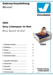
Gebrauchsanleitung<br />
Manual<br />
Bahnschranke<br />
vollautomatisch, mit Zubehör<br />
Automatic Crossing Barrier<br />
with accessories<br />
H0: 5100<br />
TT: 5700<br />
N: 5900<br />
1. Wichtige Hinweise ...................................... 2<br />
2. Einleitung ................................................... 2<br />
3. Inhalt .......................................................... 3<br />
4. Funktionskontrolle ...................................... 4<br />
5. Montage ..................................................... 5<br />
6. Anschluss ................................................... 6<br />
7. Digitale Ansteuerung .................................. 6<br />
8 Montage der Verkehrsschilder .................... 8<br />
9. Technische Daten ...................................... 8<br />
5100<br />
1. Important Information ................................. 2<br />
2. Introduction ................................................ 2<br />
3. Content ...................................................... 3<br />
4. Function Check .......................................... 4<br />
5. Mounting ..................................................... 5<br />
6. Connections ............................................... 6<br />
7. Digital Control ............................................ 6<br />
8. Installing the traffic signs ............................ 8<br />
9. Technical Data ........................................... 8
DE<br />
1. Wichtige Hinweise<br />
Lesen Sie vor der ersten Benutzung des Produktes<br />
bzw. dessen Einbau diese Anleitung komplett<br />
und aufmerksam durch. Bewahren Sie diese Anleitung<br />
auf. Sie ist Teil des Produktes.<br />
Das Produkt richtig verwenden<br />
Das Produkt darf ausschließlich dieser Anleitung<br />
gemäß verwendet werden. Dieses Modell<br />
ist bestimmt<br />
• zum Einbau in Modelleisenbahnanlagen und<br />
Dioramen<br />
• zum Anschluss an einen zugelassenen Modellbahntransformator<br />
bzw. an einer damit<br />
versorgten elektrischen Steuerung<br />
• zum Betrieb in trockenen Räumen.<br />
Jeder darüber hinausgehende Gebrauch gilt als<br />
nicht bestimmungsgemäß. Für daraus resultierende<br />
Schäden haftet der Hersteller nicht.<br />
2. Einleitung<br />
Vorbild<br />
Zur Sicherung von Bahnübergängen durch<br />
Schrankenwärter wurden früher wie heute Bahnschranken<br />
verwendet. Diese Schranken wurden<br />
über Seilzüge durch den Schrankenwärter fernbedient.<br />
Bis in die heutige Zeit haben sich diese<br />
Bahnübergänge beim Vorbild halten können, allerdings<br />
werden es immer weniger, da alle handbetätigten<br />
Bahnübergänge nach und nach durch moderne<br />
Lichtzeichenanlagen ersetzt werden.<br />
Modell<br />
Das <strong>Viessmann</strong>-Modell einer Bahnschranke gibt<br />
die Vorbildsituation vorbildgerecht wieder und ist<br />
ein Schmuckstück auf jeder Anlage. Die beiden<br />
Schrankenbäume werden durch je einen Unterflur-Kompaktantrieb<br />
angetrieben, welche diese<br />
vorbildgerecht langsam heben und senken.<br />
Da jeder Schrankenbaum einzeln angetrieben<br />
wird, kann die Schranke freizügig eingesetzt und<br />
jeder Betriebssituation angepasst werden. Übergänge<br />
im Winkel von 45°, mehrgleisige Übergänge<br />
oder der Einsatz von vier Schrankenbäumen<br />
als gegenschlägige Schranke für sehr breite Straßen<br />
sind kein Problem (Widerlager sind nicht notwendig,<br />
Schrankenbäume stehen ohne Stütze in<br />
der Endlage waagerecht).<br />
Ein Gleisfüllstück sowie Rampen auf das Gleisniveau<br />
liegen bei.<br />
EN<br />
1. Important Information<br />
Please read this manual prior to first use of the<br />
product resp. its installation! Keep this manual. It<br />
is part of the product.<br />
Using the product for it’s correct<br />
purpose<br />
This product must only be used as required in<br />
this manual. This model is intended<br />
• for installation in model railroad layouts and<br />
dioramas,<br />
• for connection to an authorized model railroad<br />
transformer or an electrical control system<br />
connected to one<br />
• for operation in a dry area.<br />
Using the product for any other purpose is not<br />
approved and is considered incorrect.<br />
The manufacturer cannot be held responsible<br />
for any damage resulting from the improper use<br />
of this product.<br />
2. Introduction<br />
Prototype<br />
Today, as in the past, attendants use railroad<br />
gates to secure railroad crossings. These gates<br />
are operated remotely by the attendants via cables.<br />
These railroad crossings have kept their<br />
original appearance to this very day, although<br />
there are fewer today because manually operated<br />
railroad crossings have been replaced by modern<br />
flashing light systems.<br />
The Model<br />
The <strong>Viessmann</strong> model of a railroad crossing gate<br />
is a true representation of the actual situation and<br />
is an enrichment to any model layout.<br />
Driven by a compact drive installed underneath<br />
each cross beam, the cross beams rise and lower<br />
at a representative slow speed.<br />
Because each cross beam is driven individually,<br />
the gate can be installed as desired and adapted<br />
to any operating situation. Crossings at an angle<br />
of 45°, multiple-track crossings, or the use of four<br />
cross beams across from each other as a gate for<br />
very wide streets is no problem (rests are not necessary,<br />
the cross beams remain horizontal in the<br />
end position without support).<br />
A track filler piece as well as ramps for the track<br />
level are included.<br />
2
Die beiliegenden Verkehrsschilder sind bereits fertig<br />
bedruckt. Für den Einsatz der Schranke in den<br />
Epochen II - III sind an den Andreaskreuzen und<br />
den Warnbaken Bruchkanten angebracht, um<br />
diese den damaligen Straßenverkehrsvorschriften<br />
entsprechend kürzen zu können.<br />
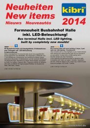
3. Inhalt<br />
Das Schrankenset besteht aus den in der folgenden<br />
Tabelle aufgeführten Teilen. Bitte prüfen<br />
Sie vor dem Einbau, ob der Verpackungsinhalt<br />
vollständig ist.<br />
The included traffic signs are already printed.<br />
Breaking edges are provided on the St. Andrew’s<br />
crosses and the warning signs, so that is possible<br />
to shorten the signs appropriately to fit the traffic<br />
regulations of periods II - III.<br />
3. Contents<br />
Check the contents of the package before assembly<br />
to ensure that is complete! The following parts<br />
are included in the package:<br />
Pos. Bezeichnung / Item H0 TT N<br />
1 Bahnschranke mit Antrieb / Barrier with drive unit 2 2 2<br />
2 Verkehrsschild mit Mast / Traffic sign with pole 2 2 2<br />
3 Andreaskreuz mit Mast / St.Andrew‘s cross with pole 2 2 2<br />
4 Warnbaken mit Mast / Warning sign with pole 12 12 12<br />
5 Rampe / Ramp 2 4 2<br />
6 Rampenfuß / Ramp foot 4 - -<br />
7 Gleiszwischenstück / 1 1 1<br />
8 Gleiszwischenstück mit Kabel / 1 - -<br />
9 Befestigungsring für Antrieb / Attachment ring for drive 2 2 2<br />
10 Schrankenbaumwiderlager / Cross beam rest 2 2 2<br />
11 Oberes Sockelstück für Widerlager / Upper socket for rest 2 - -<br />
12 Unteres Sockelstück für Widerlager / Lower socket for rest 2 - -<br />
13 Oberes Sockelstück für Schranke / Upper socket for barrier 2 - -<br />
14 Unteres Sockelstück für Schranke / Lower socket for barrier 2 - -<br />
Abb. 1<br />
11<br />
Fig. 1<br />
12<br />
5<br />
1<br />
10<br />
7<br />
10<br />
11<br />
12<br />
1<br />
13<br />
5<br />
14<br />
13<br />
6<br />
8<br />
5100<br />
14<br />
3
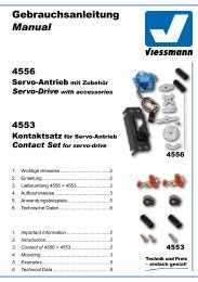
Abb. 2<br />
Fig. 2<br />
Achtung:<br />
Fassen Sie die Schranken<br />
nie am Baum oder<br />
Lager an, sondern nur<br />
an der Bodenplatte bzw.<br />
dem Antriebszylinder!<br />
Attention:<br />
Never touch the barrier<br />
itself. If you have to unmount<br />
the model, don’t<br />
pull the model. Carefully<br />
take the drive unit instead<br />
and push it up.<br />
90°<br />
4. Funktionskontrolle<br />
Nehmen Sie die Bahnschranken vorsichtig aus<br />
der Verpackung. Führen Sie vor der Montage eine<br />
Funktionskontrolle durch.<br />
Schließen Sie dazu das gelbe Kabel an einem<br />
Pol eines 16 V-Modellbahntransformators – z. B.<br />
<strong>Viessmann</strong> 5200 – an.<br />
Verbinden Sie abwechselnd jeweils ein blaues<br />
Kabel mit dem anderen Pol des Trafos. Schließen<br />
Sie niemals die blauen Kabel gleichzeitig an.<br />
Das kann zur Zerstörung des Antriebs führen.<br />
Blau mit roter Markierung:<br />
Schranken öffnen sich.<br />
Blau mit grüner Markierung:<br />
Schranken schließen sich.<br />
4. Checking the Function<br />
Remove the model from the box carefully. Check<br />
all functions prior to installation.<br />
Connect the yellow wire to one of the terminals<br />
of a 16 V transformer (AC/DC) e. g. <strong>Viessmann</strong><br />
5200.<br />
Then alternately connect the blue cables with the<br />
other terminal, but only briefly. Never connect<br />
the blue cables at the same time to the transformer.<br />
This may destroy the drive unit.<br />
Blue with red marker:<br />
Crossing gates open<br />
Blue with green marker:<br />
Crossing gates close<br />
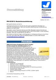
Abb. 3<br />
Fig. 3<br />
blau mit roter Markierung<br />
blue with red marking<br />
blau mit grüner Markierung<br />
blue with green marking<br />
gelb<br />
yellow<br />
Schranke öffnen<br />
open crossing gate<br />
Schranke schließen<br />
close crossing gate<br />
gemeinsamer Mittelpunkt der Antriebsspulen<br />
common pole for the drive coils<br />
5100<br />
5100<br />
rot<br />
red<br />
rot<br />
red<br />
Kontakt für Blinkelektronik der Andreaskreuze<br />
contact for blinking unit etc.<br />
Kontakt für Blinkelektronik der Andreaskreuze<br />
contact for blinking unit etc.<br />
4
5. Montage<br />
1. Zeichnen Sie die Positionen der Bohrungen<br />
für die Schranken und die Widerlager mit<br />
Hilfe der in Abb. 4 abgebildeten Schablone an.<br />
Die Mittelpunkte der Bohrungen müssen einen<br />
Abstand von 46 mm (H0), 58,6 mm (TT) bzw.<br />
50 mm (N) haben.<br />
2. Bohren Sie an den angezeichneten Stellen jeweils<br />
zwei Löcher mit einem Durchmesser von<br />
13 mm für die Schrankenantriebe und 4 mm<br />
(H0) bzw. 1 mm (TT, N) für die Widerlager.<br />
3. Stecken Sie die Schranken mit dem Antrieb<br />
von oben durch die Bohrungen.<br />
4. Schieben Sie die Befestigungsringe von unten<br />
so auf die Antriebe auf, dass die Rastnasen<br />
um 90° zu der Riffelung am Gehäuse der Antriebe<br />
verdreht sind (Abb. 2). Drehen Sie den<br />
Ring so, dass die Nasen in der Riffelung des<br />
Antriebsgehäuses für einen festen Halt sorgen.<br />
Hierbei sollten Sie die Sockel der Bahnschranke<br />
von oben festhalten.<br />
5. Stecken Sie die Widerlager in die entsprechenden<br />
Bohrungen ein.<br />
6. Kleben Sie das Gleisfüllstück bzw. auf die<br />
Schwellen zwischen den Schienenprofilen im<br />
Bereich des Bahnüberganges auf.<br />
Bei Zweileitergleisen (Fleischmann, Trix,<br />
Roco, Peco, Lima usw.) verwenden Sie bitte<br />
das Gleiszwischenstück ohne Metallstreifen<br />
und Anschlusskabel.<br />
Für Mittelleitergleise (nur H0: Märklin C, M<br />
und K, Trix Express) verwenden Sie bitte das<br />
Gleiszwischenstück mit Metallstreifen und<br />
rotem Anschlusskabel. Das rote Anschlusskabel<br />
führen Sie zwischen den Schwellen nach<br />
unten (eventuell zuvor ein Loch bohren) und<br />
schließen es am Mittelleiter-Fahrstromanschluss<br />
(rot bei Märklin) an.<br />
Zum Erstellen breiterer oder mehrgleisiger Übergänge<br />
für H0 gibt es unter der Art.-Nr. 5101 (Zweileiter)<br />
und Art.-Nr. 5102 (Mittelleiter) einen Ergänzungssatz<br />
mit jeweils einem entsprechenden<br />
Gleiszwischenstück. Die Rampen dienen als<br />
Auffahrt für die Modellautos auf das Gleisniveau.<br />
5. Mounting<br />
1. Mark the positions for the holes to be drilled for<br />
the gates and the rests using the pattern<br />
printed on the right side. The center points of<br />
the holes must be 46 mm (H0), 58,6 mm (TT)<br />
or 50 mm (N) from each other.<br />
2. Drill two holes for each gate at the marked positions<br />
with a diameter of 13 mm (for the gates)<br />
and 4 mm (H0) resp. 1 mm (TT, N) for the<br />
rests.<br />
3. Insert the gates with the drive from above<br />
through the large holes.<br />
4. Place the attachment rings on to the drives<br />
so that the catches are at a 90° angle to the<br />
ridges on the housing of the drives (Fig. 2).<br />
When the four plastic straps of the attachment<br />
ring are mechanically clamped to the layout<br />
board, turn the ring so that the catches provide<br />
a firm hold in the ridges of the drive housing.<br />
You should hold the base of the railroad gate<br />
while doing so.<br />
5. Insert the rests into the smaller holes.<br />
6. Glue the track filling piece resp. on the<br />
ties between the tracks in the area of the railroad<br />
crossing.<br />
For two-rail-tracks (Fleischmann, Trix, Roco,<br />
Peco, Lima, ...) please use the track filling<br />
piece 7 without metalstripe and without wire.<br />
For three-railtracks (only H0: Märklin C, M<br />
and K, Trix Express), please use the track filling<br />
piece 8 with metal-stripe and with red wire.<br />
The red connecting wire has to go between the<br />
sleepers to the lower side of the layout (first<br />
drill a hole). Then connect it to the third-rail-current<br />
(Märklin: red).<br />
To build railroad gate with more than one track,<br />
we offer for H0 the completition-sets 5101 (tworailtracks)<br />
and 5102 (three-rail-tracks). Both of<br />
them are including another track filling piece.<br />
The ramps allow model automobiles to reach<br />
track level.<br />
Abb. 4<br />
TT: 58,6 mm<br />
N: 50 mm<br />
H0: 46 mm<br />
Widerlager<br />
rest<br />
H0: 4 mm<br />
13 mm Schranke<br />
H0: 5 mm 11 N + TT: 1 mm<br />
railroad gate H0: 5,5 mm 12<br />
Fig. 4<br />
13 mm<br />
5
6. Anschluss<br />
Alle Anschluss- und Montagearbeiten dürfen<br />
nur bei abgeschalteter Betriebsspannung<br />
durchgeführt werden!<br />
Verwenden Sie nur nach VDE /EN-gefertigte<br />
Modellbahntransformatoren!<br />
Sichern Sie die Stromquellen unbedingt so<br />
ab, dass es bei einem Kurzschluss nicht<br />
zum Kabelbrand kommen kann.<br />
Die Betriebsspannung beträgt 16 V ~.<br />
Schließen Sie die Schranken gemäß Abb. 5 oder<br />
6 an. Zur Bedeutung der Kabelfarben siehe Abb.<br />
3. Für den zuggesteuerten Betrieb benötigen Sie<br />
Schaltgleise oder -Kontakte (z. B. 6840 & 6841).<br />
Bei zweigleisigem Betrieb ist ein elektronisches<br />
Relais 5552 erforderlich. Dadurch wird erreicht,<br />
dass bei gleichzeitigem Überqueren des Bahnüberganges<br />
von zwei entgegenkommenden Zügen<br />
die Schranken erst wieder geöffnet werden, wenn<br />
beide Züge den Bahnübergang verlassen haben.<br />
Die Antriebe der H0-Bahnschranke (5100) verfügen<br />
über jeweils einen zusätzlichen Schaltkontakt.<br />
Dieser können Sie nutzen, um z. B. eine Blinkelektronik<br />
für Andreaskreuze (z. B. 5835) zu steuern.<br />
Hierzu führen Sie eine der beiden Stromversorgungsleitungen<br />
der Blinkelektronik über den<br />
Kontakt eines der beiden Antriebe.<br />
Gleichstrombetrieb: Schließen Sie die gelben<br />
Kabel an den Minuspol des Trafos an.<br />
7. Digitale Ansteuerung<br />
Die <strong>Viessmann</strong> Bahnschranken lassen sich ohne<br />
Probleme auch mit einem Digitalsystem ansteuern.<br />
Schließen Sie die Antriebe der Bahnschranken<br />
dazu an einen Magnetartikeldecoder z. B.<br />
den 5211 (Märklin-Motorola) oder 5212 (DCC) wie<br />
eine Weiche oder ein Signal an. Achten Sie darauf,<br />
neben den blauen auch das gelbe Kabel für<br />
die Stromversorgung anzuschließen.<br />
Hinweis für digitales Schalten<br />
Der <strong>Viessmann</strong> Universalantrieb benötigt für<br />
den ordnungsgemäßen Betrieb eine Schaltspannung<br />
von mindestens 16 Volt.<br />
Verwenden Sie ausschließlich Magnetartikeldecoder<br />
mit separater Schaltspannungseinspeisung<br />
(z. B. alle <strong>Viessmann</strong> Magnetartikeldecoder)<br />
und einen ausreichend starken<br />
Trafo (z. B. <strong>Viessmann</strong> 5200 oder 5201,<br />
vorzugsweise in Verbindung mit dem <strong>Viessmann</strong><br />
Powermodul 5215).<br />
6. Connections<br />
Make sure that the power supply is switched<br />
off when you mount the device and connect<br />
the wires!<br />
Only use VDE/EN tested special model train<br />
transformers for the power supply!<br />
The power sources must be protected to<br />
prevent the risk of burning wires.<br />
The operating voltage is 16 V AC.<br />
Now make the electrical connection as per figure<br />
5 or 6. For the meaning of the cable colours refer<br />
to figure 3. To control the gates by trains, you<br />
need switching tracks or -contacts (e. g. <strong>Viessmann</strong><br />
track contact for H0 6840 & 6841)<br />
An electronic relay 5552 is required for two-track<br />
operation. This is necessary so that when two<br />
trains approaching each other cross the railroad<br />
crossing at the same time, the beams do not open<br />
until both trains have left the crossing.<br />
The drive units of the H0-railroad crossing gates<br />
(5100) are including an additional switching contact.<br />
This can be used to control the blinking electronics<br />
of warning lights (e. g. 5835). To use this<br />
function, please connect one of the wires for the<br />
electric current of the blinking electronic with the<br />
contact of one of the drive units.<br />
Direct current: Connect both yellow cables to the<br />
negative pole of the transfomer.<br />
7. Digital Control<br />
The <strong>Viessmann</strong> railroad crossing gates can be<br />
controlled without problems using a digital system.<br />
For digital control of the gates, connect the drive<br />
units to an accessory decoder such as the 5211<br />
(Märklin-Motorola) or 5212 (DDC) in the same<br />
way as a turnout or a signal. Remind, that you<br />
have to connect not only the blue cables but also<br />
the yellow cables for power supply!<br />
Important information<br />
for digital switching<br />
The <strong>Viessmann</strong> universal drive requires a<br />
switching voltage of minimum 16 Volt for<br />
proper operation.<br />
Therefore you should use accessory decoders<br />
with a separate switching voltage input<br />
only (e. g. all <strong>Viessmann</strong> decoders).<br />
For power supply, use a powerful transformer<br />
(e g. <strong>Viessmann</strong> 5200 or 5201) combined<br />
with the <strong>Viessmann</strong> power module 5215.<br />
6
Abb. 5<br />
blau (grüne Markierung) / blue (green marker)<br />
mind. 1 Zuglänge<br />
grün / green<br />
min. 1 train length<br />
Fig. 5<br />
öffnen<br />
open<br />
schließen<br />
close<br />
Fahrtrichtung<br />
schließen<br />
close<br />
öffnen<br />
open<br />
rot / red<br />
blau (rote Markierung) / blue (red marker)<br />
gelb / yellow<br />
braun / brown<br />
16 V ~<br />
Das nebenstehende Symbol kennzeichnet<br />
eine Leitungsverbindung. Die sich hier<br />
kreuzenden Leitungen müssen an einer<br />
beliebigen Stelle ihres Verlaufs elektrisch leitend<br />
miteinander in Verbindung stehen.<br />
The symbol left designates a cable connection.<br />
The cables that cross here must<br />
be in electrical contact with each other at<br />
some point along their length.<br />
Abb. 6<br />
blau (rote Markierung) / blue (red marker)<br />
Fig. 6<br />
öffnen<br />
open<br />
mind. 1 Zuglänge<br />
min. 1 train length<br />
grün/ green<br />
schließen<br />
close<br />
Fahrtrichtung<br />
schließen<br />
close<br />
öffnen<br />
open<br />
Fahrtrichtung<br />
rot / red<br />
blau<br />
blue<br />
blau (grüne Markierung) / blue (green marker)<br />
blau<br />
blue<br />
braun<br />
brown<br />
16 V ~<br />
gelb / yellow<br />
blau<br />
blue<br />
Elektr. Relais 5552<br />
<strong>Viessmann</strong><br />
blau<br />
blue<br />
blau<br />
blue<br />
blau<br />
blue<br />
Schranke auf<br />
open barrier<br />
Schranke zu<br />
close barrier<br />
7
8. Montage der Verkehrsschilder<br />
1. Zur Verwendung der Schilder in den Epochen II und<br />
III die Warnbaken und die Andreaskreuze an<br />
den vorgegebenen Bruchkanten auf der Rückseite<br />
der Schilder kürzen. Mit scharfem Messer vorritzen!<br />
2. Andreaskreuze (bei H0 auch die Warnbaken)<br />
mit handelsüblichem Polystyrolkleber an die entspr.<br />
Masten kleben. Beachten Sie hierbei, dass<br />
in den Epochen II und III das Andreaskreuz <br />
um 90° gedreht am Mast befestigt wurde, wobei<br />
die kurzen Schenkel nach unten zeigten.<br />
3. Bohren Sie an den dafür vorgesehenen Stellen<br />
Löcher mit dem in der Abbildung angegebenen<br />
Durchmesser und montieren Sie die Schilder in<br />
der richtigen Reihenfolge (siehe Abb. 7)<br />
4. Der Regelabstand zwischen den Warnbaken beträgt<br />
beim Vorbild 80 m (H0: 92 cm, TT: 67 cm,<br />
N: 50 cm). Wenn die örtlichen Gegebenheiten es<br />
erfordern, sind aber auch kürzere Abstände erlaubt.<br />
5. Bei beengten Platzverhältnissen können Sie<br />
die dreistreifige Warnbake mit einem Messer<br />
vom eigenen Mast abtrennen und unten an den<br />
Mast des Verkehrsschildes kleben.<br />
Abb. 7<br />
H0:<br />
4 mm<br />
3<br />
8. Installing the traffic signs<br />
1. To use the signs in periods II and III, first shorten<br />
the warning sign and the St. Andrew’s<br />
crosses at the specified breaking edges on<br />
the rear of the signs. If necessary, first cut an<br />
indentation with a sharp knife!<br />
2. Glue the Andrew’s crosses with standard polystyrene<br />
glue to their respective poles. Please<br />
note that in periods II and III the St. Andrew’s<br />
cross was attached at a 90° angle on the<br />
pole, with the short shanks pointing downwards.<br />
3. Drill holes with the diameter shown in Fig. 7 at<br />
the positions desired and install the signs in the<br />
correct sequence (see Figure 7).<br />
4. The standard distance between the warning<br />
signs in reality is 80 m (H0: 92 cm, TT: 67 cm,<br />
N: 50 cm). Shorter distances are also permitted<br />
when the local situation requires it.<br />
5. If space is tight, you can also remove the warning<br />
sign with three stripes from its pole using<br />
a knife and glue it at the bottom on the pole of<br />
the traffic sign .<br />
zum Bahnübergang<br />
to the railroad crossing<br />
4 4<br />
4<br />
2<br />
Fig. 7<br />
TT, N:<br />
1,5 mm<br />
9. Technische Daten<br />
Betriebsspannung: 16 V ~<br />
Stromaufnahme<br />
(im Schaltmoment, ca. 0,03 s): 2 x 0,7 A<br />
6. Technical Data<br />
Operating voltage:<br />
16 V AC<br />
Peak inrush current (for approx. 0.03 s): 2 x 0.7 A<br />
8<br />
Dekoartikel, kein Spielzeug! Nicht geeignet für Kinder unter 14<br />
Jahren! Maßstabsgetreues Modell zur Dekoration einer Modell-<br />
Landschaft. Produkt kann Spitzen, Kanten und abbruchgefährdete<br />
Teile aufweisen. Verletzungsgefahr! Die Anschlussdrähte niemals in<br />
eine Steckdose einführen! Anleitung aufbewahren!<br />
Decoration item, not a toy! Not suitable for children under 14<br />
years! True to scale model for the decoration of a model landscape.<br />
This product can have peaks, edges and breakable parts. Risk of<br />
injury! Never put the connecting wires into a power socket! Keep<br />
these instructions!<br />
Ce produit n’est pas un jouet. C’est un produit décor! Ne<br />
convient pas aux enfants de moins de 14 ans ! Modèle réduit fidèle<br />
à l’échelle pour la décoration d’un réseau. Le produit peut présenter<br />
des pointes, des arêtes et des pièces détachables. Risque de<br />
<strong>Modellspielwaren</strong> <strong>GmbH</strong><br />
blessure! Ne jamais introduire les fils d’alimentation dans une prise!<br />
Conservez ce mode d’emploi!<br />
Decoratie artikel, geen speelgoed! Niet geschikt voor kinderen onder<br />
14 jaar! Schaalmodel, bedoeld als decoratie model in een modellandschap.<br />
Kunnen er onderdelen met scherpe punten, zijkanten en ook breekbare<br />
onderdelen aanwezig zijn. Risico op verwonding! De aansluitdraden<br />
nooit in een wandcontactdoos steken! Gebruiksaanwijzing bewaren!<br />
Articolo decorativo, non è un giocattolo! Non adatto a bambini<br />
al di sotto dei 14 anni! Modello in scala per la decorazione di un<br />
paesaggio per modellismo. Il prodotto può presentare punte, spigoli<br />
e parti che potrebbero staccarsi. Pericolo di lesion! Non inserire mai<br />
i fili di collegamento in una presa! Conservare instruzioni per l’uso!<br />
Artículo para decoración ¡No es un juguete! No recomendado para<br />
menores de 14 años! Este producto es un modelo en miniatura para<br />
decorar un paisaje en una maqueta. Los modelos pueden tener partes<br />
puntiagudas, cantos y piezas filigranas. Riesgo a lesionarse. ¡No introducir<br />
nunca los hilos de conexiones en un enchufe de la red eléctrica!<br />
Conserva las instrucciones de servicio!<br />
12/2011 Ko<br />
Stand 05<br />
Sach-Nr. 98179<br />
Made in Europe

![Interactive News [pdf]](https://img.yumpu.com/13782861/1/190x107/interactive-news-pdf.jpg?quality=85)
