IEA Solar Heating and Cooling Programm - NachhaltigWirtschaften.at
IEA Solar Heating and Cooling Programm - NachhaltigWirtschaften.at IEA Solar Heating and Cooling Programm - NachhaltigWirtschaften.at
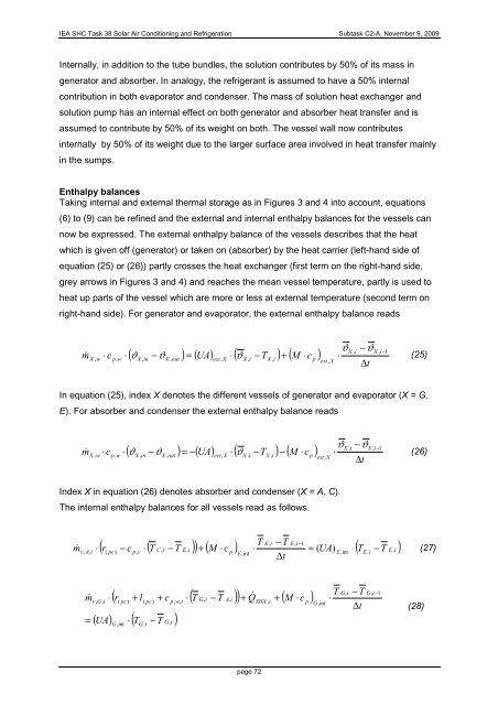
IEA SHC Task 38 Solar Air Conditioning and Refrigeration Subtask C2-A, November 9, 2009 Internally, in addition to the tube bundles, the solution contributes by 50% of its mass in generator and absorber. In analogy, the refrigerant is assumed to have a 50% internal contribution in both evaporator and condenser. The mass of solution heat exchanger and solution pump has an internal effect on both generator and absorber heat transfer and is assumed to contribute by 50% of its weight on both. The vessel wall now contributes internally by 50% of its weight due to the larger surface area involved in heat transfer mainly in the sumps. Enthalpy balances Taking internal and external thermal storage as in Figures 3 and 4 into account, equations (6) to (9) can be refined and the external and internal enthalpy balances for the vessels can now be expressed. The external enthalpy balance of the vessels describes that the heat which is given off (generator) or taken on (absorber) by the heat carrier (left-hand side of equation (25) or (26)) partly crosses the heat exchanger (first term on the right-hand side, grey arrows in Figures 3 and 4) and reaches the mean vessel temperature, partly is used to heat up parts of the vessel which are more or less at external temperature (second term on right-hand side). For generator and evaporator, the external enthalpy balance reads ϑX , i −ϑX , i−1 m& X , w ⋅ c p, w ⋅ ( ϑX , in −ϑX , out ) = ( UA) ext, X ⋅ ( ϑ X , i − TX , i ) + ( M ⋅ c p ) ⋅ (25) ext, X ∆t In equation (25), index X denotes the different vessels of generator and evaporator (X = G, E). For absorber and condenser the external enthalpy balance reads ϑX , i −ϑX , i−1 m& X , w ⋅ c p, w ⋅( ϑX , in −ϑX , out ) = −( UA) ext, X ⋅ ( ϑX , i −TX , i ) − ( M ⋅c p ) ⋅ (26) ext, X ∆t Index X in equation (26) denotes absorber and condenser (X = A, C). The internal enthalpy balances for all vessels read as follows. T E, i − T E, i−1 ( r − c ⋅ ( T C, i − T E, i ) + ( M ⋅ c ) ⋅ = ( UA ⋅ ( T − T E i ) & (27) ∆t m v, A, i ⋅ ( pc) p, v p ) E E,int E, i , ,int m& = v, G, i ⋅ ( r( pc) + l( pc) + c p, w, i ⋅ ( T G, i − T A, i ) + Q& SHX , i + ( M ⋅ c p ) ( UA) ⋅ ( T − T G, i ) G,int G, i G,int T ⋅ G, i − T ∆t G, i−1 (28) page 72
IEA SHC Task 38 Solar Air Conditioning and Refrigeration Subtask C2-A, November 9, 2009 T C, i − T C, i−1 ( r + c ⋅ ( T G, i − T C, i ) + ( M ⋅ c ) ⋅ = ( UA) ⋅ ( T T ) & (29) ∆t m v, G, i ⋅ ( pc) p, v p C,int C,int C, i − C, i m& v, A, i ⋅ ( r + l − c ⋅ ( T G, i − T E, i ) + c ⋅ ( T G, i − T A, i ) ( pc) T A, i − T A, i−1 ( M ⋅ c ) ⋅ = ( UA) ⋅ ( T − T ) p A,int ( pc) ∆t p, v A,int p, w A, i A, i + Q& SHX , i + (30) Equations (27) and (28) describe the internal heat transfer in evaporator and generator, respectively. There, the heat which is given off by the heat exchanger (right-hand side) partly heats up the internal parts of the vessel (second term on left-hand side) and partly is used for the heating of solution and refrigerant (first term on left-hand side). In analogy, equations (29) and (30) describe condenser and absorber, respectively. There, the heat which is given off by the solution and refrigerant (first term on left-hand side) is used partly to heat the internal parts of the heat exchanger (second term on left-hand side) and partly to heat the cooling water (right-hand side). The equation system is being solved in MATLAB using a Newton-Raphson procedure with finite-difference Jacobian approximation [6]. Experimental Verification The agreement between simulated and experimental data has been tested using an experimentally measured hot water input step from 75 to 85 °C. The results of the simulation using these input data are shown in Figure 5. The hot water inlet and outlet temperatures in Figure 5 are taken from experimental measurements of the Phoenix absorption chiller. They show the transient behaviour of the chiller for a 10K step in hot water inlet temperature. Cooling and chilled water inlet temperatures as well as all external mass flow rates were kept constant during the step. It can be seen that it takes approx. 600s or 10 minutes to achieve a new steady-state in hot water inlet temperature after the step. This is shorter than the 15 minutes it takes for all parameters to achieve steady-state again. The simulation was performed using the measured data as inputs in the model and comparing simulated and measured hot water outlet temperatures. page 73
- Page 498 and 499: IEA SHC Task 38 Solar Air Condition
- Page 500 and 501: IEA SHC Task 38 Solar Air Condition
- Page 502 and 503: IEA SHC Task 38 Solar Air Condition
- Page 504 and 505: IEA SHC Task 38 Solar Air Condition
- Page 506 and 507: IEA SHC Task 38 Solar Air Condition
- Page 508 and 509: IEA SHC Task 38 Solar Air Condition
- Page 510 and 511: IEA SHC Task 38 Solar Air Condition
- Page 512 and 513: IEA SHC Task 38 Solar Air Condition
- Page 514 and 515: IEA SHC Task 38 Solar Air Condition
- Page 516 and 517: IEA SHC Task 38 Solar Air Condition
- Page 518 and 519: IEA SHC Task 38 Solar Air Condition
- Page 520 and 521: IEA SHC Task 38 Solar Air Condition
- Page 522 and 523: IEA SHC Task 38 Solar Air Condition
- Page 524 and 525: IEA SHC Task 38 Solar Air Condition
- Page 526 and 527: IEA SHC Task 38 Solar Air Condition
- Page 528 and 529: IEA SHC Task 38 Solar Air Condition
- Page 530 and 531: IEA SHC Task 38 Solar Air Condition
- Page 532 and 533: IEA SHC Task 38 Solar Air Condition
- Page 534 and 535: IEA SHC Task 38 Solar Air Condition
- Page 536 and 537: IEA SHC Task 38 Solar Air Condition
- Page 538 and 539: IEA SHC Task 38 Solar Air Condition
- Page 540 and 541: IEA SHC Task 38 Solar Air Condition
- Page 542 and 543: IEA SHC Task 38 Solar Air Condition
- Page 544 and 545: IEA SHC Task 38 Solar Air Condition
- Page 546 and 547: IEA SHC Task 38 Solar Air Condition
- Page 550 and 551: IEA SHC Task 38 Solar Air Condition
- Page 552 and 553: IEA SHC Task 38 Solar Air Condition
- Page 554 and 555: IEA SHC Task 38 Solar Air Condition
- Page 556 and 557: IEA SHC Task 38 Solar Air Condition
- Page 558 and 559: IEA SHC Task 38 Solar Air Condition
- Page 560 and 561: IEA SHC Task 38 Solar Air Condition
- Page 562 and 563: IEA SHC Task 38 Solar Air Condition
- Page 564 and 565: IEA SHC Task 38 Solar Air Condition
- Page 566 and 567: IEA SHC Task 38 Solar Air Condition
- Page 568 and 569: IEA SHC Task 38 Solar Air Condition
- Page 570 and 571: IEA SHC Task 38 Solar Air Condition
- Page 572 and 573: Task 38 Solar Air-Conditioning and
- Page 574 and 575: IEA SHC Task 38 Solar Air Condition
- Page 576 and 577: IEA SHC Task 38 Solar Air Condition
- Page 578 and 579: IEA SHC Task 38 Solar Air Condition
- Page 580 and 581: IEA SHC Task 38 Solar Air Condition
- Page 582 and 583: IEA SHC Task 38 Solar Air Condition
- Page 584 and 585: IEA SHC Task 38 Solar Air Condition
- Page 586 and 587: IEA SHC Task 38 Solar Air Condition
- Page 588 and 589: IEA SHC Task 38 Solar Air Condition
- Page 590 and 591: IEA SHC Task 38 Solar Air Condition
- Page 592 and 593: IEA SHC Task 38 Solar Air Condition
- Page 594 and 595: IEA SHC Task 38 Solar Air Condition
- Page 596 and 597: IEA SHC Task 38 Solar Air Condition
<strong>IEA</strong> SHC Task 38 <strong>Solar</strong> Air Conditioning <strong>and</strong> Refriger<strong>at</strong>ion Subtask C2-A, November 9, 2009<br />
Internally, in addition to the tube bundles, the solution contributes by 50% of its mass in<br />
gener<strong>at</strong>or <strong>and</strong> absorber. In analogy, the refrigerant is assumed to have a 50% internal<br />
contribution in both evapor<strong>at</strong>or <strong>and</strong> condenser. The mass of solution he<strong>at</strong> exchanger <strong>and</strong><br />
solution pump has an internal effect on both gener<strong>at</strong>or <strong>and</strong> absorber he<strong>at</strong> transfer <strong>and</strong> is<br />
assumed to contribute by 50% of its weight on both. The vessel wall now contributes<br />
internally by 50% of its weight due to the larger surface area involved in he<strong>at</strong> transfer mainly<br />
in the sumps.<br />
Enthalpy balances<br />
Taking internal <strong>and</strong> external thermal storage as in Figures 3 <strong>and</strong> 4 into account, equ<strong>at</strong>ions<br />
(6) to (9) can be refined <strong>and</strong> the external <strong>and</strong> internal enthalpy balances for the vessels can<br />
now be expressed. The external enthalpy balance of the vessels describes th<strong>at</strong> the he<strong>at</strong><br />
which is given off (gener<strong>at</strong>or) or taken on (absorber) by the he<strong>at</strong> carrier (left-h<strong>and</strong> side of<br />
equ<strong>at</strong>ion (25) or (26)) partly crosses the he<strong>at</strong> exchanger (first term on the right-h<strong>and</strong> side,<br />
grey arrows in Figures 3 <strong>and</strong> 4) <strong>and</strong> reaches the mean vessel temper<strong>at</strong>ure, partly is used to<br />
he<strong>at</strong> up parts of the vessel which are more or less <strong>at</strong> external temper<strong>at</strong>ure (second term on<br />
right-h<strong>and</strong> side). For gener<strong>at</strong>or <strong>and</strong> evapor<strong>at</strong>or, the external enthalpy balance reads<br />
ϑX<br />
, i<br />
−ϑX<br />
, i−1<br />
m& X , w<br />
⋅ c<br />
p,<br />
w<br />
⋅ ( ϑX<br />
, in<br />
−ϑX<br />
, out<br />
) = ( UA) ext,<br />
X<br />
⋅ ( ϑ<br />
X , i<br />
− TX<br />
, i<br />
) + ( M ⋅ c<br />
p<br />
) ⋅<br />
(25)<br />
ext,<br />
X<br />
∆t<br />
In equ<strong>at</strong>ion (25), index X denotes the different vessels of gener<strong>at</strong>or <strong>and</strong> evapor<strong>at</strong>or (X = G,<br />
E). For absorber <strong>and</strong> condenser the external enthalpy balance reads<br />
ϑX<br />
, i<br />
−ϑX<br />
, i−1<br />
m& X , w<br />
⋅ c<br />
p,<br />
w<br />
⋅( ϑX<br />
, in<br />
−ϑX<br />
, out<br />
) = −( UA) ext,<br />
X<br />
⋅ ( ϑX<br />
, i<br />
−TX<br />
, i<br />
) − ( M ⋅c<br />
p<br />
) ⋅<br />
(26)<br />
ext,<br />
X<br />
∆t<br />
Index X in equ<strong>at</strong>ion (26) denotes absorber <strong>and</strong> condenser (X = A, C).<br />
The internal enthalpy balances for all vessels read as follows.<br />
T E,<br />
i − T E,<br />
i−1<br />
( r − c ⋅ ( T C,<br />
i − T E,<br />
i<br />
) + ( M ⋅ c ) ⋅<br />
= ( UA ⋅ ( T − T E i )<br />
& (27)<br />
∆t<br />
m<br />
v, A,<br />
i<br />
⋅<br />
( pc)<br />
p,<br />
v<br />
p<br />
)<br />
E<br />
E,int<br />
E,<br />
i ,<br />
,int<br />
m&<br />
=<br />
v,<br />
G,<br />
i<br />
⋅ ( r(<br />
pc)<br />
+ l(<br />
pc)<br />
+ c<br />
p,<br />
w,<br />
i<br />
⋅ ( T G,<br />
i − T A,<br />
i<br />
) + Q&<br />
SHX , i<br />
+ ( M ⋅ c<br />
p<br />
)<br />
( UA) ⋅ ( T − T G,<br />
i )<br />
G,int<br />
G,<br />
i<br />
G,int<br />
T<br />
⋅<br />
G,<br />
i<br />
− T<br />
∆t<br />
G,<br />
i−1<br />
(28)<br />
page 72


