IEA Solar Heating and Cooling Programm - NachhaltigWirtschaften.at
IEA Solar Heating and Cooling Programm - NachhaltigWirtschaften.at IEA Solar Heating and Cooling Programm - NachhaltigWirtschaften.at
IEA SHC Task 38 Solar Air Conditioning and Refrigeration Subtask A Report A-D3b, Date: December 2010 Dehumidification Heat rejection system Solar thermal Collector type Brand of collector Collector area Tilt angle, orientation Collector fluid Typical operation temperature Configuration Heat storage Cold storage Auxiliary heater Auxiliary heating support Auxiliary chiller and a cooling panel in supply air system and in the cooling panel Wet open evacuated tube with CPC-mirror CPC Star azzurro 60 m 2 aperture area 30°, south water 70 °C driving temperature for chiller operation 3 m 3 water 1 m³ water gas condensing boiler, 28 kW Space heating in winter none System scheme 2 x wet cooling tower AHU, cooling panel 2 x Absorption chiller Gas condensing boiler Ceiling cooling elements System performance Data for complete monitoring period 2009: Radiation sum horizontal 1080 kWh/m² Radiation sum in collector plane 1216 kWh/m² Specific collector yield * 337 kWh/m² (collector output, incl. expenses for freezing protection) Collector efficiency * 21 % * on base of collector output; diminished through heat return to the collector for freezing protection Annual thermal COP of Absorption chiller 1: 0.52 Annual electric COP of Absorption chiller system 1: 4.7 (chiller, heat rejection, collector and hot water driving pump) page 32
IEA SHC Task 38 Solar Air Conditioning and Refrigeration Subtask A Report A-D3b, Date: December 2010 Annual electricity demand collector system only: 75 kWh thermal per kWh el. Solar fraction on total annual heat supply (heating and cooling: approx. 37 % System reliability and overall success of the installation One of the two absorptions chillers was in the complete year 2009 not in operation, caused by a vacuum leakage. The problem could not be solved in the first year due to the insolvency procedure of SK Sonnenklima. The chiller was repaired in 2010 and since end of July 2010, both chillers are in operation. The solar system and chiller no. 1 was working with high reliability in 2009. Some stagnation periods in the collector system were passed without difficulty. The collector yields are a little below expectations, mainly caused through shading (trees and a scaffold in 2009 in front of the building). The high temperature flexibility in the driving circuit of the chiller (operation between 90°C and 60°C driving temperature) allowed often a continuous operation of the chiller for 6 hours or more. The chiller thus meets well the requirements for a solar thermal autonomous operation. Problems occurred: - Pollution in the open heat rejection circuit, caused by dust, pollen etc. This lead often to decreased mass flow and thus high heat rejection temperatures. Consequently, for several operation periods the performance of the chiller was low. The problem was solved through the installation of an automated cleaning procedure in the heat rejection circuit; - A measurement error occurred in the heating season in the mass flow of the gas boiler heating circuit. Thus, the heat input of the boiler could not be calculated accurately, but estimated through assumptions of storage heat losses. Overall success: although in 2009 only one of the two chillers was in operation, this (part) system worked with high reliability. The comfort in the seminar rooms has clearly increased, the users (students and teaches) are very satisfied in general. The solar autonomous operation mode matches well the occupation profile and cooling demand profile. Since 2010, both chillers are in operation and during the first operation period, their driving circuits are connected in series (different chilled water temperatures for supply air dehumidification and chilled ceilings). This mode works reliable, the temperature difference in the solar loop is increased by this measure. Photos Collectors system, installed at the main college building Chilled ceilings One of the supply air systems page 33
- Page 123 and 124: IEA SHC Task 38 Monitoring Procedur
- Page 125 and 126: IEA SHC Task 38 Monitoring Procedur
- Page 127 and 128: IEA SHC Task 38 Monitoring Procedur
- Page 129 and 130: IEA SHC Task 38 Monitoring Procedur
- Page 131 and 132: IEA SHC Task 38 Monitoring Procedur
- Page 133 and 134: IEA SHC Task 38 Monitoring Procedur
- Page 135 and 136: IEA SHC Task 38 Monitoring Procedur
- Page 137 and 138: IEA SHC Task 38 Monitoring Procedur
- Page 139 and 140: IEA SHC Task 38 Monitoring Procedur
- Page 141 and 142: IEA SHC Task 38 Monitoring Procedur
- Page 143 and 144: Task 38 Solar Air-Conditioning and
- Page 145 and 146: IEA SHC Task 38 Solar Air Condition
- Page 147 and 148: IEA SHC Task 38 Solar Air Condition
- Page 149 and 150: IEA SHC Task 38 Solar Air Condition
- Page 151 and 152: IEA SHC Task 38 Solar Air Condition
- Page 153 and 154: IEA SHC Task 38 Solar Air Condition
- Page 155 and 156: IEA SHC Task 38 Solar Air Condition
- Page 157 and 158: IEA SHC Task 38 Solar Air Condition
- Page 159 and 160: IEA SHC Task 38 Solar Air Condition
- Page 161 and 162: IEA SHC Task 38 Solar Air Condition
- Page 163 and 164: IEA SHC Task 38 Solar Air Condition
- Page 165 and 166: IEA SHC Task 38 Solar Air Condition
- Page 167 and 168: IEA SHC Task 38 Solar Air Condition
- Page 169 and 170: IEA SHC Task 38 Solar Air Condition
- Page 171 and 172: IEA SHC Task 38 Solar Air Condition
- Page 173: IEA SHC Task 38 Solar Air Condition
- Page 177 and 178: IEA SHC Task 38 Solar Air Condition
- Page 179 and 180: IEA SHC Task 38 Solar Air Condition
- Page 181 and 182: IEA SHC Task 38 Solar Air Condition
- Page 183 and 184: IEA SHC Task 38 Solar Air Condition
- Page 185 and 186: IEA SHC Task 38 Solar Air Condition
- Page 187 and 188: IEA SHC Task 38 Solar Air Condition
- Page 189 and 190: IEA SHC Task 38 Solar Air Condition
- Page 191 and 192: IEA SHC Task 38 Solar Air Condition
- Page 193 and 194: IEA SHC Task 38 Solar Air Condition
- Page 195 and 196: IEA SHC Task 38 Solar Air Condition
- Page 197 and 198: IEA SHC Task 38 Solar Air Condition
- Page 199 and 200: IEA SHC Task 38 Solar Air Condition
- Page 201 and 202: IEA SHC Task 38 Solar Air Condition
- Page 203 and 204: Task 38 Solar Air-Conditioning and
- Page 205 and 206: IEA SHC Task 38 Solar Air Condition
- Page 207 and 208: IEA SHC Task 38 Solar Air Condition
- Page 209 and 210: IEA SHC Task 38 Solar Air Condition
- Page 211 and 212: IEA SHC Task 38 Solar Air Condition
- Page 213 and 214: IEA SHC Task 38 Solar Air Condition
- Page 215 and 216: IEA SHC Task 38 Solar Air Condition
- Page 217 and 218: IEA SHC Task 38 Solar Air Condition
- Page 219 and 220: IEA SHC Task 38 Solar Air Condition
- Page 221 and 222: IEA SHC Task 38 Solar Air Condition
- Page 223 and 224: IEA SHC Task 38 Solar Air Condition
<strong>IEA</strong> SHC Task 38 <strong>Solar</strong> Air Conditioning <strong>and</strong> Refriger<strong>at</strong>ion Subtask A Report A-D3b, D<strong>at</strong>e: December 2010<br />
Annual electricity dem<strong>and</strong> collector system only: 75 kWh thermal per kWh el.<br />
<strong>Solar</strong> fraction on total annual he<strong>at</strong> supply (he<strong>at</strong>ing <strong>and</strong> cooling: approx. 37 %<br />
System reliability <strong>and</strong> overall success of the install<strong>at</strong>ion<br />
One of the two absorptions chillers was in the complete year 2009 not in oper<strong>at</strong>ion, caused<br />
by a vacuum leakage. The problem could not be solved in the first year due to the insolvency<br />
procedure of SK Sonnenklima. The chiller was repaired in 2010 <strong>and</strong> since end of July 2010,<br />
both chillers are in oper<strong>at</strong>ion.<br />
The solar system <strong>and</strong> chiller no. 1 was working with high reliability in 2009. Some stagn<strong>at</strong>ion<br />
periods in the collector system were passed without difficulty. The collector yields are a little<br />
below expect<strong>at</strong>ions, mainly caused through shading (trees <strong>and</strong> a scaffold in 2009 in front of<br />
the building).<br />
The high temper<strong>at</strong>ure flexibility in the driving circuit of the chiller (oper<strong>at</strong>ion between 90°C<br />
<strong>and</strong> 60°C driving temper<strong>at</strong>ure) allowed often a continuous oper<strong>at</strong>ion of the chiller for 6 hours<br />
or more. The chiller thus meets well the requirements for a solar thermal autonomous<br />
oper<strong>at</strong>ion.<br />
Problems occurred:<br />
- Pollution in the open he<strong>at</strong> rejection circuit, caused by dust, pollen etc. This lead often<br />
to decreased mass flow <strong>and</strong> thus high he<strong>at</strong> rejection temper<strong>at</strong>ures. Consequently, for<br />
several oper<strong>at</strong>ion periods the performance of the chiller was low. The problem was<br />
solved through the install<strong>at</strong>ion of an autom<strong>at</strong>ed cleaning procedure in the he<strong>at</strong><br />
rejection circuit;<br />
- A measurement error occurred in the he<strong>at</strong>ing season in the mass flow of the gas<br />
boiler he<strong>at</strong>ing circuit. Thus, the he<strong>at</strong> input of the boiler could not be calcul<strong>at</strong>ed<br />
accur<strong>at</strong>ely, but estim<strong>at</strong>ed through assumptions of storage he<strong>at</strong> losses.<br />
Overall success: although in 2009 only one of the two chillers was in oper<strong>at</strong>ion, this (part)<br />
system worked with high reliability. The comfort in the seminar rooms has clearly increased,<br />
the users (students <strong>and</strong> teaches) are very s<strong>at</strong>isfied in general. The solar autonomous<br />
oper<strong>at</strong>ion mode m<strong>at</strong>ches well the occup<strong>at</strong>ion profile <strong>and</strong> cooling dem<strong>and</strong> profile.<br />
Since 2010, both chillers are in oper<strong>at</strong>ion <strong>and</strong> during the first oper<strong>at</strong>ion period, their driving<br />
circuits are connected in series (different chilled w<strong>at</strong>er temper<strong>at</strong>ures for supply air<br />
dehumidific<strong>at</strong>ion <strong>and</strong> chilled ceilings). This mode works reliable, the temper<strong>at</strong>ure difference in<br />
the solar loop is increased by this measure.<br />
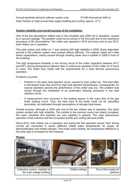
Photos<br />
Collectors system, installed <strong>at</strong><br />
the main college building<br />
Chilled ceilings<br />
One of the supply air<br />
systems<br />
page 33


