
You also want an ePaper? Increase the reach of your titles
YUMPU automatically turns print PDFs into web optimized ePapers that Google loves.
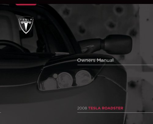
<strong>Owners</strong> <strong>Manual</strong><br />
2008 TESLA ROADSTER
A WORD TO ROADSTER OWNERS<br />
Thank you for choosing a Tesla Roadster. Not only have you chosen one of the finest sports cars on the road, you have also<br />
chosen the most energy efficient sports car ever sold. You are participating in a revolution, demonstrating that kicking the oil<br />
habit does not mean you have to give up performance and driving pleasure.<br />
Take the time to get well acquainted with your Tesla Roadster by reading this manual. The more you know and understand<br />
about your vehicle, the more safety and pleasure you’ll experience driving it.<br />
Tesla’s cars are unique, and Tesla Motors knows your Tesla Roadster best. So when service or maintenance is required, Tesla<br />
Motors is the place to go. Visit us regularly at www.teslamotors.com for more information about your Tesla Roadster. By signing<br />
into the owners area of this web site, you can access all the information you need about your specific vehicle, including service<br />
information.<br />
Enjoy your Tesla Roadster!<br />
Tesla Motors<br />
San Carlos, California, USA
Table of Contents<br />
Introduction and consumer information<br />
Important notes about your vehicle 1-2<br />
Important notes about this manual 1-3<br />
Consumer information 1-4<br />
Your vehicle at a glance<br />
Exterior 2-2<br />
Interior 2-4<br />
Seating and safety restraints<br />
Seats 3-2<br />
Seat belts 3-3<br />
Airbag system 3-6<br />
Doors, locks, and security<br />
Keys 4-2<br />
Doors 4-4<br />
Trunk 4-6<br />
Vehicle security 4-7<br />
Charging your vehicle<br />
General information about charging 5-2<br />
Charge settings 5-4<br />
Charging components 5-6<br />
Audio and navigation systems 8-1<br />
Maintenance and care<br />
Maintenance 9-2<br />
Fluid reservoirs 9-4<br />
Windshield wiper and washer 9-6<br />
Cleaning and vehicle care 9-7<br />
Roadside emergencies<br />
Tool kit 10-2<br />
Energy Depletion 10-3<br />
Tire repair 10-4<br />
Wheels 10-6<br />
Fuse replacement 10-7<br />
Bulb replacement 10-9<br />
Raising the vehicle 10-11<br />
Vehicle recovery 10-13<br />
Technical specifications<br />
Vehicle identification 11-2<br />
Wheels and tires 11-4<br />
Approved fluids and capacities 11-14<br />
Vehicle dimensions and weights 11-15<br />
Subsystem specifications 11-17<br />
Driving your vehicle<br />
Driving basics 6-2<br />
Switches and controls 6-7<br />
Instruments 6-11<br />
Comfort and convenience<br />
Power windows 7-2<br />
Rear view mirrors 7-3<br />
Interior temperature control 7-4<br />
Interior accessories 7-7<br />
Removable roof 7-9<br />
HomeLink® 7-15<br />
For information on how to use the Touch Screen, the High Power Connector, and the audio and<br />
navigation systems, refer to the separate manuals provided in your owners package.
Introduction & consumer information<br />
Important notes about your vehicle<br />
Electric vehicle precautions 1-2<br />
California Proposition 65 1-2<br />
Vehicle modifications 1-2<br />
Service data recording 1-2<br />
Change of address or ownership 1-2<br />
Important notes about this manual<br />
Read this manual first 1-3<br />
Copyright and trademarks 1-3<br />
Symbols glossary 1-3<br />
Consumer information<br />
Reporting safety defects 1-4<br />
1-1
Important notes about your vehicle<br />
Introduction Important notes andabout consumer your information<br />
vehicle<br />
Electric vehicle precautions<br />
WARNING: HIGH VOLTAGE. The Tesla<br />
Roadster TM has both AC and DC high<br />
voltage systems in addition to a normal 12V<br />
DC system. High voltage is very dangerous<br />
and can cause personal injury including<br />
electric shock, severe burns and even fatal<br />
injury. Always observe and obey the<br />
instructions on all labels attached to<br />
components on your vehicle - they are there<br />
for your safety. Do not touch, remove or<br />
replace any high voltage parts. If your vehicle<br />
is involved in an accident, do not touch any<br />
high voltage wiring (identified by the orange<br />
outer sleeving), the connectors or the<br />
components connected to the wiring.<br />
California Proposition 65<br />
WARNING: Certain vehicle components<br />
contain or emit chemicals known to the<br />
State of California to cause cancer and birth<br />
defects or other reproductive harm. In<br />
addition, certain fluids contained in vehicles<br />
and certain products of component wear<br />
contain or emit chemicals known to the State<br />
of California to cause cancer and birth<br />
defects or other reproductive harm.<br />
WARNING: Certain components of this<br />
vehicle such as airbag modules and<br />
seat belt pretensioners may contain<br />
Perchlorate Material. Special handling may be<br />
required for service or vehicle end of life<br />
disposal. See<br />
http://www.dtsc.ca.gov/hazardouswaste/per<br />
chlorate.<br />
Vehicle modifications<br />
WARNING: The fitting of non-approved<br />
parts and accessories, or the<br />
implementation of non-approved<br />
modifications to any vehicle components,<br />
including any “hacking” of the vehicle’s<br />
software, may be dangerous and could affect<br />
the safety of your vehicle and its occupants<br />
and also invalidate the terms and conditions<br />
of the New Vehicle Limited Warranty.<br />
WARNING: Tesla Motors TM will not<br />
accept any liability for death, personal<br />
injury or damage to property which may<br />
occur as a direct or indirect result of<br />
non-approved modifications or the fitment of<br />
non-approved accessories.<br />
If you have a disability which requires<br />
modification to your vehicle, consult Tesla<br />
Motors before making these modifications.<br />
Service data recording<br />
Service data recorders in your vehicle are<br />
capable of collecting and storing diagnostic<br />
information about your vehicle. This<br />
potentially includes information about the<br />
performance or status of various systems and<br />
control modules in your vehicle such as<br />
motor, accelerator, or brakes. To properly<br />
diagnose and service your vehicle, Tesla<br />
Motors and service facilities may access<br />
vehicle diagnostic information through a<br />
direct connection to your vehicle.<br />
Change of address or<br />
ownership<br />
If you change your address, it is in your best<br />
interest to notify Tesla Motors so we can<br />
contact you should the need arise. Send in<br />
the “Change of Address Notice” found in the<br />
New Vehicle Limited Warranty” booklet, or<br />
simply call Tesla Motors.<br />
If you sell your vehicle, leave all original<br />
owners package materials in the vehicle to<br />
make it available for the next owner.<br />
If you bought this vehicle used, either fill in<br />
the “Change of Address Notice” found in the<br />
New Vehicle Limited Warranty booklet, or<br />
simply call Tesla Motors.<br />
1-2 Introduction and consumer information
Important notes about this manual<br />
Important notes about this manual<br />
Read this manual first<br />
This owners manual contains a great deal of<br />
information you need to know about a Tesla<br />
Roadster. We urge you to read it carefully and<br />
familiarize yourself with the vehicle before<br />
driving.<br />
For your own safety, follow the instructions<br />
and warnings contained in this manual.<br />
Ignoring them could result in damage to the<br />
vehicle or personal injury to you or others.<br />
Vehicle damage caused by failure to follow<br />
instructions is not covered by the New<br />
Vehicle Limited Warranty.<br />
Keep this manual in your Roadster as a<br />
reference for the safe and enjoyable use of<br />
your Tesla Roadster. Should you sell your<br />
vehicle, be sure to provide this manual to the<br />
new owner.<br />
All specifications and descriptions are<br />
accurate at the time of printing. Because<br />
improvement is a constant goal at Tesla<br />
Motors, we reserve the right to make changes<br />
at any time, without notice and without<br />
obligation.<br />
This manual applies to all 2008 Tesla<br />
Roadsters. As a result, you may find some<br />
explanations for equipment or options not<br />
installed on your vehicle. When required,<br />
Tesla Motors distributes an addendum to<br />
provide updated information.<br />
An effective way to find the information you<br />
need is to use the index at the back of this<br />
manual. If you are unable to find the<br />
information you need, note that the following<br />
additional documents are included in your<br />
owners package and therefore the content<br />
may be elsewhere:<br />
• Audio and Navigation Guides - describes<br />
how to use the audio and navigation<br />
systems<br />
• Touch Screen Users <strong>Manual</strong> - describes<br />
how to use the screens to display<br />
important information while parking,<br />
driving, and charging the vehicle<br />
• Charging Your Vehicle - describes how to<br />
use the High Power Connector to charge<br />
your vehicle.<br />
• High Power Connector Installation<br />
<strong>Manual</strong> - provides planning guidelines for<br />
the installation of the High Power<br />
Connector as well as step-by-step<br />
installation instructions. This manual is<br />
included with the delivery of the High<br />
Power Connector.<br />
• Roadside Assistance Guide - describes<br />
the Tesla Motors Roadside Assistance<br />
program and provides instructions on<br />
how to transport the vehicle<br />
• Warranty Booklet - details the New<br />
Vehicle Limited Warranty<br />
• Tire Warranty - details the warranty for<br />
the vehicle’s tires<br />
In addition to these documents, Tesla Motors<br />
may include an addendum in your owners<br />
package if your vehicle specifications differ<br />
from those in this manual. If you are missing a<br />
document, contact Tesla Motors.<br />
Copyright and trademarks<br />
© 2008 TESLA MOTORS INC. All rights reserved.<br />
This material may not be reproduced<br />
or copied, in whole or in part, without the<br />
written permission of Tesla Motors, Inc.<br />
“Tesla MotorsTM” and “Tesla RoadsterTM” are<br />
trademarks of Tesla Motors, Inc. “HomeLink®”<br />
is a registered trademark of Johnson<br />
Controls, Inc. iPod® is a registered trademark<br />
of Apple Computer, Inc. Havoline® is a<br />
registered trademark of Chevron or its<br />
affiliates. TORX® is a registered trademark of<br />
Textron, Inc. All other trademarks are the<br />
property of their respective owners.<br />
Symbols glossary<br />
The following symbols used within this<br />
manual call your attention to specific types of<br />
information:<br />
WARNING: Indicates a situation in<br />
which serious bodily injury or death<br />
could result if the warning is ignored.<br />
Caution: Indicates a situation in which<br />
bodily injury or damage to your vehicle,<br />
or both, could result if the caution is ignored.<br />
Identifies items that must be disposed<br />
of safely to prevent unnecessary<br />
damage to the environment.<br />
Note: A note provides useful supporting<br />
information and sometimes suggests how to<br />
make better use of your vehicle.<br />
Introduction and consumer information<br />
1-3
Consumer information<br />
Consumer information<br />
Reporting safety defects<br />
If you believe that your vehicle has a defect<br />
which could cause a crash or could cause<br />
injury or death, you should immediately<br />
inform the National Highway Traffic Safety<br />
Administration (NHTSA) in addition to<br />
notifying Tesla Motors.<br />
If NHTSA receives similar complaints, it may<br />
open an investigation, and if it finds that a<br />
safety defect exists in a group of vehicles, it<br />
may order a recall and remedy campaign.<br />
However, NHTSA cannot become involved in<br />
individual complaints between you and<br />
another party such as Tesla Motors.<br />
To contact NHTSA, call the Auto Safety<br />
Hotline toll-free at 1-888-327-4236 (TTY:<br />
1-800-424-9153); go to<br />
http://www.safercar.gov; or write to:<br />
Administrator, NHTSA<br />
400 Seventh Street, SW<br />
Washington, DC 20590<br />
You can also obtain other information about<br />
motor vehicle safety from<br />
http://www.safercar.gov.<br />
1-4 Introduction and consumer information
Your vehicle at a glance<br />
Exterior<br />
Exterior overview 2-3<br />
Interior<br />
Dashboard overview 2-5<br />
2-1
Exterior<br />
1 2<br />
6<br />
5<br />
4<br />
3<br />
10<br />
9<br />
7<br />
8<br />
TR0109<br />
Your vehicle at a glance<br />
2-2 Your vehicle at a glance
Exterior<br />
Exterior overview<br />
1. Roof. See Removable roof, page 7-9.<br />
2. Charging port door. For details on vehicle charging, see the manual titled “Charging Your Vehicle” provided in your owners package.<br />
3. Wheels and tires. See Wheels and tires, page 11-4.<br />
4. Exterior door release. See Exterior door release, page 4-4.<br />
5. Emergency door unlock. See Emergency unlocking, page 4-5.<br />
6. Wheel bolts. See Removing the wheel, page 10-6.<br />
7. Trunk lock. See Opening the trunk, page 4-6.<br />
8. Vehicle recovery eye. See Attaching the vehicle recovery eye, page 10-14.<br />
9. Headlights. See Exterior lights, page 6-7.<br />
10. Exterior mirrors. See Exterior rear view mirrors, page 7-3.<br />
Your vehicle at a glance<br />
2-3
Interior<br />
Interior<br />
1 2 3 4<br />
i<br />
5<br />
6<br />
7<br />
TR0050<br />
17 16<br />
15 14 13 12<br />
11 10 9<br />
8<br />
2-4 Your vehicle at a glance
Interior<br />
Dashboard overview<br />
1. Touch Screen. See Touch Screen Users <strong>Manual</strong> provided in your owners package.<br />
2. Turn signals, headlight high beam and cruise control. See Exterior lights, page 6-7 and Cruise control, page 6-9.<br />
3. Instruments. See Instruments, page 6-11.<br />
4. Windshield wiper and washer. See Windshield wiper and washer, page 6-8.<br />
5. Hazard warning light switch. See Hazard warning, page 6-10.<br />
6. Heating and air conditioning. See Interior temperature control, page 7-4.<br />
7. Gear selector. See Selecting gears, page 6-3.<br />
8. Traction control switch. See Traction control, page 6-6.<br />
9. Accessory power socket. See Accessory power socket, page 7-7.<br />
10. Horn. See Horn, page 6-10.<br />
11. Starter switch. See Starting the vehicle, page 6-3.<br />
12. Hood release. See Opening and closing the hood, page 9-3.<br />
13. Trunk release. See Opening the trunk, page 4-6.<br />
14. Instrument panel illumination control. See Instrument panel lighting, page 6-14.<br />
15. Exterior lights master switch. See Exterior lights, page 6-7.<br />
16. Power windows. See Operating the windows, page 7-2.<br />
17. Central door locking. See Central door locking, page 4-4.<br />
Your vehicle at a glance<br />
2-5
Seating and safety restraints<br />
Seats<br />
Seat adjustment 3-2<br />
Seat belts<br />
General information 3-3<br />
Seat belt safety instructions 3-3<br />
Using the seat belts 3-3<br />
Seat belt reminder 3-4<br />
Wearing seat belts during pregnancy 3-4<br />
Seat belt tensioners 3-4<br />
Caring for seat belts 3-4<br />
Child seats and restraints 3-5<br />
Airbag system<br />
General information 3-6<br />
How the system works 3-6<br />
Deployment effects 3-6<br />
Obstruction of airbags 3-7<br />
Airbag warning indicator 3-7<br />
Airbag warning labels 3-7<br />
Using child seats 3-7<br />
Passenger airbag deactivation 3-7<br />
Airbag service information 3-8<br />
3-1
Seats<br />
TR0001<br />
Seat adjustment<br />
WARNING: Never adjust the driver’s<br />
seat while your vehicle is moving.<br />
Unexpected or sudden seat movement could<br />
result in an accident.<br />
Seating and Safety Restraints<br />
Driver’s seat position<br />
To adjust the forward/rearward position of<br />
the driver’s seat, raise the bar beneath the<br />
front of the seat and slide the seat to the<br />
required position. Release the bar to lock the<br />
1<br />
2<br />
seat into position. Ensure that the seat is<br />
locked in position before driving, by trying to<br />
slide the seat forward.<br />
To reduce the risk of injury in the event of an<br />
accident, Tesla recommends the following<br />
when adjusting seat position:<br />
• Adjust the seat so that you can press the<br />
foot pedals fully to the floor with your<br />
knees slightly bent.<br />
• Make sure that you can comfortably reach<br />
the top of the steering wheel.<br />
• Ensure a distance of at least 10 inches (25<br />
cm) between the steering wheel and your<br />
breastbone. The airbag will not provide<br />
adequate protection if you sit closer.<br />
• Fasten your seat belt correctly.<br />
Lumbar support<br />
Adjust lumbar support using the inflator bulb<br />
located on the outside front edge of the<br />
driver’s seat 1 or on the inside front edge of<br />
the passenger seat 2.<br />
To increase lumbar support, squeeze the bulb<br />
repeatedly until sufficient support is obtained.<br />
To reduce the amount of support, press the<br />
button located on the clamp between the<br />
hose and the inflator bulb.<br />
Head restraints<br />
Each seat is provided with a head restraint.<br />
The head restraints are integral with the seats<br />
and therefore can not be adjusted or<br />
removed.<br />
3-2 Seating and safety restraints
Seat belts<br />
Seat belts<br />
General information<br />
WARNING: Seat belts should be worn<br />
by all occupants, for every journey no<br />
matter how short. Failure to do so greatly<br />
increases the risk of death or serious injury in<br />
the event of an accident.<br />
It is an established fact that seat belts provide<br />
good protection in accidents. Therefore<br />
wearing a seat belt is required by law in most<br />
states.<br />
Both the driver and passenger seating<br />
positions are equipped with three-point<br />
inertia reel seat belts. Inertia reel belts are<br />
tensioned automatically and allow freedom<br />
of movement during normal driving<br />
conditions.<br />
The belt reel automatically locks, preventing<br />
movement of occupants, whenever your<br />
vehicle experiences the force associated with<br />
hard acceleration, braking, cornering or on<br />
impact in a collision. The reel may also lock<br />
when driving on steep hills or slopes.<br />
Seat belt safety instructions<br />
WARNING: Ensure that all seat belts are<br />
worn correctly. An improperly worn<br />
seat belt increases the risk of death or serious<br />
injury in the event of a collision.<br />
WARNING: Seat belts are designed to<br />
bear upon the bony structure of the<br />
body, and should be worn low across the<br />
pelvis, over the shoulder and across the<br />
chest. Avoid wearing the lap section of the<br />
belt across the abdominal area.<br />
WARNING: Always adjust the belt to<br />
remove slack. Seat belts worn too loose<br />
can result in injuries because they allow<br />
excessive forward movement in an<br />
accident.<br />
WARNING: Do not wear seat belts over<br />
hard, fragile or sharp items in clothing,<br />
such as pens, keys, eyeglasses, etc. In an<br />
impact, the pressure from the seat belt on<br />
such items can cause them to break, which in<br />
turn may cause serious injury.<br />
WARNING: Seat belts should not be<br />
worn with any part of the strap<br />
twisted.<br />
WARNING: Each belt assembly must be<br />
used by only one occupant. It is<br />
dangerous to put the belt around a child<br />
being carried on an occupant’s lap.<br />
WARNING: It is essential that seat belts<br />
that have been worn in an accident are<br />
replaced, even if damage to the assembly is<br />
not obvious. The belt anchors must also be<br />
checked.<br />
WARNING: Care must be taken to avoid<br />
contaminating the seat belt webbing,<br />
and seat belt mechanisms with any<br />
chemicals, liquids, grit, dirt or cleaning<br />
products. If a seat belt fails to retract or latch<br />
into the buckle, it must be replaced<br />
immediately.<br />
WARNING: No modifications or<br />
additions should be made that prevent<br />
the seat belt mechanism from taking up<br />
slack, or that prevent the seat belt being<br />
adjusted to remove slack. A slack belt greatly<br />
reduces the level of occupant protection.<br />
Using the seat belts<br />
TR0139<br />
Fastening the belt<br />
1. Ensure that the seat is correctly<br />
positioned.<br />
2. Take hold of the latch plate and pull it<br />
slowly across your chest and lap.<br />
3. Insert the latch plate into the buckle and<br />
press down until you hear a “click” that<br />
indicates it is securely locked into place.<br />
4. Pull the belt to check that it is securely<br />
fastened.<br />
5. Position the belt so that it is worn low<br />
across the front of the pelvis, and across<br />
the chest and shoulder.<br />
Seating and safety restraints<br />
3-3
Seat belts<br />
6. Pull the diagonal part of the belt towards<br />
the retractor to remove excess slack.<br />
Releasing the belt<br />
Release the seat belts by pressing the red<br />
button on the buckle. The belt retracts<br />
automatically.<br />
Seat belt reminder<br />
The seat belt warning indicator in the<br />
instrument panel illuminates<br />
whenever the driver’s seat belt is unbuckled.<br />
Also, an audible sound will be heard for six<br />
seconds if the starter switch is turned to the<br />
ON position and the drivers seat belt is<br />
unbuckled.<br />
Wearing seat belts during<br />
pregnancy<br />
WARNING: Pregnant woman should<br />
always wear seat belts to protect<br />
themselves and their unborn child.<br />
WARNING: Never place anything<br />
between you and the seat belt to<br />
cushion the impact in the event of an<br />
accident.<br />
The lap portion of the belt should be worn as<br />
low as possible across the hips, not the waist.<br />
Position the diagonal part of the belt<br />
between the breasts and to the side of the<br />
abdomen.<br />
If you have any concerns about wearing seat<br />
belts, contact your doctor.<br />
TR0140<br />
Seat belt tensioners<br />
WARNING: If the seat belt<br />
pre-tensioners have been activated<br />
once, they must be replaced. After any<br />
accident, always have the airbags, seat belt<br />
pre-tensioners and any associated<br />
components checked and, if necessary,<br />
replaced by Tesla Motors.<br />
The seat belts are equipped with<br />
pre-tensioners that activate in conjunction<br />
with the airbags and provide additional<br />
protection in the event of a severe frontal<br />
impact on your vehicle.<br />
The pre-tensioners automatically retract the<br />
seat belt buckle, reducing any slack in both<br />
the lap and diagonal portions of the belts,<br />
resulting in reduced forward movement of<br />
the occupant.<br />
Following an accident in which the<br />
pre-tensioners have been activated, the seat<br />
belts continue to function as restraints and<br />
must be worn if you drive your vehicle.<br />
Caring for seat belts<br />
WARNING: Regularly check the<br />
condition of both belts. Replace seat<br />
belts if you notice any damage to the belt<br />
webbing, fittings, retractor mechanisms or<br />
buckles.<br />
Three tests for checking seat belts:<br />
1. With the seat belt fastened, give the<br />
webbing nearest the buckle a quick pull.<br />
The buckle should remain securely<br />
locked.<br />
2. With the belt unfastened, unreel the<br />
webbing to its limit. Check that unreeling<br />
is free from snags and visually check the<br />
webbing for wear. Allow the webbing to<br />
retract, checking that retraction is<br />
smooth and complete.<br />
3. With the webbing half unreeled, hold the<br />
tongue plate and pull forward quickly.<br />
The mechanism must lock automatically<br />
and prevent further unreeling.<br />
If a seat belt fails any of these tests, contact<br />
Tesla Motors immediately.<br />
For seat belt cleaning information, see Seat<br />
belts, page 9-8.<br />
3-4 Seating and safety restraints
Seat belts<br />
Child seats and restraints<br />
Currently, child seats and restraints are not<br />
approved for use in your vehicle. Until these<br />
are available, Tesla Motors strongly<br />
recommends that children are not carried as<br />
passengers in your vehicle.<br />
WARNING: The seat belts fitted to your<br />
vehicle are designed to secure adult<br />
sized passengers only.<br />
WARNING: Children under age 12 and<br />
those weighing less than 80 lb (36 kg)<br />
are not of sufficient size to be carried safely<br />
wearing a standard seat belt of the type<br />
fitted to your vehicle.<br />
WARNING: It is dangerous for children<br />
to travel in any type of vehicle without<br />
being restrained by a harness, child seat, or<br />
restraint system suitable for both their age<br />
and size.<br />
WARNING: Never let a passenger hold a<br />
child on his or her lap while your vehicle<br />
is moving. The passenger cannot protect the<br />
child from injury in a collision.<br />
Seating and safety restraints<br />
3-5
Airbag system<br />
TR0082<br />
Airbag system<br />
General information<br />
The airbag for the driver is located in the<br />
padded hub of the steering wheel. The airbag<br />
for the passenger is located on the<br />
dashboard. These are indicated by the word<br />
AIRBAG on the trim.<br />
Provided the occupants are correctly seated<br />
and the seat belts are properly worn, the<br />
airbags provide additional protection to the<br />
chest and face of the occupants in the event<br />
of a severe frontal impact.<br />
Note: Airbags inflate and deflate very quickly<br />
and will not protect occupants against the<br />
effects of secondary impacts that may occur.<br />
1 2<br />
How the system works<br />
WARNING: The airbags are a<br />
supplemental restraint system<br />
providing additional protection in certain<br />
types of collisions only - they do not replace<br />
the need to wear a seat belt.<br />
Operation of the airbag system depends on<br />
the rate at which your vehicle's passenger<br />
compartment changes speed as a result of a<br />
collision.<br />
In the event of a collision, the airbag control<br />
unit monitors the rate of deceleration<br />
induced by the collision to determine<br />
whether the airbags should be deployed.<br />
When deployed, airbags inflate instantly, with<br />
considerable force accompanied by a loud<br />
noise. The inflated bag, together with the<br />
seat belt restraint system, limit the movement<br />
of the occupants, thereby reducing the risk of<br />
injury to the head and upper torso.<br />
The airbag system is not designed to operate<br />
as a result of:<br />
• Rear collisions<br />
• Minor front impacts<br />
• Minor side impacts<br />
• Heavy braking<br />
• Driving over bumps or potholes<br />
It follows, therefore, that significant superficial<br />
damage can occur without the air bags<br />
deploying or, conversely, that a relatively small<br />
amount of structural damage can cause the<br />
airbags to be deployed.<br />
Deployment effects<br />
WARNING: Following inflation, some<br />
airbag system components are hot. Do<br />
not touch until they have cooled.<br />
WARNING: The airbag module inflates<br />
with considerable speed and force. An<br />
inflating airbag can cause facial abrasions and<br />
other injuries. To limit these injuries, ensure<br />
that occupants are correctly seated, with the<br />
seat as far back as is practical, and are<br />
wearing seat belts.<br />
WARNING: The National Highway Traffic<br />
Safety Administration (NHTSA)<br />
recommends a minimum distance of 10 inches<br />
(25 cm) between an occupant’s chest and the<br />
driver’s airbag module.<br />
When the airbags are deployed, a fine powder<br />
is released. This is not a malfunction. However,<br />
the powder may irritate the skin and should be<br />
thoroughly flushed from the eyes and from<br />
any cuts or abrasions on the skin.<br />
3-6 Seating and safety restraints
Airbag system<br />
After inflation, the airbags will deflate to<br />
provide a gradual cushioning effect for the<br />
occupants and to ensure the driver's forward<br />
vision is not obscured.<br />
If the airbags have been deployed, always<br />
have the airbags, seat belt pre-tensioners and<br />
any associated components checked and, if<br />
necessary, replaced by Tesla Motors.<br />
After any accident, always have the airbags,<br />
seat belt pre-tensioners and any associated<br />
components checked and, if necessary,<br />
replaced by Tesla Motors.<br />
Obstruction of airbags<br />
WARNING: Do not allow passengers to<br />
obstruct the operation of the airbags<br />
by placing feet, knees or any other part of the<br />
body, or any other objects in contact with, or<br />
in close proximity to, an airbag module.<br />
WARNING: Do not attach or position<br />
items on an airbag cover which could<br />
interfere with the inflation of the airbag or be<br />
propelled inside your vehicle and injure<br />
occupants.<br />
Airbag warning indicator<br />
A warning indicator in the instrument<br />
panel alerts you of any malfunction of<br />
the airbag system.<br />
The components of the system being<br />
monitored include: the airbag modules, the<br />
seat belt pre-tensioners, the airbag control<br />
unit and the airbag wiring harness.<br />
When the starter switch is turned to the ON<br />
position, the airbag control unit monitors the<br />
readiness of the system’s electrical circuits.<br />
Contact Tesla Motors if:<br />
• The warning indicator fails to illuminate<br />
when the starter switch is turned to the<br />
ON position.<br />
• The warning indicator fails to extinguish<br />
within approximately six seconds after<br />
the starter switch is turned to the ON<br />
position.<br />
• The warning indicator illuminates while<br />
your vehicle is being driven.<br />
Airbag warning labels<br />
WARNING: Extreme hazard! Do not use<br />
a rearward facing child restraint on a<br />
seat protected by an airbag in front of it.<br />
Doing so increases the risk of death or<br />
serious injury when the airbag deploys.<br />
TR0138<br />
! WARNING<br />
Airbag warning information is printed on the<br />
driver’s and passenger’s sun visor.<br />
Using child seats<br />
DEATH or SERIOUS INJURY can occur<br />
Children 12 and under can be killed by the airbag<br />
NEVER put a rear facing child seat in the front<br />
Sit as far back as possible from the air bag<br />
ALWAYS use SEAT BELTS and CHILD RESTRAINTS<br />
WARNING: Currently, child seats and<br />
restraints are not approved for use in<br />
your vehicle. Until these are available, Tesla<br />
Motors strongly recommends that children<br />
are not carried as passengers in your vehicle,<br />
and that you do not fit any type of child seat<br />
into your vehicle. Death or serious injury may<br />
occur if the child is too close to the<br />
dashboard when the airbag inflates.<br />
Passenger airbag deactivation<br />
WARNING: Your vehicle is fitted with an<br />
airbag system that has no provision for<br />
switching off or deactivating the passenger<br />
airbag.<br />
Seating and safety restraints<br />
3-7
Airbag system<br />
Airbag service information<br />
WARNING: The disposal of used airbag<br />
units is subject to stringent regulations,<br />
and should only be handled by Tesla<br />
Motors.<br />
For your safety, a Tesla Motors technician,<br />
who is familiar with your vehicle, must<br />
perform the following tasks:<br />
• Removal, replacement, repair, or<br />
modification, of any wiring or component<br />
in the vicinity of airbag system<br />
components, including the steering<br />
wheel, steering column, dashboard and<br />
instrument panel.<br />
• Modification to the front or side of your<br />
vehicle, including the bumper and<br />
chassis.<br />
In addition, always seek the assistance of<br />
Tesla Motors if:<br />
• An airbag inflates<br />
• A pre-tensioner activates<br />
• The front or side of your vehicle is<br />
damaged, even if the airbag has not<br />
inflated<br />
• Any part of an airbag module cover<br />
shows signs of cracking or damage<br />
3-8 Seating and safety restraints
Doors, locks, and security<br />
Keys<br />
About your keys 4-2<br />
Using the key fob 4-2<br />
Doors<br />
Exterior door release 4-4<br />
Interior door release 4-4<br />
Central door locking 4-4<br />
Emergency unlocking 4-5<br />
Trunk<br />
Opening the trunk 4-6<br />
Closing the trunk 4-6<br />
Trunk interior release handle 4-6<br />
Vehicle security<br />
Alarm System 4-7<br />
Vehicle PIN code 4-8<br />
PIN lock 4-10<br />
Valet mode 4-11<br />
4-1
Keys<br />
TR0044<br />
1<br />
Doors, Keys Locks, and Security<br />
About your keys<br />
Caution: The key fob contains delicate<br />
electronic circuits and must be<br />
protected from impact, water damage<br />
and high temperatures. Avoid contact with<br />
solvents, waxes and abrasive cleaners.<br />
You have been supplied with three keys. Two<br />
of the keys are key fobs with three buttons:<br />
1. Lock button<br />
2. Unlock button<br />
3. Programmable button. See<br />
Programmable button, page 4-3.<br />
Keep one of the keys in a secure place for use<br />
in emergencies. If you lose a key, contact<br />
Tesla Motors for a replacement.<br />
3<br />
2<br />
TR0090<br />
Using the key fob<br />
The buttons on the key fob transmit a coded<br />
radio signal to a receiver in your vehicle. It is<br />
not necessary to point the key fob at your<br />
vehicle, but you must be within operating<br />
range and you must hold the button down for<br />
two seconds. The operating range will vary<br />
according to the key fob’s battery condition<br />
and other physical factors.<br />
If the vehicle can not be locked or unlocked<br />
using the associated button on the key fob, it<br />
may be necessary to change the battery in<br />
the key fob. See Replacing the key fob’s<br />
battery, page 4-3.<br />
Note: Interference from other radio<br />
equipment operating on a similar frequency<br />
may affect operation of the key fob. If this<br />
happens, operate the key fob as close to your<br />
vehicle as possible. If you are unable to<br />
unlock your vehicle with the key fob, use the<br />
emergency key lock. See Emergency<br />
unlocking, page 4-5.<br />
Locking<br />
WARNING: Never leave anyone in your<br />
vehicle when it is locked using the key<br />
fob. The interior door release handles will<br />
operate, but because the car was locked<br />
using the key fob, the alarm will sound. To<br />
re-open the doors using the exterior door<br />
release handles, you must first disarm the<br />
alarm using the key fob.<br />
Press the Lock button on the key fob to<br />
lock the doors and arm the alarm.<br />
The turn signals will flash once and the red<br />
alarm indicator on the console (illustrated on<br />
page 4-7) will illuminate and continue to flash<br />
on and off while the vehicle is locked. If you<br />
push the Lock button after the vehicle has<br />
already been locked, you’ll hear a<br />
confirmation beep.<br />
If a door, the hood or the trunk are not fully<br />
closed when the lock button is pressed, the<br />
turn signals will not flash and your vehicle is<br />
not armed. Check that the doors, hood and<br />
trunk are fully closed, then re-lock your<br />
vehicle.<br />
If any attempt is made to open the doors or<br />
the hood after the alarm has been set, the<br />
horn will sound and the turn signals will flash<br />
for one minute. See Alarm System, page 4-7.<br />
4-2 Doors, locks, and security
Keys<br />
Unlocking<br />
Press the Unlock button on the key fob<br />
to unlock the doors and disarm the<br />
alarm.<br />
The turn signals flash twice and the red alarm<br />
indicator on the console extinguishes.<br />
Note: If neither door or trunk are opened<br />
within one minute, the doors will<br />
automatically re-lock and the alarm will arm.<br />
Programmable button<br />
This button can be programmed to<br />
perform one of the following functions:<br />
• Alarm<br />
The horn sounds and the exterior lights<br />
flash for one minute. Press again to cancel<br />
the alarm.<br />
• Trunk release<br />
Opens the trunk.<br />
• Open or close a HomeLink® device<br />
Operates devices such as a garage door<br />
or gate.<br />
To program this button, use the Touch<br />
Screen. Refer to the Touch Screen Users<br />
<strong>Manual</strong>, provided in your owners package.<br />
To activate the programmed function, press<br />
and hold the button for two seconds.<br />
Replacing the key fob’s battery<br />
The key fob’s battery should last for<br />
approximately one year depending on use.<br />
When the battery needs replacing, you’ll<br />
TR0156<br />
notice a deterioration in performance. For<br />
example, you’ll gradually need to be closer to<br />
the vehicle to operate the key fob.<br />
To replace the battery:<br />
1. Remove the securing screw on the rear of<br />
the key fob and carefully separate the two<br />
halves. Avoid damaging the seal between<br />
the two halves.<br />
2. Remove the batteries, taking care to<br />
avoid touching the circuit board or the<br />
contact surfaces of the battery holder.<br />
3. Fit two new batteries (type CR1616) with<br />
the ‘+’ sides facing upwards.<br />
If possible, avoid touching the flat<br />
surfaces of the battery because finger<br />
marks will reduce battery life. Wipe the<br />
battery clean before fitting.<br />
4. Assemble the two halves of the key fob.<br />
Compliance<br />
The key fob complies with Title 47 CFR Part<br />
15 Subpart C rules for intentional radiators.<br />
Operation is subject to the following<br />
conditions:<br />
• This device may not cause harmful<br />
interference.<br />
• This device must accept any interference<br />
received, including interference that may<br />
cause undesired operation.<br />
Any changes or modifications to the key fob<br />
not expressly approved by the manufacturer<br />
or Tesla Motors could void the user’s<br />
authority to operate the equipment.<br />
Transmitter FCC ID: L2M001004<br />
Doors, locks, and security<br />
4-3
Doors<br />
TR0091 TR0092 TR0093<br />
Doors<br />
Exterior door release<br />
With the doors unlocked, press the touch pad<br />
(located in the air inlet on the door) to release<br />
the door. Pull the door to open.<br />
Note: The door release touch pads operate<br />
only if the doors are unlocked.<br />
Interior door release<br />
From inside your vehicle, pull the interior<br />
door release handle to unlock and open the<br />
door.<br />
Central door locking<br />
For your security, you can lock both doors<br />
from inside your vehicle by pressing the<br />
central locking switch on the driver’s door<br />
panel.<br />
Press the switch once to lock the doors and<br />
inhibit the use of the exterior door release<br />
touch pads. The alarm indicator on the center<br />
console will illuminate when the doors are<br />
locked (except if the vehicle is moving over 5<br />
mph).<br />
Press the switch to unlock the doors and<br />
enable operation of the exterior door release<br />
touch pads. You can also unlock the doors<br />
using the key fob.<br />
Note: The central door locking switch does<br />
not operate if the doors have been locked<br />
using the key fob. You’ll need to unlock the<br />
doors using the key fob. The central door<br />
locking switch also does not operate if a door,<br />
trunk, or the hood is not completely closed.<br />
4-4 Doors, locks, and security
Doors<br />
Drive away locking<br />
For your security, the doors lock and the<br />
trunk release switch is inhibited whenever<br />
your vehicle’s speed exceeds 5 mph.<br />
The trunk release button is reactivated when<br />
your vehicle’s speed is less than 5 mph.<br />
Emergency unlocking<br />
If the key fob fails to unlock the doors (for<br />
instance if there is an electrical failure), you<br />
can unlock the driver’s door using the<br />
mechanical key.<br />
A lock is located on the underside of the<br />
driver’s door. Turn the key clockwise to<br />
unlock the door.<br />
Note: If active, the alarm will sound when the<br />
door is opened. To cancel the alarm, press the<br />
unlock button on the key fob or enter the PIN<br />
Code on the Touch Screen. For details, refer<br />
to the Touch Screen Users <strong>Manual</strong> provided in<br />
your owners package.<br />
TR0146<br />
Doors, locks, and security<br />
4-5
2: 0PM<br />
6<br />
5<br />
4<br />
3<br />
2<br />
1<br />
0<br />
rpm<br />
7 8<br />
9<br />
10<br />
1<br />
12<br />
13<br />
14<br />
15 0<br />
60<br />
70 80 90<br />
50<br />
1 0<br />
40<br />
10<br />
30<br />
120<br />
20<br />
130<br />
10<br />
140<br />
mph<br />
FAULT<br />
BRAKE<br />
CRUISE<br />
x1 0 150<br />
P R N 1 2<br />
TC<br />
R 1<br />
2<br />
TC<br />
Trunk<br />
To close the trunk,<br />
use both hands<br />
to firmly but gently<br />
push down on one<br />
side of the rear<br />
spoiler until you<br />
hear it “click”<br />
into place. Repeat<br />
for the other side.<br />
2:00PM<br />
TR0108<br />
Trunk<br />
Opening the trunk<br />
To open the trunk, press the trunk release<br />
button on the dashboard, or insert the key in<br />
the external lock and turn counter-clockwise.<br />
You can also use the key fob if you have set<br />
up the its programmable button to remotely<br />
open the trunk. For details on programming<br />
the key fob, refer to the Touch Screen Users<br />
<strong>Manual</strong> provided in your owners package.<br />
The trunk release button is disabled when the<br />
doors are locked with the key fob, or when<br />
your vehicle’s speed exceeds 5 mph.<br />
Closing the trunk<br />
Close the trunk one side at a time. Use both<br />
hands to firmly but gently apply downward<br />
pressure on one side of the rear spoiler until<br />
you hear it click into place. Repeat for the<br />
other side.<br />
TR0149<br />
Trunk interior release handle<br />
Your vehicle is equipped with a mechanical<br />
trunk release handle that provides a means of<br />
escape in the event that a person becomes<br />
locked inside the trunk. Adults are advised to<br />
familiarize themselves with the operation and<br />
location of the release handle.<br />
A T-shaped handle is located at the back of<br />
the trunk towards the drivers side of the<br />
vehicle. This handle is made using a<br />
luminescent material that glows for hours<br />
after a brief exposure to ambient light. To<br />
open the trunk from the inside, pull the<br />
T-shaped handle and push up on the trunk lid.<br />
4-6 Doors, locks, and security
Vehicle security<br />
Vehicle security<br />
Alarm System<br />
Your vehicle is equipped with an anti-theft<br />
alarm system to prevent it from being stolen.<br />
The alarm is switched on automatically when<br />
you lock the doors with the key fob. The turn<br />
signals flash once to confirm that your vehicle<br />
is locked and the alarm indicator on the<br />
center console illuminates and flashes while<br />
the vehicle is locked. An audible tone will also<br />
be heard from inside your vehicle.<br />
Once activated, the alarm monitors the<br />
opening of the:<br />
• Hood<br />
• Doors<br />
If a door is opened without the key fob, the<br />
alarm sounds.<br />
To switch off the alarm, unlock the doors<br />
using the key fob or enter the PIN Code on<br />
the Touch Screen.<br />
Note: If the doors are unlocked with the key<br />
fob, they will automatically re-lock if neither<br />
the trunk or a door is opened within one<br />
minute of the unlock button being pressed.<br />
Alarm indicator<br />
An indicator on the center console will flash<br />
whenever the alarm system is active.<br />
TR0147<br />
Vehicle mislock<br />
If the system detects a mislock, the doors will<br />
not lock and the alarm will not be activated.<br />
Always check that the doors are locked<br />
before leaving your vehicle.<br />
The turn signals will not flash if you press the<br />
lock button on the key fob and a mislock has<br />
been detected. Check that both doors, the<br />
hood and the trunk are fully closed before<br />
pressing the lock button again. If the problem<br />
persists, contact Tesla Motors.<br />
Switching off the alarm<br />
If the alarm is triggered, the horn will sound<br />
for one minute and the turn signals will flash<br />
to attract attention. To silence the alarm,<br />
press the UNLOCK button on the key fob or<br />
enter your PIN code on the Touch Screen.<br />
Note: Turning the starter switch to the ACC<br />
position will silence the alarm. However, it will<br />
not be possible to start your vehicle until you<br />
either press the Unlock button on the key fob<br />
or enter the PIN code on the Touch Screen.<br />
For details on using the Touch Screen, see the<br />
Touch Screen Users <strong>Manual</strong> provided in your<br />
owners package.<br />
Doors, locks, and security<br />
4-7
Vehicle security<br />
Vehicle PIN code<br />
As an alternate level of vehicle security, you<br />
can restrict operation of your vehicle until a<br />
PIN code is entered. The PIN code is used by<br />
the following features that can be selected on<br />
the Touch Screen’s parked screen (shown<br />
above, the parked screen is active whenever<br />
the hand brake is engaged).<br />
Valet mode. See Valet mode,<br />
page 4-11.<br />
PIN Lock. See PIN lock,<br />
page 4-10.<br />
Tesla Motors requires that you set your PIN<br />
code when you receive your vehicle.<br />
Note: If at some point in the future you sell<br />
your vehicle, remember to inform the new<br />
owner of the PIN code.<br />
Setting the PIN code<br />
With the hand brake engaged, touch<br />
the SETTINGS icon on the main ‘parked<br />
screen to display the settings screen.<br />
Press the right arrow icon to navigate to the<br />
second settings screen.<br />
Touch Security PIN.<br />
If a PIN code has been previously set, you will<br />
be asked to enter the old PIN code. Enter the<br />
old PIN code by touching the numbers on the<br />
screen and then touch OK. If you enter an<br />
incorrect PIN code, an invalid entry message<br />
will be displayed. Either enter the correct PIN<br />
code or touch the EXIT icon to return to the<br />
previous screen.<br />
You will be then be asked to enter the new<br />
PIN code. Enter a new PIN code and then<br />
touch OK.<br />
Note: The PIN code must be between four<br />
and eight digits in length.<br />
You will then be asked to confirm the new PIN<br />
code. Enter the new PIN code again and then<br />
touch OK.<br />
If the PIN code does not match the previously<br />
entered code a message will be displayed<br />
telling you that the PINs differ and you will<br />
need to enter the PIN code again.<br />
4-8 Doors, locks, and security
Vehicle security<br />
If the PIN codes match, then the PIN Code Set<br />
screen will be displayed.<br />
Touch OK to return to the Settings screen.<br />
Note: Always keep a record of your PIN code<br />
and store it in a safe place. Do not store your<br />
PIN code in your vehicle.<br />
Doors, locks, and security<br />
4-9
Vehicle security<br />
PIN lock<br />
When activated, the PIN lock inhibits starting<br />
and driving your vehicle until the PIN code is<br />
entered on the Touch Screen.<br />
Activating PIN lock<br />
To activate the PIN lock, touch the<br />
LOCK icon on the main parked screen.<br />
Enter your PIN code. The Touch Screen<br />
displays a message (shown above) telling you<br />
that the PIN lock is activated.<br />
If a PIN code has not been set, the Touch<br />
Screen displays a message telling you to<br />
enter a new PIN code. Touch OK to enter a<br />
new PIN code. See Vehicle PIN code,<br />
page 4-8.<br />
Deactivating PIN lock<br />
To deactivate the PIN lock, touch the<br />
UNLOCK icon to display the PIN code<br />
entry screen.<br />
Enter your PIN code and then touch OK. If the<br />
correct PIN code was entered, the Touch<br />
Screen displays the main parked screen.<br />
If you enter an incorrect PIN code, a message<br />
is displayed telling you that you’ve made an<br />
invalid entry. Either enter the correct PIN<br />
code or touch the EXIT icon to return to the<br />
previous screen.<br />
4-10 Doors, locks, and security
Vehicle security<br />
Valet mode<br />
For your peace of mind, your vehicle has a<br />
unique valet mode for those times that your<br />
vehicle is parked by another person.<br />
When valet mode is active, your vehicle’s<br />
power is limited and the Touch Screen<br />
displays activity information about the<br />
vehicle. Operation of the Touch Screen is<br />
restricted to the valet mode screen which<br />
displays information on how your vehicle was<br />
used while in valet mode.<br />
Valet mode can only be deactivated by<br />
entering the vehicle’s PIN code.<br />
Activating Valet mode<br />
To activate valet mode, touch the bow<br />
tie icon on the Touch Screen’s main<br />
parked screen.<br />
Provided a vehicle PIN code has been set,<br />
you’ll be prompted to enter your PIN code.<br />
Enter your PIN code and touch OK. The Touch<br />
Screen displays the Valet Mode Activated<br />
screen.<br />
If a PIN code has not been set, the Touch<br />
Screen displays a message telling you to<br />
enter a new PIN code. Touch OK to enter a<br />
new PIN code. See Vehicle PIN code,<br />
page 4-8.<br />
The Touch Screen displays the following<br />
information for the current period that valet<br />
mode has been active:<br />
• Distance travelled<br />
• Top speed reached<br />
• Unlock attempts (the number of<br />
unsuccessful attempts at entering a PIN<br />
code)<br />
• Trunk openings (the number of times the<br />
trunk has been opened)<br />
Deactivating Valet mode<br />
To deactivate valet mode, touch the<br />
UNLOCK icon to display the PIN code<br />
entry screen.<br />
Enter your PIN code and then touch OK. If the<br />
correct PIN code was entered, the Touch<br />
Screen displays the main parked screen.<br />
If you enter an incorrect PIN code, a message<br />
is displayed telling you that you’ve made an<br />
invalid entry. Either enter the correct PIN<br />
code or touch the EXIT icon to return to the<br />
previous screen.<br />
Doors, locks, and security<br />
4-11
Charging your vehicle<br />
General information about charging<br />
The Battery 5-2<br />
Designed to be plugged in 5-2<br />
Leaving the vehicle unplugged 5-2<br />
Storing your vehicle 5-3<br />
Charge level & mileage are estimates 5-3<br />
How long does it take to charge? 5-3<br />
Charge settings<br />
About charge settings 5-4<br />
Four types of charge 5-4<br />
Schedule the charge time 5-4<br />
Setting current limit 5-4<br />
Cost 5-5<br />
Charging components<br />
Main charging components 5-6<br />
5-1
General information about charging<br />
Charging General information your vehicle about charging<br />
Important!<br />
Caution: If the Battery’s charge level<br />
falls to 0%, it must be plugged in<br />
immediately. Failure to do so can<br />
permanently damage the Battery and this<br />
damage is not covered by the New Vehicle<br />
Limited Warranty. Also, if you allow the<br />
Battery to fall to a critically low level it may<br />
not be possible to charge the vehicle. If you<br />
are unable to charge the vehicle, contact<br />
Tesla Motors.<br />
WARNING: The Battery has no parts<br />
that an owner, or a non-Tesla authorized<br />
technician can service. Under no<br />
circumstances should you open or tamper<br />
with the Battery. Always contact Tesla Motors<br />
to arrange for Battery servicing.<br />
At the end of its service life, the Battery<br />
will be recycled. Contact Tesla Motors<br />
for recycling arrangements.<br />
The Battery<br />
The Tesla Roadster’s Battery provides power<br />
to the motor as well as all the other electrical<br />
systems on the vehicle, such as lights,<br />
instruments, audio system, etc.<br />
The Battery is one of the largest and most<br />
advanced battery packs in the world,<br />
consisting of several thousand lithium-ion<br />
battery cells that store enough energy for the<br />
vehicle to travel over 200 miles without<br />
recharging.<br />
Note: Actual range will vary based on driving<br />
style. The vehicle consumes more energy if<br />
you are driving aggressively, driving up hills,<br />
or are using more resources such as air<br />
conditioning. Also, over time, the Battery<br />
experiences a gradual loss of capacity,<br />
inherent in all lithium-ion batteries. So, as<br />
your vehicle ages, the capacity of the Battery<br />
declines.<br />
As you drive your vehicle, the level of charge<br />
in the Battery is depleted and you’ll need to<br />
recharge it. The Roadster’s built-in charging<br />
system allows you to easily recharge it by<br />
connecting an electrical power supply to the<br />
vehicle’s charging port.<br />
Designed to be plugged in<br />
The Tesla Roadster is designed to be plugged<br />
in when not in use. This ensures that the next<br />
time you use the vehicle, it is fully charged<br />
and ready to go. There is no advantage to<br />
waiting until battery level is low before<br />
charging. In fact, by plugging it in every night,<br />
you eliminate the risk of damage that could<br />
be caused by over-discharging the battery.<br />
When plugged in, the vehicle takes care of<br />
itself, preserving battery life by managing the<br />
charge level and keeping the Battery at an<br />
ideal temperature. The vehicle wakes up<br />
every 24 hours and, if needed, automatically<br />
initiates the charging process to keep the<br />
Battery at an optimum charge level.<br />
If you’re not driving your vehicle every day,<br />
see Storing your vehicle, page 5-3.<br />
Leaving the vehicle unplugged<br />
Even when you’re not driving the vehicle, the<br />
Battery will slowly lose its charge. Therefore,<br />
when you’re not using the vehicle, you should<br />
leave it plugged in. However, situations may<br />
arise in which you must leave the vehicle<br />
unplugged for an extended time (for<br />
example, at an airport when travelling for a<br />
couple of weeks). If this is the case, it is your<br />
responsibility to ensure that the Battery does<br />
not become fully depleted. Charge the<br />
Battery to a maximum level before leaving it,<br />
and keep in mind that when the vehicle is left<br />
unplugged, the Battery’s charge level will<br />
drop to a level of approximately 50% within<br />
the first week, and then decline at a rate of<br />
approximately 5% each subsequent week.<br />
Plan accordingly to ensure that the Battery<br />
never approaches a level of 0%.<br />
Over-discharge can permanently damage the<br />
Battery.<br />
If for some reason, you are unable to keep the<br />
vehicle plugged in when it is not being used,<br />
it is up to you to preserve battery life by<br />
paying attention to the charge level and the<br />
temperature (see bulleted list below). If<br />
leaving your vehicle unplugged for more than<br />
24 hours, follow these do’s and don’ts to<br />
avoid prematurely decreasing the life of your<br />
vehicle’s Battery:<br />
• DO leave the vehicle plugged in whenever<br />
possible.<br />
• DO maintain at least a 15% charge level in<br />
the Battery if leaving it unplugged for<br />
more than 48 hours.<br />
5-2 Charging your vehicle
General information about charging<br />
• DO charge the Battery to a full charge<br />
before leaving it unplugged. This<br />
maintains the charge level needed to<br />
keep the Battery’s electronics<br />
operational. If storing for more than 15<br />
days, it is strongly recommended that you<br />
keep it plugged in.<br />
• DO NOT expose an unplugged vehicle to<br />
ambient temperatures below -20°F or<br />
above 120°F.<br />
Use the vehicle’s Touch Screen to determine<br />
the charge level and temperature of the<br />
Battery. For details, refer to the Touch Screen<br />
Users <strong>Manual</strong>, provided in your owners<br />
package.<br />
Storing your vehicle<br />
If you plan to leave the vehicle unused for<br />
longer than 15 days, it is recommended that<br />
you leave the vehicle connected to the High<br />
Power Connector and select the ‘Storage’<br />
charge setting using the Touch Screen. When<br />
you charge the vehicle using the Storage<br />
charge setting, the vehicle is automatically<br />
kept at a reduced charge level to optimize the<br />
life of the individual cells within the Battery.<br />
Keep in mind that the reduced charge level<br />
also reduces the vehicle’s available driving<br />
range. So remember to change the setting<br />
back to ‘Standard’ before taking the vehicle<br />
on an extended drive. For details on how to<br />
select the Storage charge setting, refer to the<br />
Touch Screen Users <strong>Manual</strong>, provided in your<br />
owners package.<br />
Charge level & mileage are<br />
estimates<br />
The maximum level of charge the Battery will<br />
be charged to depends on the charge setting<br />
you select (see About charge settings,<br />
page 5-4). The Standard charge setting is the<br />
preferred setting for normal use. Selecting<br />
the Range or Performance charge settings<br />
will charge the Battery to its maximum<br />
allowable charge level, whereas selecting the<br />
Storage charge setting will charge the<br />
Battery to a relatively low level.<br />
The vehicle’s Touch Screen displays the<br />
charge level and number of miles you can<br />
drive on the remaining charge. The numbers<br />
that are displayed are estimates only. The<br />
Touch Screen allows you to display these<br />
estimates based on how you’ve been driving<br />
for the last mile (INST RANGE) or the last 32<br />
miles (RANGE). Therefore, if you’ve driven on<br />
a flat highway for the past 32 miles, and you<br />
have now been driving up a steep slope for<br />
the last mile, the number of miles you can<br />
drive on the remaining charge will actually be<br />
less than the estimate that is displayed when<br />
RANGE is selected but is more accurate when<br />
INST RANGE is selected. Charge level and<br />
estimated remaining mileage are also<br />
displayed on the vehicle’s LCD panel (see<br />
page 6-11).<br />
The charge level and estimated mileage are<br />
continuously updated. Also, they may be<br />
lower or higher after a period of rest. For<br />
example, when parking your vehicle you<br />
notice that the estimated remaining mileage<br />
is 85. When returning to your vehicle a few<br />
hours later, you notice that the estimated<br />
mileage is now 91. This is normal behavior and<br />
is not a cause for concern. The mileage that is<br />
displayed when the vehicle has been at rest is<br />
more accurate.<br />
How long does it take to charge?<br />
The amount of time it takes to fully charge<br />
the vehicle will vary depending on the<br />
amount of current and voltage provided by<br />
the charging system. Charge time is also<br />
impacted by both the ambient temperature<br />
and the vehicle’s Battery temperature—if out<br />
of the optimal range, the HVAC system starts<br />
up and diverts a portion of the energy. It also<br />
depends on the charge setting you are using.<br />
For example, a full charge at Range or<br />
Performance takes approximately 15% longer.<br />
Use the following table as a guideline when<br />
estimating how long it will take to charge<br />
your vehicle. This table assumes you are<br />
charging a fully depleted Battery to a full<br />
charge using the Standard charge setting.<br />
Charge times are estimates only.<br />
Charge<br />
Current<br />
Charge Time<br />
(at 120 Volts)<br />
Charge Time<br />
(at 240 Volts)<br />
70 amps n/a 4 hours<br />
60 amps n/a 5 hours<br />
48 amps n/a 6 hours<br />
40 amps n/a 7 hours<br />
32 amps n/a 10 hours<br />
24 amps n/a 15 hours<br />
16 amps n/a 18 hours<br />
12 amps 40 hours 20 hours<br />
Charging your vehicle<br />
5-3
Charge settings<br />
Note: The charge process slows down as the<br />
Battery approaches a full charge. Therefore,<br />
reaching a high level of charge is much<br />
quicker than reaching a full charge.<br />
Charge settings<br />
About charge settings<br />
Your vehicle has been set up with default<br />
charging settings. However, you can override<br />
these default settings. You may want to<br />
optimize the charging environment when<br />
storing your vehicle, or you may want to<br />
extend the vehicle’s driving range. You can<br />
also reduce the default charge current, set a<br />
time that you want charging to begin, and<br />
display your electrical cost per charge.<br />
Charge settings can be changed using the<br />
Touch Screen. The various charge settings<br />
are summarized below. For details on how to<br />
use the Touch Screen to adjust settings, refer<br />
to the Touch Screen Users <strong>Manual</strong>, provided<br />
in your owners package.<br />
Four types of charge<br />
The charge setting always defaults to<br />
Standard charge. In other words, changing<br />
the charge type is a one-time event—the<br />
charge type reverts back to Standard the<br />
next time the charging port door is opened<br />
after the vehicle has been driven over a tenth<br />
of a mile.<br />
Storage<br />
If you are not using the vehicle for an<br />
extended period of time, Tesla recommends<br />
leaving the vehicle plugged in and setting the<br />
charge type to Storage.<br />
This setting charges the Battery to a medium<br />
level of charge to ensure the maximum<br />
lifetime of the cells within the Battery, while<br />
also maintaining the integrity of the vehicle’s<br />
electronic systems, such as the security<br />
system.<br />
This charge setting is automatically cancelled<br />
and reverts back to Standard if the vehicle’s<br />
charging port door is opened after the<br />
vehicle has been driven over a tenth of a mile.<br />
If the vehicle is driven after being charged<br />
using the Storage setting, the range of the<br />
vehicle will be limited because the charge<br />
level is lower than the other charge types.<br />
This is temporary and returns to normal after<br />
charging the vehicle using the Standard<br />
setting.<br />
Standard<br />
By default, the vehicle is set up to charge<br />
using the Standard charge setting—this<br />
setting provides the best performance while<br />
also maximizing the life of the Battery.<br />
Range<br />
This setting charges the Battery to the<br />
maximum available level. It also limits the<br />
vehicle’s power by 50%. The result is that the<br />
vehicle can achieve the maximum number of<br />
miles possible on a single charge.<br />
To preserve the life of the Battery, this charge<br />
setting is automatically cancelled and reverts<br />
back to Standard after 72 hours or if the<br />
vehicle’s charging port door is opened after<br />
the vehicle has been driven over a tenth of a<br />
mile.<br />
Caution: Repeated use of the Range<br />
charge setting reduces the lifetime of<br />
the cells within the Battery.<br />
Performance<br />
This setting is available for those rare times in<br />
which you want to achieve maximum power<br />
and hence, minimize the time it takes to<br />
accelerate from 0-60 mph. Use this setting<br />
with caution because it allows the Battery to<br />
run at a higher temperature—which reduces<br />
the life of the cells within the Battery.<br />
Frequent use of this setting is strongly<br />
discouraged.<br />
This setting also charges the cells within the<br />
Battery to the maximum available level.<br />
To preserve the life of the Battery, this charge<br />
setting is automatically cancelled and reverts<br />
back to Standard after 72 hours or if the<br />
vehicle’s charging port door is opened after<br />
the vehicle has been driven over a tenth of a<br />
mile.<br />
Caution: Repeated use of the<br />
Performance setting reduces the<br />
lifetime of the cells within the Battery.<br />
5-4 Charging your vehicle
Charge settings<br />
Schedule the charge time<br />
If you don’t want the vehicle to begin<br />
charging immediately after you plug it in, you<br />
can set a charge start time. This is a useful<br />
way to charge the vehicle during non-peak<br />
hours when there is less demand on your<br />
electrical system and your electricity may<br />
cost less.<br />
For details on setting charge costs, refer to<br />
the Touch Screen Reference Guide provided<br />
in your owners package.<br />
Setting current limit<br />
The current limit is automatically set to the<br />
maximum possible value available from the<br />
attached power supply. With the charging<br />
port door open, you can manually reduce the<br />
current by selecting an alternate value. If you<br />
do so, the reduced limit remains in effect until<br />
you manually increase it. When you manually<br />
change the current limit, the change is<br />
applied only to your physical location and it<br />
stays in effect for that location until you<br />
manually change it. The vehicle location is<br />
determined by the internal global positioning<br />
system (GPS). This allows you to set a<br />
different current limit for each of your<br />
charging locations.<br />
Cost<br />
You can display the cost of a charge on the<br />
Touch Screen when the vehicle has finished<br />
charging. You can obtain an accurate reading<br />
of your power cost for each charge cycle by<br />
entering the cost of power (in kWH) on the<br />
Cost Settings screen. In most areas, you can<br />
obtain your power costs from your utility bill.<br />
Charging your vehicle<br />
5-5
4<br />
3<br />
2<br />
1<br />
0<br />
6<br />
7 8<br />
5<br />
rpm<br />
9<br />
10<br />
1<br />
12<br />
13<br />
14<br />
15<br />
BRAKE<br />
CRUISE<br />
60<br />
70 80 90<br />
50<br />
1 0<br />
40<br />
10<br />
30<br />
120<br />
20<br />
130<br />
10<br />
140<br />
0<br />
mph<br />
P R N 1 2<br />
FAULT<br />
TC<br />
Charging components<br />
7<br />
6<br />
5<br />
Main charging components<br />
1. Battery<br />
2. Charging port<br />
3. Charging port door<br />
4. Charging cable<br />
5. Cable hanger<br />
6. High Power Connector<br />
7. Smoke detector<br />
The High Power Connector is the primary<br />
source for recharging your vehicle.<br />
3<br />
1<br />
During normal use, the High Power Connector<br />
should be left on, even when the charging<br />
cable is not connected to the vehicle. The<br />
READY light on the control panel illuminates<br />
green to indicate that the High Power<br />
Connector is operating correctly.<br />
x1 0 150<br />
Although the High Power Connector is on and<br />
ready, no electricity is supplied until the<br />
charging cable is connected to the vehicle,<br />
and both the vehicle and the High Power<br />
Connector determine that it is safe for<br />
charging to begin.<br />
For details on how to use the High Power<br />
Connector to charge your vehicle, refer to the<br />
manual titled “Charging Your Vehicle,”<br />
provided in your owners package.<br />
4<br />
2<br />
TR0034<br />
Charging components<br />
5-6 Charging your vehicle
Driving your vehicle<br />
Driving basics<br />
Key positions 6-2<br />
Steering column lock 6-2<br />
Starting the vehicle 6-3<br />
Selecting gears 6-3<br />
Driving tips 6-3<br />
Hand brake 6-5<br />
Braking 6-5<br />
Anti-lock Braking System (ABS) 6-5<br />
Traction control 6-6<br />
Switches and controls<br />
Exterior lights 6-7<br />
Turn signals 6-8<br />
Windshield wiper and washer 6-8<br />
Cruise control 6-9<br />
Hazard warning 6-10<br />
Horn 6-10<br />
Instruments<br />
LCD panel 6-11<br />
Warning indicators 6-12<br />
Gear position indicators 6-13<br />
Instrument panel lighting 6-14<br />
6-1
Driving basics<br />
OFF<br />
ACC<br />
ON<br />
START<br />
ACC<br />
• Park mode still active<br />
• Audio and navigation systems<br />
operational<br />
ON<br />
• All instruments, warning indicators and<br />
electrical circuits operational<br />
To release the steering column lock, insert the<br />
key into the starter switch and turn to the<br />
ACC position. If it is difficult to turn the key, a<br />
small movement of the steering wheel will<br />
help to disengage the steering lock.<br />
TR0004<br />
Driving your basics vehicle<br />
Key positions<br />
The starter switch is located on the<br />
right-hand side of the steering column and<br />
uses the following key positions to control<br />
the electrical circuits and steering column<br />
lock.<br />
OFF<br />
• Park mode active<br />
• Interior and trunk lights operational<br />
• Exterior and hazard warning lights<br />
operational<br />
• Central door locking master switch<br />
operational<br />
• Trunk release switch operational<br />
Note: When turning the key to the OFF<br />
position, the circuits that operate in ACC<br />
continue to operate until the key is removed.<br />
START<br />
• The vehicle initiates the start-up<br />
sequence to prepare for driving (if the<br />
brake pedal is pressed). The gear position<br />
indicator illuminates green and park<br />
mode is deactivated.<br />
Removing the key<br />
To remove the key, turn the key to the OFF<br />
position. Exterior lights (except hazard<br />
warning lights) automatically turn off when<br />
the key is removed from the starter switch.<br />
If the key has been left in the starter switch,<br />
an audible alert sounds when the driver’s<br />
door is opened.<br />
WARNING: Never remove the key from<br />
the starter switch while the vehicle is<br />
moving. The steering column lock will<br />
engage, making it impossible to steer the<br />
vehicle.<br />
Steering column lock<br />
The steering column lock is activated when<br />
the key is removed from the starter switch,<br />
but may not engage until the steering wheel<br />
is turned and the mechanism aligned.<br />
6-2 Driving your vehicle
Driving basics<br />
TR0304<br />
Starting the vehicle<br />
1:03AM<br />
PIN While Code starting, Chang foot<br />
braked<br />
brake must be pressed<br />
<br />
ID:881 Data:0x00000002<br />
EST.<br />
Follow these steps to prepare the vehicle for<br />
driving:<br />
1. Tesla recommends selecting the N gear<br />
position.<br />
2. Press and hold down the brake pedal.<br />
3. Insert the key into the starter switch, turn<br />
it to the START position, and release.<br />
When released, the key automatically<br />
returns to the ON position and, if the<br />
start-up sequence is successful, the N<br />
indicator will illuminate green and you’ll<br />
hear an audible tone. .<br />
Note: If the brake pedal is not pressed, a<br />
message is displayed on the Touch<br />
Screen. Press the brake pedal and turn<br />
the key to the START position again.<br />
The vehicle is now ready to be driven.<br />
Selecting gears<br />
The transmission has two selectable drive<br />
positions - forward (D) and reverse (R). In the<br />
neutral (N) position the gear selector rests<br />
between gears D and R.<br />
TR0008<br />
Indicator lights in the instrument panel<br />
illuminate to show the currently engaged<br />
gear.<br />
The vehicle can be driven away from<br />
stationary with the gear selector in position D<br />
or R.<br />
• R (Reverse). Selectable whenever the<br />
vehicle’s forward speed is less than 5<br />
mph. The maximum speed in reverse is<br />
limited to 15 mph. An audible tone will be<br />
heard when reverse gear is selected.<br />
• N (Neutral). Select this position and apply<br />
the hand brake if the vehicle needs to be<br />
stationary for a period of time.<br />
• D (Drive). Can be selected whenever the<br />
vehicle is stationary.<br />
Note: P (Park) is not a gear you can select. It<br />
is a state the vehicle is in when the<br />
transmission is locked and the rear wheels<br />
cannot turn. When the key is turned to the<br />
ACC position, this state is activated<br />
automatically, regardless of the position of<br />
the gear selector. In the event that the<br />
vehicle needs to hauled on a flatbed truck, P<br />
must be deactivated before the vehicle can<br />
be pulled onto the truck. See Vehicle<br />
recovery, page 10-13.<br />
Driving tips<br />
Driving an electric vehicle is similar to driving<br />
a gasoline-powered vehicle. Here are a few<br />
guidelines you should be aware of to help you<br />
maximize range.<br />
Drive sensibly to maximize range<br />
Energy consumption depends on driving<br />
habits and operating condition. Your vehicle<br />
is designed to travel over 200 miles on a<br />
charge.<br />
To get the maximum mileage from a charge,<br />
you should:<br />
• Avoid frequent acceleration and<br />
deceleration.<br />
• Anticipate stops and instead of using the<br />
brake pedal to slow down, move your foot<br />
off the accelerator. Whenever the vehicle<br />
is moving and your foot is off the<br />
accelerator, regenerative braking slows<br />
the vehicle and feeds energy back to the<br />
battery.<br />
Driving your vehicle<br />
6-3
Driving basics<br />
• Drive with the top on and the windows up<br />
to minimize aerodynamic drag.<br />
• Keep tires at the recommended inflation<br />
pressures.<br />
• Remove unnecessary belongings from<br />
the trunk.<br />
• Minimize the use of resources such as<br />
heating and air conditioning. Using seat<br />
heaters to keep warm is more efficient<br />
than heating the cabin.<br />
In addition to driving habits, energy<br />
consumption is also increased based on<br />
environmental conditions, such as cold<br />
weather and hilly roads.<br />
The Touch Screen’s Energy screen displays<br />
precise real-time feedback on the amount of<br />
energy you’re using. Energy feedback is also<br />
displayed on the LCD display on the<br />
instrument panel.<br />
Deep water<br />
Do not drive through flooded areas, water of<br />
unknown depth, or deep puddles. When<br />
driving through even a relatively shallow<br />
puddle, drive slowly to prevent water from<br />
entering the vehicle.<br />
Carrying items in cabin area<br />
The trunk is the preferred place to carry<br />
objects. In an accident, during hard braking,<br />
or sudden maneuvers, loose items carried in<br />
the vehicle’s cabin area can be thrown<br />
around, and cause injury to occupants unless<br />
securely fastened.<br />
6-4 Driving your vehicle
Driving basics<br />
Hand brake<br />
WARNING: Do not apply the hand<br />
brake when the vehicle is moving. This<br />
could result in a loss of control and may<br />
damage the rear brakes.<br />
The hand brake operates on the rear wheels<br />
only, and is totally independent of the foot<br />
operated hydraulic brake system.<br />
To apply the hand brake, pull the lever fully<br />
upwards.<br />
If the starter switch is in the ON<br />
BRAKE position and the hand brake is<br />
applied, the warning indicator in the<br />
instrument panel illuminates and the Touch<br />
Screen will display the main Parked screen.<br />
Caution: If the hand brake is applied<br />
when the brakes are hot (such as after<br />
prolonged or frequent hard use), care should<br />
be taken that the hand brake is securely<br />
engaged. As the brake discs cool, the amount<br />
of brake force applied by the lever will<br />
reduce.<br />
TR0005<br />
To release the hand brake, pull the lever up<br />
slightly, depress the button (shown in<br />
illustration) and fully lower the lever. The<br />
warning indicator will extinguish and the<br />
Touch Screen will display a Drive screen.<br />
Braking<br />
WARNING: After driving through heavy<br />
rain, some loss of braking response may<br />
be experienced. As soon as safety permits,<br />
apply the brakes to generate heat and dry the<br />
brake components. Never drive the vehicle<br />
through deep water - doing so can cause<br />
damage and void the New Vehicle Limited<br />
Warranty.<br />
The brakes operate through dual circuits. If<br />
one circuit fails, the other continues to<br />
function, but braking performance is<br />
reduced. If greater pedal effort, or longer<br />
stopping distances are experienced, the car<br />
should not be driven and Tesla Motors should<br />
be contacted as soon as possible.<br />
The brakes are servo-assisted, but only when<br />
the starter switch is in the ON position and<br />
the electrical systems are operating. Without<br />
servo assistance, greater pedal effort is<br />
required to control the vehicle, resulting in<br />
longer stopping distances.<br />
Regenerative braking<br />
Whenever the vehicle is moving and your<br />
foot is off the accelerator, regenerative<br />
braking slows the vehicle and feeds energy<br />
back to the battery. By anticipating your<br />
stops and simply removing your foot from<br />
the accelerator to slow down, you can take<br />
advantage of the energy gains of<br />
regenerative braking. A visual display on the<br />
instrument panel provides real-time<br />
feedback of the vehicle’s regenerative<br />
braking. See LCD panel, page 6-11.<br />
Anti-lock Braking System<br />
(ABS)<br />
WARNING: ABS cannot overcome the<br />
physical limitations such as stopping<br />
the vehicle in too short a distance, turning the<br />
vehicle at high speeds, or the lack of grip on<br />
the road’s surface.<br />
WARNING: Do not take risks when<br />
driving in the hope that ABS will correct<br />
errors of judgement. In all cases it is the<br />
driver's responsibility to drive with due care<br />
and attention.<br />
Your vehicle is equipped with an anti-lock<br />
braking system (ABS) that prevents the<br />
wheels from locking when maximum brake<br />
Driving your vehicle<br />
6-5
Driving basics<br />
pressure is applied. This allows you to<br />
maintain steering control during heavy<br />
braking on most road conditions.<br />
During emergency braking conditions, the<br />
ABS constantly monitors the speed of each<br />
wheel and varies the brake pressure<br />
according to the grip available.<br />
The alteration of brake pressure can be felt as<br />
a pulsing sensation through the brake pedal.<br />
This demonstrates that ABS is operating and<br />
is not a cause for concern. Keep firm and<br />
steady pressure on the brake pedal while<br />
experiencing the pulsation.<br />
Emergency braking<br />
WARNING: DO NOT pump the foot<br />
brake. ABS does this for you and by<br />
pumping the foot brake yourself, you are<br />
interfering with ABS operation which may<br />
result in an increase in braking distance.<br />
In an emergency, fully press the brake pedal<br />
even when the road surface is slippery. ABS<br />
will vary the braking pressure to each wheel<br />
according to the amount of traction available.<br />
This prevents the wheels from locking and<br />
ensures that the vehicle stops as safely as<br />
possible.<br />
Note: ABS operates only when control of the<br />
vehicle is jeopardized. It can not compensate<br />
for driver error.<br />
ABS warning indicator<br />
When the starter switch is turned to the ON<br />
position, and also at frequent intervals while<br />
driving, the ABS checks that all its<br />
components are operating correctly.<br />
If a fault is detected, the warning<br />
BRAKE indicator in the instrument panel<br />
flashes and the ABS shuts down. Contact<br />
Tesla Motors as soon as possible.<br />
The vehicle’s brakes remain fully operational<br />
and are not affected by an ABS failure.<br />
However, braking distances may increase and<br />
wheels may lock under heavy braking.<br />
Traction control<br />
WARNING: Traction control cannot<br />
overcome the physical limitations of the<br />
vehicle turning at too high a speed and<br />
cannot prevent any accident which may<br />
result.<br />
The traction control system constantly<br />
monitors the difference in speed between the<br />
front and rear wheels. If a loss of traction is<br />
detected, it reduces torque to the rear wheels<br />
to minimize wheel spin. When this happens,<br />
you may notice the traction control warning<br />
indicator on the instrument panel flash<br />
quickly.<br />
Traction control is automatically switched on<br />
each time the starter switch is turned to the<br />
ON position.<br />
Switching off traction control<br />
If required, traction control can be manually<br />
switched off by pressing and holding the<br />
switch on the center console for<br />
approximately two seconds. When the<br />
button is released, traction control will be<br />
disabled.<br />
The warning indicator in the<br />
TC<br />
instrument panel illuminates to inform<br />
you that the vehicle is operating without the<br />
advantages of traction control.<br />
TR0011<br />
R<br />
N<br />
D<br />
TC<br />
TC<br />
Under normal conditions, traction control<br />
should be left on. The system should only be<br />
switched off in circumstances where you<br />
deliberately want the wheels to slip. As soon<br />
as the circumstances requiring you to switch<br />
traction control off have passed, press the<br />
switch to turn traction control back on.<br />
TC<br />
6-6 Driving your vehicle
Switches and controls<br />
1<br />
2<br />
3<br />
R<br />
after the key is removed, manually turn the<br />
exterior light switch to the OFF position and<br />
then back to the ON position.<br />
Lights on warning<br />
If the exterior lights have been left on, an<br />
audible alert sounds when the driver’s door is<br />
opened.<br />
O<br />
TR0017<br />
Switches and controls<br />
Exterior lights<br />
The exterior lights are controlled using a<br />
rotary switch mounted on the dashboard,<br />
below the Touch Screen.<br />
The switch has three positions:<br />
1. All exterior lighting and backlighting for<br />
instruments and switches is switched off.<br />
2. Front and side lights, tail lights and<br />
license plate light are switched on. If the<br />
starter switch is in the ACC or ON<br />
position, backlighting for instruments and<br />
switches is also switched on.<br />
3. Headlights on.<br />
TR0019<br />
Headlight high beam<br />
Push the left-hand steering column lever<br />
away from you to select high beam. To cancel<br />
high beam, pull the lever towards you.<br />
An indicator in the instrument panel<br />
illuminates when high beam is active.<br />
Note: The high beams operate only when the<br />
exterior lights master switch is in position 3<br />
and the starter switch is in either the ACC or<br />
ON position.<br />
Headlight high beam flash<br />
High beams can be flashed by briefly pulling<br />
the steering column lever towards you and<br />
releasing.<br />
Exterior lights active period<br />
The exterior lights will automatically<br />
extinguish if the key is removed from the<br />
starter switch. To keep the exterior lights on<br />
Driving your vehicle<br />
6-7
Switches and controls<br />
TR0018<br />
Turn signals<br />
R<br />
Move the left-hand steering column lever<br />
down to operate the left turn signals or up to<br />
operate the right turn signals. The turn<br />
signals continue to operate until cancelled by<br />
the steering wheel or by returning the lever to<br />
its central position.<br />
Indicators in the instrument panel<br />
illuminate green and flash to show<br />
which turn signals are operating. An audible<br />
ticking is also heard.<br />
Note: The turn signals operate only when the<br />
starter switch is in the ON position.<br />
O<br />
TR0016<br />
Windshield wiper and washer<br />
Operation of the windshield wiper and<br />
washer is controlled by the right-hand<br />
steering column lever. Move the lever to the<br />
following positions to operate:<br />
0. OFF<br />
1. Intermittent operation of wiper<br />
2. Wiper operates at normal speed<br />
3. Wiper operates at fast speed<br />
3<br />
2<br />
1<br />
0<br />
Note: The windshield wiper and washer<br />
operate only if the starter switch is in the ON<br />
position.<br />
Windshield washer<br />
Pull the lever towards you to operate the<br />
windshield washer and wiper. The washer and<br />
wiper continue to operate as long as the lever<br />
is held in this position. When you release the<br />
lever, the wiper blade operates for six sweeps<br />
of the blade.<br />
Caution: Do not operate the windshield<br />
wiper on a dry screen.<br />
Caution: In freezing or very hot<br />
temperatures, ensure that the wiper<br />
blade is not frozen or adhered to the<br />
windshield before operating.<br />
Caution: In winter, remove any snow or<br />
ice from the windshield, wiper arm or<br />
blade before operating.<br />
6-8 Driving your vehicle
Switches and controls<br />
TR0014<br />
R<br />
Cruise control<br />
WARNING: Only use cruise control<br />
when conditions are favorable, on<br />
straight, dry, open roads with light traffic.<br />
The cruise control system allows you to<br />
maintain a selected vehicle speed above<br />
30 mph, without having to use the<br />
accelerator pedal.<br />
When cruise control is active, the<br />
CRUISE warning indicator in the instrument<br />
panel illuminates.<br />
Operating cruise control<br />
Operate cruise control using the following<br />
controls on the left-hand steering column<br />
lever:<br />
O - OFF<br />
I - initially sets the current speed.<br />
Subsequent presses increase the speed.<br />
O<br />
R - initially resumes a previously set speed.<br />
Subsequent presses reduce the speed.<br />
Setting the vehicle speed<br />
To engage cruise control, the vehicle must be<br />
moving at least 30 mph. Once you have<br />
accelerated to your desired speed, press and<br />
release I to set the speed at which the<br />
vehicle is currently traveling. Cruise control is<br />
engaged and the set speed will be<br />
maintained when you release your foot from<br />
the accelerator pedal. To actively disengage<br />
cruise control, press the O button on the<br />
end of the control lever.<br />
Note: Cruise control automatically<br />
disengages when you press the brake pedal,<br />
apply the hand brake, or when the vehicle’s<br />
speed falls below 30 mph.<br />
Caution: When you disengage cruise<br />
control, the vehicle decelerates rapidly.<br />
Changing the set speed<br />
Accelerate or decelerate to the desired speed<br />
and then press and release I to change the<br />
set speed.<br />
• Press and release I to increase the<br />
speed in 1 mph increments or press and<br />
hold until the desired speed is reached.<br />
• Press and release R to reduce the speed<br />
in 1 mph increments or press and hold<br />
until the desired speed is reached.<br />
Pressing R when the vehicle is at, or<br />
below, 31 mph cancels cruise control.<br />
Alternatively, use the rocker switch to<br />
increase ( I) or reduce<br />
( R) speed when cruise control is active.<br />
You can press the accelerator pedal to<br />
exceed the set speed. Then, on releasing the<br />
pedal, the vehicle will decelerate until the set<br />
speed is reached.<br />
Resuming a set speed<br />
Caution: The resume function should<br />
only be used if you are aware of the set<br />
speed and want to return to it.<br />
Press R to accelerate to the previously set<br />
speed. This function will not operate if the<br />
previously set speed is zero or if cruise<br />
control is already operating.<br />
The set speed is reset to zero when:<br />
1. The starter switch is turned to the OFF<br />
position.<br />
2. Reverse gear is selected.<br />
3. The hand brake is applied.<br />
4. The vehicle speed is below 1 mph.<br />
Driving your vehicle<br />
6-9
Switches and controls<br />
TR0063<br />
Hazard warning<br />
The hazard warning switch is located in the<br />
center console and operates even when the<br />
key is not in the starter switch.<br />
Press to operate. The hazard warning switch<br />
and the front and rear turn signals will flash.<br />
The turn indicators in the instrument panel<br />
will also flash.<br />
Note: Only use hazard warning lights in an<br />
emergency to warn other road users of a<br />
breakdown or other potential danger.<br />
Remember to switch off when the hazardous<br />
situation has been resolved.<br />
TR0013<br />
Horn<br />
Press either of the two horn symbols<br />
embossed on the steering wheel to sound the<br />
horn.<br />
6-10 Driving your vehicle
Instruments<br />
LCD panel<br />
The Liquid Crystal Display (LCD) panel in the<br />
instrument panel operates whenever the<br />
starter switch is in the ON position. The LCD<br />
displays three types of information.<br />
5 6 7 8 9 10 4<br />
11<br />
12<br />
3<br />
13<br />
2<br />
14<br />
1<br />
rpm<br />
15<br />
0<br />
x1000<br />
P<br />
R<br />
N<br />
D<br />
60<br />
70<br />
80<br />
90<br />
50<br />
100<br />
40<br />
110<br />
FAULT<br />
120<br />
30<br />
130<br />
20<br />
140<br />
10<br />
0<br />
mph<br />
150<br />
BRAKE<br />
CRUISE<br />
TC<br />
TR0031<br />
Charge level<br />
Ammeter<br />
Odometer,<br />
trip display,<br />
& range<br />
TR0028noc<br />
Ammeter<br />
The ammeter displays information about the<br />
electrical current either entering or leaving<br />
the Battery.<br />
The numbers at the top left of the LCD<br />
indicates the current (in amps).<br />
Instruments<br />
Driving your vehicle<br />
6-11
Instruments<br />
Reset<br />
TRIP<br />
Display<br />
• The RANGE display shows an estimate of<br />
how many miles you can travel on the<br />
amount of charge remaining in the<br />
Battery. The displayed range is an<br />
estimate only and the actual range may<br />
vary depending on your driving style and<br />
the electrical systems you are using (for<br />
example, air conditioning).<br />
If the key is off, pressing the TRIP button<br />
temporarily illuminates the instrument panel<br />
to show the ODO display.<br />
TR0032<br />
The extending bar on the top right of the LCD<br />
is a visual indicator of the amount of and<br />
direction of the current:<br />
• When the bar extends to the right of the<br />
vertical line, the Battery is discharging.<br />
• When the solid bar extends to the left of<br />
the vertical line, then the Battery is<br />
recharging (from regenerative braking).<br />
Charge level<br />
TR0031-B<br />
The size of the filled region within the battery<br />
icon provides a visual indicator of the amount<br />
of charge remaining in the Battery.<br />
TR0029<br />
Odometer and trip display<br />
This portion of the LCD display can display<br />
trip, odometer, and range information. To<br />
scroll through these types of information,<br />
press the button located on the right-hand<br />
side of the steering column:<br />
• The TRIP display shows the miles traveled<br />
since the trip display was last reset. To<br />
reset the trip display to zero, press and<br />
hold the button on the side of the<br />
steering column for about one second.<br />
Note: The TRIP display can also be<br />
viewed and reset on the Touch Screen’s<br />
Drive screen called “Trip”. Resetting the<br />
TRIP display using the button on the<br />
steering column resets the trip display on<br />
the Touch Screen, and vice versa.<br />
• The ODO display shows the total miles<br />
traveled by the vehicle in its lifetime.<br />
Warning indicators<br />
High beam. Illuminates when the<br />
headlight high beams are selected.<br />
Turn signals. Flashes to indicate which<br />
turn signals are operating. Both<br />
indicators will flash when the hazard warning<br />
lights are operating. If a turn signal indicator<br />
flashes quickly or irregularly, the associated<br />
turn signal bulb may need replacing.<br />
Brake indicator. Illuminates when the<br />
BRAKE hand brake is applied. If the indicator<br />
illuminates at any other time, a fault with the<br />
brake system has been detected.<br />
• Indicator permanently illuminated - brake<br />
fluid level is low.<br />
• Indicator flashing - fault with the ABS<br />
system is detected.<br />
WARNING: Driving the vehicle with the<br />
brake indicator illuminated could result<br />
in fatal or serious injury. Stop the vehicle as<br />
soon as safety permits and rectify the<br />
problem immediately.<br />
6-12 Driving your vehicle
Instruments<br />
Charge indicator. Flashes amber when<br />
the vehicle is charging.<br />
Charge indicator. Illuminates red when<br />
the charging port door is open and<br />
the vehicle is not charging.<br />
Caution: Never run the vehicle until the<br />
Battery is fully depleted. If the Battery<br />
is fully depleted, all electrical systems on the<br />
vehicle are inoperable and the vehicle can not<br />
be driven.<br />
Tire pressure indicator. Illuminates<br />
when the pressure of a tire is out of<br />
range. If a fault with the Tire Pressure<br />
Monitoring System (TPMS) is detected, the<br />
warning indicator flashes. Check the Touch<br />
Screen for more information.<br />
Seat belt warning. Illuminates<br />
whenever the driver’s seat belt is<br />
unbuckled and the starter switch is in the ON<br />
position. Also, an audible sound will be heard<br />
for six seconds if the starter switch is turned<br />
to the ON position and the drivers seat belt is<br />
unbuckled. If the car is driven more than a<br />
tenth of a mile with the driver’s seat belt<br />
unbuckled, you’ll hear a warning tone.<br />
Airbag warning. Illuminates during the<br />
system check that occurs when the<br />
starter switch is turned to the ON position.<br />
This indicator should extinguish within<br />
approximately six seconds. If the light fails to<br />
illuminate, or fails to extinguish after six<br />
seconds, a fault has occurred and you must<br />
contact Tesla Motors.<br />
Warning: If the airbag indicator is<br />
illuminated, the airbag system will be<br />
deactivated. Contact Tesla Motors<br />
immediately. In the event of an accident the<br />
airbags may not inflate.<br />
Non-critical fault. Illuminates yellow<br />
FAULT when a non-critical fault is detected.<br />
For example, when power is reduced due to<br />
high temperature. Bring the vehicle to Tesla<br />
Motors for servicing as soon as possible.<br />
Critical fault. Illuminates red when a<br />
FAULT critical fault is detected. This is usually<br />
accompanied by the inability to drive the<br />
vehicle and a shutdown of all electrical<br />
systems. Stop the vehicle as soon as it is safe<br />
to do so, and contact Tesla Motors.<br />
Traction control. Illuminates when the<br />
TC<br />
traction control has been manually<br />
deactivated and will illuminate briefly in<br />
situations where traction control is in use.<br />
Cruise control. Illuminates when the<br />
CRUISE cruise control system is operating.<br />
Frost warning. Illuminates when the<br />
temperature outside the vehicle falls<br />
below 37º F (3º C). Extinguishes when the<br />
temperature raises again to<br />
exceed 41º F (5º C).<br />
Gear position indicators<br />
P R N D<br />
When the starter switch is turned to the ON<br />
position, the gear position indicators<br />
sequentially (and briefly) illuminate red and<br />
then green. When the start-up sequence is<br />
complete, the indicator corresponding to the<br />
currently selected gear (N) remains<br />
illuminated green. For more information, see<br />
Selecting gears, page 6-3.<br />
Driving your vehicle<br />
6-13
Instruments<br />
Instrument panel lighting<br />
TR0033<br />
The control for the instrument panel lighting<br />
is located on the dashboard below the Touch<br />
Screen. When instrument panel lighting is<br />
turned on using the adjacent switch, you can<br />
adjust the amount of backlighting on the<br />
instrument panel, the Touch Screen, and the<br />
center console by turning this knob clockwise<br />
to increase the backlighting and<br />
counter-clockwise to decrease the<br />
backlighting.<br />
6-14 Driving your vehicle
Comfort and convenience<br />
Power windows<br />
Driver’s door window controls 7-2<br />
Operating the windows 7-2<br />
Rear view mirrors<br />
Exterior rear view mirrors 7-3<br />
Interior rear view mirror 7-3<br />
Interior temperature control<br />
General information 7-4<br />
Control panel 7-4<br />
Operating the system 7-4<br />
Ventilation 7-5<br />
Windshield defrosting 7-5<br />
Seat heaters 7-6<br />
Interior accessories<br />
Interior light 7-7<br />
Sun visors 7-7<br />
Accessory power socket 7-7<br />
USB Port 7-7<br />
Cup holder 7-8<br />
Removable roof<br />
Hard-top and soft-top 7-9<br />
Installing the soft-top 7-10<br />
Removing the soft-top 7-11<br />
Installing the hard-top 7-13<br />
Removing the hard-top 7-14<br />
HomeLink®<br />
HomeLink® Universal Transceiver 7-15<br />
7-16<br />
7-1
Power windows<br />
TR0058<br />
1<br />
2<br />
Comfort Power windows and convenience<br />
Driver’s door window controls<br />
1. Driver’s window<br />
2. Passenger window<br />
Note: The passenger window can also be<br />
operated using the switch on the passenger<br />
door.<br />
Operating the windows<br />
WARNING: Closing power windows on<br />
fingers, hands or other vulnerable parts<br />
of the body may result in serious injury.<br />
Ensure that your passenger is familiar with<br />
the window controls and aware of the<br />
potential dangers.<br />
WARNING: To prevent the risk of injury,<br />
always remove the key from the starter<br />
switch if a child is to be left unattended in the<br />
vehicle.<br />
WARNING: Never leave a child or an<br />
animal unattended in the vehicle with<br />
the windows closed and the roof fitted. In hot<br />
weather conditions they could succumb to<br />
heat exhaustion and experience serious<br />
bodily injury or death.<br />
The windows can be operated whenever the<br />
starter switch is in the ACC or ON positions.<br />
Both windows are equipped with a one-touch<br />
opening switch. To open a window, briefly<br />
press the switch down and release. The<br />
window will continue to lower until fully open.<br />
Pressing the switch again, while it is opening,<br />
will stop the window.<br />
To raise a window, pull the switch and hold<br />
until the window is fully raised.<br />
7-2 Comfort and convenience
Rear view mirrors<br />
Mirror folding<br />
The exterior mirrors are spring-loaded to<br />
reduce any possible damage in the event of<br />
accidental contact.<br />
Caution: The mirrors are not designed<br />
to be folded flat against the vehicle.<br />
Interior rear view mirror<br />
The interior mirror can be manually dipped to<br />
reduce glare from a following vehicle’s<br />
headlights.<br />
TR0060<br />
Rear view mirrors<br />
Exterior rear view mirrors<br />
WARNING: The passenger side exterior<br />
mirror is fitted with a convex lens to<br />
improve the field of vision and reduce<br />
possible blind spots. Convex mirrors can<br />
make objects appear smaller and further<br />
away than a regular flat mirror. Always<br />
double-check the speed and position of<br />
vehicles around you, by looking in the interior<br />
mirror and over your shoulder, before<br />
changing lanes.<br />
Adjust the position of the exterior mirrors by<br />
manually moving them to the desired<br />
position when seated in a correctly adjusted<br />
driver’s seat. To adjust the mirror on the<br />
passenger side of the vehicle, it is helpful to<br />
get assistance from another person.<br />
Adjust the position of the mirrors to give the<br />
best view of the road behind and to each side<br />
of the vehicle, while maintaining a view of<br />
part of the vehicle for reference.<br />
TR0094<br />
Push the lever on the underside of the mirror<br />
to dip the mirror. Pull the lever to restore<br />
normal visibility.<br />
Caution: Take care when using the<br />
mirror in the dipped position, the<br />
reflected view may distort the position of a<br />
following vehicle.<br />
Comfort and convenience<br />
7-3
Interior temperature control<br />
Interior temperature control<br />
General information<br />
The temperature of the air inside the vehicle<br />
is controlled using the controls on the center<br />
console.<br />
Heating is provided by a high voltage electric<br />
heater located under the hood. Cooling is<br />
provided by an all-electric air conditioning<br />
system located under the hood. In addition to<br />
cooling the cabin, the system also cools the<br />
Battery.<br />
Note: In high ambient temperatures, the<br />
system may not be able to achieve the<br />
desired cabin temperature. This is normal,<br />
with priority being given to cooling the<br />
Battery to ensure that cell temperatures stay<br />
within a range that supports long life and<br />
efficient performance.<br />
Control panel<br />
1. Driver’s seat heater<br />
2. Passenger’s seat heater<br />
3. Temperature control<br />
4. Air conditioning system<br />
5. Heating system<br />
6. Fan speed control<br />
7. Air recirculation<br />
8. Air distribution<br />
The heating and air conditioning in your Tesla<br />
Roadster operate differently from those in<br />
conventional vehicles in two key ways. First,<br />
the temperature control 3 doesn’t do<br />
anything unless either the air conditioning 4<br />
or the heating system 5 button is pressed.<br />
Second, because the vehicle is designed to<br />
conserve the Battery’s energy, the air<br />
TR0020<br />
1 2<br />
4<br />
7<br />
conditioning system and the heating system<br />
must be manually turned on each time you<br />
start the vehicle—even if they were turned on<br />
when you shut the vehicle off.<br />
Also note that if both the air conditioning and<br />
heating is turned on at the same time, you get<br />
a nominal amount of cooling. If operating<br />
when the ambient temperature is below 2°, it<br />
is recommended you press the air<br />
recirculation 7 button.<br />
3<br />
5<br />
6<br />
8<br />
Operating the system<br />
Note: The fan, heating and air conditioning<br />
system are powered by the Battery.<br />
Prolonged use decreases the range of the<br />
vehicle.<br />
Heating and air conditioning must be<br />
reselected each time the starter switch is<br />
turned to the ON position or whenever the<br />
fan is turned off.<br />
Fan speed<br />
Rotate the fan control 6 clockwise to increase<br />
fan speed.<br />
With the fan switched off, the amount of air<br />
entering the vehicle depends on your driving<br />
speed. To operate the air conditioning or<br />
heating systems, the fan must be turned on.<br />
Temperature<br />
Rotate the temperature control 3 clockwise<br />
or counterclockwise to adjust the<br />
temperature of the heated or cooled air.<br />
Unlike the temperature control system of a<br />
conventional vehicle, the temperature of the<br />
air entering the vehicle will change only if the<br />
heating or air conditioning system is<br />
operating.<br />
Air conditioning<br />
Ensure that the fan 6 is on, then press button<br />
4 to operate the air conditioning system. The<br />
indicator in the switch illuminates blue when<br />
the system is operating. Press again to switch<br />
off.<br />
7-4 Comfort and convenience
Interior temperature control<br />
Rotate the temperature control to achieve<br />
the desired air temperature.<br />
Note: In high ambient temperatures, cooling<br />
may be temporarily diverted away from the<br />
passenger compartment to cool the Battery.<br />
Heating<br />
Ensure that the fan 6 is on, then press button<br />
5 to operate the heating system. The<br />
indicator in the switch will illuminate amber<br />
when the system is operating. Press again to<br />
switch off.<br />
Rotate the temperature control to achieve<br />
the desired air temperature.<br />
Air recirculation<br />
Press button 7 to operate air recirculation.<br />
The indicator in the switch will illuminate<br />
green. Press again to switch off.<br />
When air recirculation is operating, and the<br />
soft-top or hard-top is installed, 90% of the<br />
air from within the passenger compartment is<br />
recirculated, instead of being drawn from<br />
outside the vehicle. This is useful for<br />
preventing fumes from entering the vehicle<br />
or to effectively maintain a constant<br />
temperature.<br />
Note: It is recommended that recirculation is<br />
switched off for a short period each hour to<br />
refresh the air inside the vehicle, and to help<br />
prevent the windshield from fogging.<br />
Air distribution<br />
Rotate the air distribution control 8 to<br />
change the points at which air enters the<br />
passenger compartment.<br />
Windshield vents<br />
Footwell vents<br />
Face vents<br />
Air flow from the vents can be mixed by<br />
positioning the control between the<br />
distribution settings.<br />
Ventilation<br />
Air is drawn into the ventilation system<br />
through the grill at the front of the vehicle.<br />
Keep the grill clear of obstructions (leaves,<br />
snow, etc.).<br />
TR0026<br />
Press the thumb depression to open the<br />
vents and rotate to direct the air. The vents<br />
on each side of the dashboard can be<br />
adjusted to direct air onto the side windows.<br />
Note: With the face level vents open, airflow<br />
to the foot and windshield outlets is reduced.<br />
TR0027<br />
Windshield defrosting<br />
For maximum efficiency when removing frost<br />
or mist from your windshield, set the controls<br />
as follows:<br />
1. Rotate the air distribution control to<br />
windshield.<br />
2. Rotate the fan control fully clockwise.<br />
Comfort and convenience<br />
7-5
Interior temperature control<br />
3. Switch on both the heating and air<br />
conditioning.<br />
4. Rotate the heating control for maximum<br />
heat.<br />
When the windshield has fully cleared, adjust<br />
the controls as required.<br />
Seat heaters<br />
The seat heaters operate only when the<br />
starter switch is in the ACC or ON position.<br />
Note: The seat heaters must be reselected<br />
each time the starter switch is turned to the<br />
ON position.<br />
• Press again to switch off.<br />
The seat heaters are thermostatically<br />
controlled to maintain a constant<br />
temperature. The indicator in the switch<br />
remains illuminated until either the seat<br />
heater is manually turned off or the starter<br />
switch is turned to the OFF position.<br />
Note: Although the seat heaters consume<br />
energy from the Battery, they require less<br />
energy than the cabin heater.<br />
TR0021<br />
Press the respective button to operate the<br />
required seat heater. The seat heaters can be<br />
operated at two different levels:<br />
• Press once to operate at a high level. The<br />
switch indicator will illuminate amber.<br />
• Press again to operate at low level. The<br />
switch indicator will illuminate green.<br />
7-6 Comfort and convenience
Interior accessories<br />
1<br />
USB port<br />
(service use only)<br />
3<br />
2<br />
Accessory power<br />
TR0095<br />
Interior accessories<br />
Interior light<br />
The interior light is located on the rear header<br />
rail. The light has three positions:<br />
1. Light on.<br />
2. Automatic operation. The light<br />
illuminates whenever the vehicle is<br />
unlocked or if a door is opened. The light<br />
turns off 30 seconds after the door is<br />
closed or when the starter switch is<br />
turned to the ON position.<br />
3. Light off. The light does not illuminate<br />
when a door is opened.<br />
TR0097<br />
Sun visors<br />
To help reduce the glare from the sun, visors<br />
are provided for both the driver and<br />
passenger. Pull the visor down (towards you)<br />
when required.<br />
TR0075<br />
Accessory power socket<br />
The accessory socket has a hinged cover to<br />
prevent dirt from getting into the socket when<br />
not in use.<br />
Power from the socket is available whenever<br />
the starter switch is in the ACC or ON<br />
positions.<br />
Note: The power socket is suitable for<br />
accessories requiring up to 10A or a maximum<br />
of 125 watts.<br />
USB Port<br />
The USB port, located directly above the<br />
power socket, is for service use only. This port<br />
is not designed for use with any personal<br />
devices.<br />
Comfort and convenience<br />
7-7
Interior accessories<br />
Cup holder<br />
WARNING: Do not carry open drink<br />
containers. A spilled hot drink could<br />
cause personal injury as well as damaging<br />
upholstery, carpeting and electrical<br />
systems.<br />
Pull the cup holder from the side of the center<br />
console to use. The fingers of the cup holder<br />
are spring-loaded to hold the cup securely.<br />
Open the fingers and insert the cup. The base<br />
of the cup should rest on the floor.<br />
Caution: After use, return the cup<br />
holder to the center console to prevent<br />
it being broken when occupants are entering<br />
or leaving the passenger side of the vehicle.<br />
7-8 Comfort and convenience
Removable roof<br />
Removable roof<br />
Hard-top and soft-top<br />
In the Tesla Roadster, you can enjoy exposure<br />
to the natural environment and drive without<br />
the confinement of a cockpit roof. To provide<br />
weather protection in unfavorable conditions,<br />
you have the choice of installing either the<br />
soft-top or hard-top roof.<br />
The Tesla Roadster is designed to<br />
accommodate changing loads and strains<br />
that constantly occur while driving. It also<br />
accommodates the tolerances needed to<br />
allow repeated removal and installation of the<br />
roof. As a result, wind noise and minor water<br />
leaks can occur and are considered normal.<br />
WARNING: Never attempt to install or<br />
remove the soft-top or hard-top while<br />
the vehicle is moving.<br />
Instructions for installing and removing the<br />
soft-top and hard-top are provided on the<br />
following pages.<br />
Comfort and convenience<br />
7-9
Removable roof<br />
TR0131<br />
Installing the soft-top<br />
WARNING: Never attempt to install the<br />
soft-top while the vehicle is moving.<br />
This could cause an accident in which you or<br />
others may be seriously injured or killed.<br />
Open both doors. Remove the soft-top and<br />
support stays from the bag.<br />
Note: The support stays and the side rails of<br />
the soft-top assembly have arrows on them<br />
which should point to the front of the vehicle<br />
when installing.<br />
1. Fit the two support stays between the<br />
header rails. The support stays need to be<br />
flexed to enable them to fit into the slots<br />
in the header rails.<br />
2. Inspect the channels in the header rails<br />
and remove any debris (such as leaves)<br />
that may have accumulated.<br />
3. Position the soft-top across the space<br />
between the two support stays. Ensure<br />
that the arrows molded on the side rails<br />
are pointing to the front of the vehicle.<br />
4. Standing at the drivers side, unroll the<br />
soft-top. Starting at the drivers side<br />
minimizes potential damage to the roof<br />
seals.<br />
5. Position the side rail so that the black<br />
locating pins are located in the<br />
uppermost slots on the front and rear<br />
header rails.<br />
6. Ensure that the front and rear edges of the<br />
soft-top are correctly located in the<br />
channels on the header rails.<br />
7. Rotate the side rail downwards until the<br />
side rail locking pins are correctly located<br />
in the lower slots and you can hear them<br />
‘click’ into place.<br />
8. Check that both locking pins are correctly<br />
engaged by attempting to rotate the side<br />
rail upwards.<br />
9. Repeat steps 5 through 8 for the<br />
passenger side of the soft-top. You may<br />
need to pull on the side rail to engage the<br />
locating pins on the header rails.<br />
10. Inspect the fitted soft-top to ensure that<br />
the front and rear edges are correctly<br />
located in the channels on the header rails.<br />
Incorrect fitment can result in damaged<br />
seals and water leakage.<br />
WARNING: Before driving, check that<br />
both side rails are securely fitted. An<br />
incorrectly fitted or unsecured soft-top could<br />
result in an accident which could lead to<br />
serious injury or even death.<br />
Note: Unless you specified otherwise when<br />
your vehicle was delivered, Tesla Motors has<br />
set your windows to accommodate the<br />
hard-top. To prevent water from entering the<br />
cabin when using your soft-top, you will need<br />
to have Tesla Motors adjust your windows.<br />
7-10 Comfort and convenience
Removable roof<br />
TR0128<br />
Removing the soft-top<br />
WARNING: Never attempt to remove<br />
the soft-top while the vehicle is moving.<br />
This could cause an accident in which you or<br />
others may be seriously injured or killed.<br />
Caution: It is recommended that you<br />
release the side towards the front of the<br />
vehicle first to prevent the adjusters for the<br />
tensioning cables from damaging the seals.<br />
1. With the vehicle stationary, open both<br />
doors.<br />
2. Locate the two release levers on the inside<br />
face of the side rail.<br />
3. Press both levers inwards to release the<br />
side rail locking pins and rotate the rail<br />
upwards. You may need to push down on<br />
the side rail while pressing the levers.<br />
4. Lift the side rail to disengage the two<br />
locating pins from the front and rear<br />
header rails.<br />
5. Release the front and rear edges of the<br />
soft-top from the channels in the header<br />
rails and then roll the soft-top towards the<br />
center of the vehicle.<br />
6. Repeat the above steps for the other side.<br />
7. Remove the soft-top from the vehicle and<br />
store in the soft-top bag.<br />
8. Remove the two soft-top support stays<br />
from the vehicle. Flex the ends of the stays<br />
inwards to release them from the header<br />
rail.<br />
9. Store the soft-top support stays in the bag<br />
with the soft-top.<br />
Comfort and convenience<br />
7-11
Removable roof<br />
Note: If the soft-top is damp when removed,<br />
it is recommended that it is unrolled or<br />
refitted at the soonest opportunity to allow it<br />
to dry completely. Prolonged storage of a<br />
damp soft-top can damage the appearance<br />
or the fabric.<br />
TR0129<br />
7-12 Comfort and convenience
Removable roof<br />
TR0130<br />
4 6<br />
Installing the hard-top<br />
The hard-top has been designed to provide a<br />
seasonal alternative to the standard soft-top.<br />
To ensure proper installation, Tesla<br />
recommends that the hard-top be installed by<br />
a Tesla service technician.<br />
WARNING: The mounting bracket bolts<br />
securing the hard-top to the vehicle<br />
should be routinely checked and tightened.<br />
An incorrectly fitted or unsecured hard-top<br />
could result in an accident.<br />
WARNING: Avoid getting hands or<br />
fingers trapped when installing or<br />
removing the hard-top.<br />
Use only the Torx ® tool supplied in the toolkit<br />
to tighten or release the hard-top’s bolts.<br />
When storing the hard-top, care should be<br />
taken to avoid damaging its corners. If the<br />
hard-top must be stood on its end, use a<br />
suitable soft floor covering.<br />
Note: Because of its size, the hard-top should<br />
only be removed or installed when a second<br />
person is available to assist.<br />
1. If necessary, remove the soft-top. For<br />
instructions, see Removing the soft-top,<br />
page 7-11.<br />
2. Open both doors.<br />
3. With the aid of an assistant, lift the<br />
hard-top into position on the vehicle<br />
4. Tilt the front of the hard-top to engage the<br />
locating pins into the lower most slots on<br />
the header rail. If necessary, loosen the<br />
locating pin bolts to ensure that the pins<br />
engage correctly on the header rail.<br />
Comfort and convenience<br />
7-13
Removable roof<br />
5. Push the hard-top into position on the<br />
front header rail and then lower the<br />
hard-top’s rear edge.<br />
6. Engage the hook on the rear mounting<br />
brackets with the fixings on the rear<br />
header rail.<br />
7. Use the Torx ® tool supplied in the toolkit<br />
to tighten the bolts just enough to keep<br />
the rear brackets engaged. Do not fully<br />
tighten.<br />
8. Ensure the hard-top is correctly aligned<br />
on the vehicle.<br />
9. Holding the rear mounting brackets to<br />
prevent them from twisting, tighten the<br />
bolts to secure the hard-top in place. Do<br />
not overtighten.<br />
10. Check and tighten the bolts securing the<br />
front locating pins to the hard-top.<br />
WARNING: Make sure that the<br />
hard-top is securely fitted by trying<br />
to lift each corner in turn. If any<br />
movement is evident, check and tighten<br />
the hard-top fixings. Driving with a loose<br />
or incorrectly secured hard-top could<br />
result in an accident which could lead to<br />
serious injury and even death.<br />
11. Check that both doors shut correctly with<br />
the windows in the fully raised position.<br />
12. Position the front header rail trim panel<br />
and align the bolts to the holes in the<br />
hard-top, starting with the bolt in the<br />
center.<br />
TR0158<br />
13. Starting with the bolt in the center,<br />
tighten the three bolts to secure the trim<br />
panel. Do not overtighten.<br />
WARNING: Do not drive the vehicle<br />
with the trim panel removed. In a<br />
collision, injury could result from contact with<br />
the brackets.<br />
14. Return the Torx tool to the tool kit.<br />
Note: If, upon your request, Tesla Motors has<br />
adjusted your windows to achieve maximum<br />
seal for using the soft-top, you’ll need to have<br />
Tesla Motors re-adjust your windows to avoid<br />
water ingress using the hard-top.<br />
Removing the hard-top<br />
1. Open both doors.<br />
2. Using the Torx tool supplied in the toolkit,<br />
loosen the three bolts securing the<br />
header rail trim panel to the hard-top.<br />
3. Remove the trim panel.<br />
4. Loosen the two bolts securing the rear of<br />
the hard-top to the vehicle.<br />
5. Disengage the brackets from the rear<br />
header rail.<br />
6. With the aid of an assistant, lift the rear<br />
edge of the hard-top and slide it towards<br />
the rear of the vehicle to disengage the<br />
front locating pins.<br />
7. Store the hard-top in a safe place where it<br />
will not get damaged. If the hard-top<br />
must be stood vertically, use a suitable<br />
soft floor covering to protect its corners.<br />
8. Return the Torx tool to the tool kit.<br />
7-14 Comfort and convenience
HomeLink®<br />
HomeLink®<br />
HomeLink® Universal<br />
Transceiver<br />
Your vehicle is equipped with a HomeLink®<br />
Universal Transceiver that you can use to<br />
operate most Radio Frequency (RF) devices<br />
such as garage doors, gates, lights and<br />
security systems. Your transceiver can be<br />
programmed using the Touch Screen to<br />
operate up to three individual devices.<br />
Devices can be operated by touching a<br />
button on the Touch Screen. You can also set<br />
up the third button on the key fob to operate<br />
a device. For details on how to program<br />
HomeLink, refer to the Touch Screen Users<br />
<strong>Manual</strong>, provided in your owners package.<br />
For security purposes, when you sell your<br />
vehicle, you should erase your HomeLink<br />
settings.<br />
WARNING: Do not use the HomeLink<br />
Universal Transceiver with any garage<br />
door opener that lacks safety stop and<br />
reverse features as required by federal safety<br />
standards. A garage door opener which<br />
cannot detect an object in the path of a<br />
closing garage door and then automatically<br />
stop and reverse, does not meet current<br />
federal safety standards. Using a garage door<br />
opener without these features increases the<br />
risk of injury or death.<br />
During programming, your garage<br />
door or gate may open or close. Make<br />
sure that people and objects are clear of the<br />
garage door or gate that you are<br />
programming.<br />
FCC Compliance<br />
This device complies with Part 15 of the FCC<br />
Rules. Operation is subject to the following<br />
two conditions:<br />
1. This device may not cause harmful<br />
interference, and<br />
2. This device must accept any interference<br />
received, including interference that may<br />
cause undesired operation.<br />
Any unauthorized modification to this device<br />
could void the user’s authority to operate the<br />
equipment.<br />
You’re vehicle should be turned off<br />
while programming the HomeLink<br />
Universal Transceiver.<br />
Comfort and convenience<br />
7-15
Audio and navigation systems<br />
Your vehicle is equipped with an audio and<br />
navigation system. For details on how to<br />
operate these systems, refer to the OEM<br />
documentation provided to you by Tesla<br />
Motors.<br />
8-1
Maintenance and care<br />
Maintenance<br />
General information 8-2<br />
Routine maintenance 8-2<br />
Owner maintenance 8-2<br />
Opening and closing the hood 8-3<br />
Fluid reservoirs<br />
Fluid reservoir locations 8-4<br />
Brake fluid 8-4<br />
Windshield washer fluid 8-5<br />
Battery coolant 8-5<br />
Windshield wiper and washer<br />
Checking the wiper blade 8-6<br />
Replacing the wiper blade 8-6<br />
Windshield washer jets 8-6<br />
Cleaning and vehicle care<br />
Environmental precautions 8-7<br />
Cleaning the vehicle exterior 8-7<br />
Polishing the body 8-8<br />
Using a car cover 8-8<br />
Paint damage and rectification 8-8<br />
Cleaning the vehicle interior 8-8<br />
9-1
Maintenance<br />
Maintenance and care<br />
General information<br />
Regular maintenance is the key to ensuring<br />
the continued reliability and efficiency of<br />
your vehicle.<br />
Maintenance is the owner's responsibility and<br />
you must ensure that the appropriate<br />
maintenance is carried out when required<br />
and according to the recommendations<br />
specified by Tesla Motors.<br />
Routine maintenance<br />
Take your vehicle to Tesla Motors at the<br />
regularly scheduled maintenance intervals of<br />
every 12 months, or every 12,000 miles,<br />
whichever comes first.<br />
Maintenance and service must be performed<br />
by Tesla-certified technicians. Damages or<br />
failures caused by maintenance or repairs<br />
performed by non-Tesla certified technicians<br />
are not covered under the New Vehicle<br />
Limited Warranty.<br />
Service interval indicator<br />
When the key is inserted and the starter<br />
switch turned to the ACC position, the Touch<br />
Screen momentarily displays the distance to<br />
the next service interval.<br />
In addition, this information can be displayed<br />
by selecting the Info icon on the Touch<br />
Screen when the vehicle is parked. For<br />
details, refer to the Touch Screen Users<br />
<strong>Manual</strong> provided in your owners package.<br />
Owner maintenance<br />
WARNING: Any significant or sudden<br />
drop in fluid levels, or uneven tire wear<br />
should be rectified immediately.<br />
In addition to the routine maintenance<br />
performed by Tesla Motors, a few simple<br />
checks must be carried out more frequently.<br />
Advice is given on the pages that follow.<br />
Daily checks<br />
• Operation of lights, horn, turn indicators,<br />
wipers, washers and warning indicators<br />
• Operation of seat belts and brakes<br />
• Check for fluid deposits underneath the<br />
vehicle that might indicate a leak<br />
Weekly checks<br />
• Brake fluid level. Refer to Brake fluid,<br />
page 10-4.<br />
• Windshield washer fluid level. Refer to<br />
Windshield washer fluid, page 10-5.<br />
• Battery coolant. Refer to Battery coolant,<br />
page 10-5.<br />
• Condition and pressure of each tire. Refer<br />
to Wheels and tires, page 11-4.<br />
• Operation of the air conditioning. Refer to<br />
Interior temperature control, page 7-4.<br />
9-2 Maintenance and care
Maintenance<br />
Opening and closing the hood<br />
Never work on a vehicle that is plugged<br />
in. Always remember to unplug the<br />
vehicle before working under the hood or the<br />
underside of the vehicle.<br />
WARNING: Make sure that the hood is in<br />
the fully open position before working in<br />
the area under the hood. In windy conditions,<br />
you may need to secure the hood stay to<br />
prevent the hood from being closed by the<br />
wind.<br />
Opening<br />
1. Pull the hood release handle located to the<br />
left of the steering column.<br />
2. Raise the hood.<br />
3. Insert the hood stay into the slot.<br />
TR0043<br />
Closing<br />
Return the hood stay to its original position<br />
and lower the hood to the closed position.<br />
Press down firmly on each side of the hood<br />
(see illustration) to engage the locks. You can<br />
hear the locks ‘click’ into place.<br />
Caution: Before driving, check that the<br />
locks on both sides of the hood are fully<br />
engaged by attempting to lift the hood - there<br />
should be no movement.<br />
Maintenance and care<br />
9-3
Fluid reservoirs<br />
Topping up the fluid<br />
1<br />
WARNING: Brake fluid is highly toxic.<br />
Keep containers sealed and out of the<br />
reach of children. In the event of accidental<br />
consumption, seek medical attention<br />
immediately.<br />
2<br />
TR0052<br />
MAX<br />
MIN<br />
1. Clean the filler cap before removing to<br />
prevent dirt from entering the reservoir.<br />
2. Unscrew the cap and remove.<br />
3. Top-up the reservoir to the MAX mark<br />
using brake fluid meeting DOT4<br />
specification.<br />
4. Replace the reservoir cap.<br />
TR0053<br />
3<br />
Brake fluid<br />
WARNING: Seek qualified assistance<br />
immediately if brake pedal travel is<br />
unusually long or if there is a significant loss<br />
of brake fluid. Driving under such conditions<br />
could result in extended stopping distances<br />
or complete brake failure.<br />
Fluid level check<br />
Check the brake fluid level weekly with the<br />
vehicle on level ground. The fluid level can be<br />
checked visually through the side of the<br />
reservoir without removing the filler cap.<br />
Caution: Brake fluid will damage<br />
painted surfaces. Immediately soak up<br />
any spills with an absorbent cloth and wash<br />
the area with a mixture of vehicle shampoo<br />
and water.<br />
Caution: Only use new fluid from an<br />
air-tight container. Do not use fluid<br />
from previously opened containers or fluid<br />
that has been previously bled from the<br />
system - this fluid has absorbed moisture and<br />
will decrease braking performance.<br />
Fluid reservoirs<br />
Fluid reservoir locations<br />
1. Windshield washer fluid<br />
2. Brake fluid<br />
3. Battery coolant<br />
The brake fluid level should be between the<br />
MIN and the MAX marks.<br />
9-4 Maintenance and care
Fluid reservoirs<br />
TR0051<br />
Windshield washer fluid<br />
To ensure proper cleaning of the windshield<br />
and to prevent freezing in cold weather check<br />
the reservoir level weekly. If needed, top up<br />
with windshield washer fluid.<br />
Caution: Always follow the directions<br />
provided by the windshield washer fluid<br />
manufacturer. If the windshield washer fluid<br />
requires dilution, carefully follow the<br />
manufacturer’s directions and mix the<br />
recommended quantities of water and<br />
windshield washer fluid in a separate<br />
container before topping up the reservoir.<br />
Undiluted windshield washer fluid can cause<br />
paint to discolor.<br />
TR0056<br />
Battery coolant<br />
Fluid level check<br />
Check the fluid level weekly with the vehicle<br />
on level ground and when the vehicle is cool.<br />
The fluid level can be checked visually<br />
through the side of the reservoir without<br />
removing the filler cap. The fluid level should<br />
be between the MIN and the MAX marks.<br />
If the level drops significantly, a leak may<br />
exist. Contact Tesla Motors before using the<br />
vehicle.<br />
Topping up the coolant<br />
The cooling system for your vehicle<br />
contains a propylene glycol (PG) based<br />
antifreeze. Compared to conventional<br />
ethylene glycol based antifreezes, propylene<br />
glycol is less toxic, safer for children, pets and<br />
wildlife, and safer for the environment.<br />
Top-up to the MAX mark with a 50% mix of<br />
water and Havoline® Extended Life antifreeze<br />
Coolant-PG (Havoline XLC-PG).<br />
Caution: Do not mix with any other type<br />
of antifreeze! In an emergency, top up<br />
with distilled water only and be aware of the<br />
reduced frost and corrosion protection.<br />
Antifreeze contains important corrosion<br />
inhibitors. Maintain the antifreeze content of<br />
the coolant between 50% and 60% year<br />
round. Do not exceed 60% or cooling<br />
efficiency will be impaired.<br />
Ensure cap is replaced and fully tightened<br />
after topping up.<br />
Note: Change coolant every four years,<br />
regardless of mileage.<br />
Maintenance and care<br />
9-5
Windshield wiper and washer<br />
TR0078 TR0079 TR0070<br />
Windshield wiper and washer<br />
Checking the wiper blade<br />
Periodically check and clean the wiping edge<br />
of the wiper blade.<br />
Check the blade rubber for cracks, splits and<br />
roughness. If any damage, wear or roughness<br />
is detected, replace immediately to prevent<br />
damage to the glass.<br />
Clean the blade edge by wiping with a soft<br />
cloth or sponge, using warm soapy water.<br />
Replacing the wiper blade<br />
Install only a replacement wiper blade that is<br />
identical to the original specification.<br />
1. Lift the wiper arm away from the<br />
windshield.<br />
2. Turn the blade at right angles to the arm.<br />
3. Depress the locking tab while sliding the<br />
blade down the arm.<br />
To install the new blade, position the new<br />
assembly on the wiper arm and slide the<br />
blade towards the hooked end of the arm<br />
until it locks into place.<br />
Windshield washer jets<br />
Washer jets are set when your vehicle is<br />
manufactured and should not need adjusting.<br />
If necessary, use a needle to clear blockages,<br />
or lever gently to redirect the spray towards<br />
the center of the windshield.<br />
9-6 Maintenance and care
Cleaning and vehicle care<br />
TR0159<br />
Cleaning and vehicle care<br />
Environmental precautions<br />
Some cleaning products contain<br />
chemicals that are hazardous to the<br />
environment. Always take precautions<br />
to prevent fluids from spilling.<br />
It is illegal to pollute drains, rivers and<br />
waterways. Used toxic chemicals must be<br />
disposed of at authorized waste disposal<br />
sites only.<br />
Cleaning the vehicle exterior<br />
Hand washing<br />
Caution: Substances that are corrosive,<br />
such as bird droppings, tree resin, dead<br />
insects, tar spots, road salt and industrial<br />
fall-out can damage the vehicle's paint.<br />
Remove such deposits as soon as possible to<br />
prevent damage.<br />
To preserve the paint finish, observe the<br />
following:<br />
• Before washing, use a hose to remove<br />
heavy deposits of mud and dirt.<br />
• Never wash a vehicle that is “hot to the<br />
touch” or during exposure to strong,<br />
direct sunlight.<br />
• Wash the body using cold or lukewarm<br />
water containing a good quality wash and<br />
wax shampoo.<br />
• Never use strong household detergents<br />
or soap. These products can discolor and<br />
spot painted surfaces.<br />
• For best results, always use a clean<br />
sponge or car wash mitt with plenty of<br />
water.<br />
• After washing, rinse with clean water and<br />
thoroughly wipe dry with a chamois. Do<br />
not allow cleaning agents to dry on the<br />
finish.<br />
Automatic car washers and pressure<br />
washers<br />
Caution: Tesla Motors recommends that<br />
you hand wash your vehicle.<br />
Do not use an automatic car washer or<br />
pressure washer as these may damage your<br />
vehicle’s paint finish, soft top, or other<br />
components. The use of a pressure washer to<br />
clean components in the Battery<br />
compartment may damage critical seals on<br />
the Battery and other electrical components.<br />
Note: Vehicle or paint damage caused by<br />
using an automatic car washer or pressure<br />
washer is not covered under the New Vehicle<br />
Limited Warranty.<br />
Underbody maintenance<br />
If salt has been used on the highways (such as<br />
during winter months), thoroughly remove all<br />
traces of road salt. Use a hose to rinse salt<br />
from the underside of the vehicle.<br />
Flush away accumulations of mud in areas<br />
where debris easily collects (such as wheel<br />
arches and panel seams).<br />
Removing tar spots<br />
Use denatured alcohol to remove tar spots<br />
and stubborn grease stains from paint. After<br />
cleaning, immediately wash the area with<br />
soapy water to remove the alcohol.<br />
Washing the soft-top<br />
Caution: Scrubbing or brushing with a<br />
hard bristle brush will damage the<br />
fibers of the fabric, causing fabric<br />
deterioration and impairing its cosmetic<br />
appearance.<br />
When washing the soft-top, follow these<br />
guidelines:<br />
1. Before washing, vacuum the soft-top<br />
using a soft brush attachment to remove<br />
dust and dirt.<br />
2. Soften encrusted dirt using soap and<br />
water, then rinse with clean water.<br />
3. Wash using mild soap and water. Never<br />
use solvent, petroleum or chemical-based<br />
cleaners, detergents, or wash/wax<br />
compounds.<br />
Maintenance and care<br />
9-7
Cleaning and vehicle care<br />
Wheels<br />
Wash wheels with warm, fresh water<br />
containing a good quality wash and wax<br />
shampoo. Thoroughly rinse the wheels to<br />
remove any soap residue.<br />
Windshield, windows and mirrors<br />
Regularly clean all windows inside and out<br />
using a window cleaning solution. An<br />
automotive glass cleaner is recommended.<br />
After washing the vehicle with wash/wax<br />
products, clean the outside of the windshield<br />
with glass cleaner.<br />
Mirror glass is particularly susceptible to<br />
damage. Do not use abrasive cleaning<br />
compounds.<br />
Wiper blades<br />
Clean wiper blades using mild soap and warm<br />
water only. Do not use petroleum or<br />
alcohol-based cleaners.<br />
Polishing the body<br />
To preserve the cosmetic appearance of the<br />
body, occasionally apply a good quality<br />
polish. A good polish should contain a very<br />
mild abrasive that removes surface<br />
contamination without damaging the<br />
surface, a mild filling compound to reduce the<br />
appearance of scratches, and wax to provide<br />
a barrier between the cleaned body surface<br />
and airborne contaminants.<br />
Do not use cutting paste, color restoration<br />
compounds, or polishes containing a harsh<br />
abrasive. These can scour the surface and<br />
permanently degrade the body.<br />
Using a car cover<br />
To preserve the cosmetic appearance of the<br />
body, you may want to use a car cover. Only<br />
an approved Tesla Motors car cover should be<br />
used. DONOT use the car cover when<br />
charging the vehicle. Doing so can interfere<br />
with adequate cooling during charging.<br />
Paint damage and rectification<br />
Treat chips and scratches to the paint using a<br />
paint touch-up pen. Use the touch-up pen<br />
after washing but before polishing or waxing.<br />
More extensive repairs to the body should<br />
only be carried out by a facility approved by<br />
Tesla Motors. Contact Tesla Motors for a list of<br />
approved body repair facilities.<br />
Cleaning the vehicle interior<br />
Plastic materials<br />
Caution: Do not polish the upper<br />
surfaces of the dashboard. Polished<br />
surfaces are reflective and may interfere with<br />
the driver's view.<br />
Clean with diluted upholstery cleaner, then<br />
wipe with a damp cloth.<br />
Carpet and fabrics<br />
Clean with diluted upholstery cleaner. Test a<br />
concealed area first.<br />
Leather<br />
Clean with warm water and a non-detergent<br />
soap. Dry and polish with a dry, clean,<br />
lint-free cloth.<br />
Seat belts<br />
Extend the belts and clean with warm, soapy,<br />
fresh water only. Do not use any type of<br />
detergent or chemical cleaning agent. Allow<br />
the belts to dry naturally while extended,<br />
preferably away from direct sunlight.<br />
Instruments and display screens<br />
Clean the instrument panel, Touch Screen,<br />
and audio system screen using a damp cloth.<br />
Do not use cleaning compounds or solutions.<br />
9-8 Maintenance and care
Roadside emergencies<br />
Tool kit<br />
Tool kit location 9-2<br />
Tool kit components 9-2<br />
Energy Depletion<br />
Dealing with a discharged Battery 9-3<br />
Getting a few extra miles 9-3<br />
Tire repair<br />
Tire sealant 9-4<br />
Safety precautions 9-4<br />
Repairing a tire 9-4<br />
Replacing the tire sealant 9-5<br />
Wheels<br />
Removing the wheel 9-6<br />
Replacing the wheel 9-6<br />
Fuse replacement<br />
Replacing a fuse 9-7<br />
Fuse specification chart 9-8<br />
Bulb replacement<br />
Replacing a bulb 9-9<br />
Interior light 9-9<br />
Trunk light 9-10<br />
License plate light 9-10<br />
Raising the vehicle<br />
Vehicle jacking points 9-11<br />
Vehicle lifting points 9-12<br />
Vehicle recovery<br />
Transporting the vehicle 9-13<br />
Transporter tie down straps 9-14<br />
10-1
Tool kit<br />
1 2 3 4 5<br />
TR0161<br />
Tool Roadside kit emergencies<br />
Tool kit location<br />
The tool kit is located in the storage space<br />
beneath the trunk floor. To access the storage<br />
space, pull the tab located at the rear edge of<br />
the floor covering.<br />
TR0150<br />
Tool kit components<br />
1. Hard-top Torx® tool<br />
2. Screwdriver<br />
3. Wheel bolt extension tool<br />
4. Locking wheel nut adapter<br />
5. Vehicle recovery eye<br />
10-2 Roadside emergencies
Energy Depletion<br />
Energy Depletion<br />
Dealing with a discharged<br />
Battery<br />
When driving the vehicle, the Touch Screen<br />
displays warning messages as the level of<br />
charge approaches a low level. You’ll notice<br />
the color of the charge level graph on the<br />
Energy screen turn yellow, then red, to alert<br />
you that you need to charge the vehicle.<br />
If you ignore these warnings and continue to<br />
drive the vehicle, the charge level will<br />
eventually reach 0% and the car will stop. Pull<br />
the vehicle over to a safe location and call<br />
Roadside Assistance.<br />
Caution: If the Battery’s charge level<br />
falls to 0%, it must be plugged in<br />
immediately. Failure to do so can<br />
permanently damage the Battery and this<br />
damage is not covered by the New Vehicle<br />
Limited Warranty. Also, if you allow the<br />
Battery to fall to a critically low level it may<br />
not be possible to charge the vehicle. If you<br />
are unable to charge the vehicle, contact<br />
Tesla Motors.<br />
A few extra miles<br />
When the vehicle’s Battery is fully depleted<br />
while driving, the vehicle switches to<br />
RESERVE mode which provides you with the<br />
opportunity to immediately get the vehicle<br />
off the road. The distance you can drive in<br />
RESERVE mode is very limited (depending<br />
on energy being used it could be as little as 1<br />
mile).<br />
Roadside emergencies<br />
10-3
Tire repair<br />
TR0168<br />
Tire repair<br />
Tire sealant<br />
Your vehicle has no spare tire. Instead, a tire<br />
sealant is provided. This aerosol is located in<br />
the trunk.<br />
You must repair or replace a damaged tire as<br />
soon as possible. Use of the aerosol is<br />
temporary and is designed only to allow you<br />
to drive the vehicle to the nearest repair<br />
facility. The aerosol repairs only small<br />
punctures in the tread. If damage is more<br />
severe (such as punctures larger than 5 mm,<br />
ripped tires, or tires that have separated from<br />
the rim), call Roadside Assistance to have the<br />
vehicle transported to a tire repair facility.<br />
The tire sealant contains liquid latex and a<br />
propellant. When injected into the tire<br />
through the valve, the liquid latex penetrates<br />
the puncture site and cures to form a<br />
temporary repair. At the same time the<br />
propellant inflates the tire, allowing you to<br />
drive the vehicle at low speed (less than 30<br />
mph) to reach a tire repair facility.<br />
Caution: Do not drive on a deflated tire<br />
as this can seriously damage the wheel<br />
and the vehicle.<br />
Safety precautions<br />
WARNING: Never exceed 30 mph (45<br />
km/h) when driving with a repaired<br />
tire.<br />
WARNING: Never drive with a deflated<br />
tire, vehicle handling and braking will<br />
be compromised.<br />
WARNING: Always read the directions<br />
and warnings on the tire sealant before<br />
starting a repair. Follow the directions on the<br />
aerosol exactly and pay attention to the<br />
following precautions.<br />
WARNING: Always keep the tire sealant<br />
out of the reach of children.<br />
WARNING: The tire sealant contains<br />
components which are harmful if<br />
consumed or inhaled:<br />
• If swallowed, do not induce vomiting.<br />
Seek medical assistance immediately.<br />
• If inhaled, breathe fresh air. If breathing is<br />
affected, seek medical assistance<br />
immediately.<br />
• If the sealant comes into contact with the<br />
eyes, immediately flush the eyes with<br />
water. If irritation persists, seek medical<br />
assistance.<br />
• Do not breathe gas, fumes, vapor or spray<br />
that may be emitted from the tire sealant.<br />
Inhalation can cause drowsiness and<br />
dizziness.<br />
WARNING: Store the tire sealant in its<br />
correct location in the trunk.<br />
Temperatures in other locations may exceed<br />
safe storage conditions. Never carry the tire<br />
aerosol in the vehicle’s cabin area.<br />
TR0167<br />
Repairing a tire<br />
If possible, stop in a safe place away from<br />
traffic. Always ask a passenger to wait in a<br />
safe area away from traffic. Switch on the<br />
hazard warning lights to alert other road<br />
users, then follow these steps:<br />
1. Inspect the deflated tire for cause of<br />
puncture. If possible, remove foreign<br />
material (such as screws or nails) from the<br />
tread.<br />
2. Remove the tire sealant from the trunk.<br />
10-4 Roadside emergencies
Tire repair<br />
Note: In cold conditions, use the vehicle’s<br />
heater to warm the aerosol.<br />
3. Position the wheel (if possible) so that the<br />
puncture is at the bottom.<br />
4. Remove the valve cap and clean the valve<br />
thread.<br />
5. Vigorously shake the tire sealant for<br />
approximately 30 seconds.<br />
6. Screw the filler tube onto the tire valve<br />
and break the safety seal.<br />
7. Hold the tire sealant upright and turn the<br />
knob one-quarter turn clockwise. If you<br />
need to stop the process, simply turn the<br />
knob back to the ‘OFF’ position.<br />
8. Empty the entire contents of the tire<br />
sealant into the tire. When the sealant<br />
stops flowing through the filler tube, turn<br />
the knob to the ‘OFF’ position and<br />
unscrew the filler tube from the tire valve.<br />
Note: If tire sealant comes into contact<br />
with the vehicle’s paint, immediately<br />
wash the area with water to avoid<br />
permanent damage.<br />
9. If the wheel rim has lifted from the<br />
ground, drive immediately for 6 to 12<br />
miles (10 to 20 km) to distribute the<br />
sealant evenly inside the tire. Then drive<br />
gently and do not exceed 30 mph<br />
(45 km/h).<br />
WARNING: If the wheel rim has not<br />
lifted from the ground, call<br />
Roadside Assistance to have the vehicle<br />
transported to a repair facility.<br />
10. Drive to the nearest service station and<br />
inflate the tire to the correct pressure (see<br />
Specifications and tire pressures,<br />
page 11-4.) If the required pressure<br />
cannot be reached, then the tire is too<br />
severely damaged and you should have<br />
the vehicle transported to a tire repair<br />
facility. Do not drive!<br />
Note: When adjusting tire pressures, you<br />
can display tire pressure values on the<br />
Touch Screen’s tire pressure screen.<br />
However, the values displayed by the<br />
Touch Screen will not be updated until<br />
you place the car in drive long enough for<br />
the tire pressure monitoring sensors to<br />
take new readings. For details, refer to the<br />
Touch Screen Users <strong>Manual</strong> provided in<br />
your owners package.<br />
11. If the correct tire pressure was achieved,<br />
continue driving. Drive carefully and do<br />
not exceed 30 mph (45 km/h). At the<br />
earliest opportunity, have the tire<br />
repaired or replaced and replace the used<br />
tire sealant.<br />
WARNING: Always inform the tire<br />
repairer that tire sealant has been<br />
used. If the tire is to be subsequently<br />
deflated, only do so in a well ventilated<br />
area. The aerosol sealant can damage the<br />
wheel sensor that measures tire pressure.<br />
Therefore, the wheel sensor must be<br />
replaced.<br />
Replacing the tire sealant<br />
Always replace the used tire sealant with one<br />
of the same type and capacity (400 ml). Tire<br />
sealants are available through most reputable<br />
automotive retailers.<br />
Roadside emergencies<br />
10-5
Wheels<br />
5. Remove the wheel.<br />
Caution: Place the wheel face up to<br />
avoid scratching the surface.<br />
Replacing the wheel<br />
WARNING: Before replacing the wheel,<br />
inspect the mating faces of the wheel<br />
and hub. Remove any corrosion, dirt or<br />
foreign material. Fitting the wheels without<br />
correct surface-to-surface contact can cause<br />
the wheel bolts to loosen, resulting in a loss of<br />
vehicle control.<br />
5. Return the wheel bolt extension tool and<br />
the locking wheel bolt adapter to the tool<br />
kit.<br />
6. Check and tighten the wheel bolts every<br />
1000 miles (1600 km).<br />
TR0055<br />
Wheels<br />
Removing the wheel<br />
WARNING: Never work under the<br />
vehicle with a jack as the only means of<br />
support. If the vehicle slips off the jack, you or<br />
someone else could be seriously injured.<br />
1. Apply the hand brake and remove the key<br />
from the starter switch.<br />
2. Loosen each lug bolt one turn using the<br />
wheel bolt extension tool, the locking<br />
wheel bolt adapter (located in the tool<br />
kit), and a 17 mm socket and/or a wheel<br />
wrench.<br />
3. Position a jack at the jacking points<br />
identified on the vehicle (see Vehicle<br />
jacking points, page 10-11), and raise the<br />
vehicle.<br />
Caution: Jacking the vehicle from<br />
any point other than those<br />
specified can damage the vehicle.<br />
4. Remove the lug bolts and store in a safe<br />
place.<br />
1. Position the wheel on the hub.<br />
2. Fit the wheel bolts and tighten until the<br />
wheel is firmly seated against the hub.<br />
3. Lower the vehicle and remove the jack.<br />
TR0151<br />
3<br />
1<br />
5 2<br />
4<br />
4. Using a torque wrench, fully tighten the<br />
bolts in the sequence shown to 77 lbft<br />
(105 Nm).<br />
10-6 Roadside emergencies
Fuse replacement<br />
Fuse colors<br />
20 22 24 26<br />
19 21 23 25 27<br />
11 13 15 17<br />
10 12 14 16 18<br />
2 4 6 8<br />
1 3 5 7 9<br />
Fuse color<br />
Rating (amps)<br />
Orange 5<br />
Brown 7.5<br />
Red 10<br />
Blue 15<br />
Yellow 20<br />
Clear 25<br />
Green 30<br />
TR0048<br />
Fuse replacement<br />
Replacing a fuse<br />
WARNING: Use replacement fuses of<br />
the same rating and type or fuses of<br />
matching specification. Incorrect fuse ratings<br />
can overload a system and cause a fire or<br />
malfunction. Blown fuses should be replaced<br />
and no attempt should be made to repair a<br />
blown fuse.<br />
Fuses protect the vehicle’s electrical systems<br />
from damage. The failure of any fuse will<br />
render the equipment it protects inoperative.<br />
1. Before removing a fuse, turn off all<br />
electrical equipment and remove the key<br />
from the starter switch.<br />
2. Locate the fuse box. The fuse box is<br />
located behind the access panel on the<br />
passenger side of the dashboard.<br />
3. Open the panel to access the fuses.<br />
Remove the panel by using the<br />
screwdriver supplied in the toolkit to<br />
rotate the fastener 90° counterclockwise,<br />
then release the panel from the<br />
dashboard.<br />
4. Consult the fuse specification chart to<br />
determine which fuse is protecting the<br />
non-functioning electrical system.<br />
Note: A label is also affixed to the inside<br />
of the panel.<br />
5. Remove the appropriate fuse and replace<br />
with a fuse of the same amperage as the<br />
original. If in doubt, check the fuse<br />
specification chart on the following<br />
pages.<br />
6. Re-install the fuse panel by aligning the<br />
hinges at the bottom of the panel with<br />
the slots on the surrounding dashboard<br />
area. Secure the panel by rotating the<br />
fastener 90° clockwise.<br />
If a replacement fuse fails to solve an<br />
electrical failure, or the replacement fuse fails<br />
prematurely, contact Tesla Motors.<br />
Roadside emergencies<br />
10-7
Fuse replacement<br />
Fuse specification chart<br />
Fuse number Rating (amps) Circuit protected<br />
1 10 Anti-lock Braking System (ABS)<br />
2 15 Auxiliary power socket<br />
3 20 Heating and ventilation fan<br />
4 15 Windshield wiper motor and washer<br />
5 7.5 Electrical accessories, audio and navigation systems<br />
6 10 Turn signals and side lights<br />
7 10 Starter key in ‘ON’ position<br />
8 5 Instruments<br />
9 10 Horn<br />
10 7.5 Interior and trunk lights<br />
11 20 Interior lighting and seat heaters<br />
12 20 Radiator cooling fan 1<br />
13 20 Radiator cooling fan 2<br />
14 7.5 Starter key in ‘ACC’ position<br />
15 15 Driver side headlight - low beam<br />
16 15 Passenger side headlight - low beam<br />
17 15 Driver side headlight - high beam<br />
18 15 Passenger side headlight - high beam<br />
19 20 Passenger window<br />
20 20 Driver window<br />
21 10 Central door locking<br />
22 7.5 Brake pump<br />
23 15 Heating, ventilation, and accessory power socket<br />
24 15 Audio system amplifier<br />
25 30 Starter key in ‘ON’ position<br />
26 5 Brake lights<br />
27 7.5 Driver controls - heating and ventilation<br />
10-8 Roadside emergencies
Bulb replacement<br />
Bulb replacement<br />
Replacing a bulb<br />
Always check the operation of all exterior<br />
lights before driving the vehicle. Replace a<br />
bulb only with one of the same type and<br />
specification.<br />
1 2 3 4<br />
Light Emitting Diode (LED) lights<br />
The following lights on your vehicle use the<br />
latest LED technology and if any of these<br />
lights stop working, it must be replaced by<br />
Tesla Motors:<br />
• Front side marker light<br />
• Rear side marker light<br />
• Reverse lights<br />
• Tail/brake lights<br />
• Rear turn signals<br />
Unlike traditional filament bulbs, these lights<br />
have a long life and low power consumption<br />
while providing the same amount of<br />
illumination.<br />
Filament bulbs<br />
The lights shown in the illustration and listed<br />
below have replaceable filaments that should<br />
be replaced by Tesla Motors:<br />
• Front turn signal (1)<br />
• Front side (2)<br />
• Headlight high beam (3)<br />
• Headlight low beam (4)<br />
TR0163<br />
Location Watts Type<br />
Front turn signal (1) 21 PY21W<br />
Front side (2) 5 W5W<br />
Headlight high beam (3) 65 H9B<br />
Headlight low beam (4) 60 HB3A<br />
Owner replaceable bulbs<br />
The interior light, trunk light, and license plate<br />
lights are easy to replace. To replace these<br />
lights, refer to the following table and<br />
instructions.<br />
Location Watts Type<br />
Interior 5 W5W<br />
Trunk 5 C5W<br />
License plate 5 C5W<br />
TR0170<br />
Interior light<br />
To remove the bulb:<br />
1. Using the screwdriver supplied in the<br />
toolkit, depress the retaining clips and<br />
carefully pry the light unit from the rear<br />
header rail.<br />
2. Rotate the bulb holder 90°<br />
counterclockwise and remove.<br />
3. Pull the bulb from the holder.<br />
To install the new bulb, reverse the above<br />
steps.<br />
Roadside emergencies<br />
10-9
Bulb replacement<br />
TR0171<br />
Trunk light<br />
To remove the bulb:<br />
1. Using the screwdriver supplied in the<br />
toolkit, remove the two screws securing<br />
the light unit to the inside of the trunk.<br />
2. Withdraw the light unit from the trunk<br />
and disconnect the two connectors.<br />
3. Remove the lens from the light.<br />
4. Spring the bulb holder clips apart to<br />
release the bulb.<br />
To install the new bulb, reverse the above<br />
steps.<br />
TR0172<br />
License plate light<br />
To remove the bulb:<br />
1. Using the screwdriver supplied in the<br />
toolkit, remove the two screws securing<br />
the light unit to the rear bumper.<br />
2. Withdraw the light unit from the bumper<br />
and disconnect the two connectors.<br />
3. Remove the lens from the light.<br />
4. Spring the bulb holder clips apart to<br />
release the bulb.<br />
To install the new bulb, reverse the above<br />
steps.<br />
10-10 Roadside emergencies
Raising the vehicle<br />
1<br />
2<br />
2<br />
1<br />
TR0137<br />
Raising the vehicle<br />
Vehicle jacking points<br />
Refer to the illustration, and the labels on the<br />
vehicle, for correct jacking locations. If lifting<br />
the vehicle on a two-post lift, refer to the next<br />
page.<br />
1. Side jacking point<br />
This point will raise both the front and<br />
rear wheels.<br />
2. Front jacking point<br />
Caution: Jacking the vehicle at any<br />
other point will damage the underside<br />
of the vehicle.<br />
Caution: Use a suitable rubber or wood<br />
pad to protect the chassis from surface<br />
damage. Do not lift from a body panel.<br />
WARNING: Never raise a vehicle when<br />
the charge cable is connected, even if<br />
charging is not in progress. Always<br />
disconnect the charge cable before raising<br />
the vehicle.<br />
Roadside emergencies<br />
10-11
Raising the vehicle<br />
1<br />
1<br />
2<br />
2<br />
1<br />
TR0152<br />
Vehicle lifting points<br />
Refer to the illustration, and the labels on the<br />
vehicle, for correct locations when lifting the<br />
vehicle on a two-post lift. If jacking the<br />
vehicle, refer to the previous page.<br />
Before lifting on a two-post lift, you must<br />
remove the rear undershield and fit rear lift<br />
point adaptors 1 to the chassis. Rear lift point<br />
adapters can be purchased from Tesla<br />
Motors. Position the arms of the two-post lift<br />
under the rear lift point adapters and the<br />
front jacking points 2.<br />
WARNING: Death, serious injury or<br />
vehicle damage can occur if the vehicle<br />
is lifted on a two-post lift with the rear<br />
undershield still in place.<br />
WARNING: Never raise a vehicle that is<br />
plugged in. Always unplug the vehicle<br />
before raising it.<br />
Caution: Rear lift point adaptors must<br />
be used when lifting the vehicle on a<br />
two-post lift.<br />
10-12 Roadside emergencies
Vehicle recovery<br />
TR0164<br />
Vehicle recovery<br />
Transporting the vehicle<br />
The only approved method of transporting<br />
your vehicle is using a flatbed trailer or<br />
transporter. Towing the vehicle will cause<br />
serious damage to the power train. This<br />
damage will not be covered by the New<br />
Vehicle Limited Warranty.<br />
Caution: Serious damage to the vehicle<br />
and transmission can occur if the<br />
vehicle is towed with the wheels on the<br />
ground or on a suspended lift.<br />
Caution: The transmission lock will only<br />
retract when the vehicle is in Tow Mode<br />
or when the electrical systems are functional<br />
and the starter switch is in the ON position.<br />
Before pulling the vehicle onto a flatbed<br />
trailer or transporter, the following steps<br />
must be performed:<br />
• activate Tow Mode<br />
• attach the vehicle recovery eye<br />
Activating Tow Mode<br />
Tow Mode disengages the transmission lock<br />
so the vehicle can roll freely.<br />
Note: In the unlikely situation in which<br />
electrical systems are not functioning and<br />
therefore Tow Mode can not be activated,<br />
wheeled dollies or skid pads must be used.<br />
1. Turn OFF the vehicle and apply the hand<br />
brake. The Touch Screen displays the<br />
main Parked screen.<br />
2. Touch to display the first settings<br />
screen.<br />
3. Touch to display the third settings<br />
screen.<br />
Roadside emergencies<br />
10-13
Vehicle recovery<br />
4. Touch Tow Mode, then touch OK to<br />
confirm. The Touch Screen displays the<br />
following message to indicate that the<br />
vehicle is in Tow Mode.<br />
Note: The vehicle can not be charged or<br />
started until you exit Tow Mode.<br />
Attaching the vehicle recovery eye<br />
A vehicle recovery eye can be attached to the<br />
front of the vehicle to allow the vehicle to be<br />
pulled onto a transporter in situations when<br />
the vehicle can roll freely.<br />
WARNING: NEVER tow the vehicle<br />
using the vehicle recovery eye. Doing<br />
so can cause serious, even fatal injury to<br />
other motorists and can also cause<br />
significant damage to your vehicle.<br />
1. Retrieve the recovery eye from the tool<br />
kit located in the trunk. See Tool kit<br />
components, page 10-2.<br />
2. Using the screwdriver (also supplied in<br />
the toolkit), remove the plug from the<br />
recovery eye mounting point behind the<br />
front grill. If a license plate has been<br />
installed on the front of the vehicle, it<br />
must be removed to access the recovery<br />
eye.<br />
3. Insert the recovery eye through the hole<br />
in the front grill and screw into the<br />
mounting point. Ensure the recovery eye<br />
is fully tightened.<br />
After use, remove the recovery eye and return<br />
it to the tool kit. Insert the plug back into the<br />
mounting point to prevent dirt from entering.<br />
5. Release the hand brake, if appropriate.<br />
Note: Although Tow Mode is activated, the<br />
steering column lock will be engaged. To<br />
disengage the steering column, turn the key<br />
to the ACC position. If it is difficult to turn the<br />
key, move the steering wheel slightly.<br />
Caution: The car can roll freely when<br />
Tow Mode is active. If the vehicle is not<br />
on a flat surface, do not release the hand<br />
brake until the vehicle is ready to be pulled.<br />
TR0162<br />
Transporter and trailer tie<br />
down straps<br />
When the vehicle is to be moved on a<br />
transporter or trailer, it will be necessary to<br />
use chocks and tie down straps to secure the<br />
wheels. To avoid damage:<br />
• Ensure that metal parts on the tie down<br />
straps do not contact the vehicle’s<br />
painted surfaces or the face of any<br />
wheels.<br />
• Do not place tie down straps over or<br />
through the vehicle’s body panels.<br />
Caution: Attaching straps to the<br />
chassis, suspension or other parts of<br />
the body can damage the vehicle.<br />
10-14 Roadside emergencies
Technical specifications<br />
Vehicle identification<br />
Vehicle Identification Number 11-2<br />
Safety compliance certification label 11-3<br />
Wheels and tires<br />
Specifications and tire pressures 11-4<br />
Tire markings 11-5<br />
Tire placard/label 11-7<br />
Uniform tire quality grading 11-7<br />
Tire care 11-8<br />
Tire Pressure Monitoring System 11-11<br />
Dynamic tire pressure monitoring 11-12<br />
Wheels and tires glossary 11-13<br />
Approved fluids and capacities<br />
Fluid specifications 11-14<br />
Capacities 11-14<br />
Vehicle dimensions and weights<br />
Exterior dimensions 11-15<br />
Vehicle weights 11-16<br />
Subsystem specifications<br />
Motor 11-17<br />
Transmission 11-17<br />
Steering 11-17<br />
Front suspension 11-18<br />
Rear suspension 11-18<br />
Brakes 11-18<br />
Electrical 11-19<br />
Battery 11-19<br />
11-1
Vehicle identification<br />
SFZRE11B063000000<br />
TR0160<br />
TR0047<br />
Technical Vehicle identification<br />
specifications<br />
*SFZRE11B063000000*<br />
Vehicle Identification Number<br />
You can find the Vehicle Identification<br />
Number (VIN) in multiple locations:<br />
• Top of Dashboard - the VIN is stamped on<br />
a plate which is visible through the lowest<br />
part of the drivers side of the windshield.<br />
• Chassis - the VIN is stamped on the<br />
vehicle chassis, and is visible behind the<br />
passenger side front wheel.<br />
• Underside of Dashboard - a VIN label is<br />
attached to the underside of the<br />
dashboard. This label also displays the<br />
vehicle paint code should repairs to the<br />
vehicle’s painted surfaces be required.<br />
• Touch Screen - the VIN can also be<br />
displayed on the Touch Screen when your<br />
vehicle is parked. For details, refer to the<br />
Touch Screen Users <strong>Manual</strong> provided in<br />
your owners package.<br />
11-2 Technical specifications
Safety compliance certification<br />
label<br />
The National Highway Traffic Safety<br />
Administration (NHTSA) regulations require<br />
that a safety compliance certification label is<br />
affixed to the vehicle. This label is located on<br />
the opening face of the driver’s door.<br />
Technical specifications<br />
Vehicle identification<br />
60<br />
70 80 90<br />
10<br />
50 5<br />
1 4 4<br />
1<br />
40<br />
10 10 0<br />
3 3<br />
12 12<br />
30<br />
120 120<br />
2 2<br />
13 13<br />
20<br />
130 130<br />
30<br />
1 1<br />
14 14<br />
10<br />
140 140<br />
0 0<br />
15 15<br />
0<br />
150<br />
mph<br />
FAULT FAULT<br />
BRAKE<br />
CRUISE<br />
TC<br />
rpm rpm<br />
R<br />
1<br />
2: 0<br />
0PM<br />
11-3<br />
5 6 7 8 9<br />
5 6 7 8 9<br />
10 0<br />
1<br />
x1 0 150<br />
P R R N N 1 1 2<br />
2<br />
TR0155
Wheels and tires<br />
Wheels and tires<br />
Specifications and tire<br />
pressures<br />
Wheel type Location Size<br />
Forged light alloy - directional Front 6J x 16<br />
Rear 7.5J x 17<br />
Tire type Location Size<br />
Yokohama Neova AD07 LTS - directional Front 175/55 R16<br />
Rear<br />
225/45 R17<br />
Road wheel bolt torque 77 lbf.ft 105 Nm<br />
Note: For details on where to position a jack to lift the vehicle, see Vehicle jacking points, page 10-11.<br />
Tire<br />
Tire Pressure<br />
Recommended<br />
Comfort setting<br />
Front 30 PSI (207 kPa) 25 PSI (172 kPa)<br />
Rear 40 PSI (276 kPa) 36 PSI (248 KPa)<br />
Note: The recommended tire pressures have been calculated to provide the best combination of vehicle range, tire life, ride comfort and road<br />
handling.<br />
Driving the vehicle with the tires inflated to the comfort setting will improve ride comfort and road handling, but will decrease vehicle range (the<br />
number of miles you can travel on a charge) and Battery life (see the New Vehicle Limited Warranty, provided in your owners package, for details<br />
on expected range of the Battery).<br />
11-4 Technical specifications
TR0057<br />
Technical specifications<br />
Wheels and tires<br />
11-5<br />
DANGER: DO NOT MOUNT ON 17 RIM. NEVER INFLATE BEYOND 275kPa (40psi) TO SEAT BEAD<br />
TREADWARE 180 TRACTION AA TEMPERATURE A<br />
ADVAN<br />
AD07<br />
LTS<br />
225/45R17 91W<br />
YOKOHAMA<br />
SERIOUS INJURY MAY RESULT FROM TIRE FAILURE DUE TO UNDERINFLATION/OVERLOADING - FOLLOW OWNER’S MAUAL OR TIRE FLAGARD<br />
225/45 R17/91<br />
MADE IN JAPAN AD07 19444-2<br />
STEEL BELTED RADIAL TUBELESS<br />
G4 0224943-S<br />
DOT FDH8<br />
NWA1706<br />
SAFETY WARNING DUE TO IMPROPER MOUNTING. ONLY SPECIALLY TRAINED PERSONS SHOULD MOUNT TIRES<br />
1<br />
12<br />
11<br />
10<br />
9<br />
8<br />
Tire markings<br />
1, Tire width<br />
This three digit number gives the width in<br />
millimeters of the tire from sidewall edge to<br />
sidewall edge.<br />
2, Aspect ratio<br />
This two digit number, known as the aspect<br />
ratio or profile, gives the sidewall height as a<br />
percentage of the tread width. So, if the tread<br />
width is 205 mm, and the aspect ratio is 50,<br />
the sidewall height will be 102 mm.<br />
3, Tire construction<br />
R indicates that the tire is of Radial ply<br />
construction.<br />
4, Wheel diameter<br />
This two digit number is the diameter of the<br />
wheel rim in inches.<br />
5, Load index<br />
This two or three digit number is the tire's load<br />
index. It is a measurement of how much<br />
weight each tire can support. This number is<br />
not always shown.<br />
6, Speed rating<br />
The speed rating, when stated, denotes the<br />
maximum speed at which the tire should be<br />
used for extended periods. The ratings range<br />
from 99 mph to 186 mph. These ratings are<br />
listed in the following table.<br />
2 34 5 6 7
Wheels and tires<br />
Rating<br />
Speed (mph)<br />
Q 99<br />
R 106<br />
S 112<br />
T 118<br />
U 124<br />
H 130<br />
V 149<br />
W 168<br />
Y 186<br />
7, U.S DOT Tire Identification Number<br />
(TIN)<br />
This begins with the letters DOT and<br />
indicates that the tire meets all federal<br />
standards. The next two numbers or letters<br />
are the plant code where it was<br />
manufactured, and the last four numbers<br />
represent the week and year the tire was<br />
built. For example, the numbers 1706 means<br />
the 17th week of 2006. The other numbers<br />
are marketing codes used at the<br />
manufacturer's discretion. This information<br />
can be used to contact consumers if a tire<br />
defect requires a recall.<br />
9, Treadwear grade<br />
This number indicates the tire's wear rate.<br />
The higher the treadwear number is, the<br />
longer it should take for the tread to wear<br />
down. A tire rated at 400 for example, will<br />
last twice as long as a tire rated at 200.<br />
10, Traction grade<br />
This letter indicates a tire's ability to stop on<br />
wet pavement. A higher graded tire should<br />
allow you to stop your vehicle on wet roads in<br />
a shorter distance than a tire with a lower<br />
grade.<br />
Traction is graded from highest to lowest as<br />
AA, A, B, and C.<br />
11, Temperature grade<br />
Heat resistance grading. The tires resistance<br />
to heat is grade A, B, or C, with A indicating<br />
the greatest resistance to heat. This grading<br />
is provided for a correctly inflated tire, which<br />
is being used within its speed and loading<br />
limits.<br />
12, Tire composition and materials<br />
The number of plies in both the tread area,<br />
and the sidewall area, indicates how many<br />
layers of rubber coated material make up the<br />
structure of the tire. Information is also<br />
provided on the type of materials used.<br />
8, Maximum permissible inflation<br />
pressure<br />
The maximum inflation pressure for the tire.<br />
This pressure should not be used for normal<br />
driving.<br />
11-6 Technical specifications
Wheels and tires<br />
TR0091<br />
Tire placard/label<br />
The tire information label on the pillar behind<br />
the driver’s door contains the following<br />
information:<br />
• The maximum number of occupants for<br />
the vehicle.<br />
• The vehicle capacity weight, which<br />
includes the weight of the driver,<br />
passengers and cargo.<br />
• The size of the tires with which the<br />
vehicle was originally equipped.<br />
• Cold inflation pressures for the front and<br />
rear tires.<br />
Note: The label must not be changed, even if<br />
different wheels are fitted at a later stage.<br />
Steps for determining correct load<br />
limit<br />
WARNING: Do not exceed the vehicle<br />
capacity weight (the total weight of<br />
driver, passenger and cargo) given.<br />
TIRE AND LOADING INFORMATION<br />
SEATING CAPACITY TOTAL 2 FRONT2 REAR 0<br />
The combined weight of occupants and cargo should never exceed 250 kg or 551lbs<br />
ORIGINAL TIRE SIZE COLD TIRE INFLATION PRESSURE<br />
175/55R16<br />
225/45R17<br />
FRONT<br />
REAR<br />
207kPa, 30PSI<br />
275kPa, 40PSI<br />
SEE OWNERS<br />
MANUAL FOR<br />
ADDITIONAL<br />
INFORMATION<br />
WARNING: Overloading the vehicle will<br />
have an adverse affect on braking and<br />
handling characteristics, which could<br />
compromise your safety.<br />
1. Locate the statement “The combined<br />
weight of occupants and cargo should<br />
never exceed 250 kg or 551 lbs” as shown<br />
on your vehicle’s placard.<br />
2. Determine the combined weight of the<br />
driver and passengers that will be riding<br />
in your vehicle.<br />
3. Subtract the combined weight of the<br />
driver and passengers from 250 kg or 551<br />
lbs (weight given on placard).<br />
4. The resulting figure equals the available<br />
amount of cargo and luggage load<br />
capacity. For example, if there will be two<br />
150 lb passengers in your vehicle, the<br />
amount of available cargo and luggage<br />
load capacity is 251 lbs: (551 - 300 (2 x<br />
150) = 251 lbs).<br />
5. Determine the combined weight of<br />
luggage and cargo being loaded on the<br />
vehicle. That weight may not safely<br />
exceed the available cargo and luggage<br />
load capacity calculated in Step 4.<br />
6. Your vehicle should never be used to tow<br />
a trailer.<br />
The number and weight of passengers will<br />
affect the cargo and luggage load capacity. In<br />
the example above, the cargo and luggage<br />
load capacity is 251 lbs. However, if only one<br />
occupant is in the vehicle, the luggage load<br />
capacity will increase. If the vehicle carries<br />
one 150 lb person, the luggage load capacity<br />
will increase to 401 lbs (551 - 150 = 401 lbs).<br />
Note: If the passengers weigh more, the<br />
luggage load capacity will decrease.<br />
Uniform tire quality grading<br />
The following information relates to the tire<br />
grading system developed by the National<br />
Highway Traffic Safety Administration<br />
(NHTSA) which will grade tires by tread wear,<br />
traction and temperature performance.<br />
Note: Tires that have deep tread, and winter<br />
tires, are exempt from these marking<br />
requirements.<br />
Quality grades, where applicable, can be<br />
found on the tire sidewall between the tread<br />
shoulder and maximum section width. For<br />
example:<br />
TREADWEAR<br />
180<br />
TRACTION<br />
AA<br />
TEMPERATURE<br />
A<br />
Technical specifications<br />
11-7
Wheels and tires<br />
In addition to the marking requirements,<br />
passenger car tires must conform to Federal<br />
Safety Requirements.<br />
Note: Your vehicle is equipped with<br />
directional tires. Therefore, you can see the<br />
tire markings only on the outside of the<br />
passenger tires.<br />
Treadwear<br />
The treadwear grade is a comparative rating<br />
based on the wear rate of the tire when<br />
tested under controlled conditions on a<br />
specified government test course.<br />
For example; a tire graded 150 would wear<br />
one and a half times as well on a government<br />
test course as a tire graded 100. The relative<br />
performance of tires depends on the actual<br />
conditions of their use, however, and may<br />
depart significantly from the norm due to<br />
variations in driving habits, service practices,<br />
and differences in road characteristics and<br />
climate.<br />
Traction<br />
WARNING: The traction grade assigned<br />
to this tire is based on straight-ahead<br />
braking tests, and does not include;<br />
acceleration, cornering, hydroplaning or peak<br />
traction characteristics.<br />
The traction grades, from highest to lowest,<br />
are; AA, A, B, and C. These grades represent<br />
a tire’s ability to stop on a wet pavement as<br />
measured under controlled conditions on<br />
specified government test surfaces of asphalt<br />
and concrete. A tire marked C may have poor<br />
traction performance.<br />
Temperature<br />
WARNING: The temperature grade for<br />
this tire is established for a tire that is<br />
properly inflated and not overloaded.<br />
Excessive speed, under-inflation, or excessive<br />
loading, either separately or in combination,<br />
can cause heat buildup and possible tire<br />
failure.<br />
The temperature grades are A (the highest),<br />
B, and C, representing the tire's resistance to<br />
the generation of heat and its ability to<br />
dissipate heat when tested under controlled<br />
conditions on a specified indoor laboratory<br />
test wheel.<br />
Sustained high temperature can cause the<br />
material of the tire to degenerate and reduce<br />
tire life, and excessive temperature can lead<br />
to sudden tire failure.<br />
The grade C corresponds to a level of<br />
performance which all passenger car tires<br />
must meet under the Federal Motor Safety<br />
Standard No. 109.<br />
Grades B and A represent higher levels of<br />
performance on the laboratory test wheel<br />
than the minimum required by law.<br />
Tire care<br />
WARNING: Defective tires are<br />
dangerous. Do not drive if any tire is<br />
damaged, is excessively worn, or is inflated to<br />
an incorrect pressure.<br />
Always consider tire conditions when driving,<br />
and regularly inspect the tread and side walls<br />
for any sign of distortion (bulges), cuts or<br />
wear.<br />
The way you drive has a significant influence<br />
on your safety and on the life of your tires.<br />
Cultivate good habits for your own benefit:<br />
• Observe posted speed limits.<br />
• Avoid fast starts, stops and turns.<br />
• Avoid potholes and objects in the road.<br />
• Do not run over curbs or hit the tire<br />
against the curb when parking.<br />
Caution: Avoid contaminating tires with<br />
vehicle fluids that can cause damage.<br />
Tire pressure information<br />
WARNING: If the vehicle has been<br />
parked in strong sunlight or used in high<br />
ambient temperatures, do not reduce the tire<br />
pressures. Move the vehicle into the shade and<br />
allow the tires to cool before checking.<br />
Correctly inflated tires will ensure that you<br />
enjoy the best combination of vehicle range,<br />
tire life, ride comfort and road handling.<br />
Tire pressure should be checked when the<br />
tires are cold. Inflate each tire to the pressure<br />
recommended by Tesla Motors on the vehicle<br />
placard, or tire inflation pressure label.<br />
As an added safety feature, your<br />
vehicle has been equipped with a tire<br />
pressure monitoring system (TPMS) that<br />
illuminates a tire pressure telltale when one or<br />
more of your tires is significantly<br />
under-inflated. Accordingly, when the low tire<br />
11-8 Technical specifications
Wheels and tires<br />
pressure telltale illuminates, you should stop<br />
and check your tires as soon as possible, and<br />
inflate them to the proper pressure.<br />
Driving on a significantly under-inflated tire<br />
causes the tire to overheat and can lead to<br />
tire failure. Under-inflation also reduces<br />
Battery range and tire tread life, and may<br />
affect the vehicle’s handling and stopping<br />
ability.<br />
The TPMS is not a substitute for proper tire<br />
maintenance, and it is the driver’s<br />
responsibility to maintain correct tire<br />
pressure, even if under-inflation has not<br />
reached a level to trigger illumination of the<br />
TPMS tire pressure telltale.<br />
Checking tire pressures<br />
WARNING: Tire pressures should be<br />
checked using an accurate pressure<br />
gauge when cold. Under-inflation is the most<br />
common cause of tire failures and may result<br />
in severe tire cracking, tread separation or<br />
“blowout”, with unexpected loss of vehicle<br />
control and increased risk of injury.<br />
Check the pressures when the tires are cold.<br />
Be aware that it only takes 1 mile (1.5 km) of<br />
driving to warm up the tires sufficiently to<br />
affect the tire pressures. If it is necessary to<br />
check the tires when they are warm, you<br />
should expect the pressures to have<br />
increased. Do not let air out of warm tires in<br />
an attempt to match the recommended cold<br />
tire pressures.<br />
Note: When adjusting tire pressures, you can<br />
display tire pressure values on the Touch<br />
Screen’s tire pressure screen. However, the<br />
values displayed by the Touch Screen will not<br />
be updated until you place the car in drive<br />
long enough for the tire pressure monitoring<br />
sensors to take new readings. For details,<br />
refer to the Touch Screen Users <strong>Manual</strong><br />
provided in your owners package.<br />
Always inflate your tires to the Tesla Motors<br />
recommended inflation pressure even if it is<br />
different from the maximum inflation<br />
pressure information found on the tire itself.<br />
For the correct tire pressures, refer to<br />
Specifications and tire pressures, page 11-4.<br />
The following procedure should be used to<br />
check and adjust tire pressures:<br />
1. Remove the cap from the valve, then<br />
firmly press the tire gauge onto the valve<br />
and measure the pressure.<br />
2. If required add air to reach the required<br />
pressure.<br />
3. Check the pressure by removing the tire<br />
gauge and then re-attaching it.<br />
Note: Failure to remove and re-attach the<br />
gauge to the valve could cause the gauge<br />
to show an incorrect reading.<br />
4. If too much air is added, air can be<br />
released by pushing on the metal stem in<br />
the center of the valve.<br />
5. Recheck the pressure with the tire gauge<br />
and adjust if necessary.<br />
6. Refit the valve cap.<br />
Valves<br />
Fit the valve caps securely to prevent dirt<br />
from entering the valve. Periodically check<br />
the valve for damage and leaks.<br />
TR0080<br />
Tire wear<br />
WARNING: The tires should be<br />
regularly checked for wear and to make<br />
sure that there are no cuts, bulges or<br />
exposure of the ply/cord structure. Do not<br />
drive with tires which are worn or damaged.<br />
The safety of the vehicle and occupants will<br />
be adversely affected.p<br />
Tires fitted as original equipment have wear<br />
indicators moulded into the tread pattern.<br />
When the tread has been worn down to 1/16”<br />
(inch). the indicators start appearing at the<br />
surface of the tread pattern, producing the<br />
effect of a continuous band of rubber across<br />
the width of the tire.<br />
A tire must be replaced as soon as an<br />
indicator band becomes visible or the tread<br />
depth reaches the minimum permitted by<br />
legislation.<br />
Technical specifications<br />
11-9
Wheels and tires<br />
Note: If tire wear is uneven (on one side of the<br />
tire only) or becomes abnormally excessive,<br />
the wheel alignment should be checked.<br />
Age degradation<br />
Tires degrade over time due to the effects of<br />
ultraviolet light, extreme temperatures, high<br />
loads, and environmental conditions. It is<br />
recommended that tires are replaced every<br />
six years, or sooner if required.<br />
Punctured tires<br />
Your vehicle is fitted with tubeless tires,<br />
which may not leak when penetrated,<br />
provided the object remains in the tire.<br />
If, however, you feel a sudden vibration or ride<br />
disturbance while driving, reduce your speed<br />
and when safe to do so, stop and check for<br />
the cause of the vibration.<br />
A puncture will eventually cause the tire to<br />
lose pressure, which is why frequent checking<br />
of tire pressures is important. Punctured or<br />
damaged tires must be permanently repaired<br />
or replaced as soon as possible.<br />
ROTATION<br />
8OW 175/55R16 ED RADIAL TUBELESS<br />
TUBELESS<br />
RADIAL ED<br />
TR0081<br />
Directional tires<br />
WARNING: Road holding will be<br />
seriously impaired if directional tires<br />
are incorrectly installed.<br />
Your vehicle is fitted with directional tires. An<br />
arrow on the tire wall shows the direction of<br />
rotation. These tires must be fitted to rotate<br />
in the direction of the arrow when the vehicle<br />
is moving forward.<br />
For this reason, wheels must not be swapped<br />
from one side of the vehicle to the other, and<br />
replacements must be fitted with regard for<br />
axle/wheel rotation.<br />
Replacement wheels and tires<br />
G6<br />
G6<br />
WARNING: For your safety, it is<br />
recommended that only wheels and<br />
tires that match the original specification are<br />
used on the vehicle.<br />
D<br />
Wheel rims and tires are matched to suit<br />
handling characteristics of the vehicle.<br />
Always check that replacement tires comply<br />
with the original specification. If tires other<br />
than those specified are used, ensure that the<br />
load and speed ratings (shown on the tire<br />
side wall) equal or exceed those of the<br />
original specification.<br />
For the specification of the original wheels<br />
and tires installed on the vehicle, refer to<br />
Specifications and tire pressures, page 11-4.<br />
Note: Different sizes are specified for front<br />
and rear tires. Therefore, wheels must not be<br />
swapped from front to rear or vice versa.<br />
Winter tires and chains<br />
WARNING: For your safety, it is<br />
recommended that if winter tires or<br />
chains are needed, you use only those that<br />
are recommended by Tesla Motors.<br />
Tesla recommends the following winter tires<br />
and tire pressure settings:<br />
• Front: Pirelli 210 Snowsport 195/50/R16<br />
84H at 25 PSI<br />
• Rear: Pirelli 240 Snowsport 215/45/R17<br />
91H at 36 PSI<br />
If snow chains are necessary, Tesla<br />
recommends PEWAG Neon x3 Montage.<br />
11-10 Technical specifications
Wheels and tires<br />
TR0305<br />
Tires<br />
33.00 psi<br />
18 o C<br />
44.00 psi<br />
18 o C<br />
Tire Pressure Monitoring<br />
System<br />
28.31 psi<br />
18 o C<br />
44.00 psi<br />
18 o C<br />
EXIT<br />
WARNING: The TPMS is not a substitute<br />
for manually checking tire pressures.<br />
The TPMS only provides a tire pressure<br />
warning and does not re-inflate the tires.<br />
WARNING: The TPMS cannot register<br />
damage to a tire. Regularly check the<br />
condition of your tires.<br />
The Tire Pressure Monitoring System (TPMS)<br />
monitors the pressure of the tires using<br />
sensors located in each wheel and receivers<br />
located within the vehicle. The sensors<br />
communicate with the receiver using Radio<br />
Frequency (RF) signals.<br />
Note: Installing accessories that are not<br />
approved by Tesla Motors may interfere with<br />
the TPMS system.<br />
Tire pressure warnings are displayed<br />
on the instrument panel using an<br />
amber warning indicator (telltale). A warning<br />
is also displayed on the Touch Screen.<br />
If the tire pressure warning light illuminates,<br />
stop and check your tires as soon as possible<br />
and inflate them to the correct pressure. If the<br />
low pressure warning occurs frequently, the<br />
cause must be determined and rectified.<br />
The tire pressure warning indicator will<br />
extinguish when all tires have been inflated to<br />
the correct pressure.<br />
TPMS malfunction<br />
Your vehicle has been equipped with a TPMS<br />
malfunction indicator to indicate when the<br />
system is not operating properly.<br />
The TPMS malfunction indicator is combined<br />
with the tire pressure indicator. When the<br />
system detects a malfunction, the indicator<br />
will flash. This sequence will continue upon<br />
subsequent vehicle start-ups as long as the<br />
malfunction exists.<br />
When a malfunction occurs, the system may<br />
not be able to detect or signal low tire<br />
pressure as intended. TPMS malfunctions can<br />
occur for a variety of reasons, including the<br />
installation of replacement or alternate tires<br />
or wheels on the vehicle that prevent the<br />
TPMS from functioning properly. Always<br />
check the TPMS malfunction indicator after<br />
replacing one or more tires or wheels to<br />
ensure that the replacement or alternate tires<br />
and wheels allow the TPMS to function<br />
properly.<br />
Note: If a tire has been replaced or repaired<br />
after using the tire sealant, and a low tire<br />
pressure is detected, it is possible that the<br />
wheel sensor has been damaged. The aerosol<br />
sealant can damage the wheel sensor that<br />
measures tire pressure. Therefore, whenever<br />
tire sealant has been used, the wheel sensor<br />
must be replaced.<br />
Setting the tire pressures<br />
Your vehicle allows you to use two sets of tire<br />
pressures, refer to Specifications and tire<br />
pressures, page 11-4.<br />
Replacing a tire sensor<br />
If you are experiencing frequent low tire<br />
pressure warnings or the Touch Screen<br />
reports a “Tire Pressure Hardware Fault”, the<br />
system should be checked by Tesla Motors to<br />
determine if a tire sensor requires<br />
replacement.<br />
Type approval<br />
The TPMS devices comply with Part 15 of the<br />
FCC rules and RSS-210. Operation is subject<br />
to the following two conditions:<br />
1. This device may not cause harmful<br />
interference.<br />
2. This device must accept interference<br />
received, including interference that may<br />
cause undesired operation.<br />
Technical specifications<br />
11-11
Wheels and tires<br />
Dynamic tire pressure<br />
monitoring<br />
The Touch Screen can display the pressure<br />
and temperature for each tire.<br />
i<br />
Touch the information icon on the main<br />
parked screen to display the ‘Info’<br />
screen.<br />
Touch the Tires option to display the data<br />
being received by the sensors adjacent to the<br />
respective wheel.<br />
A blue wheel indicates an acceptable<br />
operating pressure for the tire.<br />
A red wheel indicates that the pressure is<br />
below the recommended operating pressure,<br />
and that action must be taken to rectify the<br />
issue.<br />
Note: If the vehicle has been driven, the<br />
temperature of the tires will have increased<br />
and hence the pressure of the air in the tire<br />
will also have increased. Tire pressures should<br />
only be checked when the tires are cold. See<br />
Checking tire pressures, page 11-9.<br />
Touch EXIT icon to return to the previous<br />
screen.<br />
11-12 Technical specifications
Wheels and tires<br />
Wheels and tires glossary<br />
Accessory weight<br />
The combined weight (in excess of those<br />
items replaced) of items available as factory<br />
installed equipment.<br />
Bead<br />
The inner edge of a tire that is shaped to fit to<br />
the rim and form an air tight seal. The bead is<br />
constructed of steel wires which are<br />
wrapped, or reinforced, by the ply cords.<br />
Cold tire pressure<br />
The air pressure in a tire which has been<br />
standing in excess of three hours, or driven<br />
for less than one mile.<br />
Curb weight<br />
The weight of a standard vehicle, including<br />
any optional equipment fitted, and with the<br />
correct fluid levels.<br />
Gross vehicle weight<br />
The maximum permissible weight of a vehicle<br />
with driver, passengers, load, luggage, and<br />
equipment.<br />
Note: This pressure is the maximum allowed<br />
by the tire manufacturer. It is not the pressure<br />
recommended for use.<br />
Maximum loaded vehicle weight<br />
The sum of curb weight, accessory weight,<br />
vehicle capacity weight, and production<br />
options weight.<br />
Production options weight<br />
The combined weight of options installed<br />
which weigh in excess of 3 lb more than the<br />
standard items that they replaced, and are<br />
not already considered in curb or accessory<br />
weights.<br />
PSI (lbf/in 2 )<br />
Pounds per square inch, unit of measure for<br />
pressure.<br />
Rim<br />
The metal support for a tire, or tire and tube,<br />
upon which the tire beads are seated.<br />
Vehicle capacity weight<br />
The number of seats multiplied by 150 lb plus<br />
the rated amount of load/luggage.<br />
kPa (kilo pascal)<br />
A metric unit used to measure pressure. One<br />
kilo pascal equals approximately .145 psi.<br />
Maximum inflation pressure<br />
The maximum pressure to which the tire<br />
should be inflated. This pressure is given on<br />
the tire side wall in lbf/in 2 .<br />
Technical specifications<br />
11-13
Approved fluids and capacities<br />
Approved fluids and capacities<br />
Fluid specifications<br />
Battery Coolant<br />
50% mix of water and Havoline Extended Life<br />
antifreeze Coolant-PG (Havoline XLC-PG).<br />
Note: The cooling system for your vehicle<br />
contains a propylene glycol (PG) based<br />
antifreeze.<br />
Brake fluid<br />
Any proprietary brand of brake fluid (or brake<br />
and clutch fluid) meeting DOT 4<br />
specification.<br />
Only use new fluid from sealed containers.<br />
Transmission fluid<br />
Dexron VI ATF<br />
Air conditioning<br />
The air conditioning system is filled with<br />
R134a refrigerant. If oil needs to be added to<br />
the system, only use Daphne Hermetic Oil FV<br />
Series.<br />
Battery cooling system* 7.4 quarts (US) 7.0 liters<br />
Brake fluid* 1.6 quarts (US) 1.5 liters<br />
Transmission fluid 1.4 quarts (US) 1.325 liters<br />
Washer reservoir 2.3 quarts (US) 2.2 liters<br />
Air conditioning refrigerant 1.6 lbs 725 g<br />
*For instructions on topping up battery coolant and brake fluid, refer to Fluid reservoirs,<br />
page 9-4.<br />
11-14 Technical specifications
Vehicle dimensions and weights<br />
C<br />
TR0261<br />
G<br />
H E D<br />
B<br />
A<br />
F<br />
Vehicle dimensions and weights<br />
Exterior dimensions<br />
A Overall length 155.4 in 3,946 mm<br />
B Overall width (including mirrors) 72.9 in 1,851 mm<br />
C Overall height (mid laden weight) 44.35 in 1,126.5 mm<br />
D Wheel base 92.6 in 2,351 mm<br />
E Front overhang 34.3 in 871 mm<br />
F Rear overhang 28.5 in 723 mm<br />
G Ground clearance (mid laden weight) 5.12 in 130 mm<br />
H Track - Front 57.7 in 1,455.6 mm<br />
Track - Rear 59.0 in 1,484.5 mm<br />
Approach (ramp) angle - Front 11°<br />
Approach (ramp) angle - Rear 18°<br />
Breakover angle 12.7°<br />
Technical specifications<br />
11-15
Vehicle dimensions and weights<br />
Vehicle weights<br />
Curb weight (no occupants or cargo) 2,723 lb 1,235 kg<br />
Mid laden weight * 3,053 lb 1,385 kg<br />
Gross vehicle weight † 3,273 lb 1,485 kg<br />
Maximum front axle load 1,144 lb 519 kg<br />
Maximum rear axle load 2,147 lb 974 kg<br />
Trailer towing<br />
Not permissible<br />
*<br />
Mid laden weight is calculated with two 165 lbs (75 kg) occupants and no cargo.<br />
†<br />
Gross vehicle weight is calculated with two 220 lbs (100 kg) occupants and 110 lbs (50 kg) of cargo.<br />
11-16 Technical specifications
Subsystem specifications<br />
Subsystem specifications<br />
Motor<br />
Type<br />
Rating<br />
Maximum speed<br />
Maximum net power<br />
Maximum net torque<br />
Efficiency<br />
AC induction motor, air-cooled, with variable frequency drive<br />
375 Volts<br />
14,000 rpm<br />
248 HP (185 kW) @ 5500-6800 rpm<br />
277 ft/lb (376 Nm) @ 0-4500 rpm<br />
92% peak, 85% at max power<br />
Transmission<br />
Type<br />
Overall final drive ratio 8.27:1<br />
Reverse gear<br />
Final drive ratio 2.65:1<br />
Single speed fixed gear with electrically-actuated parking lock mechanism and<br />
mechanical lubrication pump<br />
Reverse direction of motor, limited to 15 mph<br />
Steering<br />
Type<br />
Rack and pinion<br />
Number of turns lock to lock 2.8<br />
Turning circle (curb to curb)<br />
36’ 3” (11.05 metres)<br />
Technical specifications<br />
11-17
Subsystem specifications<br />
Front suspension<br />
Type<br />
Independent. Upper and lower unequal length wishbones.<br />
Co-axial coil spring/telescopic damper. Sway bar.<br />
Alignment optimum 0.1 mm toe-in<br />
tolerance<br />
0.5 mm toe-out to 0.7mm toe-in. overall<br />
Maximum side to side 0.3 mm<br />
Camber optimum - 0.1°<br />
tolerance + 0.1° to - 0.3°. Maximum side/side 0.2°<br />
Castor optimum + 3.8°<br />
tolerance + 3.5° to 4.1°. Maximum cross castor 0.35°<br />
Rear suspension<br />
Type<br />
Independent. Upper and lower unequal length wishbones.<br />
Co-axial coil spring/telescopic damper. Sway bar.<br />
Alignment optimum 3.0 mm toe-in<br />
tolerance<br />
2.4 mm toe-in, to 3.6 mm toe-in.<br />
Maximum side to side 0.3 mm<br />
Camber optimum - 1.8°<br />
tolerance - 1.6° to - 2.0°. Maximum side to side 0.2°<br />
Brakes<br />
Type<br />
Discs<br />
Hand brake<br />
Hydraulically operated. Tandem master cylinder with vacuum servo and Anti-lock<br />
Braking System.<br />
Ventilated front and rear discs.<br />
Cable operation of rear calipers. Self adjusting for pad wear.<br />
11-18 Technical specifications
Subsystem specifications<br />
Electrical<br />
Type<br />
Rating<br />
Polarity<br />
Rechargeable Battery<br />
13 V to 400 V DC, and up to 400 V AC<br />
Negative (-) ground<br />
Battery<br />
Type<br />
Lithium ion (Li-ion)<br />
Number of cells 6,831<br />
Weight<br />
992 lb (450 kg)<br />
Output<br />
High voltage: 366V DC<br />
Low voltage: 13 V DC<br />
Operating temperature<br />
Driving: -1°F to 122°F (-17°C to 50°C)<br />
Charging: 32°F to 113°F (0°C to 45°C)<br />
Technical specifications<br />
11-19
Index<br />
A<br />
Accessing your vehicle.................................... 4-2<br />
Accessory power socket .................................7-7<br />
Air conditioning.................................................. 7-4<br />
Air distribution.................................................... 7-4<br />
Air recirculation.................................................. 7-4<br />
Air vents .................................................................7-5<br />
Airbags<br />
Deactivation ..................................................3-7<br />
Deployment effects................................... 3-6<br />
Disposal information................................. 3-8<br />
General information .................................. 3-6<br />
Obstruction of air bags.............................3-7<br />
Safety information ..................................... 3-6<br />
Service information ................................... 3-8<br />
Warning indicator .......................................3-7<br />
Warning labels..............................................3-7<br />
Warnings ....................................................... 3-6<br />
Alarm system<br />
Indicator light .............................................. 4-7<br />
Operation ...................................................... 4-7<br />
PIN code ........................................................ 4-8<br />
Switching off................................................ 4-7<br />
Ammeter display................................................6-11<br />
Antifreeze .................................................. 9-5, 11-14<br />
Anti-lock Braking System (ABS) ................. 6-5<br />
Anti-theft alarm.................................................. 4-7<br />
Audio system ....................................................... 8-1<br />
B<br />
Battery ....................................................................5-2<br />
Coolant........................................................... 9-5<br />
Environmental Note ...................................5-2<br />
Fluid check and top-up............................ 9-5<br />
Preserving ..................................................... 5-3<br />
Range.............................................................. 6-3<br />
Specifications............................................. 11-19<br />
Battery Life<br />
Overview........................................................ 5-2<br />
Body<br />
Cleaning ......................................................... 9-7<br />
Covering.........................................................9-8<br />
Polishing.........................................................9-8<br />
Removing tar spots ................................... 9-7<br />
Repairs............................................................9-8<br />
Brake warning indicator .................................. 6-5<br />
Brake warning indicator light.......................6-12<br />
Brakes<br />
Anti-Lock Braking System (ABS)......... 6-5<br />
Emergency braking ...................................6-6<br />
Fluid specification .................................... 11-14<br />
Fluid top-up..................................................9-4<br />
Foot brake..................................................... 6-5<br />
Parking brake ............................................... 6-5<br />
Regenerative braking................................ 6-5<br />
Specifications............................................. 11-18<br />
Breakdown recovery .....................................10-13<br />
Bulb replacement............................................. 10-9<br />
Bulb specifications .......................................... 10-9<br />
C<br />
California Proposition 65 ................................. 1-2<br />
Car covers.............................................................9-8<br />
Car washes ........................................................... 9-7<br />
Cargo capacity....................................................11-7<br />
Central door locking .........................................4-4<br />
Chains ...................................................................11-10<br />
Change of ownership ........................................ 1-2<br />
Charge level display.........................................6-12<br />
Charging<br />
Charge level.................................................. 5-2<br />
Charge settings ...........................................5-4<br />
Charge types................................................5-4<br />
Cost.................................................................. 5-5<br />
Current limit..................................................5-4<br />
High Power Connector .............................5-6<br />
Performance setting..................................5-4<br />
Range setting ...............................................5-4<br />
Standard setting .........................................5-4<br />
Storage setting............................................5-4<br />
Storing your vehicle...................................5-3<br />
Charging indicator light................................. 6-12<br />
Charging port ......................................................5-6<br />
Child passengers ................................................3-5<br />
Child restraints ....................................................3-5<br />
Child seat air bag hazard ................................ 3-7<br />
Child seats.............................................................3-5<br />
Cleaning<br />
Exterior ...........................................................9-7<br />
Interior.............................................................9-8<br />
Removing tar................................................9-7<br />
Roof..................................................................9-7<br />
Underbody ....................................................9-7<br />
Wheels ............................................................9-8<br />
Windshield, windows and mirrors........9-8<br />
Wiper blades ................................................9-8<br />
Climate control....................................................7-4<br />
Contacting NHTSA .............................................1-4<br />
Coolant<br />
Battery ............................................................9-5<br />
Specification ...............................................11-14<br />
Cost of charging.................................................5-5<br />
Covering the vehicle .........................................9-8<br />
Cruise control ......................................................6-9<br />
Cruise control indicator light....................... 6-12<br />
Cup holder ............................................................7-8<br />
Current limit .........................................................5-4<br />
D<br />
Dashboard overview......................................... 2-5<br />
Data recording ..................................................... 1-2<br />
Defrosting ............................................................. 7-5<br />
Dimensions ......................................................... 11-15
Index<br />
Directional tires ................................................11-10<br />
Doors<br />
Automatic locking when driving .......... 4-5<br />
Exterior door release ................................4-4<br />
Interior door release..................................4-4<br />
Locking...........................................................4-4<br />
Mislocking...................................................... 4-7<br />
Unlocking with key .................................... 4-5<br />
Driving.................................................................... 6-3<br />
E<br />
Economical driving............................................ 6-3<br />
Electrical current display ................................6-11<br />
Electrical specifications................................. 11-19<br />
Emergency braking...........................................6-6<br />
Emergency unlocking ...................................... 4-5<br />
Exterior<br />
Dimensions.................................................. 11-15<br />
Overview........................................................ 2-3<br />
Exterior lights ...................................................... 6-7<br />
Exterior mirrors................................................... 7-3<br />
F<br />
Fan speed control.............................................. 7-4<br />
Fault indicator....................................................6-12<br />
Flat tire repair.................................................... 10-4<br />
Flatbed transporting .....................................10-14<br />
Fluid reservoirs ...................................................9-4<br />
Fluid specifications ......................................... 11-14<br />
Front suspension specifications................. 11-18<br />
Frost warning indicator light........................6-12<br />
Fuse<br />
Colors............................................................ 10-7<br />
Location ....................................................... 10-7<br />
Specifications............................................. 10-8<br />
G<br />
Garage door opener.........................................7-15<br />
Gear position indicators ................................ 6-13<br />
Gear selector........................................................6-3<br />
Ground clearance............................................. 11-15<br />
H<br />
Hand brake ...........................................................6-5<br />
Hard-top<br />
Installing ........................................................7-13<br />
Removing..................................................... 7-14<br />
Hauling your vehicle ..................................... 10-14<br />
Hazard warning lights ....................................6-10<br />
Headlight high beam ........................................6-7<br />
Heated seats ........................................................7-6<br />
Heater controls ...................................................7-4<br />
Heating and ventilation ...................................7-4<br />
High beam headlights ......................................6-7<br />
High beam indicator light ............................. 6-12<br />
High Power Connector<br />
Overview........................................................5-6<br />
High voltage.......................................................... 1-2<br />
HomeLink .............................................................7-15<br />
Hood opening and closing .............................9-3<br />
Horn.......................................................................6-10<br />
I<br />
Identification numbers .....................................11-2<br />
Instrument panel ............................................... 6-11<br />
Instrument panel lighting.............................. 6-14<br />
Interior<br />
Door release handle...................................4-4<br />
Light................................................................. 7-7<br />
Overview........................................................ 2-5<br />
Temperature.................................................7-4<br />
J<br />
Jacking the vehicle ..........................................10-11<br />
K<br />
Key fob<br />
Battery replacement..................................4-3<br />
Compliance ...................................................4-3<br />
Programming................................................4-3<br />
Replacing the battery ...............................4-3<br />
Using ................................................................4-2<br />
Key fob battery ...................................................4-3<br />
Key positions........................................................6-2<br />
Keys .........................................................................4-2<br />
Programming the key fob .......................4-3<br />
Unlocking driver’s door ............................4-5<br />
L<br />
Label<br />
Airbags............................................................3-7<br />
Safety compliance certification............ 11-3<br />
Tire................................................................... 11-7<br />
Lashing ............................................................... 10-14<br />
LCD panel............................................................. 6-11<br />
License plate light bulb................................ 10-10<br />
Lifting the vehicle............................................10-12<br />
Lights<br />
Bulb replacement......................................10-9<br />
Exterior ...........................................................6-7<br />
Hazard warning .........................................6-10<br />
Headlight high beam .................................6-7<br />
Instrument panel .......................................6-14<br />
Interior.............................................................7-7<br />
Replacing interior light bulb.................10-9<br />
Replacing license plate bulb............... 10-10<br />
Replacing trunk light bulb................... 10-10<br />
Warning indicators................................... 6-12<br />
Load limit calculation....................................... 11-7
Index<br />
Locking your vehicle ........................................ 4-2<br />
Low tire pressure indicator light ................6-12<br />
Lumbar support...................................................3-2<br />
M<br />
Maintenance<br />
Brake fluid..................................................... 9-4<br />
Cleaning the exterior ................................ 9-7<br />
Cleaning the interior ................................. 9-8<br />
Daily checks.................................................. 9-2<br />
Fluids............................................................... 9-4<br />
Owner maintenance .................................. 9-2<br />
Paint repair ................................................... 9-8<br />
Removing tar ............................................... 9-7<br />
Routine maintenance................................ 9-2<br />
Service internal indicator ........................ 9-2<br />
Underbody.................................................... 9-7<br />
Washer fluid ................................................. 9-5<br />
Washer jets................................................... 9-6<br />
Weekly checks............................................. 9-2<br />
Windshield wiper........................................ 9-6<br />
Master door locking switch............................4-4<br />
Mileage................................................................... 6-3<br />
Mirrors.....................................................................7-3<br />
Modifying your vehicle ......................................1-2<br />
Motor specifications ........................................11-17<br />
N<br />
Navigation system.............................................. 8-1<br />
NHTSA .................................................................... 1-4<br />
O<br />
Odometer display.............................................6-12<br />
Opening the doors<br />
Inside the vehicle........................................4-4<br />
Outside the vehicle....................................4-4<br />
<strong>Owners</strong>hip change ..............................................1-2<br />
P<br />
Paint code.............................................................11-2<br />
Paint damage.......................................................9-8<br />
Parking brake ...................................................... 6-5<br />
Passenger airbag deactivation ..................... 3-7<br />
Performance charge setting..........................5-4<br />
PIN code ................................................................4-8<br />
PIN lock................................................................ 4-10<br />
Polishing the bodywork...................................9-8<br />
Power socket....................................................... 7-7<br />
Power windows .................................................. 7-2<br />
Pressure washers ............................................... 9-7<br />
Programming the key fob ..............................4-3<br />
Proposition 65...................................................... 1-2<br />
R<br />
Raising the vehicle...........................................10-11<br />
Range charge setting .......................................5-4<br />
Rear suspension specifications .................. 11-18<br />
Rear view mirrors............................................... 7-3<br />
Recovery eye....................................................10-14<br />
Regenerative braking....................................... 6-5<br />
Regenerative braking visual display...........6-11<br />
Removing the hard-top..................................7-14<br />
Replacement bulbs.......................................... 10-9<br />
Reporting safety defects .................................1-4<br />
Roof<br />
Hard-top........................................................7-13<br />
Soft-top ..........................................................7-11<br />
S<br />
Safety compliance certification label.........11-3<br />
Safety defects ......................................................1-4<br />
Safety instructions<br />
Child seats............................................ 3-5, 3-7<br />
Jacking the vehicle ..................................10-11<br />
Lifting the vehicle....................................10-12<br />
Obstruction of airbags.............................. 3-7<br />
Seat belts .......................................................3-3<br />
Tire repair ....................................................10-4<br />
Wearing seat belts when pregnant .....3-4<br />
Windows ........................................................ 7-2<br />
Seat belts<br />
Care..................................................................3-4<br />
Cleaning..........................................................9-8<br />
General information...................................3-3<br />
Pre-tensioners..............................................3-4<br />
Reminder............................................. 3-4, 6-12<br />
Safety instructions .....................................3-3<br />
Testing ............................................................3-4<br />
Wearing ..........................................................3-3<br />
Wearing when pregnant ..........................3-4<br />
Seat heater controls..........................................7-4<br />
Seat heaters .........................................................7-6<br />
Seats<br />
Adjustment.................................................... 3-2<br />
Child seats and restraints ........................3-5<br />
Lumbar support...........................................3-2<br />
Security ..................................................................4-7<br />
Security code.......................................................4-8<br />
Service data recording...................................... 1-2<br />
Soft top<br />
Installing ....................................................... 7-10<br />
Removing.......................................................7-11<br />
Specifications<br />
Antifreeze ....................................................11-14<br />
Battery ..........................................................11-19<br />
Brake fluid....................................................11-14<br />
Brakes............................................................ 11-18<br />
Coolant .........................................................11-14<br />
Electrical.......................................................11-19<br />
Fluids .............................................................11-14<br />
Front suspension ...................................... 11-18<br />
Motor ............................................................. 11-17<br />
Rear suspension ........................................ 11-18
Index<br />
Steering........................................................ 11-17<br />
Tires .................................................................11-4<br />
Transmission............................................... 11-17<br />
Wheels ............................................................11-4<br />
Standard charge setting ................................. 5-4<br />
Starter switch ...................................................... 6-2<br />
Starting the vehicle........................................... 6-3<br />
Steering column lock........................................ 6-2<br />
Steering specifications .................................. 11-17<br />
Stereo system ...................................................... 8-1<br />
Storage charge setting.................................... 5-4<br />
Storing your vehicle.......................................... 5-3<br />
Sun visors.............................................................. 7-7<br />
Supplementary Restraint System (SRS)... 3-6<br />
T<br />
Temperature control ........................................ 7-4<br />
Theft prevention................................................. 4-7<br />
Tie Down Straps..............................................10-14<br />
Tire Identification Number (TIN) .................11-6<br />
Tire placard/label...............................................11-7<br />
Tire pressure checking.....................................11-9<br />
Tire Pressure Monitoring System<br />
Malfunction .................................................. 11-11<br />
Operation...................................................... 11-11<br />
Tire repair............................................................ 10-4<br />
Tire sealant replacement .............................. 10-5<br />
Tires.........................................................................11-5<br />
Care..................................................................11-8<br />
Chains............................................................11-10<br />
Changing pressure settings................... 11-11<br />
Degradation................................................11-10<br />
Directional ...................................................11-10<br />
Grading...........................................................11-7<br />
Markings.........................................................11-5<br />
Pressure monitoring ................................. 11-11<br />
Pressures.............................................. 11-4, 11-8<br />
Quality ............................................................11-7<br />
Replacement of .........................................11-10<br />
Replacing a tire sensor............................ 11-11<br />
Specification................................................ 11-4<br />
Tire sealant..................................................10-4<br />
Wear ............................................................... 11-9<br />
Winter ...........................................................11-10<br />
Winter specification.................................. 11-4<br />
Tool kit<br />
Components ............................................... 10-2<br />
Location........................................................ 10-2<br />
Towing.................................................................10-13<br />
TPMS ...................................................................... 11-11<br />
Traction control ..................................................6-6<br />
Traction control indicator light................... 6-12<br />
Transmission ........................................................6-3<br />
Transmission specifications ......................... 11-17<br />
Transporting......................................................10-13<br />
Trip display ......................................................... 6-12<br />
Trunk<br />
Interior release handle ..............................4-6<br />
Light replacement .................................. 10-10<br />
Opening and closing .................................4-6<br />
Turn signal indicator light............................. 6-12<br />
Turn signals ..........................................................6-8<br />
U<br />
Uniform tire quality grading ..........................11-7<br />
Unlocking your vehicle.....................................4-2<br />
USB port ................................................................ 7-7<br />
V<br />
Valet mode .......................................................... 4-11<br />
Vehicle Identification Number (VIN) ..........11-2<br />
Vehicle loading....................................................11-7<br />
Vehicle recovery eye .................................... 10-14<br />
Ventilation............................................................. 7-5<br />
VIN (Vehicle Identification Number) ..........11-2<br />
Voltage warning ..................................................1-2<br />
W<br />
Warning indicator<br />
ABS...................................................................6-6<br />
Airbags............................................................3-7<br />
Anti-theft alarm ...........................................4-7<br />
Brake................................................................6-5<br />
Cruise control ...............................................6-9<br />
Fault ............................................................... 6-12<br />
Frost............................................................... 6-12<br />
Headlights......................................................6-7<br />
Seat belt .........................................................3-4<br />
Traction control...........................................6-6<br />
Turn signals ...................................................6-8<br />
Warning light summary ................................. 6-12<br />
Washer fluid .........................................................9-5<br />
Washing the soft-top........................................9-7<br />
Washing the vehicle..........................................9-7<br />
Weekly checks.....................................................9-2<br />
Weights ................................................................11-16<br />
Wheel nut tightening ......................................10-6<br />
Wheel removal ..................................................10-6<br />
Wheel replacement .........................................11-10<br />
Wheel specifications ........................................ 11-4<br />
Wheelbase ..........................................................11-15<br />
Windows................................................................7-2<br />
Windshield defrosting ......................................7-5<br />
Windshield washer<br />
Fluid top-up ..................................................9-5<br />
Jets ...................................................................9-6<br />
Operation .......................................................6-8<br />
Windshield wiper<br />
Checking blade ............................................9-6<br />
Operation .......................................................6-8<br />
Winter tires .......................................................... 11-4<br />
Wiper.......................................................................6-8<br />
Wiper blade inspection....................................9-6<br />
Part Number 02-003729-00 Rev AA
TESLAMOTORS.COM