Neue präzise Banddickenmessung mit Laser-Profilscannern
Neue präzise Banddickenmessung mit Laser-Profilscannern
Neue präzise Banddickenmessung mit Laser-Profilscannern

You also want an ePaper? Increase the reach of your titles
YUMPU automatically turns print PDFs into web optimized ePapers that Google loves.
Originally published in ...<br />
ALUMINIUM • 87 (2011) 11<br />
<strong>Neue</strong> <strong>präzise</strong> <strong>Banddickenmessung</strong><br />
<strong>mit</strong><br />
<strong>Laser</strong>-<strong>Profilscannern</strong><br />
New precise method<br />
for measuring sheet<br />
thickness using laser<br />
profile scanners
ALUMINIUMWALZ IND U STRI E<br />
<strong>Neue</strong> <strong>präzise</strong> <strong>Banddickenmessung</strong> <strong>mit</strong> <strong>Laser</strong>-<strong>Profilscannern</strong><br />
A. Sonntag; K. Christofori; S. Kalhofer, M. Leitner<br />
Die steigende Komplexität in der Fertigung,<br />
die Optimierung der Rohstoffkosten<br />
oder neue Normen implizieren einen<br />
stetig steigenden Bedarf an Sensorik.<br />
In diesem Zusammenhang gewinnt die<br />
optische Messtechnik immer mehr an<br />
Einfluss. Ein wichtiges Qualitätsmerkmal<br />
von Aluminium-Halbzeugen ist das<br />
Dickenprofil. Abweichungen entstehen<br />
meist schon am Anfang der Fertigungskette<br />
in Warm- oder Kaltwalzprozessen.<br />
Um die Solldicke zuverlässig einzuhalten,<br />
erfordert es eine dynamische und exakte<br />
Erfassung der momentanen Stellgröße.<br />
Hier sind moderne Sensoren gefragt.<br />
Herkömmliche mechanische Dickenmessanlagen<br />
messen berührend über eine zangenförmige<br />
Anordnung an einzelnen Messpunkten<br />
die Dicke, wo<strong>mit</strong> aber nur eine grobe Aussage<br />
über den Dickenverlauf möglich ist. Für eine<br />
detailliertere Quer- oder gar Längsprofilerfassung<br />
im Fertigungsprozess ist eine derartige<br />
Anordnung zu träge und ungeeignet. Darüber<br />
hinaus sind diese Messverfahren oft verschleißanfällig<br />
und stören den Produktionsablauf.<br />
Radiometrische Verfahren benötigen die<br />
Strahlung einer Isotopen- oder Röntgenquelle,<br />
die durch das Blech gedämpft wird. Die<br />
Differenz ausgesendeter und empfangener<br />
Strahlung wird dann zu einer <strong>mit</strong>tleren Dicke<br />
umgerechnet. Das Verfahren ist jedoch stark<br />
von der Legierung und Materialbeschaffenheiten<br />
abhängig. Aufwendungen für Strahlenschutz,<br />
und permanente Sicherheitsprüfungen<br />
verbinden diese Methode <strong>mit</strong> hohen variablen<br />
Kosten.<br />
Will man jedoch berührungsfrei <strong>mit</strong> einem<br />
produktions- und anwenderfreundlichen Abstand<br />
zum Band und gleichzeitig legierungsunabhängig<br />
messen, so ist eine exakte geometrische<br />
Messung, die die Bandoberfläche<br />
als Bezug nimmt, erforderlich. Das führt dann<br />
folgerichtig zu den optischen Distanzsensoren<br />
auf der Basis von <strong>Laser</strong>triangulation.<br />
Eine neue Evolutionsstufe in der Dickenmesstechnik<br />
ist der Einsatz von <strong>Laser</strong>linienscannern<br />
durch die Micro-Epsilon Messtechnik.<br />
Nachfolgend wird nach einer kurzen<br />
Einführung zur optischen Dickenmessung auf<br />
die Vorteile von Liniensensoren gegenüber<br />
punktförmigen Sensoren eingegangen und<br />
eine technische Lösung vorgestellt, die sich<br />
bereits im Kundeneinsatz bewährt hat.<br />
New precise method for measuring<br />
sheet thickness using laser profile scanners<br />
A. Sonntag; K. Christofori; S. Kalhofer, M. Leitner<br />
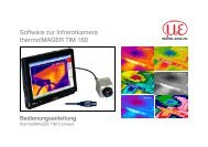
Abb. 1: Verkippte Streifen in einer Längsteilanlage<br />
Fig. 1: Tilted strips in a slitter<br />
Increasingly complex processing, optimisation<br />
of raw material costs or new standards<br />
mean there is a continually growing<br />
demand for sensor technology. Optical<br />
measuring techniques are becoming more<br />
and more important here. An important<br />
quality characteristic of semi-finished aluminium<br />
products is their thickness profile.<br />
Deviations occur mainly at the start of<br />
the processing chain in hot or cold rolling<br />
processes. In order to ensure that the nominal<br />
thickness is maintained, it is necessary<br />
to determine the instantaneous value of<br />
the control variable dynamically and precisely.<br />
This requires modern sensors.<br />
With conventional mechanical devices, thickness<br />
is determined by contact using a pincerlike<br />
arrangement at individual measuring<br />
points, whereby it is only possible with this approach<br />
to get a rough estimate of the thickness<br />
profile. Such devices are too slow for recording<br />
transverse or longitudinal thickness profiles<br />
during the production process and thus<br />
unsuitable. Furthermore, such techniques are<br />
often prone to wear and therefore interrupt<br />
production.<br />
Radiometric processes require radiation<br />
from a source of isotopes or X-rays that are<br />
absorbed by the sheet or plate being measured.<br />
The difference between the radiation trans<strong>mit</strong>ted<br />
and received is then converted into<br />
an average thickness.<br />
The process is strongly<br />
dependent, though, on<br />
the alloy and the condition<br />
of the material.<br />
The cost of radiation<br />
protection and ongoing<br />
safety inspections<br />
means high variable<br />
costs are associated<br />
with this method.<br />
If one wants a noncontact<br />
system that operates<br />
with a stand-off<br />
distance that is both<br />
(Photo Flender) production- and userfriendly<br />
and allows<br />
measurements to be carried out independently<br />
of the alloy, it is necessary to employ a precise<br />
geometric method of measurement based<br />
on the strip surface as the point of reference.<br />
This means using optical distance sensors coupled<br />
with laser triangulation.<br />
By employing laser line scanner systems,<br />
Micro-Epsilon Messtechnik has introduced an<br />
evolutionary new step in the technology of<br />
thickness measurement. Following a brief introduction<br />
to optical thickness measurement,<br />
the benefits of line sensors over point sensors<br />
will be discussed in this article and a technical<br />
solution is presented that has already proven<br />
itself in service at a customer’s plant.<br />
The advantages of an optical<br />
thickness-measuring technique<br />
When measuring the thickness of metal strip<br />
optically, a distance sensor is arranged on each<br />
side of the strip. The thickness is then the difference<br />
between the individual distances<br />
measured. However, the distance between the<br />
two sensors needs to be known and kept very<br />
constant. This means having a stable mechanical<br />
construction, either as a C- or O-shaped<br />
frame, and places particular demands on the<br />
positioning and calibration of the sensors and<br />
on compensation for deflection of the frame.<br />
At a measuring point, triangulation sensors<br />
determine the stand-off distance of the object<br />
2 ALUMINIUM · 11/2011
S P E CIAL<br />
ALUMINIUM ROLLING IND U STRY<br />
being measured very precisely by registering<br />
the positional shift of the spot from a detector<br />
positioned at an angle. Focal diameters of less<br />
than 100 µm are not uncommon. The stand-off<br />
distance can only be taken to be the average<br />
value over the whole spot. Consequently, it is<br />
desirable for the spot size to be small. Working<br />
against this is the effect of surface roughness,<br />
which can only be reduced by increasing<br />
the spot size. It therefore does not make sense<br />
to design the spot size to be arbitrarily small.<br />
If the strip is wavy or not plane positioned,<br />
pointwise measurement always results in a<br />
measuring error. One can only eliminate such<br />
so-called angle errors if one knows the position<br />
of the strip. Micro-Epsilon is concentrating<br />
here on a new innovation. The use of profile<br />
sensors rather than point sensors increases<br />
the information density and thus per<strong>mit</strong>s a<br />
significantly better optical measurement over<br />
the widest possible range of strip materials.<br />
Compared with point lasers, the measuring accuracy<br />
is also significantly better.<br />
Thickness measurement<br />
on slit strip in slitters<br />
There are often large vertical movements<br />
when processing cold-rolled strip, for example<br />
in slitters. However, when it comes to resolution<br />
and linearity, point sensors capable of<br />
covering a large measuring range are usually<br />
not capable of achieving the desired precision<br />
needed to monitor tolerances in accordance<br />
with EN 485-4. The reason for this is that point<br />
sensors only measure the value at a single<br />
point. With line sensors, though, lots of points<br />
are measured and furthermore these are recorded<br />
considerably more frequently. With<br />
the line sensor approach, a line of best fit can<br />
be drawn through the measured height profile.<br />
If one then measures the thickness, a much<br />
higher resolution can be achieved because<br />
this now results from the minimum change of<br />
two lines of best fit. If there is a stand-off distance<br />
of 190 mm and a measurement range of<br />
40 mm, suitable algorithms enable systems<br />
that use line scanners to measure linearities of<br />
± 5 µm. By comparison, if point sensors were<br />
to be used in this case, only linearities of ± 25<br />
µm could be achieved.<br />
With the slitters previously mentioned, an<br />
additional challenge is the changes to the position<br />
of the strip (tilting) that take place during<br />
the slitting operation (Fig. 1). In a slitter,<br />
it is above all the measurement of the individual<br />
webs after the cutter spindle that is of<br />
interest because the measured variable can<br />
be determined here for each individual web.<br />
With a point sensor, there is always an angle<br />
Die Vorteile der optischen<br />
Dickenmesstechnik<br />
Bei der optischen Dickenmessung von Metallband<br />
wird auf beiden Seiten des Bandes<br />
jeweils ein Distanzsensor angeordnet. Die<br />
Differenz aus den gemessenen Einzelabständen<br />
ist dann die Dicke. Allerdings muss der<br />
Abstand der beiden Sensoren zueinander<br />
bekannt und sehr konstant sein. Das impliziert<br />
eine stabile Mechanikkonstruktion, die<br />
entweder als C-Bügel oder als O-Rahmen<br />
ausgeführt, besondere Anforderungen hinsichtlich<br />
der Positionierung und Kalibrierung<br />
der Sensoren sowie der Kompensation einer<br />
Rahmendurchbiegung stellt.<br />
Triangulationssensoren er<strong>mit</strong>teln an einem<br />
Messpunkt sehr <strong>präzise</strong> einen Distanzwert<br />
zur Messgutoberfläche, in dem sie die Positionsverschiebung<br />
des Messfleckes auf einem<br />
winklig angeordneten Detektor registrieren.<br />
Fokusdurchmesser von kleiner 100 µm sind<br />
da keine Seltenheit. Der Abstand kann aber<br />
nur als <strong>mit</strong>tlerer Wert über den gesamten<br />
Messfleck angegeben werden. Folglich sind<br />
hier minimale Messfleckgrößen wünschenswert.<br />
Dem entgegen wirkt der Einfluss der<br />
Oberflächenrauigkeit, den man nur durch<br />
Messfleckvergrößerung reduziert. Es ist daher<br />
nicht sinnvoll, den Messfleck beliebig klein<br />
auszulegen.<br />
Welligkeiten oder Schräglagen des Bandes<br />
bedingen bei einer punktweisen Messung<br />
immer einen Messfehler. Diesen sog. Winkelfehler<br />
kann man nur eliminieren, wenn man<br />
die Bandlage erkennt. Micro-Epsilon setzt<br />
hier auf eine Innovation. Die Verwendung<br />
von Profilsensoren gegenüber Punktsensoren<br />
erhöht die Informationsdichte und lässt so<strong>mit</strong><br />
eine wesentlich bessere optische Messung<br />
auf unterschiedlichsten Bandmaterialien zu.<br />
Auch die Messgenauigkeit wird gegenüber<br />
dem Punktlaser signifikant verbessert.<br />
Dickenmessung an<br />
Spaltband in Längsteilanlagen<br />
Abb. 2: Messfehler aufgrund von Winkelfehlern bei punktförmigen Sensoren<br />
Fig. 2: Measuring error resulting from angle errors with point sensors<br />
Oft entstehen bei der Verarbeitung von<br />
Kaltband große vertikale Bewegungen, zum<br />
Beispiel in Längsteilanlagen. Punktsensoren,<br />
die einen großen Messbereich überwachen<br />
können, sind bezüglich Auflösung und Linearität<br />
jedoch meist nicht mehr in der Lage,<br />
die geforderte Präzision<br />
zu erreichen, die<br />
zur Überwachung der<br />
Toleranzen EN 485-4<br />
entsprechend notwendig<br />
ist. Dies ist da<strong>mit</strong><br />
zu erklären, dass bei<br />
Punktsensoren nur ein<br />
Messwert bzw. Punkt<br />
zur Verfügung steht.<br />
Mittels Liniensensoren<br />
werden jedoch<br />
viele Messwerte bzw.<br />
Punkte verwendet, die<br />
zudem <strong>mit</strong> beträchtlich<br />
höheren Frequenzen<br />
erfasst werden. Durch<br />
das gemessene Höhenprofil<br />
kann bei einem<br />
linearen Ansatz eine<br />
Ausgleichsgerade gelegt<br />
wird. Berechnet<br />
man jetzt die Dicke,<br />
kann eine viel höhere<br />
Auflösung erzielt werden,<br />
da diese nun durch die geringste Änderung<br />
zweier Ausgleichsgeraden resultiert. Mit<br />
Hilfe von geeigneten Algorithmen erreichen<br />
die Systeme <strong>mit</strong> Linienscannern bei einem<br />
Messspalt von 190 mm und einem Messbereich<br />
von 40 mm eine Linearität von ± 5 µm.<br />
Demgegenüber sind <strong>mit</strong> Punktsensoren für<br />
die genannten Bereiche nur Linearitäten von<br />
± 25 µm erreichbar.<br />
Eine weitere Herausforderung bei den bereits<br />
angesprochenen Längsteilanlagen sind<br />
die Lageveränderungen im Bandlauf (Verkippungen),<br />
denen die produzierten Ringe durch<br />
den Spaltvorgang unterworfen sind (Abb. 1).<br />
In einer Spaltanlage ist vor allem die Messung<br />
der einzelnen Streifen hinter der Messerwelle<br />
interessant, da hier die Messgrößen für jeden<br />
ALUMINIUM · 11/2011 3
ALUMINIUMWALZ IND U STRI E<br />
einzelnen Ring bestimmt werden können. Bei<br />
einem Punktsensor entsteht auch bei perfekter<br />
Ausrichtung der Sensoren immer ein<br />
Winkelfehler gemäß Abb. 2. Bei Systemen<br />
<strong>mit</strong> Liniensensoren kann die Verkippung<br />
des Materials durch die oben beschriebenen,<br />
Ausgleichsgeraden er<strong>mit</strong>telt und kompensiert<br />
werden. Da<strong>mit</strong> ist auch in diesem, für die Dickenmessung<br />
schwierigem Umfeld eine exakte<br />
Messung möglich.<br />
Anforderungen an die Stabilität<br />
Beispiel-Spezifikation einer<br />
Komplettmessung für Spaltband<br />
Dicke: 1-5 mm<br />
Messspalt: 300 mm<br />
Linearität: ± 5 µm<br />
Ausgabe: Dickenprofil<br />
Breite: Linearität: ± 100 µm<br />
Ausgabe: max. 25 Streifen<br />
Geschwindigkeit: Anlage: max. 580 m/min<br />
Signalübergabe für Synchronisation der<br />
Messerwelle<br />
Länge: Coillänge, Bandlänge<br />
Linearität ± 0,05%<br />
Bei der oben beschriebenen, beidseitigen Anordnung<br />
der Sensoren kommt der Konstanz<br />
des Sensorabstands eine besondere Bedeutung<br />
zu. Zwei unterschiedliche Konstruktionsprinzipien<br />
stehen dabei zur Verfügung,<br />
die aufgrund ihrer Form als C-Bügel oder<br />
O-Rahmen bezeichnet werden. Beim C-Bügel<br />
(Abb. 3) sind die Sensoren am äußeren<br />
Ende der Schenkel angebracht und fest <strong>mit</strong><br />
dem Rahmen verbunden, der auf einer Seite<br />
geöffnet ist, um in das Band einzufädeln.<br />
C-Bügel sind vorteilhaft für Anwendungen<br />
an schmalen Bändern (z. B. bis zu 800 mm<br />
Breite) ausgelegt, da <strong>mit</strong> steigender Maultiefe<br />
die Schwingungsanfälligkeit des oberen<br />
Schenkels steigt. Die erforderliche Maultiefe<br />
ergibt sich bei Messung in Band<strong>mit</strong>te aus<br />
der halben Bandbreite zuzüglich einer Reserve<br />
für das seitliche Schwärmen der Bandkanten.<br />
Bei der Ausführung des C-Bügels als ein traversierendes<br />
System wird ausreichend Platz<br />
neben der Linie benötigt, um den Rahmen bis<br />
auf die Nullposition zu fahren.<br />
Da zeitvariante thermische Änderungen<br />
auf den Rahmen einwirken, ist es wichtig, geeignete<br />
Wege zu finden, die Maulweite konstant<br />
zu halten. Die Systeme der Micro-Epsilon<br />
Messtechnik setzen hier auf das Prinzip der<br />
iterativen Kalibration. Diese hat gegenüber<br />
den deutlich höheren Kosten eines temperaturinvarianten<br />
Rahmens wesentliche Vorteile.<br />
Gerade in heiße Umgebung setzen die Temperaturen<br />
nicht nur der Mechanik, sondern<br />
auch der Elektronik zu. Für das Erreichen<br />
einer dauerhaften Stabilität müssten dann die<br />
Elektroniken beheizt oder gekühlt werden,<br />
um sie unabhängig von der Temperatur in der<br />
Produktionsumgebung zuverlässig und <strong>präzise</strong><br />
betreiben zu können.<br />
Erfasst man allerdings die exakte Maulweite<br />
in entsprechenden Intervallen durch Kalibrieren,<br />
kann <strong>mit</strong> einer wesentlich einfacheren<br />
Konstruktion gearbeitet werden. Automatisiert<br />
man die Kalibration, entsteht der Vorteil,<br />
jederzeit <strong>mit</strong> Hilfe eines Kalibrierstücks (Kalibriernormal)<br />
einen Nachweis der Prüf<strong>mit</strong>telfähigkeit<br />
der Anlage durchführen zu können<br />
Abb. 3: C-Rahmensystem bei AMAG Ranshofen<br />
Fig. 3: C-shaped frame system at AMAG Ranshofen<br />
bzw. deren ordnungsgemäßen Zustand zu dokumentieren.<br />
Neben C-bügelförmigen Systemen bietet<br />
Micro-Epsilon auch Lösungen auf der Basis<br />
eines O-Rahmens an (Abb. 4). Diese sind<br />
vorwiegend für breite Bänder ausgelegt und<br />
können auch das komplette Dickenprofil in<br />
der Breite erfassen.<br />
Aus der größeren Breite ergibt sich unter<br />
anderem auch durch die oben zitierten thermischen<br />
Anforderungen ein komplexer Aufbau.<br />
Die Messköpfe sind jeweils an einer horizontalen<br />
Achse befestigt, und bewegen sich<br />
quer zur Produktions- bzw. Transportrichtung<br />
des Bandes. Praxistests zeigten, dass bereits<br />
Rahmen <strong>mit</strong> einer Breite von 2 m bei Temperaturschwankungen<br />
von ± 20 °C eine Abweichung<br />
des Sensorspalts (Maulweite) von 400<br />
µm aufwiesen. Um dies zu kompensieren, setzt<br />
Micro-Epsilon ein zum Patent angemeldetes<br />
System <strong>mit</strong> einem temperaturinvarianten<br />
mechanischen Kompensationsrahmen ein.<br />
Neuartig ist, dass den Messsensoren zugeerror<br />
as shown in Fig. 2 even if the sensor is<br />
fitted perfectly. In systems with line sensors,<br />
the tilting of the material can be determined<br />
as described above using lines of best fit and<br />
compensated accordingly. It is therefore also<br />
possible to obtain a precise measurement of<br />
the thickness even under such difficult conditions.<br />
Stability requirements<br />
With sensors arranged on both sides as described<br />
above, maintaining a constant standoff<br />
distance takes on a particular significance.<br />
Two different design principles are available,<br />
which because of their shape are referred to as<br />
either C- or O-shaped frames. With C-shaped<br />
frames (Fig. 3), the sensors<br />
are positioned at the<br />
outermost ends of the<br />
arms and connected tightly<br />
to the frame, which is<br />
open on one side in order<br />
to be able to feed it round<br />
the strip. C-shaped frames<br />
are preferably used for<br />
applications involving<br />
narrow strip (e. g. up to<br />
800 mm wide) because<br />
with increasing depth of<br />
the ‘jaws’ the upper arm<br />
becomes increasingly susceptible<br />
to oscillation. In<br />
the case of measurement<br />
in the middle of the strip,<br />
the necessary jaw depth<br />
is given by half the strip<br />
width plus provision for the sideways movement<br />
of the strip edges. If the C-shaped frame<br />
is designed as a traversing unit, there needs to<br />
be sufficient space next to the line to move the<br />
line into the zero position.<br />
There are time-dependent thermal changes<br />
Typical specification for the<br />
complete measurement of slit strip<br />
Thickness: 1-5 mm<br />
Stand-off distance: 300 mm<br />
Linearity: ± 5 µm<br />
Output: thickness profile<br />
Width: linearity: ± 100 µm<br />
Output: max. 25 strips<br />
Speed: unit: max. 580 m/min<br />
Signal transmission for synchronisation of the<br />
cutter spindle<br />
Length: coil length, strip length<br />
Linearity: ± 0.05%<br />
4 ALUMINIUM · 11/2011
S P E CIAL<br />
ALUMINIUM ROLLING IND U STRY<br />
acting on the frame so it is important to find<br />
suitable ways to keep the width of the jaws<br />
constant. Systems supplied by Micro-Epsilon<br />
rely on the principle of iterative calibration.<br />
This offers significant benefits compared with<br />
the markedly higher costs of a temperatureinvariant<br />
frame. Particularly in hot environments,<br />
temperature affects not only the mechanics<br />
but also the electronics. In order to<br />
achieve permanent stability, the electronics<br />
would then have to be heated or cooled to<br />
make it reliable and accurate regardless of the<br />
temperature in the production environment.<br />
If one calibrates the jaw opening at suitable<br />
intervals to ensure it is exact, one can work<br />
with a much simpler design. If the calibration<br />
is automated, one has the advantage that with<br />
the aid of a calibration piece (calibration standard)<br />
one can verify the capability of the unit’s<br />
measuring system at any time or document<br />
that it is in proper working order.<br />
In addition to C-shaped frame systems, Micro-Epsilon<br />
also offers solutions based on O-<br />
shaped frames (Fig. 4). These are mainly used<br />
with wide strip and can also measure the complete<br />
thickness profile over the whole width.<br />
Amongst others, larger widths also lead to<br />
a more complex construction because of the<br />
thermal requirements mentioned above. The<br />
measuring heads are each attached to a horizontal<br />
shaft and move in a direction transverse<br />
to the direction of processing or transport of<br />
the web. Practical tests have shown that even<br />
with a frame that is 2 m wide the stand-off<br />
distance (jaw width) will deviate by 400 µm if<br />
there are temperature fluctuations of ± 20°C.<br />
To compensate for this, Micro-Epsilon is now<br />
employing a system with a temperature-invariant<br />
mechanical compensation frame for<br />
which a patent has been applied. Novel is<br />
that the compensation sensors assigned to the<br />
measuring sensors measure the position of the<br />
measuring sensor relative to the horizontal<br />
beam of the compensation frame. If the position<br />
of the sensor moves vertically as a result<br />
of thermal effects, the compensation sensor<br />
measures the displacement and the analytical<br />
software adds or subtracts this change to or<br />
from the measured stand-off distance. From a<br />
virtual point of view, the transitory jaw width<br />
thus remains constant (Fig. 5). In addition to<br />
this very efficient procedure, mechanical or<br />
thermal changes in the mountings of the sensor<br />
housing are compensated for by means of<br />
iterative calibration.<br />
Quality inspection of strip<br />
Besides simple thickness measurement, many<br />
strip plants now demand quality inspection<br />
ordnete Kompensationssensoren die Position<br />
des Messsensors gegenüber dem horizontalen<br />
Gurt des Kompensationsrahmens messen.<br />
Verschiebt sich die Position des Sensors<br />
aufgrund thermischer Einwirkung vertikal,<br />
so misst der Kompensationssensor diese<br />
Verschiebung <strong>mit</strong> und die Analysesoftware<br />
addiert, bzw. subtrahiert diese Änderung<br />
zum Messspalt. Da<strong>mit</strong> bleibt die momentane<br />
Maulweite virtuell gesehen konstant (Abb. 5).<br />
Zusätzlich zu diesem bereits beschriebenen<br />
sehr effizienten Verfahren werden die mechanischen<br />
oder thermischen Änderungen in<br />
den Aufhängungen der Sensorgehäuse <strong>mit</strong>tels<br />
iterativer Kalibration kompensiert.<br />
Komplettprüfung von Bändern<br />
Abb. 4: O-Rahmensystem<br />
zur <strong>Banddickenmessung</strong><br />
Fig. 4: O-shaped frame system<br />
for measuring sheet thickness<br />
Neben einer reinen Dickenmessung ist in vielen<br />
Bandanlagen eine Komplettprüfung gefordert.<br />
High-Tech-Lichtschranken unterstützen<br />
hier die Profilsensoren. Sie übernehmen die<br />
Aufgabe der Breitenmessung und ggf. Kantendetektion<br />
einzelner Streifen nach dem Spalten.<br />
Alle Messdaten können zur Dokumentation<br />
des Metallbandes verwendet werden.<br />
Die Messdaten „Dicke“ und „Profil“ werden<br />
online einer genauen Position auf dem Band<br />
zugeordnet. Die Bandposition wird ebenfalls<br />
berührungsfrei erfasst. Zum Einsatz kommt<br />
hier die bewährte ASCOspeed Technologie,<br />
die im Kaltbandbereich vielerorts einen guten<br />
Namen genießt, wurden doch Walzwerke und<br />
Bandanlagen durch den Maschinenbauer oft<br />
<strong>mit</strong> dieser Technik ausgerüstet.<br />
Das ASCOspeed erfasst die Bandgeschwindigkeit<br />
deutlich sicherer als bisher die Geber<br />
an den Walzen oder separate Messräder.<br />
Schlupf und betriebsbedingte Abnutzung werden<br />
durch die berührungsfreie Arbeitsweise<br />
vermieden (Abb. 6). Die aktuelle Bandlänge<br />
wird <strong>präzise</strong> erfasst und bildet die<br />
Basis für das Coilprotokoll.<br />
Die Längengenauigkeit<br />
beträgt<br />
0,05% und sichert eine spätere leichte<br />
Auffindung von außermaßigen Bandabschnitten,<br />
zum Beispiel durch Walzenschlag. Bei<br />
der Einbindung der Profilmessung in eine<br />
Spaltanlage können alle Streifen in Breite und<br />
Profil gemessen werden. Jeder Streifen bekommt<br />
ein eigenes Messprotokoll. So werden<br />
nachfolgende Prozessschritte der Qualitätssicherung<br />
besser unterstützt. Verwendet wird<br />
die Anlage in Servicezentren zur Eingangskontrolle<br />
von Warmband vor dem Kaltwalzen<br />
sowie nach dem Spalten der Coils. Die Anlage<br />
ist im oberen Leistungssegment für Systeme<br />
zur Messung der Metallbandgeometrie zu<br />
sehen. Bekannte bisherige Verfahren werden<br />
da<strong>mit</strong> wirkungsvoll substituiert. Die Wirtschaftlichkeit<br />
der Investition in eine Messung<br />
<strong>mit</strong> <strong>Laser</strong>scannern liegt in der nunmehr detaillierten<br />
Kenntnis der realen Bandtoleranzen<br />
bis hin zur Dokumentation jedes einzelnen<br />
Streifens für den Endkunden.<br />
Einsatzerfahrungen beim Betreiber<br />
In der Zusammenarbeit <strong>mit</strong> Aluminiumherstellern<br />
kann die Micro-Epsilon-Gruppe auf<br />
langjährige gute Erfahrung verweisen. Besonders<br />
<strong>mit</strong> der AMAG Ranshofen gab es in der<br />
Vergangenheit viele gemeinsame Projekte.<br />
Die AMAG stützt sich bei der Fertigung<br />
von Bändern, Blechen und Platten auf über<br />
70 Jahre Erfahrung <strong>mit</strong> dem Werkstoff Aluminium.<br />
Die Qualitätssicherungssysteme des<br />
Unternehmens erfüllen die hohen Ansprüche<br />
der Luftfahrt- und Automobilindustrie.<br />
AMAG versteht sich als Anbieter für Spezialprodukte<br />
<strong>mit</strong> hohem Kundennutzen. Diese<br />
Ansprüche erfordern natürlich auch eine<br />
entsprechende Überwachung und Qualitätssicherung<br />
hinsichtlich Materialdicken bzw.<br />
Bandprofilen.<br />
Am Standort Ranshofen sind so<br />
ziemlich alle bisher üblichen<br />
Varianten an Dickenmesssystemen<br />
von Isotopenstrahler,<br />
mechanischer Dickenmessungen<br />
bis hin zu optischen<br />
Systemen im Einsatz. Aktuell<br />
werden intensiv die Kapazitäten<br />
im Finalbereich<br />
(Scherenanlagen) ausgebaut.<br />
Im Zuge dieser Investitionen<br />
wurde nun auch eine<br />
moderne Dickenmessung für<br />
die jeweiligen Längs- und<br />
Querteilanlagen gesucht. Die<br />
bisher verwendeten mechanischen<br />
Systeme <strong>mit</strong> ihren Nachteilen<br />
bezüglich Oberflächenbeschädigung,<br />
Anfälligkeit und<br />
ALUMINIUM · 11/2011 5
ALUMINIUMWALZ IND U STRI E<br />
begrenzte Messbereiche (nur Randbereich)<br />
entsprachen nicht mehr den Anforderungen.<br />
Versuchsaufbauten <strong>mit</strong> dem <strong>Laser</strong>messsystem<br />
von Micro-Epsilon waren so viel versprechend,<br />
dass die Entscheidung sehr rasch<br />
getroffen werden konnte. Unter anderem<br />
wurden auch Messungen in der Fertigung von<br />
Trittblechen durchgeführt. Diese Produktgruppe<br />
war zwar nicht der ursprüngliche Auslöser<br />
für den Bedarf, der resultiert viel mehr<br />
aus dem Bereich Automobilindustrie, zeigte<br />
aber die Leistungsfähigkeit, Flexibilität und<br />
den weiten Einsatzbereich der Micro-Epsilon-<br />
Technik.<br />
Aktuell befindet sich ein C-Bügel in der<br />
Testphase an einer bestehenden Querteilanlage<br />
(Abb. 3). Basierend auf den Erfahrungen<br />
dort, soll im ersten Quartal des nächsten Jahres<br />
ein O-Rahmen für eine bis dahin gelieferte<br />
neue Längsteilanlage in Betrieb genommen<br />
werden.<br />
Für AMAG war es besonders wichtig, die<br />
unterschiedlichsten Oberflächen und Reflexionsgrade<br />
<strong>mit</strong> einem einzigen System abzudecken.<br />
Die Erfahrungen bisher decken sich<br />
<strong>mit</strong> den Versuchsergebnissen und zeigen, dass<br />
Micro-Epsilon die richtige Lösung für Ranshofen<br />
hat.<br />
Axes: Messspalt-Geometrie – Stand off geometry, Temperatur – Temperature (° C), Messspalt – Change in<br />
stand off (µm), Zeit – Time (min); Curves: green – Change in temperature (°C), red – Change in virtual stand<br />
off (µm), blue – Change in real stand off (µm)<br />
Fig. 5: Changes in stand-off distance as a result of thermal effects<br />
Abb. 5: Veränderung des Messspalts, bei thermischer Einwirkung<br />
Zusammenfassung<br />
Eine neue Evolutionsstufe in der optischen<br />
Dickenmesstechnik ist der Einsatz von <strong>Laser</strong>linienscannern<br />
in Systemen auf C- und O-<br />
Rahmenbasis der Micro-Epsilon Messtechnik,<br />
Ortenburg. Die Verwendung von Profilsensoren<br />
gegenüber Punktsensoren erhöht<br />
die Informationsdichte und lässt so<strong>mit</strong> eine<br />
wesentlich bessere optische Messung auf unterschiedlichsten<br />
Bandmaterialien zu. Auch<br />
die Messgenauigkeit wurde durch die <strong>Laser</strong>-<br />
Linien gegenüber dem Punktlaser signifikant<br />
verbessert und erreichen zum Beispiel bei<br />
einem Messspalt von 190 mm und einem<br />
Messbereich von 40 mm eine Linearität von<br />
besser ± 5 µm. Bei Systemen <strong>mit</strong> Liniensensoren<br />
kann die Verkippung des Materials<br />
kompensiert werden. Durch die Erfassung der<br />
exakten Maulweite wird <strong>mit</strong> einer wesentlich<br />
einfacheren Konstruktion gearbeitet. Mittels<br />
automatischer Kalibrierung hat der Betreiber<br />
die Möglichkeit, jederzeit <strong>mit</strong>hilfe eines<br />
Kalibrierstücks (Kalibriernormal) einen Nachweis<br />
der Prüf<strong>mit</strong>telfähigkeit der Anlage durchzuführen,<br />
bzw. deren ordnungsgemäßen Zustand<br />
zu dokumentieren.<br />
Bei der Einbindung der Profilmessung in<br />
eine Spaltanlage können alle Streifen in Breite<br />
und Profil gemessen werden. Verwendung<br />
findet die Technik in Servicezentren zur Eingangskontrolle<br />
von Warmband vor dem Kaltwalzen<br />
sowie für eine Komplettprüfung von<br />
Spaltband.<br />
Die Zufriedenheit der Kunden <strong>mit</strong> den bereits<br />
im Einsatz befindlichen Anlagen dokumentiert<br />
die Leistungsfähigkeit der beschriebenen<br />
Dickenmessung eindrucksvoll.<br />
Auch am Standort Ranshofen, wo die Betreiber<br />
bei Neubestellungen von Scherenanlagen<br />
sowie auch bei bestehenden Anlagen<br />
zukünftig die steigenden Qualitätsansprüche<br />
erfüllen müssen, wird es noch einige Aufgaben<br />
für Micro-Epsilon geben.<br />
Literatur<br />
Siehe Angaben in englischer Version.<br />
Autoren<br />
Dipl. Inform.-Univ. Achim Sonntag, Leiter<br />
Geschäftsbereich Systemtechnik, Micro-Epsilon<br />
Messtechnik GmbH & Co. KG.<br />
Dr.-Ing. Klaus Christofori, Produktmanager<br />
ASCOspeed, Micro-Epsilon Optronic GmbH.<br />
Dipl.-Ing. (FH) Siegfried Kalhofer, Produktmanager<br />
Systemtechnik, Micro-Epsilon Messtechnik GmbH<br />
& Co. KG.<br />
Ing. Markus Leitner, Betriebsleiter Finalisieren,<br />
AMAG rolling GmbH, Ranshofen.<br />
of the strip thickness. High-tech light barriers<br />
provide support of the profile sensors here.<br />
They take over the job of width measurement<br />
and possibly detecting the edges of the individual<br />
strips after slitting. All measurements<br />
made can be used to document the metal strip.<br />
Thickness and profile are assigned to an exact<br />
position on the strip online. The position of<br />
the strip is also determined without contact.<br />
Tried and tested ASCOspeed technology is<br />
employed; this enjoys a good reputation at<br />
many rolling mills and strip plants in the coldrolled<br />
strip area where machine manufacturers<br />
have often installed this technology.<br />
ASCOspeed measures the speed of the strip<br />
significantly more reliably than the trans<strong>mit</strong>ter<br />
on the rolls or separate measuring wheels.<br />
By means of non-contact working principle,<br />
slippage and operational wear are avoided<br />
(Fig. 6). The instantaneous length of the strip<br />
is measured precisely and forms the basis for<br />
the coil production log. The accuracy of length<br />
is 0.05% and ensures that it is easy later to find<br />
off-size sections of strip, for example as a result<br />
of eccentricity of the rolls. By incorporating<br />
measurement of the profile in a slitter, the<br />
width and profile of all strips can be measured.<br />
Each strip has its own measurement record.<br />
This provides improved support for the quality<br />
assurance of subsequent process steps. The<br />
unit is used in service centres to inspect incom-<br />
6 ALUMINIUM · 11/2011
S P E CIAL<br />
ALUMINIUM ROLLING IND U STRY<br />
ing hot-rolled strip, prior to cold rolling and<br />
after slitting the coils. The unit is in the upper<br />
performance class for systems that measure<br />
the geometry of metal strip. It is an effective<br />
substitute for the well-known processes used<br />
until now. The economic benefit of investing<br />
in laser scanners to carry out measurements is<br />
the fact that one has detailed knowledge of the<br />
actual strip tolerances through to documentation<br />
of each individual strip for the end user.<br />
Experience in use at a production plant<br />
The Micro-Epsilon group has had good experience<br />
working with aluminium manufacturers<br />
going back many years. There have been<br />
many joint projects in the past, especially with<br />
AMAG Ranshofen.<br />
ing system for its slitters and cut-to-length<br />
lines. The mechanical systems previously used<br />
were disadvantageous with respect to surface<br />
damage, vulnerability and li<strong>mit</strong>ed area of<br />
measurement (only the areas near the edge)<br />
and no longer met the company’s requirements.<br />
Test constructions using the laser measuring<br />
system from Micro-Epsilon were so promising<br />
that a decision could be reached very<br />
quickly. Amongst other things, measurements<br />
were also carried out during the manufacture<br />
of tread plate. Although it was originally intended<br />
to meet demand from the automotive<br />
industry and not from this product group, it<br />
nevertheless demonstrated the capability,<br />
flexibility and the broad field of application<br />
of Micro-Epsilon technology.<br />
thickness-measuring technology. The use of<br />
profile sensors instead of point sensors increases<br />
the information density and thus allows<br />
a significantly better optical measurement<br />
to be made on the most varied range of<br />
strip materials. Compared with point lasers,<br />
line lasers also improve the measuring accuracy<br />
significantly and with a stand-off distance<br />
of 190 mm and a measuring range of 40 mm<br />
achieve a linearity of better than ± 5 µm. One<br />
can compensate for tilting of the material<br />
when line sensors are employed. By determining<br />
the exact width of the jaws, one can use<br />
a markedly simpler construction. Automatic<br />
calibration gives the operator the opportunity<br />
to verify the capability of the unit’s measurement<br />
system at any time or document that it<br />
is in proper working order with the aid of a<br />
calibration piece (calibration standard).<br />
If profile measurement is incorporated in a<br />
slitting line, the width and profile of all strips<br />
can be measured. The technology is used in<br />
service centres to inspect incoming hot-rolled<br />
strip prior to cold rolling and for complete<br />
testing of the slit strip.<br />
Customer satisfaction with the units already<br />
in use documents the capability of the<br />
method of measuring thickness described.<br />
There will also be further business opportunities<br />
for Micro-Epsilon at the Ranshofen<br />
plant, where the operator will have to meet<br />
increasing quality demands in future for<br />
shears as well as existing plant.<br />
Literature<br />
Abb. 6: Komplettvermessung <strong>mit</strong> Längenprotokoll durch ASCOspeed<br />
Fig. 6: Complete measurement with record of length using ASCOspeed<br />
AMAG has over 70 years’ experience in the<br />
production of aluminium strip, sheet and plate.<br />
AMAG’s quality assurance systems meet the<br />
high demands of the aerospace and automotive<br />
industries. The company regards itself as a<br />
supplier of special products with a high level of<br />
customer benefits. Of course, these demands<br />
also require suitable monitoring and quality<br />
assurance with respect to material thicknesses<br />
and / or strip profiles.<br />
Nearly all the usual types of thicknessmeasuring<br />
system have been used at the<br />
company’s Ranshofen plant in the past, from<br />
isotope radiators, via mechanical thickness<br />
measurement through to optical systems. The<br />
company is currently markedly expanding its<br />
capacity in the finishing area (slitting lines).<br />
As part of these investments the company was<br />
also looking for a modern thickness measur-<br />
Currently, a C-shaped frame is undergoing<br />
testing in an existing cut-to-length line (Fig.<br />
3). Based on the experience gained there, it<br />
is planned to supply and commission an O-<br />
shaped frame for a new slitter due to be installed<br />
in the first quarter of 2012.<br />
It was particularly important for AMAG<br />
to cover as varied a range of different surfaces<br />
and reflectivities as possible with a single system.<br />
The experience gained thus far has confirmed<br />
the test results and shows that Micro-<br />
Epsilon has the right solution for Ranshofen.<br />
Summary<br />
Systems that use laser line scanners in C-shaped<br />
and O-shaped frames supplied by Micro-Epsilon<br />
Messtechnik of Ortenburg, Germany,<br />
mark a new step in the evolution of optical<br />
Flender<br />
[1] Kalhofer, S.; Hofmann, F.; Herrmann, H.-J.;<br />
Onderka, B.; Christofori, K.: Inline Dimension and<br />
Profile Measurement of Aluminium Plates for Hot<br />
Rolling. APT Aluminium Process Technology V (1)<br />
(Feb. 2008) 23-26.<br />
[2] Gaczensky, F.; Radomski, M.-M,.; Rink, C.;<br />
Christofori, K.: New aspects for measuring the<br />
quality of aluminium semis. International ALUMIN-<br />
IUM Journal, 85 (2009) (11) 44-51.<br />
[3] Christofori, K.; Rümmler, Th.: Non-contact<br />
speed measurement helps to ensure stable strip<br />
quality. International ALUMINIUM Journal 86<br />
(2010) (10) 46-51.<br />
Authors<br />
Dipl. Inform.-Univ. Achim Sonntag, manager<br />
System Technology, Micro-Epsilon Messtechnik<br />
GmbH & Co. KG.<br />
Dr.-Ing. Klaus Christofori, product manager<br />
ASCOspeed, Micro-Epsilon Optronic GmbH.<br />
Dipl.-Ing. (FH) Siegfried Kalhofer, product manager<br />
System Technology, Micro-Epsilon Messtechnik<br />
GmbH & Co. KG.<br />
Ing. Markus Leitner, plant manager Finishing,<br />
AMAG rolling GmbH, Ranshofen.<br />
ALUMINIUM · 11/2011 7
ALUMINIUMWALZ IND U STRI E<br />
MICRO-EPSILON Messtechnik GmbH & Co. KG<br />
Königbacher Str. 15<br />
94496 Ortenburg<br />
Germany<br />
Tel.: +49 8542 168-0<br />
Fax: +49 8542 168-90<br />
Email: info@micro-epsilon.de<br />
www.micro-epsilon.de<br />
8 ALUMINIUM · 11/2011