AM54 - Fluid Process Control Corporation
AM54 - Fluid Process Control Corporation
AM54 - Fluid Process Control Corporation

You also want an ePaper? Increase the reach of your titles
YUMPU automatically turns print PDFs into web optimized ePapers that Google loves.
Data Sheet<br />
D-FV-<strong>AM54</strong>_1<br />
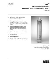
Field IT<br />
Variable Area Flowmeters<br />
Series <strong>AM54</strong><br />
n<br />
n<br />
n<br />
n<br />
n<br />
n<br />
n<br />
n<br />
n<br />
Modular Indicator Design allows<br />
upgrading to alarm or transmitter<br />
functions<br />
Explosion Proof Design of secondary for<br />
use in hazardous areas<br />
Digital Display Option for totalization and<br />
rate of flow<br />
Digital Communication via HART<br />
protocol<br />
Straight through design eliminates<br />
elbows and recessed or stagnant areas.<br />
Short face-to-face dimension saves<br />
space and makes retrofitting easier.<br />
Non-protruding float rods eliminate<br />
need for special piping at both ends.<br />
Easy float replacement without replacing<br />
the entire meter body.<br />
All Teflon ® float and Teflon ® lining<br />
option for corrosive fluids applications.<br />
Series <strong>AM54</strong><br />
Armored VA Meter
Variable Area Flowmeters<br />
Armored Variable Area Flowmeters- Series <strong>AM54</strong><br />
Variable Area Flowmeters<br />
Series <strong>AM54</strong><br />
The Series <strong>AM54</strong> is an all metal flow-through variable<br />
area flowmeter designed to measure the flow rates of<br />
liquids, gases or steam in pipe sizes from 1/2” to 4”.<br />
The <strong>AM54</strong> is particularly suited for the process industries<br />
such as in the Chemical, Pharmaceutical and the<br />
Food industries when aggressive or opaque fluids are<br />
to be metered or in those applications where glass meter<br />
tube flowmeters cannot be installed because of safety<br />
considerations. They are indispensable where high<br />
pressure and/or high temperature operating conditions<br />
exist.<br />
The float is magnetically coupled to either 1) an indicator<br />
alone; 2) to an indicator along with electronic (4 to<br />
20 mA) output transmission; or 3) to an indicator with<br />
electronic alarm capabilities. The meter body is constructed<br />
of AISI Type 316-Ti stainless steel for superior<br />
corrosion resistance in a variety of harsh industrial fluids.<br />
For added corrosion resistance, the meter can be<br />
supplied with all wetted parts lined with Teflon ® .<br />
Engineering Specifications<br />
Materials of Construction<br />
Meter Tube:<br />
Flanges:<br />
Stainless steel AISI Type 316-Ti<br />
(UNS31635). Teflon ® lining optional.<br />
Stainless steel AISI Type 316-Ti<br />
(UNS31635). Teflon ® lining<br />
optional.<br />
Float: Stainless steel AISI Type 316-Ti<br />
(UNS31635), Hastelloy C float<br />
head optional, all Teflon ® optional.<br />
O-Ring: Viton ® for 1/2" meter only; Viton ®<br />
for gas damping options. Other<br />
materials optional.<br />
Secondary Housing: Aluminum powder coated.<br />
Secondary Gasket:<br />
Secondary Window:<br />
Buna N<br />
Safety Glass<br />
Performance<br />
D-FV-<strong>AM54</strong>_1<br />
Accuracy:<br />
± 1.6% of full scale for unlined meters.<br />
± 2.5% of full scale for TEFLON lined meters.<br />
±1% of full scale optional with calibration for all<br />
meters.<br />
Range: 10:1<br />
Repeatability: 0.25% of full scale<br />
Scales: Percent or direct reading<br />
Connections<br />
Flanges:<br />
ANSI Class 150 raised face, standard<br />
ANSI Class 300 & 600 raised face,<br />
optional.<br />
Other flange variations upon request.<br />
Environmental Rating:<br />
Indicator Only: NEMA 4x / IP 67<br />
Indicator w/Alarms: NEMA 4x / IP 67 for meter.<br />
Relay amplifier must be remote mounted in<br />
suitable enclosure in nonhazardous area.<br />
Indicator w/Transmitter: NEMA 4x / IP 67<br />
Hazardous Area Approvals:<br />
Factory Mutual (FM)<br />
Explosion Proof: Class I, Div. 1, Groups A,B,C, & D<br />
(Note: Groups A&B require conduit seal<br />
within 18” of Instrument)<br />
Dust Ignition Proof: Class II, Div. 1,<br />
Groups E, F & G<br />
Intrinsically Safe: Class I, Div. 1,<br />
Groups A, B, C & D<br />
Non-Incendive: Class I, Div. 2, Groups A, B, C & D<br />
Canadian Standards Association<br />
Explosion Proof: Class I, Div. 1, Groups B, C & D<br />
(Note: Group B requires conduit seal<br />
within 18” of instrument)<br />
Dust Ignition Proof: Class II, Div. 1,<br />
Groups E, F & G<br />
Intrinsically Safe: Class I, Div. 1,<br />
Groups A, B, C & D<br />
Non-Incendive: Class I, Div.2, Groups A, B, C & D<br />
*Maximum temperature for Teflon lined meters.<br />
Teflon ® is a registered trademark of E.I. DuPont Co.<br />
2
Variable Area Flowmeters<br />
Armored Variable Area Flowmeters- Series <strong>AM54</strong><br />
D-FV-<strong>AM54</strong>_1<br />
Maximum Design Pressure:<br />
Temperature Pressure Rating psig (kPa ga)<br />
°F °C 150 lb. 300 lb.<br />
100 38 275 (1896) 720 (4964)<br />
200 93 235 (1620) 610 (4206)<br />
260 125* 220 (1516) 570 (3930)<br />
300 149 210 (1448) 545 (3757)<br />
400 204 190 (1310) 495 (3413)<br />
500 260 170 (1172) 460 (3171)<br />
600 316 140 (965) 435 (2999)<br />
Temperature Ranges<br />
Allowable fluid temperature: (T F<br />
)<br />
• -55ºC to +420ºC Standard (-67ºF to 788ºF)<br />
-20 to +125ºC for PTFE - Liner<br />
(-4ºF to 260ºF)<br />
• Allowable ambient temperature: (T A<br />
)<br />
-40 to +100ºC (-40ºF to 212ºF)<br />
For General Purpose Applications Only (for Hazardous Applications, See Page 8)<br />
<strong>AM54</strong>031-32/71-74, Insulated<br />
Max. <strong>Fluid</strong> Temperature<br />
T A<br />
ºC<br />
120<br />
110<br />
100<br />
<strong>AM54</strong>_71/74,Standard<br />
90<br />
<strong>AM54</strong>31-32,Standard<br />
80<br />
70<br />
60<br />
50<br />
40<br />
30<br />
20<br />
10<br />
0<br />
-10<br />
-20<br />
-30<br />
-40<br />
-50<br />
-60<br />
-100 -50 0 50 100 150 200 250 300 350 400 450<br />
T A<br />
ºC<br />
T A<br />
ºC<br />
120<br />
110<br />
100<br />
90<br />
80<br />
70<br />
60<br />
50<br />
40<br />
30<br />
20<br />
10<br />
0<br />
-10<br />
-20<br />
-30<br />
-40<br />
-50<br />
<strong>AM54</strong>031-32/71-74<br />
Max. <strong>Fluid</strong> Temperature<br />
<strong>AM54</strong>_72-74,Standard<br />
<strong>AM54</strong>_31-32,Standard<br />
-60<br />
-100 -50 0 50 100 150 200 250 300 350 400 450<br />
T A<br />
ºC<br />
Gas Damping<br />
Used for pulsating or unstable flows and to<br />
avoid compression oscillations (float bounce)<br />
when metering gases at low pressures.<br />
Unit Weight (Approx.), pounds (kg)<br />
TUBE SIZE<br />
Model Flange 1/2” 1” 2” 3” 4”<br />
Installation Lengths 250 mm 250 mm 250 mm 250 mm<br />
<strong>AM54</strong>37 150 lb 8.6 (3.9) 12.8 (5.8) 23.6 (10.7) 35 (15.9) 75 (34)<br />
<strong>AM54</strong>37 300 lb 10.6 (4.8) 14.8 (6.7) 27.6 (12.1) 45 (20.5) 90 (41)<br />
<strong>AM54</strong>33 150 lb 10.4 (4.7) 13.2 (6) 24.0 (10.9) 35 (15.9) 75 (34)<br />
<strong>AM54</strong>33 300 lb 12.4 (5.6) 15.2 (6.9) 28 (12.7) 45 (20.5) 90 (41)<br />
Installation Lengths 375 mm 375 mm<br />
<strong>AM54</strong>37 150 lb 32.4 (14.7) 47 (21.4)<br />
<strong>AM54</strong>37 300 lb 35.4 (16.1) 57 (25.9)<br />
<strong>AM54</strong>33 150 lb. 32.9 (15) 47 (21.4)<br />
<strong>AM54</strong>33 300 lb 36.9 (16.8) 57 (25.9)<br />
Certifications<br />
• Pressure test<br />
• Welder, dye penetrant and process tests<br />
• Material Certificates EN 10204-3.1B<br />
3
Variable Area Flowmeters<br />
Armored Variable Area Flowmeters- Series <strong>AM54</strong><br />
<strong>AM54</strong>37_ Indicator with/without<br />
Alarm Signal<br />
Alarm Signal Output for <strong>AM54</strong>372/74<br />
D-FV-<strong>AM54</strong>_1<br />
The alarm is actuated by the movement of a contact<br />
disc into the slit initiator (active surface is covered).<br />
The contact opens. The alarm setting can be<br />
adjusted without shifting or removing the scale. The<br />
switch settings are visible from outside the cover.<br />
Operating mode<br />
Reproducibility<br />
Nominal Voltage<br />
Operating voltage<br />
Switching frequency<br />
Bistable<br />
+/-0.5% of scale and value<br />
8 V DC (Ri approx. 1 k:<br />
5 – 25 V<br />
3 kHz<br />
A Transmitter Power Supply is required for the<br />
Alarm Signal Output - Examples<br />
Fig. 1 - <strong>AM54</strong>37_<br />
Description:<br />
The secondary for the Variable Area Flowmeter<br />
A5437_ is available with a mechanical indicator with/<br />
without alarms. The following design options are<br />
offered:<br />
• <strong>AM54</strong>371; Indicator without additional features<br />
• <strong>AM54</strong>372; Indicator with min. alarm signal<br />
• <strong>AM54</strong>373; Indicator with max. alarm signal<br />
• <strong>AM54</strong>374; Indicator with min./max. alarm signal<br />
Amplifier Supply Power Channel<br />
KFA5-SR2-Ex1.W<br />
P/N 163A012U01<br />
115 V, AC 1<br />
SPDT<br />
KFA6-SR2-Ex1.W<br />
P/N 163A012U05<br />
220 V, AC 1<br />
SPDT<br />
KFA5-SR2-Ex2.W.LB<br />
P/N 163A012U03<br />
115V, AC 1<br />
DPDT<br />
KFA6-SR2-Ex2.W.LB<br />
P/N 163A012U04<br />
220 V, AC 2<br />
DPDT<br />
KFA5-SR2-Ex2.W<br />
P/N 163A012U02<br />
115 V, AC 2<br />
SPDT<br />
KFA6-SR2-Ex2.W<br />
P/N 163A012U06<br />
220 V, AC 2<br />
SPDT<br />
Design Feature:<br />
• Explosion-proof pressure tight housing designed<br />
for hazardous environments. FM & CSA<br />
approvals.<br />
• Alarm signal as a compact subassembly for later<br />
upgrade<br />
• Indication of the alarm settings visible from the<br />
outside.<br />
• Alarm settings made at the scale.<br />
• Ball bearing, decouple proof and hysteresis free<br />
magnet follower system.<br />
• Difference between min. - and max. alarm<br />
signals < 5%<br />
• Assembly and disassembly of the secondary<br />
and the primary is possible without opening the<br />
indicator housing.<br />
• Reproducibility +/-0.25% of maximum flowrate<br />
capacity.<br />
• Round Indicator housing.<br />
4
Variable Area Flowmeters<br />
Armored Variable Area Flowmeters- Series <strong>AM54</strong><br />
Indicator with electrical transmitter<br />
without/with digital display<br />
<strong>AM54</strong>331/<strong>AM54</strong>332<br />
D-FV-<strong>AM54</strong>_1<br />
The digital communications is effected by means of<br />
an alternating current superimposed on the analog<br />
output (4-20 mA) which does not affect the connected<br />
evaluation units.<br />
The following communication options and channels<br />
can be realized:<br />
HART communication<br />
1. via FSK modem in point-to-point or multidrop mode.<br />
2. via ABB Automation Products HART multiplexer.<br />
Transmission mode<br />
FSK modulation to 4 - 20 mA current output to Bell<br />
202 Standard, max. signal amplitude 1.2 m A ss<br />
.<br />
Current output load<br />
Min. >250 W, max. 750 W<br />
Max. cable length 1500 m AWG 24 twisted and<br />
shielded.<br />
Fig. 2 - <strong>AM54</strong>331/<strong>AM54</strong>332<br />
Description:<br />
The <strong>AM54</strong>331/332 flowmeter secondary is an indicator<br />
in the form of an intelligent 2-wire microprocessor<br />
transmitter. The following design versions are available:<br />
Baud rate<br />
1200 Baud<br />
Display log.1: 1200 Hz<br />
Display log. 0: 2200 Hz<br />
Current output in case of alarm<br />
high = 21 -23 mA. Adjustable<br />
• <strong>AM54</strong>331; indicator with 4-20 mA electrical<br />
transmitter, without digital display<br />
• <strong>AM54</strong>332; indicator with 4-20 mA electrical<br />
transmitter, without digital display<br />
Design Features:<br />
• Flow indicator or flow total (<strong>AM54</strong>332 unit).<br />
• Digital display optional & field upgradeable<br />
• Electronic Min./Max. device alarm<br />
• Menu-guided parameter setting (<strong>AM54</strong>332 unit)<br />
• Parameter setting by means of HART communication<br />
via hand-held terminal.<br />
• Electronics as compact module. Interchangeable.<br />
• Electronic linearization of flow characteristics.<br />
• Menu-guided parameter setting of the device by<br />
magnetic pen with housing closed (<strong>AM54</strong>332 unit).<br />
• Freely configurable display (<strong>AM54</strong>332 unit).<br />
• For connection to all primary device design<br />
models.<br />
• Explosion-proof housing version for hazardous<br />
environments. FM & CSA Approvals<br />
PC<br />
RB<br />
min = 250 <br />
Bell 202<br />
Modem Box<br />
HART<br />
31<br />
32<br />
41<br />
42<br />
Fig. 3 - HART communication<br />
F<br />
Communication by HART protocol<br />
The HART protocol provides digital communication between<br />
a process control system/PC, a hand-held terminal<br />
and the <strong>AM54</strong>. It can be used to transfer all<br />
device and measuring point parameters from the transmitter<br />
to the process control system or PC. In the opposite<br />
direction, it can also be used to reconfigure the<br />
transmitter.<br />
5
Variable Area Flowmeters<br />
Armored Variable Area Flowmeters- Series <strong>AM54</strong><br />
Indicator with electrical transmitter<br />
without/with display <strong>AM54</strong>331/<strong>AM54</strong>332<br />
Data/Enter<br />
Step<br />
C/CE<br />
Output signals<br />
Current output for flow signal<br />
4-20 mA, load £ 750 W<br />
D-FV-<strong>AM54</strong>_1<br />
Binary output<br />
The function of the binary output is selectable by way<br />
of the software:<br />
- Flow limit alarm: Min, Max or Min-Max<br />
- System alarm<br />
- Pulse output: fmax 50 Hz;<br />
Pulse width: 5ms - 256 ms<br />
Fig. 4 - Keypad and display of transmitter (<strong>AM54</strong>332)<br />
Important Note: When the transmitter housing is<br />
open EMC protection is limited.<br />
Data Backup<br />
Storage of counts and measuring point-specific<br />
parameters by EEPROM (over 10 years without<br />
auxiliary power), in case of shutdown or failure of<br />
power supply.<br />
Function tests<br />
Internal software function tests can be used to test<br />
individual internal modules. For commissioning and<br />
checking, the current output can be simulated<br />
according to self-selected flow rates (manual process<br />
control). The binary output can also be activated<br />
directly for function checking.<br />
- Standard: Optocoupler U H<br />
= 16-30 V.<br />
I L<br />
= 2-15 mA<br />
- Hazardous enivonment “ib”: Configured as<br />
NAMUR contact<br />
Display (version <strong>AM54</strong>332)<br />
High-contrast LC display. For display of instantaneous<br />
flow rate and total flow.<br />
By way of the multiplex function it is possible to<br />
display 2 values (e.g. flow rate and total flow) in<br />
effect in parallel.<br />
Data is entered by 3 keys or directly from the outside<br />
with the housing closed using a magnetic pen.<br />
Data is entered in plain text dialog with the display or<br />
by digital communication via the HART protocol.<br />
Damping<br />
Adjustable from 1 to 100 s, acc. to 5 t<br />
Creep feed shutoff<br />
0 - 5% for current and pulse output<br />
Auxiliary power<br />
Explosion Proof:<br />
Dust Ignition Proof:<br />
Non Incendive<br />
Intrinsically Safe<br />
10 to 46 Vdc<br />
10 to 46 Vdc<br />
10 to 28 Vdc<br />
10 to 28 Vdc<br />
Residual ripple: max. 5% or ± 1.5 V ss<br />
Power consumption<br />
< 1 W<br />
Replacement of electronics<br />
The electronics can be replaced in the event of a<br />
fault. Settings are immediately updated when the<br />
unit is switched on.<br />
6
Funktionserde<br />
Variable Area Flowmeters<br />
Armored Variable Area Flowmeters- Series <strong>AM54</strong><br />
Technical Data<br />
Transmitter - Electrical connection of<br />
standard design version<br />
The transmitter is of 2-wire design, which means the<br />
power supply and measurement signal (4-20 mA) are<br />
sent over the same wires.<br />
a) Auxiliary power from central power supply<br />
Fig. 5<br />
b) Auxiliary power from supply unit<br />
U M<br />
=<br />
U S<br />
=<br />
R B<br />
=<br />
R =<br />
Funktionserde (Ground)<br />
31<br />
32<br />
42<br />
41<br />
Funktionserde (Ground)<br />
Fig. 6<br />
31<br />
32<br />
42<br />
41<br />
U M<br />
Supply voltage = min. 10 V DC<br />
Feed voltage = 10-28 V DC or 10-46 V DC<br />
Max. permissible load for supply unit<br />
(e.g. indicator, load)<br />
Max. permissible load for output circuit,<br />
determined by supply unit<br />
R B<br />
U M<br />
U S<br />
R B<br />
Speisegerät<br />
U S<br />
R<br />
D-FV-<strong>AM54</strong>_1<br />
1. Pulse output<br />
The standardized pulse output (passive) is<br />
executed as a Namur contact (to DIN 19234).<br />
The internal resistance with the contact open ><br />
10 kOhm. The pulse width is adjustable in<br />
another menu from 5 to 256 ms. Maximum<br />
frequency, fmax = 50 Hz<br />
2. Collective alarm<br />
Error states of the device and Min-Max alarms<br />
are collected for output.<br />
3. Min-Max alarm<br />
The Min-Max alarm can be programmed as NC<br />
or NO.<br />
4. No function<br />
The output has no function. (standard factory<br />
adjusted.<br />
The following limits apply:<br />
Max. permissible switching current = 15 mA<br />
Min. output voltage = UH - 2V<br />
UH = Voltage of auxiliary power source<br />
Current output terminals: Terminals 31/32<br />
At these terminals a 4 - 20 mA output signal is<br />
delivered. The supply voltage (10-28 VDC) is also<br />
connected to them. Fig. 5<br />
The digital communications (HART protocol) is via<br />
terminals 31/32, with an AC signal superimposed on<br />
the 4 - 20 mA output signal. For more details refer to<br />
the section titled “Communication: HART protocol.<br />
(Fig. 3)<br />
Technical data, <strong>AM54</strong>371-74 hazardous<br />
environments version:<br />
FM Approval Report; 3008432<br />
CSA: File Number 176935-1146812<br />
Fig. 7 - Loading diagram, current output<br />
Load over auxiliary power<br />
Programmable output<br />
Terminals 41/42 can be freely programmed.<br />
The following options can be programmed by way of<br />
the “Prog Output” software:<br />
Ambient Temperature:<br />
The correlation between the temperature class,<br />
permissible ambient temperature and maximum<br />
measurement material temperature is shown in<br />
diagrams on page 8.<br />
7
Variable Area Flowmeters<br />
Armored Variable Area Flowmeters- Series <strong>AM54</strong><br />
D-FV-<strong>AM54</strong>_1<br />
Safety data<br />
Limit value contacts terminals 41/42, 51/52<br />
Terminals 41, 51 are positive (+)<br />
The permissible maximums of protection type<br />
Intrinsically Safe: Maximum Entity Parameters<br />
Ui<br />
= 16 V<br />
Ii<br />
= 25 mA<br />
Pi<br />
= 64 mW<br />
Ci<br />
= 50 nF<br />
Li<br />
= 250 mH<br />
Technical data<br />
Hazardous environments version AM 54331/32<br />
FM Approval Report: 3008432<br />
CSA: File Number: 176935-1146812<br />
Model <strong>AM54</strong>33_ _ can only be used in temperature<br />
classes T1 to T4.<br />
Hazardous environments approval data<br />
max. insulation =<br />
flange diameter<br />
Fig. 9<br />
<strong>AM54</strong>331-32/72-74, Insulated<br />
max. fluid temperature (TM) ambient temperature (Tu)<br />
Terminals 31/41<br />
Power Supply<br />
Terminals 31/32<br />
U m<br />
= 60 V<br />
Switching output<br />
Terminals 41/42<br />
U m<br />
= 60 V<br />
Ui = 28 V<br />
Ii = 110 mA<br />
Pi = 770 mW<br />
Ci = 4,2 nF<br />
Ci/PA = 6 nF<br />
Li = 270 mH<br />
Ui - 15 V<br />
Ii = 30 mA<br />
Pi = 115 mW<br />
Ci = 3,6 nF<br />
Ci/PA = 3,6 nF<br />
Li = 133 mH<br />
<strong>AM54</strong>372-74<br />
<strong>AM54</strong>331-32<br />
<strong>AM54</strong>331-32/72-74<br />
max. fluid temperature (TM) ambient temperature (Tu)<br />
Fig.10<br />
<strong>AM54</strong>372-74<br />
<strong>AM54</strong>331-32<br />
<strong>Fluid</strong> temperature<br />
Temperature classes <strong>AM54</strong>33_ <strong>AM54</strong>37_<br />
T1 420 ºC 420 ºC<br />
T2 290 ºC 290 ºC<br />
T3 195 ºC 195 ºC<br />
T4 130 ºC 130 ºC<br />
T5 - 95 ºC<br />
T6 - 80 ºC<br />
Fig. 8<br />
8
Variable Area Flowmeters<br />
Armored Variable Area Flowmeters- Series <strong>AM54</strong><br />
D-FV-<strong>AM54</strong>_1<br />
SERIES <strong>AM54</strong> - CAPACITY TABLE<br />
TUBE SIZE FLANGE LIQUIDS VIC GASES MIN. PSIA 'P [5] METER TUBE/FLOAT<br />
& LENGTH SIZE GPM,LIQ.,SP. GR.<br />
1.0<br />
[1] SCFM, AIR @STP [2] [3] [4] Inches<br />
Water<br />
1/2” - 250mm 1/2” & 1” 0.12 - 0.15 6 0.53 - 0.60 58 17 15 32 15-250-K 30<br />
(with Orifice) 1/2” & 1” 0.17 - 0.19 6 0.70 - 0.81 58 17 15 32 40<br />
1/2” & 1” 0.19 - 0.24 6 0.80 - 1.00 58 17 15 32 50<br />
1/2” & 1” 0.24 - 0.29 6 1.05 - 1.20 58 17 15 32 60<br />
1/2” - 250mm 1/2” & 1” 0.34 - 0.37 16 1.45 - 1.57 44 23 15 16 15-250-L 80<br />
(with Tapered 1/2” & 1” 0.42 - 0.46 16 1.81 - 1.96 46 23 15 18 100<br />
cone) 1/2” & 1” 0.51 - 0.55 16 2.17 - 2.36 51 23 15 20 120<br />
1/2” & 1” 0.63 - 0.69 16 2.71 - 2.94 55 23 15 24 150<br />
1/2” & 1” 0.83 - 0.93 16 3.54 - 3.99 58 23 15 24 15-250-S 200<br />
1/2” & 1” 1.03 - 1.17 16 4.43 - 5.00 61 26 15 26 250<br />
1/2” & 1” 1.24 - 1.40 16 5.31 - 5.99 64 26 15 28 300<br />
1/2” & 1” 1.66 - 1.87 16 7.08 - 7.99 67 29 15 30 400<br />
1/2” & 1” 2.07 - 2.33 16 8.86 - 9.99 70 31 15 30 500<br />
1/2” & 1” 2.49 - 2.80 16 10.65 - 11.96 73 32 15 32 600<br />
1/2” & 1” 3.30 - 3.74 16 14.13 - 16.02 78 35 15 34 800<br />
1” - 250mm 1” 1.2 - 2.9 13 - 21 5.3 - 12.4 42 - 45 35 - 44 8 - 31 250-1.050 -S<br />
1” 1.7 - 3.8 7-10 7.4 - 16.4 44 - 49 33 - 36 11 - 33 -N<br />
1” 2.9 - 7.5 16 - 22 12.3 - 32.2 48 - 62 23 - 35 8 - 31 250-1.113 -S<br />
1” 4.3 - 10.4 8 - 10 19.0 - 44.7 48 - 77 28 - 31 11 - 33 -N<br />
1” 7.3 - 17.7 17 - 26 31.1 - 75.8 61 - 93 25 - 28 8 - 31 250-1.263 -S<br />
1” 11.4 - 27.2 8 - 10 48.7 - 116.3 75 - 116 23 - 26 11 - 33 -N<br />
2” - 250mm 1-1/2” & 2” 18.6 - 53.4 21 - 38 79.5 - 228.6 45 - 65 23 - 25 4 - 25 250-1.330 -S<br />
1-1/2” & 2” 35.0 - 81.3 13 - 17 149.6 - 347.8 55 -90 26 - 32 10 - 30 -N<br />
1-1/2” & 2” 51.8 - 106.6 3 - 4 221.6 - 456.5 64 - 109 29 - 38 11 - 29 -X<br />
3” - 250mm 3” 30.8 - 92.5 22 - 54 131.9 - 395.9 49 - 78 20 - 29 2 - 19 250-1.315 -S<br />
3” 79.7 - 154.2 18 - 25 340.9 - 659.4 70 - 107 23 - 46 10 - 26 -N<br />
3” 117.8 - 236.9 4 - 5 504.1 - 1014.5 87 - 113 35 - 58 10 - 27 -X<br />
4” – 250mm 4<br />
4<br />
110.0 - 220.0<br />
220.0 - 528.0<br />
60 – 81<br />
24<br />
471.1 - 942.2<br />
942.2 - 2261.0<br />
58 – 87<br />
102 - 130<br />
12 - 30<br />
17 - 38<br />
250-1.310 -S<br />
250-1.310 -N<br />
TEFLON Lined Meters<br />
TUBE<br />
SIZE<br />
FLANGE LIQUIDS VIC GASES MIN. PSIA ' P [5] METER<br />
TUBE/FLOAT<br />
& LENGTH SIZE GPM,LIQ.,SP. [1] SCFM, AIR @STP [2] [3] [4] Inches Water Identification Code<br />
GR. 1.0<br />
1” - 260mm 1” 1.19 - 1.63 18 5.09 - 6.97 44 12 - 22 25-250-ST-300<br />
1” 1.63 - 2.33 18 6.97 - 9.99 47 14 - 24 500<br />
1” 2.33 - 3.30 18 10.0 - 14.1 47 16 - 26 600<br />
1” 3.30 - 4.62 18 14.1 - 19.8 50 18 - 28 900<br />
1” 4.62 - 6.61 18 19.8 - 28.3 52 22 - 32 1300<br />
1” 6.61 - 9.25 18 28.3 - 39.6 59 26 - 36 1800<br />
1” 9.25 - 13.21 18 39.6 - 56.5 74 30 - 40 2500<br />
2” - 375mm 2” 12.5 - 15.6 26 53.7 - 66.9 59 16 - 32 50-375-ST-3200<br />
2” 15.6 - 19.6 26 66.9 - 83.8 62 18 - 34 4000<br />
2” 19.6 - 24.0 26 83.8 - 102.7 66 20 - 36 5000<br />
2” 24.0 - 29.7 26 102.7 - 127.2 71 24 - 40 6000<br />
2” 29.7 - 36.6 26 127.2 - 155.5 76 28 - 44 7500<br />
2” 36.3 - 44.0 16 155.5 - 188.4 94 36 - 52 50-375-NT-9100<br />
3” - 375mm 3” 44.0 - 61.6 36 186.5 - 263.8 59 16 - 28 8-375-NT-12000<br />
3” 61.6 - 83.7 36 263.8 - 358.0 74 24 - 36 16500<br />
3” 83.7 - 118.9 20 358.0 - 508.8 88 32 - 44 23000<br />
Notes:<br />
• The maximum flowrate can be adjusted between the values shown under either liquids or gases.<br />
• Flange sizes are for non-jacketed meters. Sizes greater than shown are possible upon request.<br />
[1] Viscosity Immunity Ceiling (V.I.C.) must be greater than fluid viscosity (cps) times square root of the specific gravity. (V.I.C = CPS x ÖS.G.)V.I.C. is proportional<br />
to the maximum flow rate.<br />
[2] Minimum static pressure to avoid float bounce. Proportional to maximum flow rate.<br />
[3] Minimum required pressure when using twisted guide rod. Size 1/2" only. Not available with Teflon lined meters.<br />
[4] Minimum required pressure when using gas damping. Sizes 1/2" to 3" only. Proportional to maximum flowrate. Not available with Teflon lined meters.<br />
[5] Pressure drop is proportional to maximum flow rate.<br />
9
Variable Area Flowmeters<br />
Armored Variable Area Flowmeters- Series <strong>AM54</strong><br />
D-FV-<strong>AM54</strong>_1<br />
ORDERING INFORMATION<br />
Armored VA Meter <strong>AM54</strong>3 __ 2 F A 1 __ __ _ _ _ _ _ _ _ _ _ _<br />
Secondary Instrument (Indicator)<br />
Indicator w/electronic converter,<br />
w/o display .......................... 31<br />
Indicator w/electronic converter,<br />
w/display ............................. 32<br />
Indicator only ................................ 71<br />
Indicator w/min. alarm signal ........ 72<br />
Indicator w/max. alarm signal ....... 73<br />
Indicator w/min. and max. alarm<br />
signal .................................. 74<br />
Connector for Secondary Instrument<br />
1/2" NPT ............................................... 2<br />
Design Level (Primary) ..................................... F<br />
Design Level (Secondary) ....................................... A<br />
Material, Indicator housing / meter tube<br />
Aluminum/Stainless Steel 316-Ti................................ 1<br />
Meter Tube Design<br />
Standard, Installation length 250mm, 1/2" to 4" ................ A<br />
Teflon (PTFE) liner, installation length 250mm, 1" ............ T<br />
Teflon (PTFE) liner, installation length 375mm, 2" & 3" .... S<br />
Flange Connection Size (Flange & Tube)<br />
Standard<br />
1/2" Flange - 1/2" dia. tube (Cone) (See Note 3) .............. A<br />
1/2" Flange - 1/2" dia. tube (Orifice) (See Note 3) ............ Q<br />
1" Flange - 1/2" dia. tube (Cone) (See Note 3) ................. P<br />
1" Flange - 1/2" dia. tube (Orifice) (See Note 3) ............... R<br />
1" Flange - 1" dia. tube ...................................................... B<br />
2" Flange - 2" dia. tube ...................................................... C<br />
3" Flange - 3" dia. tube ...................................................... D<br />
4" Flange - 4" dia. tube ...................................................... E<br />
10
Variable Area Flowmeters<br />
Armored Variable Area Flowmeters- Series <strong>AM54</strong><br />
D-FV-<strong>AM54</strong>_1<br />
Armored VA Meter <strong>AM54</strong> _ 2 F A 1 _ _ __ __ __ __ __ 1 A A __ __<br />
Meter Connection Type<br />
Flange ANSI, RF 150 lb. ................................................................ E<br />
300 lb ................................................................. F<br />
Other .................................................................. Z<br />
Certification, Flowmeter Primary<br />
Without ................................................................................................ 0<br />
Pressure Test Only .............................................................................. 1<br />
Others .................................................................................................. 9<br />
Material Certification<br />
Without ....................................................................................................... A<br />
Material Certificate EN 10204-3.IB ............................................................. B<br />
Other .......................................................................................................... Z<br />
Float Design<br />
Cylindrical Guide Rod w/o gas damping ............................................................ 1<br />
Twisted Guide Road for gas damping (only 1/2" tube) ......................................2<br />
Cylindrical guide rod with piston gas damping ................................................... 3<br />
Float Material<br />
Standard Meter, 316-Ti Stainless Steel .................................................................... A<br />
316-Ti Stainless Steel w/Hastelloy-C head ............................................................... B<br />
Teflon (PTFE) design w/Hastelloy-C head ................................................................C<br />
Teflon (PTFE) ...........................................................................................................D<br />
Temperature Range<br />
Standard Temperature ..................................................................................................... 1<br />
Power Supply Requirements (for <strong>AM54</strong>331/32)<br />
Standard 10-46 V DC............................................................................................................. A<br />
<strong>AM54</strong>331/32 Design Level, Software<br />
A<br />
Accuracy<br />
± 2.5% max. flow - Teflon lined meters ................................................................................................. 1<br />
± 1.6% max. flow - Unlined meters ........................................................................................................ 2<br />
± 4% of max. range (viscosity effect calculation) (See Note 1) ............................................................ 3<br />
Calibration, ± 1% max. flow, unlined meters ......................................................................................... 2<br />
Instrument Tag<br />
Adhesive ........................................................................................................................................................ B<br />
Stainless Steel ............................................................................................................................................... E<br />
11
Variable Area Flowmeters<br />
Armored Variable Area Flowmeters- Series <strong>AM54</strong><br />
D-FV-<strong>AM54</strong>_1<br />
ORDERING INFORMATION CONTINUED<br />
Alarm Relays<br />
<strong>AM54</strong>372 or <strong>AM54</strong>373 - SPDT - 110Vac, KFA5 - SR2 - Ex.1.W (163A012U01)<br />
<strong>AM54</strong>372 or <strong>AM54</strong>373 - SPDT - 220Vac, KFA6 - SR2 - Ex.1.W (163A012U05)<br />
<strong>AM54</strong>372 or <strong>AM54</strong>373 - DPDT - 110Vac, KFA5 - SR2 - Ex.1.W. LB (163A012U03)<br />
<strong>AM54</strong>372 or <strong>AM54</strong>373 - DPDT - 220Vac, KFA6 - SR2 - Ex.1.W. LB (163A012U04)<br />
<strong>AM54</strong>374 - SPDT - 110Vac, KFA5 - SR2 - Ex.2.W (163A012U02)<br />
<strong>AM54</strong>374 - SPDT - 220Vac, KFA6-SR2-Ex.2.W (163A012U06)<br />
<strong>AM54</strong>374 - DPDT - 110Vac (2 required), KFA5 - SR2 - Exl. W. LB (163A012U03) (2 Req'd)<br />
<strong>AM54</strong>374 - DPDT - 220Vac (2 required), KFA6 - SR2 - Exl. W. LB (163A012U04) (2 Req'd)<br />
NOTES:<br />
1. Viscosity calculations can be made for fluids up to 150 cps in unlined meters only<br />
2. Use Capacity Table or Flow Calc Sizing Program (Ver.3 T43).<br />
Select “orifice” if tube / float designation contains”K”.<br />
Instruction Manual: D184B114U02<br />
12
Variable Area Flowmeters<br />
Armored Variable Area Flowmeters- Series <strong>AM54</strong><br />
D-FV-<strong>AM54</strong>_1<br />
Dimensions and Connections, Installation Length 250 mm Standard Design<br />
Ansicht/V iewX<br />
L<br />
D<br />
N<br />
AnzahlderLöcher<br />
NumberofBoltHoles<br />
k<br />
R0.5<br />
Gewindebuchse 1/2”NPT<br />
ThreadedBushing<br />
Schutzleiter<br />
ProtectiveConductor<br />
Kabeldurchführung M20x1.5<br />
CableConduit<br />
X<br />
nur/only <strong>AM54</strong>_32<br />
145<br />
A +1.0<br />
-3.0<br />
H +1.0<br />
-3.0<br />
Stopfen M25x1.5<br />
Plug<br />
B<br />
nur/only <strong>AM54</strong>_71<br />
94<br />
C<br />
G<br />
Fig. 11 - Dimensions and Connections for Installation Length 250 mm (Standard Design)<br />
Meter Pressure Rating<br />
Standard Design (Millimeters)<br />
Size PN Size ‡ D ‡Ã k ‡Ã L N A C G H ‡Ã R<br />
½” 40<br />
63<br />
DN 15<br />
DN 15<br />
95.0<br />
195.0<br />
65.0<br />
75.0<br />
14.0<br />
14.0<br />
4<br />
4<br />
250.0<br />
258.0<br />
87<br />
87<br />
118<br />
118<br />
262.0<br />
270.0<br />
35<br />
35<br />
CL 150<br />
CL 300<br />
BS 10 Tbl. D<br />
½”<br />
½”<br />
½”<br />
89.0<br />
95.2<br />
95.2<br />
60.3<br />
66.7<br />
66.7<br />
15.9<br />
15.9<br />
14.3<br />
4<br />
4<br />
4<br />
250.0<br />
250.0<br />
250.0<br />
87<br />
87<br />
87<br />
118<br />
118<br />
118<br />
262.0<br />
262.0<br />
262.0<br />
35<br />
35<br />
35<br />
1”<br />
2”<br />
3”<br />
4”<br />
CL 150<br />
CL 300<br />
40<br />
63<br />
CL 150<br />
CL 300<br />
BS 10 Tbl. D<br />
40<br />
63<br />
CL 150<br />
CL 300<br />
BS 10 Tbl. D<br />
CL 150<br />
CL 300<br />
40<br />
63<br />
CL 150<br />
CL 300<br />
BS 10 Tbl. D<br />
16<br />
40<br />
63<br />
CL 150<br />
CL 300<br />
1”<br />
1”<br />
DN 25<br />
DN 25<br />
1”<br />
1”<br />
1”<br />
DN 50<br />
DN 50<br />
2”<br />
2”<br />
2”<br />
1-1/2”<br />
1-1/2”<br />
DN 80<br />
DN 80<br />
3”<br />
3”<br />
3”<br />
DN 100<br />
DN 100<br />
DN 100<br />
4”<br />
4”<br />
108.0<br />
123.8<br />
115.0<br />
140.0<br />
107.9<br />
123.81<br />
14.3<br />
165.0<br />
180.0<br />
152.4<br />
165.1<br />
152.4<br />
127.0<br />
155.3<br />
200.0<br />
215.0<br />
190.5<br />
209.5<br />
184.2<br />
220.0<br />
235.0<br />
250.0<br />
228.6<br />
254.0<br />
79.4<br />
88.9<br />
85.0<br />
100.0<br />
79.4<br />
88.9<br />
82.6<br />
125.0<br />
135.0<br />
120.6<br />
127.0<br />
114.3<br />
98.4<br />
114.3<br />
160.0<br />
170.0<br />
152.4<br />
168.3<br />
146.0<br />
180.0<br />
190.0<br />
200.0<br />
190.5<br />
200.0<br />
15.9<br />
19.0<br />
14.0<br />
18.0<br />
15.9<br />
19.0<br />
14.3<br />
18.0<br />
22.0<br />
19.0<br />
19.0<br />
17.5<br />
15.9<br />
22.2<br />
18.0<br />
22.0<br />
19.0<br />
22.2<br />
17.5<br />
18.0<br />
22.0<br />
26.0<br />
19.0<br />
22.2<br />
4<br />
4<br />
4<br />
4<br />
4<br />
4<br />
4<br />
4<br />
4<br />
4<br />
8<br />
4<br />
4<br />
4<br />
8<br />
8<br />
4<br />
8<br />
4<br />
8<br />
8<br />
8<br />
8<br />
8<br />
250.0<br />
250.0<br />
250.0<br />
262.0<br />
250.0<br />
250.0<br />
250.0<br />
250.0<br />
262.0<br />
250.0<br />
250.0<br />
250.0<br />
250.0<br />
250.0<br />
250.0<br />
250.0<br />
250.0<br />
250.0<br />
250.0<br />
250.0<br />
250.0<br />
266.0<br />
250.0<br />
266.0<br />
87<br />
87<br />
87<br />
87<br />
87<br />
87<br />
87<br />
102<br />
102<br />
102<br />
102<br />
102<br />
102<br />
102<br />
132<br />
132<br />
132<br />
132<br />
132<br />
147<br />
147<br />
147<br />
147<br />
147<br />
118<br />
118<br />
118<br />
118<br />
118<br />
118<br />
118<br />
130<br />
130<br />
130<br />
130<br />
130<br />
130<br />
130<br />
144<br />
144<br />
144<br />
144<br />
144<br />
158<br />
158<br />
158<br />
158<br />
158<br />
262.0<br />
262.0<br />
H = Installation length with gas damping Comments: Installation length for PTFE lined flowmeters<br />
1” / DN 25 PN 40 = 260 mm; 2” & 3” /<br />
DN 50 + 80 PN 40 = 375 mm. Other upon request.<br />
Dimensions in inches divide mm-dimensions by 25.4<br />
35<br />
35<br />
13
Variable Area Flowmeters<br />
Armored Variable Area Flowmeters- Series <strong>AM54</strong><br />
D-FV-<strong>AM54</strong>_1<br />
Dimensions and Connections, Installation Length 375 mm for Teflon Meters<br />
Ansicht/V iewX<br />
L<br />
D<br />
N<br />
AnzahlderLöcher<br />
NumberofBoltHoles<br />
k<br />
R0.5<br />
Gewindebuchse 1/2”NPT<br />
ThreadedBushing<br />
Schutzleiter<br />
ProtectiveConductor<br />
Kabeldurchführung M20x1.5<br />
CableConduit<br />
X<br />
nur/only <strong>AM54</strong>_32<br />
145<br />
A +1.0<br />
-3.0<br />
H +1.0<br />
-3.0<br />
Stopfen M25x1.5<br />
Plug<br />
B<br />
nur/only <strong>AM54</strong>_71<br />
94<br />
C<br />
G<br />
Fig. 13<br />
2”<br />
3”<br />
Meter<br />
Size<br />
Pressure<br />
Rating<br />
PN DN ‡ D ‡k ‡L N A B C G ‡R<br />
CL 150 1-1/2” 127.0 98.4 15.9 4 375.0 41.5 102 130 92.0<br />
CL 300 1-1/2” 155.3 114.3 22.2 4 375.0 41.5 102 130 92.0<br />
40<br />
50 165.0 125.0 18.0 4 375.0 41.5 102 130 92.0<br />
64<br />
50 180.0 135.0 22.0 4 387.0 47.5 102 130 92.0<br />
CL 150 2” 152.4 120.6 19.0 4 375.0 41.5 102 130 92.0<br />
CL 300 2” 165.1 127.0 19.0 8 375.0 41.5 102 130 92.0<br />
BS 10 Tbl. D 2” 152.4 114.3 17.5 4 375.0 41.5 102 130 92.0<br />
40<br />
80 200.0 160.0 18.0 8 375.0 41.5 132 144 127.0<br />
63<br />
CL 150<br />
CL 300<br />
BS 10 Tbl. D<br />
80<br />
3”<br />
3”<br />
3”<br />
215.0<br />
190.5<br />
209.5<br />
184.0<br />
170.0<br />
152.4<br />
168.3<br />
146.0<br />
22.0<br />
19.0<br />
22.2<br />
17.5<br />
8<br />
4<br />
8<br />
4<br />
383.0<br />
375.0<br />
375.0<br />
375.0<br />
49.5<br />
41.5<br />
41.5<br />
41.5<br />
132<br />
132<br />
132<br />
132<br />
144<br />
144<br />
144<br />
144<br />
127.0<br />
127.0<br />
127.0<br />
127.0<br />
Dimensions in inches divide mm-dimensions by 25,4<br />
ABB has Sales & Customer Support<br />
expertise in over 100 countries worldwide<br />
www.abb.com<br />
The Company’s policy is one of continuous product<br />
improvement and the right is reserved to modify the<br />
information contained herein without notice.<br />
Printed in USA (05.13.03)<br />
© ABB 2003<br />
ABB Inc.<br />
125 East County Line Road<br />
Warminster<br />
PA 18974<br />
USA<br />
Tel: +1 215 674 6000<br />
Fax: +1 215 674 7183<br />
ABB Ltd<br />
Howard Road, St. Neots<br />
Cambridgeshire<br />
PE19 8EU<br />
UK<br />
Tel: +44 (0)1480 475321<br />
Fax: +44 (0)1480 217948<br />
D-FV-<strong>AM54</strong>_1<br />
14