Energy efficiency of buildings - Nordic Folkecenter for Renewable ...
Energy efficiency of buildings - Nordic Folkecenter for Renewable ...
Energy efficiency of buildings - Nordic Folkecenter for Renewable ...

Create successful ePaper yourself
Turn your PDF publications into a flip-book with our unique Google optimized e-Paper software.
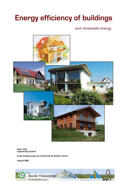
<strong>Energy</strong> <strong>efficiency</strong> <strong>of</strong> <strong>buildings</strong><br />
Alain Jolly,<br />
engineering student<br />
Ecole Polytechnique de l’Université de Nantes, France<br />
August 2006<br />
and renewable energy<br />
page 1
Index<br />
INTRODUCTION 5<br />
THE PASSIVE HOUSE CONCEPT 7<br />
SOLUTIONS THAT MAKE A BUILDING ENERGY-EFFICIENT 9<br />
I- HEATING AND COOLING 9<br />
1.1 INSULATION AND MINIMIZATION OF HEAT LOSSES 9<br />
1.2 OPTIMIZATION OF THE NATURAL GAINS 18<br />
II- HOUSEHOLD APPLIANCES 27<br />
2.1 WHITE GOODS 27<br />
2.2 BROWN GOODS 28<br />
2.3 OFFICE APPLIANCES 29<br />
2.4 LIGHTING 29<br />
REMAINING ENERGY NEEDS 33<br />
I. SPACE AND WATER HEATING 33<br />
1.1 SOLAR WATER HEATERS 33<br />
1.2 HEAT PUMPS 35<br />
1.3 BIOMASS (WOOD) HEATING 38<br />
II. ELECTRICITY 42<br />
2.1 SOLAR PHOTOVOLTAIC POWER 42<br />
2.2 WIND POWER 44<br />
CONCLUSION 47<br />
APPENDIX 1 51<br />
APPENDIX 2 53<br />
APPENDIX 3 55<br />
SOURCES 57<br />
page 3
Introduction<br />
Every time we switch on a light, a computer, the central heating, or even eat a<br />
hot meal we use energy. Everything we consume or use – our homes, their contents,<br />
our cars and the roads we travel on, the clothes we wear, and the food we eat –<br />
requires energy to produce and package, to distribute to shops or front doors, to<br />
operate, and then to get rid <strong>of</strong>. We rarely consider where this energy comes from or<br />
how much <strong>of</strong> it we use – or how much we truly need.<br />
Whether in the <strong>for</strong>m <strong>of</strong> gasoline to fuel a car or uranium to generate electricity,<br />
the energy required to support our economies and lifestyles provides tremendous<br />
convenience and benefits. But it also exacts enormous costs on human health,<br />
ecosystems, and even security. <strong>Energy</strong> consumption affects everything from a<br />
nation's <strong>for</strong>eign debt (due to fuel imports) to the stability <strong>of</strong> the Middle East. From the<br />
air we breathe to the water we drink, our energy use affects the health <strong>of</strong> current and<br />
future generations. Inefficient and unsustainable use <strong>of</strong> fossil fuels is altering the<br />
global climate by releasing carbon dioxide (CO2), which is one <strong>of</strong> the main gases that<br />
contribute to global warming, into the atmosphere. And as we seek out more-remote<br />
sources <strong>of</strong> fuel, we endanger the culture and way <strong>of</strong> life <strong>of</strong> indigenous peoples from<br />
the Amazon to the Arctic.<br />
Fossil fuels represented 88 % <strong>of</strong> the world energy demand in 2000. This is a<br />
real threat to today's climate. It doesn't just mean warmer summers and milder<br />
winters: global climate change is responsible <strong>for</strong> the increasing occurrence <strong>of</strong> floods,<br />
storms and droughts around the world. This would have a catastrophic effect on the<br />
Earth, with widespread melting <strong>of</strong> glaciers and ice-sheets, and a highly probable rise<br />
in sea level that could lead to the inundation <strong>of</strong> countries such as the Netherlands<br />
and Bangladesh. Latest scientific concern is focused on melting ice lowering salinity<br />
in the North Atlantic Ocean, which could lead to the reversal <strong>of</strong> the "Great Atlantic<br />
Conveyor" - better known as the Gulf Stream. If this were to happen we could<br />
witness temperatures in NW Europe falling by as much as 10°C, despite<br />
temperatures elsewhere in the world rising.<br />
The last report returned by the Intergovernmental Panel on Climate Change<br />
(IPCC) has confirmed that the average temperature <strong>of</strong> the Earth's atmosphere will<br />
rise from between 1,5 to 6°C by the end <strong>of</strong> the cent ury. The actual value will depend<br />
primarily on the importance and the date <strong>of</strong> application <strong>of</strong> the public policies<br />
implemented by the countries consuming the most energy.<br />
This warming has already caused climatic disturbances with extremely serious<br />
human repercussions <strong>of</strong> increasing importance to the future. To limit these dangers<br />
and ensure the sustainable development <strong>of</strong> our societies it is now acknowledged that<br />
it will be necessary to cut in half the world emissions <strong>of</strong> gases contributing to the<br />
greenhouse effect by 2050.<br />
Nuclear energy is the second world energy source with 7 % <strong>of</strong> the supply. The<br />
nuclear industry has presented itself as part <strong>of</strong> the solution to global warming<br />
because it does not emit any CO2. But nuclear power creates serious long-term<br />
security issues in the <strong>for</strong>m <strong>of</strong> risks <strong>of</strong> proliferation, severe nuclear accidents, and<br />
page 5
vulnerability to terrorism. Furthermore it produces radioactive waste at every stage <strong>of</strong><br />
the nuclear fuel cycle, from uranium mining and reactors to reprocessing irradiated<br />
nuclear fuel. Despite several decades <strong>of</strong> research, no nation has yet solved the<br />
problem <strong>of</strong> what to do with this material. Much <strong>of</strong> this nuclear waste will remain<br />
hazardous <strong>for</strong> thousands or even millions <strong>of</strong> years, leaving a poisonous legacy to<br />
future generations.<br />
Furthermore we must anticipate the future running out <strong>of</strong> fossil fuels, which are<br />
currently the main energy sources in the world. The global economy is highly<br />
dependent on these fuels that we consume faster and faster. This situation will lead<br />
us to a major crisis if we don't change our lifestyle and it is already responsible <strong>for</strong><br />
tensions and wars.<br />
Worldwide, people use about a third <strong>of</strong> all this energy in <strong>buildings</strong> – <strong>for</strong> heating,<br />
cooling, cooking, lighting and running appliances. It is one <strong>of</strong> the most important<br />
sectors, indeed the most important, <strong>for</strong> energy consumption in the industrialised<br />
countries. Building-related energy demand is rising rapidly, particularly within our<br />
homes. And potential savings in existing <strong>buildings</strong> are enormous. It has been shown<br />
in practice that in the developed countries energy consumption in existing <strong>buildings</strong><br />
can be reduced by a factor <strong>of</strong> 10! About new <strong>buildings</strong>, it has been shown that the<br />
consumption can be reduced by 75 % compared to the reference standards, at low<br />
extra cost! Improvements in the design and construction <strong>of</strong> <strong>buildings</strong> could yield<br />
significant energy savings. According to energy analyst Donald Aitken, "Buildings<br />
remain the most underrated aspect <strong>of</strong> energy economics, and the most unexploited<br />
opportunity <strong>for</strong> improving <strong>efficiency</strong>". It is particularly important to take account <strong>of</strong> this<br />
aspect because the cleanest energy is the one we don't use.<br />
Besides, considering the current and probably lasting increase <strong>of</strong> the energy<br />
cost, energy <strong>efficiency</strong> becomes also significantly important to save money.<br />
There<strong>for</strong>e, it is really necessary to reduce our energy consumption, especially at<br />
home and in the <strong>buildings</strong> where we work. However, energy <strong>efficiency</strong> does not<br />
require a compromise in occupant com<strong>for</strong>t, using higher <strong>efficiency</strong> makes it possible<br />
to increase com<strong>for</strong>t while reducing energy consumption.<br />
This document will first present the passive house concept, and then it will give<br />
in<strong>for</strong>mation about the different ways and solutions to make an energy-efficient<br />
building. These solutions are currently the most widely used because they are well<br />
known and easy to implement. Finally the last part is about the renewable energies<br />
we can use to fulfil the residual needs, such as electricity <strong>for</strong> appliances and heat.<br />
This report deals mainly with central-European <strong>buildings</strong>, that is to say that they need<br />
substantial heating in winter and moderate cooling in summer.<br />
page 6
The passive house concept<br />
Living in a house which has very low energy consumption and which is<br />
moreover environment-friendly and energy sufficient is not utopian, it is real. Passive<br />
houses are such houses. A passive house is a building in which a com<strong>for</strong>table<br />
interior climate can be maintained without active heating and cooling systems<br />
(Adamson 1987 and Feist 1988). The house heats and cools itself, hence "passive".<br />
The term "passive house" is now accepted as referring to a construction<br />
standard. For European passive construction prerequisite to this capability is an<br />
annual heating requirement that is less than 15 kWh/(m²a) (4755 Btu/ft²/yr), not to be<br />
attained at the cost <strong>of</strong> an increase in use <strong>of</strong> energy <strong>for</strong> other purposes (e.g.,<br />
electricity). Furthermore, the combined primary energy consumption <strong>of</strong> living area <strong>of</strong><br />
a European passive house may not exceed 120 kWh/(m²a) (38039 Btu/ft²/yr) <strong>for</strong><br />
heat, hot water and household electricity.<br />
Comparison <strong>of</strong> energy ratings <strong>of</strong> homes (Source: CEPHEUS)<br />
With this as a starting point, additional energy requirements may be completely<br />
covered using renewable energy sources.<br />
The passive house standard can be met using a variety <strong>of</strong> technologies, designs<br />
and materials. It is the result <strong>of</strong> the constant developments that have been made to<br />
the low-energy house concept: "Passive" building and technical measures ensure<br />
that very little heat is lost and that heat gains are optimally used, thus resulting in<br />
improvements to thermal com<strong>for</strong>t and a reduction in the energy requirements.<br />
page 7
The passive house provides us with the opportunity to reach extremely low<br />
levels <strong>of</strong> energy consumption by employing high-quality, cost-efficient measures to<br />
general building components - such measures are in turn an advantage to the<br />
ecology and economy sector. The energy consumption has been divided by 10 <strong>for</strong><br />
existing <strong>buildings</strong> converted into passive houses (Ludwigshafen AkkP 24 and<br />
Nuremberg Schulze Darup CEPHEUS demonstration projects).<br />
Most <strong>of</strong> the following solutions <strong>for</strong> building's energy <strong>efficiency</strong> are inspired by<br />
those which are used in passive houses.<br />
Passive house in Törwang, Germany (Source: Lechner Holzbau)<br />
page 8
Solutions that make a building<br />
energy-efficient<br />
The energy consumption <strong>of</strong> the current average European home is about 280<br />
kWh/m² per year and is essentially due to heating (80 %), water heating (10 %) and<br />
household electricity (10 %). For an <strong>of</strong>fice building, we should besides consider<br />
cooling. Consequently, heating is the main field on which we must make an ef<strong>for</strong>t.<br />
That's why this part principally deals with the ways to reduce the heating energy<br />
consumption. However the household consumption is also treated whereas the<br />
remaining energy needs are considered in the next part.<br />
I- Heating and cooling<br />
The main principles that we must apply to maintain a feeling <strong>of</strong> wellbeing in a<br />
building are super insulation to minimize the influence from outside and optimization<br />
<strong>of</strong> the passive natural (mainly solar) heat gains. These principles are based on heat<br />
transfer properties and the energy balance. Read appendix 1 and 2 <strong>for</strong> a better<br />
comprehension <strong>of</strong> how the following solutions work.<br />
1.1 Insulation and minimization <strong>of</strong> heat losses<br />
In winter, the aim <strong>of</strong> insulation is to prevent heat from leaving rather than to<br />
prevent the cold from entering. Indeed, the walls <strong>of</strong> an un-insulated dwelling do not<br />
retain the heat which passes through without heating the space. In summer, the<br />
insulation prevents heat from entering. The principle <strong>of</strong> the insulation is to use<br />
materials which have a thermal conductivity as low as possible in order to create a<br />
barrier between outside and inside, between the heat and the cold.<br />
Calculations and practical experiments carried out in several projects<br />
demonstrated that in climates comparable to central Europe, emphasizing the<br />
insulation is more efficient than emphasizing active or passive solar energy use. Note<br />
that it is however recommended to combine both <strong>of</strong> these strategies.<br />
Thermal wellbeing is not only depending on the air temperature, but also on wall<br />
temperature, the air circulation and on personal factors. The wellbeing decreases<br />
when a difference <strong>of</strong> more than 2°C exists between t he walls and the ambient air.<br />
The larger the difference in temperature between the walls and the ceiling <strong>of</strong> a room,<br />
the more discom<strong>for</strong>t we feel, due to the "cold radiation" <strong>of</strong> the walls. There<strong>for</strong>e, a<br />
heated room at 19°C but with the walls at 15°C will be more com<strong>for</strong>table than a room<br />
at 22°C but with the walls at 12°C. Thus insulation has to be designed to minimize<br />
the heat flux but it has also to keep the inside wall at a suitable temperature.<br />
page 9
1.1.1 An insulated shell<br />
The first rule to apply <strong>for</strong> the implementation <strong>of</strong> the insulation is that the whole<br />
exterior shell <strong>of</strong> the building must be insulated. Only one non-insulated part can lead<br />
to heavy heat losses.<br />
Many efficient insulation materials are now available such as cellulose, mineral<br />
wool, fibreglass, polystyrene, containing more or less recycled material, or cotton,<br />
sheep's wool, straw, hemp, which are natural materials. Other solutions exist; using<br />
cavity bricks or by leaving a layer <strong>of</strong> air between exterior and interior walls to act as<br />
insulation.<br />
With regard to another significant parameter <strong>for</strong> the insulation <strong>of</strong> the envelope,<br />
the glazed fenestration, very efficient materials are available <strong>for</strong> the glazing as well<br />
as the frames. This point will be dealt with in a special section about glazings.<br />
1.1.2 The thermal bridges<br />
One <strong>of</strong> the weak points <strong>of</strong> the heat insulation is the "thermal bridge". A thermal<br />
bridge is a portion <strong>of</strong> a structure whose high thermal conductivity lowers the overall<br />
thermal insulation <strong>of</strong> the structure. Indeed heat will flow the easiest path from the<br />
heated space to the outside - the path with the least resistance. This significantly<br />
increases heat loss. Due to the increased heat transfer across the thermal bridge, the<br />
surfaces on the warm side <strong>of</strong> the bridge (the internal side in winter) become cooler<br />
and vice versa, reducing<br />
the occupants' wellbeing. In<br />
the worst cases this can<br />
result in high humidity in<br />
parts <strong>of</strong> the construction.<br />
The main thermal bridges<br />
are caused by the<br />
presence <strong>of</strong> a conductive<br />
material crossing the<br />
insulation (metal framework<br />
in concrete or metal frame<br />
<strong>of</strong> a window) or by the<br />
walls' geometry (when the<br />
interior surface is smaller<br />
than the corresponding<br />
exterior surface, so more<br />
heat is transferred than in<br />
Location <strong>of</strong> the main thermal bridges (source: Passivhaus Institut)<br />
other areas). Examples<br />
are:<br />
• the lintel above a window<br />
• aluminium framing around a window<br />
• concrete or steel beams linking inside to outside temperatures<br />
• filling <strong>of</strong> air cavity with rubble<br />
• corners and junctions <strong>of</strong> walls and floors<br />
page 10
junction <strong>of</strong> a wall with an<br />
inside partition<br />
corners<br />
Examples <strong>of</strong> thermal bridges<br />
window<br />
There are different kinds <strong>of</strong> thermal bridges which depend on the kind <strong>of</strong><br />
insulation (internal, external or cavity brick wall). The better way to avoid thermal<br />
bridges is generally with external insulation, but this solution is not always feasible<br />
and is not enough to get rid <strong>of</strong> all the thermal bridges. Several techniques exist<br />
appropriate to each case. It is important to consider this aspect when designing a<br />
new building or renovating an old one.<br />
With regard to the windows and the doors, it is necessary to avoid metallic<br />
frames. They should have an insulated wooden or plastic frame to eliminate the<br />
thermal bridges.<br />
page 11
This simulation shows the typical thermal bridges in yellow : corners, windows and window lintels.<br />
The left-hand diagram shows the high heat flow caused by the lintel, the frame <strong>of</strong> the window and the single<br />
glazing. On the right-hand simulation you can see the consequences in terms <strong>of</strong> temperature.<br />
page 12
1.1.3 Glazings<br />
The insulating envelope <strong>of</strong> a<br />
building includes the windows. It means<br />
that the glazings too have to minimize<br />
the heat transfers. Single glazings were<br />
the most common glazings at the<br />
beginning <strong>of</strong> the 1970's, their U-value<br />
was some 5.5 W/(m²K). The heat losses<br />
through 1 m² <strong>of</strong> a single glazing window<br />
were equivalent to 60 L <strong>of</strong> heating oil<br />
per year in Central European climate.<br />
Cross section <strong>of</strong> a thermal com<strong>for</strong>t window<br />
(source: Passivhaus Institut)<br />
U-Value<br />
A measure <strong>of</strong> air-to-air heat transmission<br />
(loss or gain) due to thermal conductance<br />
and the difference in indoor and outdoor<br />
temperatures. As the U-Value decreases,<br />
so does the amount <strong>of</strong> heat that is<br />
transferred through the glazing material.<br />
The lower the U-Value, the more restrictive<br />
the wall (or the fenestration product) is to<br />
heat transfer (Reciprocal <strong>of</strong> the R-Value).<br />
The per<strong>for</strong>mance <strong>of</strong> the double<br />
glazings is much better (the heat loss<br />
coefficient is reduced to some 2.8<br />
W/(m²K)). There is an air gap enclosed<br />
between two panes, allowing almost half<br />
<strong>of</strong> the losses to be saved compared to<br />
single glazing. The interior surface<br />
temperature will not be lower than 7.5 °C<br />
even during extraordinary cold periods (-<br />
15°C). There will not be any frost pattern<br />
– but the surface is still uncom<strong>for</strong>tably<br />
cold and will show condensation, because<br />
the temperature is far lower than the dew<br />
point. The introduction <strong>of</strong> razor-thin metal<br />
coatings inside the inter-pane space is the<br />
most important success - called "low-e"layer<br />
<strong>for</strong> the low thermal emissivity. These<br />
coatings reduce the thermal radiation<br />
between the inner and the outer pane by<br />
a factor <strong>of</strong> 5 to 20. Even more, the gas in<br />
the gap is changed from air to noble<br />
gasses (Argon or Krypton), which have a<br />
far lower heat conductivity. A commonly<br />
used wooden or plastics window using a<br />
standard spacer and a standard double<br />
pane low-e glazing has a U–value<br />
between 1.3 and 1.7 W/(m²K), this is<br />
another reduction in heat loss by a factor <strong>of</strong> two when compared to the old double<br />
pane window. Now the average interior surface temperature will be some 13°C<br />
during heavy frost periods.<br />
The breakthrough <strong>for</strong> energy efficient construction is the availability <strong>of</strong> triplepane<br />
low-e glazing. If one adds two gaps between panes with one low-e-coating in<br />
page 13
A thermal com<strong>for</strong>t window with an Uw-value<br />
lower than 0.8 W/(m²K) assures a high<br />
thermal com<strong>for</strong>t.<br />
each gap and noble gas filling U-values<br />
between 0.5 and 0.8 W/(m²K) result. This<br />
requires that not only the glazing, but the whole<br />
window should have such a quality, including an<br />
insulating window frame and insulating spacers.<br />
The result is a "thermal com<strong>for</strong>t window". Using<br />
such a window the annual heat loss is reduced<br />
to no more than 8 L heating oil by each square<br />
meter <strong>of</strong> window area – this is a factor <strong>of</strong> eight<br />
compared to the initial value. But the<br />
advantages <strong>of</strong> the thermal com<strong>for</strong>t window are<br />
not only reduced heat loss, but also increased<br />
thermal com<strong>for</strong>t. Even during heavy frost<br />
periods the interior surface temperature will not<br />
fall below 17°C. The consequence is that no<br />
"cold radiation" can be perceived from such a<br />
window nor is an uncom<strong>for</strong>table cold air layer<br />
possible.<br />
Different models <strong>of</strong> thermal com<strong>for</strong>t windows (source: Passivhaus Institut)<br />
page 14
1.1.4 Airtightness<br />
The external envelope <strong>of</strong> a building should be as airtight as possible - this is true<br />
<strong>for</strong> conventional as well as <strong>for</strong> energy saving houses. It is the only means to avoid<br />
damage caused by condensation <strong>of</strong> moist, room temperature air penetrating the<br />
construction (see the figure on the right hand side). Such damage not only occurs in<br />
cold climates; in hot and humid climates the problem can occur from airflows from the<br />
outside to the inside. The cause is the same in both cases: a leaky building envelope.<br />
Drafts in living spaces are not tolerated by occupants any more, there<strong>for</strong>e a very<br />
airtight construction is essential to fulfil modern thermal com<strong>for</strong>t expectations.<br />
Air tightness should not be mistaken <strong>for</strong> insulation. Both qualities are essential<br />
characteristics <strong>of</strong> a high quality building envelope, but in most cases both have to be<br />
achieved independently:<br />
• A well insulated construction is not necessarily airtight. Air can easily pass<br />
through insulation made from coconut, mineral or glass wool. These materials<br />
have excellent insulation properties, but are not airtight.<br />
• On the other hand an airtight construction is not necessarily well insulated:<br />
e.g. a single aluminium foil can achieve excellent air tightness, but has no<br />
relevant insulation properties.<br />
Air tightness is an important,<br />
but not the most important<br />
requirement <strong>for</strong> energy efficient<br />
<strong>buildings</strong> (contrary to the<br />
impression given by some<br />
popular publications).<br />
Furthermore, achieving air<br />
tightness should not be mistaken<br />
with the function <strong>of</strong> a "vapour<br />
barrier". The latter is a diffusion<br />
tight layer, <strong>for</strong> example an oiled<br />
paper is airtight but allows<br />
moisture vapour to pass through.<br />
Conventional room plastering<br />
(gypsum or lime plaster, cement<br />
plaster or rein<strong>for</strong>ced clay plaster)<br />
is sufficiently airtight, but allows<br />
vapour diffusion.<br />
(source: Passivhaus Institut)<br />
Infiltration can not guarantee good indoor air quality. Houses built in Germany<br />
after 1985, <strong>for</strong> example, are so airtight that infiltration alone is inadequate to assure<br />
acceptable indoor air quality. Yet, these houses are still at risk regarding moisture<br />
damage to the construction from moist room air exfiltration. A greater level <strong>of</strong> air<br />
tightness is needed and these houses must be considered as "untight", their n50-air<br />
leakage varies between 4 and 10 h -1 . The consequences are draft-discom<strong>for</strong>t and<br />
moisture damage to the construction. The construction is too leaky to avoid<br />
page 15
exfiltration caused damages - but too tight <strong>for</strong> sufficient infiltration to maintain room<br />
air quality.<br />
The new 2001 German building code ("EnEV" <strong>Energy</strong> Saving Standard) <strong>for</strong> the<br />
first time addresses the air tightness <strong>of</strong> new constructions. Without a ventilation<br />
system the n50-airchange-values have to be less than 3 h -1 , with ventilation systems<br />
1.5 h -1 . From the experience in low energy houses, tighter construction (lower n50)<br />
leakages are recommended. In practice values between 0.2 und 0.6 h -1 have been<br />
measured in passive houses.<br />
Air tightness does not depend on a massive or light weight construction.<br />
Existing passive houses using masonry, timber, prefabricated, lost frame with<br />
concrete and steel bearing structure have achieved this superior level <strong>of</strong> air<br />
tightness. Sören Peper, a scientist at the Passive House Institute, has proved with a<br />
systematic field study that n50 leakage rates between 0.2 and 0.6 h -1 can reproducibly<br />
be achieved today. Careful design and accurate workmanship are the prerequisites<br />
to success. Construction details needed to achieve tightness are available <strong>for</strong> all<br />
important joint and envelope penetration situations. For timber constructions in most<br />
cases wooden composite boards are used (taped at the joints), in masonry<br />
construction a continuous inside plastering is sufficient. It is important, that the<br />
airtight envelope is continuous, without interruptions. This must be designed <strong>for</strong>, with<br />
particular attention to joints.<br />
(source: Passivhauss Institut)<br />
A key principle is maintaining "an<br />
undisturbed, airtight envelope", which<br />
can be recognised by the "rule <strong>of</strong> the<br />
red line" (see the section on the right<br />
hand side). Of course details are<br />
important, but an envelope can be air<br />
tight only if it consists <strong>of</strong> a uni<strong>for</strong>m, in<br />
tact, airtight enclosure wrapping<br />
around the whole house volume. The<br />
first step is that each element <strong>of</strong> the<br />
envelope which is to achieve air<br />
tightness must be specified (e.g. the<br />
particle board or OSB in a ro<strong>of</strong><br />
construction). The second step is<br />
determining how the airtight layers <strong>of</strong><br />
elements will be connected to assure<br />
lasting air tightness.<br />
With such an airtight envelope it is necessary to use a ventilation system to<br />
regulate the room air humidity. This system can also permit to reduce the heat<br />
losses.<br />
page 16
1.1.5 Ventilation with heat recovery<br />
Excellent indoor air quality is indispensable, but this can only be achieved if<br />
stale air is exchanged with fresh outdoor air at regular intervals. Ventilation will work<br />
accurately only if polluted air is removed constantly out <strong>of</strong> kitchen, bathrooms, and all<br />
other rooms with significant air pollution. Fresh air has to be supplied to the living<br />
room, children’s room, sleeping rooms, and workrooms to substitute the removed air.<br />
The system will supply exactly as much fresh air as is needed <strong>for</strong> com<strong>for</strong>t and <strong>for</strong><br />
good indoor air quality; only outdoor air will be supplied – no re-circulated air. This<br />
will lead to a high level <strong>of</strong> indoor air quality.<br />
What has been discussed so far could be satisfied by using a simple exhaust fan<br />
ventilation system, where the air is supplied through direct vents in external walls.<br />
These vents allow fresh (cold) air to enter the room at the required rate; however, the<br />
heat losses caused by such a system are much too high.<br />
Thus the ventilation installation must be combined with an efficient heat<br />
recovery system, this allows evacuating polluted air while keeping the heat inside the<br />
building. Heat from the exhaust air is recovered and applied to the supply air by a<br />
heat exchanger, the air flows are not mixed in the process. State <strong>of</strong> the art ventilation<br />
systems may have heat recovery rates <strong>of</strong> 75% to more than 95%. Of course this only<br />
works with counter flow heat exchangers and very energy efficient ventilators (using<br />
so called EC-motors with extraordinarily high <strong>efficiency</strong>). With this technology the<br />
recovered heat is 8 to 15-times higher than the electricity needed.<br />
The scheme <strong>of</strong> a com<strong>for</strong>table ventilation system. Stale air (brown) is removed permanently from the rooms<br />
with the highest air pollution. Fresh air (green) is supplied to the living rooms. (Section from the Passive<br />
House estate at Hannover Kronsberg, design by Rasch & Grenz. Source: Passivhaus Institut)<br />
page 17
This is how a counter flow heat exchanger works: The warm air (red, extract air) flows through a channel<br />
and delivers heat to the plates. This air will leave the exchanger cooled (orange, then called exhaust air). On<br />
the opposite side <strong>of</strong> the exchanger plates the fresh air (blue) flows in separate channels. This air will absorb<br />
the heat and it will leave the exchanger with a higher temperature (but still unpolluted), then called supply air<br />
(green). The counter flow principle allows <strong>for</strong> almost 100% recovery <strong>of</strong> the temperature difference, if the<br />
exchanger is long enough. In practise, systems with 75% to 95% are available. (source: Passivhauss Institut)<br />
Notes :<br />
• This ventilation system with heat recovery is useless if the building's envelope<br />
is not well airtight.<br />
• In winter, in a well designed building, the temperature is supposed to be lower<br />
than outside. As a consequence instead <strong>of</strong> being heated the inlet air is cooled<br />
by the heat exchanger. This system helps to keep a com<strong>for</strong>table inside<br />
temperature throughout the year, in winter as well as in summer.<br />
• In North America it is common to have air based heating and cooling systems<br />
(that's why it is called "air conditioning"). But the systems used in America are<br />
almost all just recirculating indoor air at a very high rate (but the air is not<br />
"changed", it is just recirculated). The system discussed here is something<br />
very different; it only replaces the indoor air at a very low rate with external air<br />
to maintain a good indoor air quality, there is no recirculated air. The airflows<br />
are much lower, there is almost no noise and no draft at all. Well, the use <strong>of</strong><br />
such a system might be very similar to that which Americans are used to - but<br />
much more com<strong>for</strong>table.<br />
1.2 Optimization <strong>of</strong> the natural gains<br />
The second main rule to follow in order to improve the energy <strong>efficiency</strong> <strong>of</strong> a<br />
building is to facilitate the natural energy gains (or to avoid them if the aim is to keep<br />
the rooms cool). The building design must be appropriate to seasonal needs. In<br />
temperate zones this mainly means favouring winter com<strong>for</strong>t (without deteriorating<br />
summer com<strong>for</strong>t). Such a building uses solar energy available as light or heat so that<br />
it consumes the least energy possible <strong>for</strong> a similar com<strong>for</strong>t. It must take into account<br />
the location, the aspect and the room arrangement in order to achieve these<br />
following functions:<br />
• harness the solar radiation<br />
• store the energy<br />
• distribute the heat inside<br />
• regulate the heat<br />
• avoid losses due to wind<br />
page 18
Besides solar energy, some heat can be collected from the ground thanks to a<br />
ground heat exchanger.<br />
But these measures must not lead to overheating the building in summer. That<br />
is why solar gain limitations must also be allowed in the warm season. In addition, a<br />
passive cooling system such as a geothermal heat exchanger can be added.<br />
This part is divided in two sections: the first one about heating and the second<br />
one about cooling. But in temperate climate, both <strong>of</strong> these functions have to be<br />
combined to ensure winter and summer wellbeing.<br />
1.2.1 Winter heating<br />
Most <strong>of</strong> the heat needed in winter to <strong>of</strong>fset the remaining losses can be provided<br />
by the sun. Heating with solar energy is easy: just let the sun shine in through the<br />
windows. The natural properties <strong>of</strong> glass let sunlight through but trap long-wave heat<br />
radiation, keeping the house warm (the greenhouse effect). The challenge <strong>of</strong>ten is to<br />
properly size the south-facing glass to balance heat gain and heat loss properties<br />
without overheating.<br />
Passive solar heating requires careful application <strong>of</strong> two main design principles:<br />
orientation <strong>of</strong> the glazings and room layout. Other simple systems can be added such<br />
as a greenhouse and thermal masses. This part will also deal with the appreciable<br />
amount <strong>of</strong> heat which can be gained from the ground, thanks to a geothermal heat<br />
exchanger.<br />
Building's shape and orientation <strong>for</strong> collection and distribution<br />
The difference between a passive solar building and a conventional building is<br />
design. And the key is designing a passive solar building to best take advantage <strong>of</strong><br />
the local climate. Besides the considerations about heat loss that have been<br />
discussed in the first part, elements <strong>of</strong> design include window location and the<br />
building's shape.<br />
The first component <strong>of</strong> a passive solar heating system is the collector,<br />
consisting <strong>of</strong> glazings. But increasing the glass area can increase building energy<br />
loss, especially if simple pane windows are used and if they face north. Because the<br />
sun’s position in the sky changes throughout the day and from one season to<br />
another, window orientation has a strong bearing on solar heat gain. Solar radiation<br />
has to be trapped by the greenhouse action <strong>of</strong> correctly oriented (south facing)<br />
windows exposed to full sun. The south side <strong>of</strong> the home must be oriented to within<br />
30 degrees <strong>of</strong> due south to receive about 90 percent <strong>of</strong> the optimal winter solar heat<br />
gain. Compared to a southern orientation, the south-south-east or south-south-west<br />
reduces by 5% the solar contributions; and south-east and south-west decrease<br />
them by 15%. As <strong>for</strong> the west and east orientations, up to 45% <strong>of</strong> the solar<br />
contribution is lost. North facing glazings are not advisable because they don't<br />
page 19
contribute to the solar radiation trapping. Thus<br />
they just favour heat loss as they are less<br />
insulating than walls.<br />
The heat trapped by the greenhouse<br />
effect has to be diffused to the main rooms.<br />
This diffusion is easier by orienting the house<br />
with the long axis running east/west (and,<br />
especially in cold climate, if the house is<br />
densely built-up). In addition, the main rooms<br />
(living room, kitchen, <strong>of</strong>fices and rooms used in<br />
the day time, e.g. children bedrooms) must be<br />
located on the south side to take advantage <strong>of</strong><br />
the solar energy. The rooms that need less<br />
heating should preferably be located by the<br />
north side. Lastly, the least used rooms must<br />
be situated on the north side in order to create<br />
a buffer zone increasing the insulation effect <strong>for</strong><br />
the main rooms. The garage, the wash-house,<br />
the staircases, the corridors, etc are ideal<br />
buffer zones. To diffuse the heat a strictly<br />
passive design will use the three natural heat<br />
transfer modes – conduction, convection, and radiation – exclusively. Radiation is the<br />
most com<strong>for</strong>table way <strong>of</strong> heat diffusion, it is per<strong>for</strong>med by floors and walls, which can<br />
also be used to stock the heat.<br />
Example <strong>of</strong> rooms arrangement<br />
Example <strong>of</strong> rooms arrangement (source: ADEME)<br />
(source: National <strong>Renewable</strong> <strong>Energy</strong><br />
Laboratory)<br />
page 20
Thermal masses<br />
Thermal mass, or materials used to store heat, is an integral part <strong>of</strong> most<br />
passive solar design. Materials such as concrete, masonry or wallboard absorb heat<br />
provided by the sun during the day and slowly release it by radiation as temperatures<br />
drop. This dampens the effects <strong>of</strong> outside air temperature changes and moderates<br />
indoor temperatures. The thermal masses can be walls or floors made <strong>of</strong> appropriate<br />
materials. These materials have a high density (i.e. little trapped air) and a high heat<br />
capacity, that is to say that a lot <strong>of</strong> heat energy is required to change their<br />
temperature. For instance; concrete, sandstone, baked clay and compressed earth<br />
are good thermal masses. Water has also a very high thermal capacity but it is more<br />
complicated to use. The more massive the thermal mass is, the more heat it can<br />
store. Conversely, light materials are bad thermal masses, as well as insulating<br />
materials and AAC (autoclaved aerated concrete) blocks.<br />
The surfaces <strong>of</strong> these masonry floors and walls are typically a dark colour<br />
because dark colours usually absorb more heat than light colours.<br />
The amount <strong>of</strong> passive solar (sometimes called the passive solar fraction)<br />
depends on the area <strong>of</strong> glazing and the amount <strong>of</strong> thermal mass. The glazing area<br />
determines how much solar heat can be collected. And the amount <strong>of</strong> thermal mass<br />
determines how much <strong>of</strong> that heat can be stored. It is possible to undersize the<br />
thermal mass, which results in the house overheating. There is a diminishing return<br />
on over sizing thermal mass, but excess mass will not hurt the per<strong>for</strong>mance. The<br />
ideal ratio <strong>of</strong> thermal mass to glazing varies by climate.<br />
Another important thing to remember is that the thermal mass must be insulated<br />
from the outside temperature. If it's not the collected solar heat can drain away<br />
rapidly, especially when thermal mass is directly connected to the ground, or in<br />
contact with outside air whose temperature is lower than the desired temperature <strong>of</strong><br />
the mass.<br />
In winter avoid coverings such as carpet that inhibit thermal mass absorption<br />
and transfer.<br />
An example <strong>of</strong> solar collector : the conservatory (or sunspace)<br />
A conservatory is a habitable glazed<br />
room. It is a heat source <strong>for</strong> the building and<br />
also constitutes a pleasant and luminous<br />
place directly heated by the sun. In order to<br />
ensure as much com<strong>for</strong>table as possible<br />
while still providing heat to the rest <strong>of</strong> the<br />
home several criteria must be taken into<br />
account. Indeed, although it collects the heat<br />
in winter the conservatory has to remain a<br />
pleasant living place all the year and still not<br />
to be overheated in summer. Most<br />
A sunspace within a home in Minden,<br />
Nevada (source: Donald Aitken, NREL)<br />
page 21
homeowners and builders also separate the sunspace from the home with doors<br />
and/or windows so that home com<strong>for</strong>t isn’t overly affected by the sunspace’s<br />
temperature variations. The interface between the conservatory and the housing is<br />
important: at night it transmits to the rooms the heat collected during the day. It has<br />
to act as a thermal mass; the choice <strong>of</strong> materials is very important. It is also possible<br />
to transfer the heat to the ventilation system with heat recovery.<br />
Thus a conservatory has to:<br />
• collect the sun radiation in winter (it has to be sheltered from it in summer)<br />
• stock the heat<br />
• transfer efficiently the heat toward the housing<br />
Principle on which a conservatory works<br />
Orientation: The best orientation is facing South, but South-West and South-<br />
East are good too. Full West orientation is particularly bad because the sunshine<br />
comes frontally to the glazings in the afternoon, the hottest moment <strong>of</strong> the day,<br />
causing overheat.<br />
Colours: On inner walls dark and warm colours are better as they absorb the<br />
solar energy more efficiently. Brown, maroon and ochre are suitable colours. White<br />
has to be avoided because it is a reflective colour which would return the solar<br />
radiation outside.<br />
Shape: Conservatories can have various shapes, which have to fit the needs<br />
and possibilities in each case, as well as the climate (see below the main shapes).<br />
An opaque ro<strong>of</strong> is recommended in warm and sunny climates.<br />
page 22
Different positions and shapes <strong>for</strong> a conservatory (source: ADEME)<br />
For a multi-storeyed building it can be relevant to build a multi-storeyed or at<br />
least a high-ceilinged conservatory to facilitate the heating <strong>of</strong> the upper floors.<br />
However, this may need a careful design (in case <strong>of</strong> more than two levels) to avoid<br />
overheating the last floors.<br />
A different view <strong>of</strong> the same sunspace (source: Donald Aitken, NREL)<br />
page 23
In summer: A conservatory thermally well designed must be sheltered from the sun<br />
in summer. Openings are recommended in the high part as well as external blinds.<br />
Drawing heat from the ground with a ground heat exchanger<br />
An additional opportunity to collect natural heat is to use a simple system called<br />
ground (or geothermal) heat exchanger connected to the heat recovery ventilation<br />
system. The ground during winter has a higher temperature than outdoor air, and<br />
during the summer a lower temperature than outdoor air. The deeper you are the<br />
steadier the temperature (at 2 m depth the temperature is almost constant and<br />
around 10 to 18 °C according to the climate). There <strong>for</strong>e it is possible to preheat fresh<br />
air in an earth<br />
buried duct in<br />
winter, or to cool it<br />
in summer. This<br />
can be done<br />
directly with air<br />
ducts in the<br />
ground, or<br />
indirectly with brine<br />
circulating in earth<br />
buried pipes and<br />
heating or cooling<br />
the air with a<br />
water-to-air heat<br />
exchanger.<br />
The pipes<br />
Ground heat exchanger connected to the ventilation system with heat recovery<br />
generally used are<br />
less than 200 mm<br />
in diameter to facilitate the heat transfer and are made <strong>of</strong> polyethylene. The duct<br />
must be buried at least 1.20 m deep and it is not pr<strong>of</strong>itable to go beyond 1.80 m. The<br />
longer the covered distance is the closer one gets to the earth’s air temperature. It is<br />
recommended to be more than 50 m long to reach a good impact. Finally, the circuit<br />
has to be buried far enough from the building to avoid subtracting heat from the<br />
building.<br />
Wind protection<br />
When the wind blows on a building, it increases the convective heat transfer<br />
between it and the atmosphere. In Europe the wind is usually stronger in winter thus<br />
it is better to shield the houses from it and limit heat losses. Trees, fences, or<br />
geographical features can be used as windbreaks.<br />
Evergreen trees and shrubs planted to the prevailing wind direction (usually<br />
north and west) are the most common type <strong>of</strong> windbreak. Trees, bushes, and shrubs<br />
page 24
are <strong>of</strong>ten planted together to block or impede wind from ground level to the treetops.<br />
Or, evergreen trees combined with a wall, fence, or earth berm (natural or man-made<br />
walls or raised areas <strong>of</strong> soil) can deflect or lift the wind over the home. Be careful not<br />
to plant evergreens too close to your home’s south side as this would prevent the<br />
absorption <strong>of</strong> warmth from the winter sun.<br />
A windbreak will reduce wind speed <strong>for</strong> a distance <strong>of</strong> as much as 30 times the<br />
windbreak’s height. But <strong>for</strong> maximum protection, plant your windbreak at a distance<br />
from your home <strong>of</strong> two to five times the mature height <strong>of</strong> the trees.<br />
Properly selected and placed evergreen trees and<br />
shrubs can shelter the home from winter winds<br />
and reduce heating costs. (source: NREL)<br />
1.2.2 Summer "cooling"<br />
Overhangs<br />
Fixed protections on a high school in Cavaillon,<br />
France<br />
If south winds are a problem in the winter,<br />
plant evergreens far enough away to lift winds<br />
without shading the home. (source: NREL)<br />
It makes little sense to save energy on<br />
winter heating just to spend it on summer<br />
cooling. So in most climates, a good building<br />
design must provide summer com<strong>for</strong>t as<br />
well. Here the issue is not exactly to cool the<br />
building but to limit the natural heat gains.<br />
Insulation, air tightness and ventilation are<br />
as important as in winter to maintain the<br />
inner temperature. A geothermal heat<br />
exchanger can cool the in-going air during<br />
the summer while providing heat in winter.<br />
The main improvement which can be<br />
done is to shelter the south-facing glazings<br />
from the summer sun. The solar heat must<br />
be blocked by architectural masks, a ro<strong>of</strong><br />
overhang, slatted canopies or other<br />
devices such as awnings, shutters, and<br />
trellises. These outside protections are<br />
much more efficient than inside<br />
protections.<br />
The advantage <strong>of</strong> architectural<br />
masks, overhangs and slatted canopies is<br />
that they are totally passive (there is no<br />
page 25
need to put them on or <strong>of</strong>f). They have to be sized so that they allow the winter<br />
sunshine and avoid summer sunshine to reach the windows.<br />
Note: Architectural masks are parts <strong>of</strong> a building (balconies, loggias, etc) which<br />
create shadows on other parts <strong>of</strong> this building, usually glazings.<br />
The shadows created by these<br />
systems depend on several parameters:<br />
• the time<br />
• the season<br />
• the shape and the size <strong>of</strong> the<br />
glazing<br />
• the shape and the size <strong>of</strong> the mask<br />
or overhang<br />
• the position <strong>of</strong> the mask or<br />
overhang regard to the glazing<br />
Their length has to be calculated so<br />
that they allow winter sun and cut summer<br />
sun, this depends on the latitude, the<br />
orientation and the window size.<br />
Adjustable canopies allow the<br />
appropriate protection <strong>for</strong> the changing<br />
conditions (sun's height along the day and<br />
sunlight), outside Venetian blinds can be<br />
adjusted as well.<br />
Another solution is to use<br />
vegetation to provide shade <strong>for</strong> the<br />
building. To block solar heat in the<br />
summer but let much <strong>of</strong> it in during the<br />
winter, use deciduous trees. Deciduous<br />
trees with high, spreading crowns (i.e.,<br />
leaves and branches) can be planted to<br />
the south <strong>of</strong> your home to provide<br />
maximum summertime ro<strong>of</strong> and<br />
windows shading. Trees with crowns<br />
lower to the ground are more<br />
appropriate to the west, where shade is<br />
needed from lower afternoon sun<br />
angles.<br />
(source: NREL)<br />
Deciduous shading trees to the south and west and<br />
wind breaking evergreens to the prevailing winter<br />
winds direction. (Source: NREL)<br />
page 26
II- Household appliances<br />
Once a building is built following the principles mentioned up to now in the first<br />
parts, most <strong>of</strong> its energy consumption is due to the household appliances (fridge,<br />
lighting, dishwasher, TV, etc). Following an important series <strong>of</strong> measurements one<br />
could show that it is possible to reduce their consumption by 40% to 45% in housing.<br />
It corresponds to an energy saving in 1 200 to 1 800 kWh/an (Source Cabinet<br />
SIDLER).<br />
2.1 White goods<br />
Distribution <strong>of</strong> the Household goods energy consumption (Source: ADEME)<br />
First <strong>of</strong> all these devices have to be chosen according to the needs. A big<br />
appliance consumes more than a small one. Thus it is important to adjust the size to<br />
the family's needs.<br />
1 person 100 to 150 L<br />
2 or 3 persons 150 to 250 L<br />
3 or 4 persons 250 to 350 L<br />
More than 4 persons 350 to 500 L<br />
Fridge size<br />
Be aware that a US fridge consumes 3 times as much as a normal one.<br />
Most <strong>of</strong> the energy consumed by a washing machine or a dishwasher is used to<br />
heat the water via an electrical element. It is better to connect the machine to hot<br />
water heated via renewable energy (see next chapter, Remaining energy needs).<br />
page 27
Average energy consumption according to appliances<br />
(Source: Enertech 2002)<br />
A recent device consumes much less<br />
electricity than an old one but different appliances<br />
from the same generation can have very different<br />
efficiencies. According to an EU Directive most<br />
white goods and light bulb packaging must have an<br />
EU <strong>Energy</strong> Label clearly displayed when <strong>of</strong>fered<br />
<strong>for</strong> sale or rent. The energy <strong>efficiency</strong> <strong>of</strong> the<br />
appliance is rated in terms <strong>of</strong> a set <strong>of</strong> energy<br />
<strong>efficiency</strong> classes from A to G on the label, A being<br />
the most energy efficient, G the least efficient. The<br />
most efficient fridges and freezers can now be<br />
identified by new ‘A+’ and ‘A++’ markings on the<br />
Example EU energy label<br />
large black arrow appearing against the green ‘A’ arrow. By law, this label must be<br />
displayed on all new household products <strong>of</strong> the following types:<br />
• Refrigerators, freezers and fridge-freezer combinations<br />
• Washing machines<br />
• Electric tumble dryers<br />
• Combined washer-dryers<br />
• Dishwashers<br />
• Lamps<br />
• Electric ovens<br />
• Air conditioners<br />
2.2 Brown goods<br />
It is more difficult to know the <strong>efficiency</strong> <strong>of</strong> audiovisual equipment because they<br />
don't have any energy label. However it is possible in most cases to reduce their<br />
consumption quite easily. Usually these appliances are not turned <strong>of</strong>f but only put on<br />
standby. This consumes useless electricity. If care is not taken the TV, the video tape<br />
page 28
ecorder, the DVD player, the hi-fi system, the TV decoder, the amplifier, etc, remain<br />
on standby mode permanently and finally consume more "<strong>of</strong>f" than on. For instance,<br />
a video tape recorder (which is rarely used) uses more than 90 % <strong>of</strong> its annual<br />
electric consumption when it does not run! A well-equipped family can consume<br />
anywhere from 100 kWh to more than 800 kWh per year only <strong>for</strong> appliances on<br />
standby mode! Thus it is recommended to turn them <strong>of</strong>f.<br />
2.3 Office appliances<br />
Office computing (computers, peripherals, printers, modems, phones, fax, etc)<br />
has a smaller consumption than white goods. Nevertheless the use <strong>of</strong> these devices<br />
is increasing so that their share in the total energy consumption increases. These<br />
appliances are also generally left on standby mode.<br />
It is recommended to use <strong>Energy</strong> Star labelled appliances. The<br />
<strong>Energy</strong> Star label indicates that the device is energy efficient in use<br />
as well as on standby. The <strong>Energy</strong> Star data base (www.euenergystar.org)<br />
allows you to find the most powerful models in terms<br />
<strong>of</strong> energy <strong>efficiency</strong>.<br />
Advice:<br />
• Laptops consume 50 to 80 % less energy than desktops<br />
• Flat liquid crystal screens consume 60 % less energy than an ordinary screen<br />
• Ink jet printers consume 5 to 10 W in use and don't need pre-heating as do<br />
laser printers (200 to 300 W)<br />
• Combined appliances (<strong>for</strong> instance printer + scanner) consume less energy<br />
than the appliances themselves together.<br />
2.4 Lighting<br />
2.4.1 Natural light<br />
The most ecological light comes from the sun. Although it is only available at<br />
daytime, it is better to use it as much as possible thanks to a well thought out home<br />
arrangement and light ducts.<br />
Home arrangement advice:<br />
• Use light colours inside, especially <strong>for</strong> ceilings, as they reflect the light.<br />
• Place the furniture so that it avoids shade on tables and desks.<br />
• Place the work-tops in front <strong>of</strong> windows.<br />
Light ducts:<br />
In a building designed <strong>for</strong> passive solar heating, the rooms located to the north<br />
receive much less natural light because most <strong>of</strong> the glazings are south-facing.<br />
However, it is possible to lead the sunlight to these rooms via light ducts.<br />
page 29
The light duct is a simple system which allows the flow <strong>of</strong> sunlight into a dark<br />
place thanks to a reflective film covering its inner wall. A breakthrough in this<br />
technology is a new film with a reflective factor <strong>of</strong> 99 %. The system includes a dome<br />
(sunlight collector) located on the ro<strong>of</strong>, the duct itself consisting in a rigid pipe <strong>of</strong> 250<br />
to 650 mm in diameter according to the geographic location and the amount <strong>of</strong> light<br />
needed, and a diffuser located in the room to be lighted.<br />
Principle <strong>of</strong> the light duct<br />
(Source: ADEME)<br />
2.4.2 Artificial light<br />
In Europe, electric lighting can<br />
account <strong>for</strong> 400 to 600 kWh/year in<br />
housing. This consumption can<br />
easily be divided in two, particularly<br />
using energy efficient lamps. There<br />
are two main kinds <strong>of</strong> lamps<br />
available: incandescent lamps<br />
(including ordinary bulbs and<br />
halogens) and fluorescent lamps<br />
(including tubes and energy saving<br />
bulbs). Besides, another kind <strong>of</strong><br />
lamp, using LEDs, is appearing.<br />
Let's first consider the two<br />
main categories:<br />
Incandescent bulbs consist <strong>of</strong><br />
two electrodes with a tungsten<br />
filament attached between them.<br />
When the light is switched on<br />
Components <strong>of</strong> a light duct (Source: ADEME)<br />
Lamps comparison (Source: S. Bedel and T. Salomon, La<br />
maison des négawatts, Edition Terre Vivante)<br />
page 30
electricity flows through and heats up the filament until it glows, they produce a lot <strong>of</strong><br />
heat (95 % <strong>of</strong> their energy consumption) and little light (5 %). In a fluorescent lamp, a<br />
gas is encased within a glass tube coated with a layer <strong>of</strong> phosphor. When electricity<br />
passes through the gas it emits ultraviolet rays which cause the phosphor coating to<br />
glow, this is more energy efficient because most <strong>of</strong> the energy is turned into light (80<br />
%) instead <strong>of</strong> heat (20 %). Among these lamps energy saving bulbs are particularly<br />
interesting because they are compact and their caps are similar to the ordinary ones'.<br />
For the same amount <strong>of</strong> light a 18 W energy saving bulb consumes 5 times less<br />
energy than a 100 W ordinary bulb and lasts 10 times as long (10 000 hours). While<br />
energy saving bulbs cost more initially the electricity that they save easily recovers<br />
this cost over their life span.<br />
As <strong>for</strong> white goods, the energy label is compulsory <strong>for</strong> domestic light bulbs.<br />
Classes A and B<br />
Class D<br />
Classes E and F<br />
LED lamps<br />
<strong>Energy</strong> savers fall in to these<br />
categories. They are the most<br />
efficient type <strong>of</strong> light bulb and<br />
use up to 80% less energy than<br />
standard light bulbs.<br />
Mains voltage halogen bulbs<br />
usually fall into this category.<br />
Standard incandescent light<br />
bulbs are the least efficient<br />
alternatives.<br />
Nowadays a new kind <strong>of</strong> energy saving lamp is<br />
appearing: LED (light-emitting diode) lamps. Already used<br />
<strong>for</strong> a long time <strong>for</strong> traffic lights and electronics panels they<br />
are moving to home lighting with their new white colour.<br />
They are composed <strong>of</strong> several super-bright LED with a very<br />
high life span (100 times as long as an ordinary bulb, i.e. 50<br />
000 to 100 000 hours!). In addition there is no glass or<br />
filament which makes LED lamps particularly durable. Their<br />
main drawback is that they are still too expansive.<br />
page 31
Remaining energy needs<br />
Despite the huge amount <strong>of</strong> energy which is possible to save in a building<br />
thanks to all the previously mentioned measures, energy is still necessary <strong>for</strong><br />
different uses. It is needed <strong>for</strong> heating domestic water, <strong>for</strong> back-up heating, <strong>for</strong> light<br />
and electric appliances. In order to limit the building's impact on the environment it is<br />
preferable to use renewable energy with this aim in view.<br />
I. Space and water heating<br />
Hot water is needed both <strong>for</strong> space heating and <strong>for</strong> domestic use (shower, cooking, etc). It can<br />
be provided by a solar water heater, by a heat pump, by geothermal energy, by a boiler using<br />
biomass as a fuel or by an electric heater (see next part, Electricity).<br />
1.1 Solar water heaters<br />
Solar hot water heaters use the sun to heat either water or a heat-transfer fluid<br />
in collectors. There are passive systems (based on the thermo-siphon principle, the<br />
water flows upward when heated in the panel) and active systems (using a pump to<br />
circulate the fluid). Sometimes the plumbing from a solar heater connects to a<br />
house's existing water heater, which stays inactive as long as the water coming in is<br />
hot or hotter than the temperature setting on the indoor water heater. When it falls<br />
below this temperature the home's water heater can kick in to make up the<br />
difference.<br />
Most systems use a ro<strong>of</strong>-mounted solar collector, so you’ll need a south-facing<br />
ro<strong>of</strong> with good solar exposure.<br />
The most common collector <strong>for</strong> solar hot water is the flat plate collector. It is a<br />
rectangular box with a transparent cover (to raise the temperature by greenhouse<br />
effect). Small tubes run through the box and carry fluid, either water or other fluid,<br />
such as an antifreeze solution. The tubes attach to a black absorber plate, as heat<br />
builds up in the collector it heats the fluid passing through the tubes. The hot water or<br />
liquid goes to a storage tank. If the fluid is not hot water, water is heated by passing it<br />
through a tube inside the storage tank full <strong>of</strong> hot fluid.<br />
Evacuated tube collectors consist <strong>of</strong> rows <strong>of</strong> parallel transparent glass tubes, each<br />
containing an absorber and covered with a selective coating. Sunlight enters the<br />
tube, strikes the absorber and heats the liquid flowing through the absorber. These<br />
collectors are manufactured with a vacuum between the tubes, which helps them<br />
achieve extremely high temperatures (80 to 180°C, s o they are appropriate <strong>for</strong><br />
commercial and industrial uses).<br />
page 33
Evacuated tube collectors Flat plate collectors<br />
Direct systems use a pump to circulate potable water from the water storage<br />
tank through one or more collectors and back into the tank. In indirect systems, a<br />
heat exchanger heats a fluid that circulates in tubes through the water storage tank,<br />
transferring the heat from the fluid to the potable water.<br />
Solar water heaters allow savings up to 70 % <strong>of</strong> the energy needed to heat<br />
water. A typical system <strong>for</strong> a four-person home in a sunny region consists <strong>of</strong> a tank <strong>of</strong><br />
150 to 300 L and 3 to 4 m² <strong>of</strong> solar collector panels.<br />
Solar water heater (active system) with back-up heater (Source: ADEME)<br />
page 34
1.2 Heat pumps<br />
Heat flows naturally from a higher to a lower temperature. Heat pumps,<br />
however, are able to <strong>for</strong>ce the heat flow in the other direction. Although we may not<br />
know it, heat pumps are very familiar to us - fridges and air conditioners are two<br />
examples. A heat pump is a machine which moves heat from a low temperature<br />
reservoir to a higher temperature reservoir under supply <strong>of</strong> work (see appendix 3).<br />
Even at temperatures we consider to be cold, air, ground and water contain useful<br />
heat that's continuously replenished by the sun (thus they are renewable energy<br />
sources). Heat pumps can transfer heat from these natural heat sources in the<br />
surroundings to a building. Heat pumps can also be used <strong>for</strong> cooling; heat is then<br />
transferred in the opposite direction, from the application that is cooled to<br />
surroundings at a higher temperature. Sometimes the excess heat from cooling is<br />
used to meet a simultaneous heat demand.<br />
1.2.1 The vapour compression heat pump<br />
The great majority <strong>of</strong> heat pumps work on the principle <strong>of</strong> the vapour<br />
compression cycle. The main components in such a heat pump system are:<br />
• the evaporator - (e.g. the squiggly thing in the cold part <strong>of</strong> your fridge) takes<br />
the heat from the heat source;<br />
• the compressor - (this is what makes the noise in a fridge) moves the<br />
refrigerant round the heat pump and compresses the gaseous refrigerant to<br />
the temperature needed <strong>for</strong> the heat distribution circuit;<br />
• the condenser - (the hot part at the back <strong>of</strong> your fridge) gives up heat to a hot<br />
water tank which feeds the distribution system.<br />
• the expansion valve expands the high-pressure working fluid to the evaporator<br />
pressure and temperature.<br />
These components are connected to <strong>for</strong>m<br />
a closed circuit, as shown in the figure righthand.<br />
A volatile liquid, known as the working<br />
fluid or refrigerant, circulates through the four<br />
components. In the evaporator the<br />
temperature <strong>of</strong> the liquid working fluid is kept<br />
lower than the temperature <strong>of</strong> the heat source,<br />
causing heat to flow from the heat source to<br />
the liquid, and the working fluid evaporates.<br />
Vapour from the evaporator is compressed to<br />
a higher pressure and temperature. The hot<br />
vapour then enters the condenser, where it<br />
condenses and gives <strong>of</strong>f useful heat. Finally,<br />
the high-pressure working fluid is expanded to<br />
the evaporator pressure and temperature in<br />
The vapour compression heat pump<br />
(Source: Heat Pump Center, IEA)<br />
the expansion valve. The working fluid is returned to its original state and once again<br />
enters the evaporator. The compressor is usually driven by an electric motor.<br />
page 35
The evaporator can easily be turned into a condenser and vice versa, so that<br />
the heat pump works in the other way. The hot side and the cold side are then<br />
switched around by use <strong>of</strong> a reversing valve which switches the direction <strong>of</strong><br />
refrigerant through the cycle.<br />
1.2.2 The absorption heat pump<br />
The other kind <strong>of</strong> heat pump is the absorption heat pump. Although mainly used<br />
in industrial or commercial settings, absorption coolers are now commercially<br />
available <strong>for</strong> large residential homes, and absorption heaters are under development.<br />
Absorption heat pumps are thermally driven, which means that heat rather than<br />
mechanical energy is supplied to drive the cycle. This system utilises the ability <strong>of</strong><br />
liquids or salts to absorb the vapour <strong>of</strong> the working fluid. The most common working<br />
pairs <strong>for</strong> absorption systems are:<br />
• water (working fluid) and lithium bromide (absorbent); and<br />
• ammonia (working fluid) and water (absorbent).<br />
Residential absorption heat pumps use<br />
an ammonia-water absorption cycle to<br />
provide heating and cooling. As in a<br />
standard heat pump the refrigerant (in this<br />
case, ammonia) is condensed in one coil to<br />
release its heat; its pressure is then reduced<br />
and the refrigerant is evaporated to absorb<br />
heat. If the system absorbs heat from the<br />
interior <strong>of</strong> your home, it provides cooling; if it<br />
releases heat to the interior <strong>of</strong> your home, it<br />
provides heating. But absorption heat<br />
pumps are not reversible as the vapour<br />
compression heat pumps are.<br />
The absorption heat pump (Source: Heat<br />
Pump Center, IEA)<br />
The difference in absorption heat<br />
pumps is that the evaporated ammonia is not pumped up in pressure in a<br />
compressor, but is instead absorbed into water. A relatively low-power pump can<br />
then pump the solution up to a higher pressure. The problem then is removing the<br />
ammonia from the water, and that's where the heat source comes in. The heat<br />
essentially boils the ammonia out <strong>of</strong> the water, starting the cycle again.<br />
The advantage <strong>of</strong> absorption systems is that they can make use <strong>of</strong> any heat<br />
source, because <strong>of</strong> this they can make use <strong>of</strong> solar energy, geothermal hot water, or<br />
other heat sources.<br />
page 36
1.2.3 The heat sources<br />
In cooling use the heat source is <strong>of</strong> course the inside <strong>of</strong> the building. In heating<br />
mode, the main heat sources used are ambient air, ground water and ground (they<br />
are heat sinks when operating in cooling mode).<br />
• Ambient air is free and widely available, and it is the most common heat<br />
source <strong>for</strong> heat pumps. Air-source heat pumps, however, achieve on average<br />
10-30% lower seasonal per<strong>for</strong>mance factor (SPF) than water-source heat<br />
pumps. This is mainly due to the rapid fall in capacity and per<strong>for</strong>mance with<br />
decreasing outdoor temperature, the relatively high temperature difference in<br />
the evaporator and the energy needed <strong>for</strong> defrosting the evaporator and to<br />
operate the fans.<br />
• Ground water is available with stable temperatures (4-10°C) in many regions.<br />
Open or closed systems are used to tap into this heat source. In open systems<br />
the ground water is pumped up, cooled and then re-injected in a separate well<br />
or returned to surface water. A major disadvantage <strong>of</strong> ground water heat<br />
pumps is the cost <strong>of</strong> installing the heat source. Additionally, local regulations<br />
may impose severe constraints regarding interference with the water table and<br />
the possibility <strong>of</strong> soil pollution.<br />
• Ground-source systems are used <strong>for</strong> residential and commercial<br />
applications and have similar advantages as (ground) water-source systems,<br />
i.e. they have relatively high annual temperatures. Heat is extracted from<br />
pipes laid horizontally or vertically in the soil (horizontal/vertical ground coils).<br />
The thermal capacity <strong>of</strong> the soil varies with the moisture content and the<br />
climatic conditions. Due to the extraction <strong>of</strong> heat from the soil, the soil<br />
temperature will fall during the heating season. In cold regions most <strong>of</strong> the<br />
energy is extracted as latent heat when the soil freezes. However, in summer<br />
the sun will raise the ground temperature, and complete temperature recovery<br />
may be possible.<br />
Higher efficiencies are achieved<br />
with geothermal (ground-source or<br />
water-source) heat pumps, they can<br />
be used in more extreme climatic<br />
conditions than air-source heat pumps,<br />
and customer satisfaction with the<br />
systems is very high. The ground is<br />
nowadays the most used source <strong>for</strong><br />
residential application. There are four<br />
basic types <strong>of</strong> closed ground loop<br />
systems: vertical, horizontal (1 to 2 m<br />
deep), slinky and pond/lake. Which<br />
one <strong>of</strong> these is best depends on the<br />
climate, soil conditions, available land,<br />
and local installation costs at the site.<br />
page 37
All <strong>of</strong> these approaches can be used <strong>for</strong> residential and commercial building<br />
applications.<br />
1.3 Biomass (wood) heating<br />
Residential vapour compression ground heat pump<br />
Biomass is a renewable energy resource provided by plants and animals. It<br />
includes the carbonaceous waste <strong>of</strong> various human and natural activities. It is<br />
derived from numerous sources, including the by-products from the timber industry,<br />
agricultural crops, raw material from the <strong>for</strong>est, major parts <strong>of</strong> household waste and<br />
wood.<br />
Biomass does not add carbon dioxide to the atmosphere as it absorbs the same<br />
amount <strong>of</strong> carbon in growing as it releases when consumed as a fuel. Even allowing<br />
<strong>for</strong> emissions <strong>of</strong> fossil carbon dioxide in planting, harvesting, processing and<br />
transporting the fuel, replacing fossil fuel with wood fuel will typically reduce net CO2<br />
emissions by over 90%.<br />
Wood is the most used biomass fuel <strong>for</strong> space heating; it has been used <strong>for</strong><br />
millenniums. Nowadays it is a very versatile fuel and can be burned in many different<br />
<strong>for</strong>ms and in a number <strong>of</strong> different appliances. It can be burned to heat one or more<br />
rooms, the whole house, to produce hot water and to cook on or a combination <strong>of</strong> all<br />
or some <strong>of</strong> these. Today you can choose from a new generation <strong>of</strong> wood burning<br />
appliances that are cleaner burning, more efficient, and powerful enough to heat<br />
modern homes and even supply district heating. At present domestic heating with<br />
wood is the most efficient and most competitive way <strong>of</strong> using biomass <strong>for</strong> energy.<br />
Several different technical concepts are available <strong>for</strong> domestic heating, including<br />
masonry heaters, stoves and boilers. Improvements in building insulation are leading<br />
to significant reductions in fuel demand. This reduces the handling ef<strong>for</strong>t and the<br />
page 38
equired storage space <strong>for</strong> wood fuels - which used to be major disadvantages <strong>of</strong><br />
heating with wood.<br />
1.3.1 Masonry heaters<br />
An ordinary fireplace is more a decorative object than a heating appliance. To<br />
produce heat <strong>for</strong> one or more rooms logs can be burned on an open fire, these look<br />
nice but tend to have low efficiencies - about 80-85% <strong>of</strong> the heat that goes up the<br />
chimney. On the other hand masonry heaters, also known as "Russian," "Siberian,"<br />
and "Finnish" fireplaces, commonly reach a combustion <strong>efficiency</strong> <strong>of</strong> 90%. They take<br />
advantage <strong>of</strong> a big thermal mass to absorb and later release the heat from the fire.<br />
Masonry heaters include a firebox, a large masonry mass (such as bricks or<br />
stones), and long twisting smoke channels that run through the masonry mass. Their<br />
fireboxes are lined with firebrick, refractory concrete, or similar materials that can<br />
handle temperatures over 1,000°C.<br />
Example masonry heater<br />
1.3.2 Wood boilers<br />
A small hot fire built once or twice a<br />
day releases heated gases into the long<br />
masonry heat tunnels. The masonry absorbs<br />
the heat and then slowly releases it into the<br />
house over a period <strong>of</strong> 12–20 hours. A wide<br />
variety <strong>of</strong> masonry heater designs and styles<br />
are available. Larger models resemble<br />
conventional fireplaces and may cover an<br />
entire wall. Smaller models take up about as<br />
much space as a wood or pellet stove. They<br />
cost from 5,000 to 15 000 € but avoid a<br />
central heating system investment provided<br />
the house is built following the previous<br />
recommendations in first part.<br />
The development from the multi-fuel boiler <strong>of</strong> the past to today's modern<br />
logwood boilers represents a quantum leap in terms <strong>of</strong> convenience as well as<br />
<strong>efficiency</strong>. Furthermore, thanks to the development <strong>of</strong> fuels from logwood via<br />
woodchips to pellets, a pourable wood-based fuel is now available which can be<br />
transported like a liquid such as oil: wood (in the <strong>for</strong>m <strong>of</strong> pellets) is supplied by tank<br />
lorry and pumped into the pellet tank by means <strong>of</strong> a fuel hose. Thanks to their<br />
automatic ignition systems these boilers are now fully automatic, thus they represent<br />
a wood-based heating system providing the same level <strong>of</strong> convenience as fuel oil<br />
(except <strong>for</strong> periodical ash disposal, which can also be taken care <strong>of</strong> by the chimney<br />
sweep). They can be purchased new or the necessary adaptation equipment<br />
retr<strong>of</strong>itted to an existing coal or oil boiler. If a central heating system is currently<br />
running on oil or LPG or if rooms are currently heated with electricity, then using<br />
page 39
wood to run the central heating system is <strong>of</strong>ten a cheaper option although the initial<br />
cost <strong>of</strong> the boiler will be more than a conventional one.<br />
• Logwood boilers<br />
Example modern logwood boiler<br />
(Source: R&D in Austria, Ministry <strong>of</strong><br />
Science and Transport)<br />
In a new generation logwood boiler the<br />
combustion <strong>of</strong> wood takes place in a two-stage<br />
process: gasification in the first stage and high<br />
temperature combustion in a specially designed<br />
chamber in the second stage.<br />
In order to ensure clean combustion, most<br />
producers nowadays use lambda sensors to<br />
measure the remaining oxygen in the flue gas so<br />
that an optimal quantity <strong>of</strong> secondary air <strong>for</strong> the<br />
combustion process can be supplied via<br />
adjustable valves.<br />
The boiler is generally operated at full<br />
power and heats up a hot water storage tank <strong>for</strong><br />
continuous heat retrieval. The storage tank can<br />
serve as a solar boiler in summer if thermal solar<br />
collectors are installed. The latest models <strong>of</strong><br />
logwood boilers do not need a storage tank as they can run at 30% <strong>of</strong> full power<br />
without significantly higher emissions than at full power.<br />
The average price <strong>of</strong> a unit including storage tank <strong>for</strong> a single family house is<br />
about 6000 €. Logwood costs about 25 €/MWh. It can be stored outdoors.<br />
• Woodchip boilers<br />
Woodchip storage (Source: ADEME)<br />
The advantage <strong>of</strong> woodchip boilers is their<br />
automatic feeding system <strong>for</strong> fuel which allows <strong>for</strong><br />
full automatic operation and similar userfriendliness<br />
as oil or gas fired boilers. State <strong>of</strong> the<br />
art woodchip boilers are equipped with<br />
continuous power control and do not need a heat<br />
storage tank. A disadvantage <strong>of</strong> woodchips is<br />
their relatively large space requirement <strong>for</strong> indoor<br />
storage. Due to possible variations in fuel<br />
humidity, woodchip boilers need advanced<br />
electronic control equipment. The possible<br />
variation <strong>of</strong> woodchip size and humidity requires<br />
rather robust (and expensive) feeding and control<br />
mechanisms. Thus woodchip boilers are<br />
significantly more expensive but also more<br />
page 40
com<strong>for</strong>table than logwood boilers. They are a good solution when heat requirements<br />
are so high that the ef<strong>for</strong>t <strong>of</strong> logwood handling is unacceptable. The average price <strong>of</strong><br />
a unit <strong>for</strong> a single family house is 11 000 €. Woodchips cost 20 - 25 €/kWh.<br />
• Pellet boilers<br />
Wood pellets are a homogeneous fuel with high energy<br />
density (similar to high quality coal) which allows <strong>for</strong> simpler<br />
and cheaper boilers. They are usually made <strong>of</strong> highly<br />
compressed waste sawdust to a consistent size (usually about<br />
2cm long with a diameter <strong>of</strong> 6 to 8mm). No chemical additives<br />
are needed, the natural lignin <strong>of</strong> the wood itself serving as a<br />
binder, although sometimes small quantities <strong>of</strong> maize starch<br />
are added as well.<br />
Pellet boiler<br />
As with logs, pellets can be used to fuel especially designed<br />
<strong>for</strong> the purpose. Wood pellet boilers are fully automatic and<br />
almost as convenient as using gas or oil. They are well suited to<br />
meet variable load demands and can be operated on a timer. In<br />
addition they operate at high efficiencies <strong>of</strong> around 90%.<br />
Being a very dense fuel pellets require less storage space<br />
than logs or chips. The best solution <strong>for</strong> a pellet boiler, allowing<br />
<strong>for</strong> easy and convenient pellet handling, is to install a pellet store<br />
that is designed to receive pellets delivered by bulk tanker (in<br />
which case the pellets are blown into the silo). The pellet store<br />
can either be built outside the house or inside. The alternative<br />
system <strong>for</strong> the storage <strong>of</strong> pellets is to buy them by the bag.<br />
The price <strong>of</strong> pellet boilers is about 7500 €. In Austria (one <strong>of</strong> the most advanced<br />
countries <strong>for</strong> wood heating), pellets cost about 30 €/MWh. Recently boilers have<br />
been designed that can be fuelled both with pellets and with logwood.<br />
1.3.3 Stoves<br />
Wood pellets<br />
Stoves can be used to provide com<strong>for</strong>table and cheap additional heating to one<br />
or several rooms. They are now high efficient and some <strong>of</strong> them can be feed with<br />
pellets (around 2 500 €). Some models are fit with a water heater and a<br />
storage tank.<br />
page 41
II. Electricity<br />
To meet the remaining needs in electricity <strong>for</strong> light and household appliances a<br />
building can also produce its own renewable energy. Thus it can finally be totally<br />
neutral toward environment <strong>for</strong> its energy needs. The most widely used energy<br />
sources <strong>for</strong> this application are solar and wind power. Indeed they are available<br />
almost in every part <strong>of</strong> the world.<br />
Some photovoltaic (PV) modules and windmills are designed <strong>for</strong> this use, these<br />
energy sources can be used either separately or combined in a hybrid system. If you<br />
are <strong>for</strong>tunate enough to have a stream running through your property, you might be<br />
able to generate hydropower, but we will not consider this exceptional case here.<br />
2.1 Solar photovoltaic power<br />
The photovoltaic process converts solar energy directly into electricity. A PV cell<br />
consists <strong>of</strong> two or more thin layers <strong>of</strong> semi-conducting material, most commonly<br />
silicon. When the silicon is exposed to light electrical charges are generated and this<br />
can be conducted away by metal contacts as direct current (DC). The electrical<br />
output from a single cell is small, so multiple cells are connected together and<br />
encapsulated (usually behind glass) to <strong>for</strong>m a module (also referred to as a "panel").<br />
The PV module is the principle building block <strong>of</strong> a<br />
PV system and any number <strong>of</strong> modules can be<br />
connected together to give the desired electrical<br />
output.<br />
From cell to array (Source: Sharp)<br />
Photovoltaic modules can be placed on<br />
almost any building surface which receives<br />
sunshine <strong>for</strong> most <strong>of</strong> the day. Ro<strong>of</strong>s are the usual<br />
location <strong>for</strong> PV systems on houses but photovoltaic<br />
modules can also be placed on facades,<br />
conservatory or atrium ro<strong>of</strong>s, sun shades, etc.<br />
The surface on which the PV array is mounted should receive as much light as<br />
possible. The three issues which affect how much light a surface receives are:<br />
• Orientation: Due south is the best possible orientation. If the PV is to be<br />
mounted on a vertical façade the orientation should preferably be between<br />
South East and South West. If the PV is to be mounted at a tilt a wider range<br />
<strong>of</strong> orientations will still give a reasonable energy yield. North facing<br />
orientations should be avoided.<br />
• Tilt: A tilted array will receive more light than a vertical array. The ideal angle<br />
depends on the latitude. In Europe the optimal tilt angle ranges from 30° to 60°<br />
<strong>for</strong> a south facing array. Shallower tilt angles are better <strong>for</strong> east or west facing<br />
arrays.<br />
page 42
• Shadowing: Shadows cast by tall trees and neighbouring <strong>buildings</strong> must also<br />
be considered. Even minor shading can result in significant loss <strong>of</strong> energy.<br />
The area required <strong>for</strong> mounting a PV array depends on the output power desired and<br />
the type <strong>of</strong> module used. Broadly, an energy efficient house needs an area <strong>of</strong> no<br />
more than 10 m².<br />
There are various ways in which a PV array can be mounted on a building. The<br />
various options <strong>of</strong>fer different appearances and vary in cost. The commonest way <strong>of</strong><br />
mounting an array on a house is to place it on the ro<strong>of</strong> either with modules mounted<br />
in a frame above the existing ro<strong>of</strong> tiles or integrated into the ro<strong>of</strong>. If the array is to be<br />
integrated into the ro<strong>of</strong> PV ro<strong>of</strong> tiles may be used instead <strong>of</strong> modules. Several<br />
companies have started integrating<br />
PV products into building materials such as tiles, shingles that look like<br />
traditional asphalt shingles or glass <strong>for</strong> windows and skylights that generates<br />
electricity.<br />
Balance-<strong>of</strong>-system:<br />
We can think <strong>of</strong> a complete photovoltaic (PV) energy system as composed <strong>of</strong><br />
three subsystems:<br />
• On the power-generation side, a subsystem <strong>of</strong> PV devices (cells, modules,<br />
arrays) converts sunlight to direct-current (DC) electricity.<br />
• On the power-use side, the subsystem consists mainly <strong>of</strong> the load, which is<br />
the application <strong>of</strong> the PV electricity.<br />
• Between these two, we need a third subsystem that enables the PV-generated<br />
electricity to be properly applied to the load. This third subsystem is <strong>of</strong>ten<br />
called the "balance-<strong>of</strong>-system," or BOS.<br />
Most PV modules deliver direct current (DC)<br />
electricity at 12 or 24 V, whereas most<br />
common household appliances run <strong>of</strong>f<br />
alternating current (AC) at 230 V. The BOS<br />
typically consists <strong>of</strong> structures <strong>for</strong> mounting<br />
the PV arrays or modules and powerconditioning<br />
equipment that adjusts and<br />
converts the DC electricity to the proper <strong>for</strong>m<br />
and magnitude required by an alternatingcurrent<br />
(AC) load. The BOS can also include<br />
storage devices, such as batteries, so PVgenerated<br />
electricity can be used during<br />
cloudy days or at night.<br />
In grid-connected systems, the main<br />
additional equipment needed is an inverter<br />
BOS <strong>for</strong> a stand-alone system (a) and <strong>for</strong> a<br />
grid-connected system (b) (Source: NREL)<br />
page 43
that makes the panel output electrically compatible with the utility grid. No batteries<br />
are needed except if you prefer using your own electricity as much as possible<br />
instead <strong>of</strong> selling it.<br />
In a stand-alone system, batteries and a charge controller are additionally<br />
needed.<br />
A typical price <strong>for</strong> a grid connected, building integrated PV system is between<br />
9€ and 10 € per Wp.<br />
2.2 Wind power<br />
Home wind turbines consist <strong>of</strong> a rotor, a<br />
generator mounted on a frame, and (usually) a<br />
tail. With the spinning blades, the rotor captures<br />
the kinetic energy <strong>of</strong> the wind and converts it<br />
into rotary motion to drive the generator. The<br />
best indication <strong>of</strong> how much energy a turbine<br />
will produce is the diameter <strong>of</strong> the rotor, which<br />
determines its “swept area,” or the quantity <strong>of</strong><br />
wind intercepted by the turbine. The tail keeps<br />
the turbine facing into the wind.<br />
A 1.5-kW wind turbine can meet the needs<br />
<strong>of</strong> a home requiring 300 kWh per month, <strong>for</strong> a<br />
location with a 6 m/s annual average wind<br />
speed. The manufacturer will provide you with<br />
the expected annual energy output <strong>of</strong> the<br />
turbine as a function <strong>of</strong> annual average wind<br />
speed and elevation at the site. Most turbines<br />
Example small windmill (400 W)<br />
have automatic speed-governing systems to<br />
keep the rotor from spinning out <strong>of</strong> control in<br />
very high winds. This in<strong>for</strong>mation, along with your local wind speed distribution and<br />
your energy budget is sufficient to allow you to select the turbine size.<br />
You can have varied wind resources within the same property. If you live in hilly<br />
terrain, take care in selecting the installation site. If you site your wind turbine on the<br />
top or on the windy side <strong>of</strong> a hill, <strong>for</strong> example, you will have more access to prevailing<br />
winds than in a gully or on the<br />
leeward (sheltered) side <strong>of</strong> a hill<br />
on the same property.<br />
Because wind speeds<br />
increase with height in flat<br />
terrain, the turbine is mounted<br />
on a tower. Generally speaking,<br />
the higher the tower, the more<br />
energy the wind system can<br />
produce. The tower also raises<br />
Obstruction <strong>of</strong> the wind by a building or tree <strong>of</strong> height H<br />
page 44
the turbine above the air turbulence that can exist<br />
close to the ground (see diagram o). There are<br />
two basic types <strong>of</strong> towers: self-supporting (free<br />
standing) and guyed. Most home wind power<br />
systems use a guyed tower. Guyed-lattice towers<br />
are the least expensive option. They consist <strong>of</strong> a<br />
simple, inexpensive framework <strong>of</strong> metal strips<br />
supported by guy cables and earth anchors.<br />
However, because the guy radius must be onehalf<br />
to three-quarters <strong>of</strong> the tower height, guyedlattice<br />
towers require enough space to<br />
accommodate them.<br />
As <strong>for</strong> PV systems, wind-generated<br />
electricity needs to be properly applied to the load<br />
thanks to a balance-<strong>of</strong>-system. As well as solar<br />
cells, small wind turbines generate direct current<br />
This system produces alternating<br />
current <strong>for</strong> home use (Source: NREL)<br />
which has to be store in batteries or/and converted into alternative current. It can be<br />
a grid-connected or stand-alone system, hybrid or not. The situation is exactly the<br />
same as <strong>for</strong> PV (see balance-<strong>of</strong>-system in the previous part about photovoltaic).<br />
page 45
Conclusion<br />
The great majority <strong>of</strong> existing <strong>buildings</strong> – <strong>for</strong> housing as well as <strong>for</strong> <strong>of</strong>fices –<br />
waste the energy even when they give a high com<strong>for</strong>t level. However, we saw that it<br />
is quite feasible to reduce their energy consumption by 70 % and even by 90 % in<br />
some cases, and increase their com<strong>for</strong>t at the same time. This could lead to a<br />
reduction <strong>of</strong> energy consumption in industrialized countries energy consumption by<br />
20 % !<br />
What we have to do is just to apply the passive house principles (walls and<br />
glazings insulation, airtightness and ventilation with heat recovery). The technology is<br />
available and af<strong>for</strong>dable. Then we have to attentively choose the energy-efficient<br />
household equipment.<br />
Of course, new <strong>buildings</strong> have also to respect these energy-<strong>efficiency</strong> golden<br />
rules in addition to adopting a solar passive design, which is basically as easy to<br />
implement as an ordinary design. Doing so, we simply use the sun to directly meet a<br />
great part <strong>of</strong> our energy needs.<br />
Huge savings are within reach but the problem is now to make people aware <strong>of</strong><br />
this.<br />
Then the low remaining energy needs <strong>for</strong> hot water and household appliances<br />
can be met by self-produced renewable energy. They have currently a considerable<br />
renewed interest and reach hence<strong>for</strong>th outstanding per<strong>for</strong>mances thanks to recent<br />
technical advances.<br />
It is finally attainable to reach such a situation where <strong>buildings</strong> produce more<br />
energy than they use, that is to say giving them an additional function: producing<br />
energy. The significant area devoted to housing and <strong>of</strong>fices could in this way<br />
contribute to the industry energy supply.<br />
The predicted depletion <strong>of</strong> fossil fuels may lead human activity to be based on a<br />
diversified, renewable and decentralized energy system. This new way to produce<br />
electricity could ideally be a part <strong>of</strong> this new pattern and contribute to the energy<br />
resources securing in the sustainable development context.<br />
Each citizen and each company could thus become responsible <strong>for</strong> a part <strong>of</strong> the<br />
society energy supply.<br />
page 47
Appendix<br />
page 49
Appendix 1<br />
Using energy balances to meet energy<br />
<strong>efficiency</strong><br />
All energy is conserved - no energy gets lost. However, energy can escape out<br />
<strong>of</strong> the region, where the energy service is utilized. This is what we call an "energy<br />
loss", although the energy only moved to another place and may have changed its<br />
<strong>for</strong>m.<br />
Already this introduction shows that energy balances only make sense within a<br />
well defined region with a well defined boundary. The boundary <strong>of</strong> the region is called<br />
the envelope.<br />
In the case <strong>of</strong> heating or air conditioning the region <strong>of</strong> interest is the "heated or<br />
conditioned space". More precise: it is the volume in the building, which is<br />
conditioned to com<strong>for</strong>table thermal conditions. In most cases it is convenient, to<br />
include "passively heated" parts, as long as the balance envelope will be simplified.<br />
Generally the envelope should be chosen by pragmatic considerations: For a building<br />
it is convenient, to choose the envelope at the external surface <strong>of</strong> the insulated<br />
external building shell.<br />
The task <strong>for</strong> heating or air conditioning now is just to keep the temperature<br />
inside <strong>of</strong> the envelope constant.<br />
Let's have a look at a heat flow going inside out through the envelope; it may be<br />
hot air moving out through a window. Such a "heat loss" would reduce the "inner<br />
energy" inside the volume; and that would cause the temperature drop inside <strong>of</strong> the<br />
building. Just that should be avoided in order to keep the conditions com<strong>for</strong>table.<br />
There<strong>for</strong>e the energy flow to the outside has to be compensated: Another heat flow<br />
has to be created, going outside in, to keep the level <strong>of</strong> the temperature.<br />
This is an important insight: the need <strong>for</strong> heating is always only a reaction on<br />
heat losses. Because <strong>of</strong> the law <strong>of</strong> energy conservation a building will stay well<br />
conditioned - as long as there are no heat losses. It is a pit, that the physical<br />
mechanisms by which hotter systems transfer heat to a cooler environment are quite<br />
numerous and efficient. If we do not "isolate" the hotter system (by insulation), in<br />
general a lot <strong>of</strong> heat will get lost by heat conduction, convective heat transfer and<br />
radiation. "Heating" is always the substitution <strong>of</strong> energy losses - there<strong>for</strong>e "heating"<br />
can be reduced to an arbitrary low amount by effectively avoiding losses.<br />
There is some luck when looking at the heating task: there are some free "heat<br />
gains" too: For example the solar radiation through the window panes (so called<br />
passive solar energy) and the energy <strong>of</strong> the electricity supply, which is converted to<br />
page 51
"internal heat sources" in the building. This adds to the heat radiated from persons<br />
inside the building. This energy is as well transferred through the envelope into the<br />
house - at any time, when the persons enter the building or nourishments are<br />
delivered.<br />
Under the simplified<br />
conditions given here, it is simple<br />
to give the energy balance <strong>of</strong> the<br />
building:<br />
The sum <strong>of</strong> the heat losses<br />
equals<br />
the sum <strong>of</strong> the heat gains.<br />
It is quite simple to calculate<br />
the heat losses (depending on the<br />
insulation). The internal heat<br />
sources and the passive solar<br />
energy can be estimated as well.<br />
There<strong>for</strong>e, on the basis <strong>of</strong> an<br />
energy balance, the heating energy<br />
required can be calculated.<br />
There is only one minor problem: the amount <strong>of</strong> the solar gains which can not<br />
be utilised has to be determined. But even <strong>for</strong> this, there are well validated simplified<br />
<strong>for</strong>mula given e.g. in the European norm EN 832. For practise, these methods have<br />
been integrated into simulation tools such as the "Passive House design Package<br />
(PHPP)" <strong>for</strong> instance.<br />
Author: Dr. Wolfgang Feist (Passivhauss Institut)<br />
Heat losses (transmission and ventilation losses) exit the<br />
building through the envelope. Heat gains enter the building<br />
through the same envelope. Using the law <strong>of</strong> energy<br />
conservation, the sum <strong>of</strong> the gains equals the sum <strong>of</strong> the<br />
losses as long as the Inner <strong>Energy</strong> does not change.<br />
page 52
Appendix 2<br />
Heat-Movement Physics<br />
(applied to passive solar home)<br />
To understand how passive solar design works, you first need to understand<br />
how heat moves.<br />
As a fundamental law, heat moves from warmer materials to cooler ones until<br />
there is no longer a temperature difference between the two. A passive solar building<br />
makes use <strong>of</strong> this law through three heat movement mechanisms—conduction,<br />
convection, and radiation—to distribute heat throughout the living space.<br />
Conduction is the way heat moves through materials, travelling from molecule to<br />
molecule. Heat causes molecules close to the heat source to vibrate vigorously, and<br />
these vibrations spread to neighbouring molecules, thus transferring heat energy. For<br />
example, a spoon placed into a hot cup <strong>of</strong> c<strong>of</strong>fee conducts heat through its handle<br />
and into the hand that grasps it.<br />
Convection is the way heat circulates through liquids and gases. Lighter,<br />
warmer fluid rises, and cooler, denser fluid sinks. For instance, warm air rises<br />
because it is lighter than cold air, which sinks. This is why warmer air accumulates on<br />
the second floor <strong>of</strong> a house, while the basement stays cool. Some passive solar<br />
homes use air convection to carry solar heat from a south wall into the building’s<br />
interior.<br />
Radiant heat moves through the air from warmer objects to cooler ones. There<br />
are two types <strong>of</strong> radiation important to passive solar design: solar radiation and<br />
infrared radiation. When radiation strikes an object, it is absorbed, reflected, or<br />
transmitted, depending on certain properties <strong>of</strong> that object.<br />
Opaque objects absorb 40 to 95 percent <strong>of</strong> incoming solar radiation from the<br />
sun, depending on their colour—darker colours typically absorb a greater percentage<br />
than lighter colours. This is why solar-absorber surfaces tend to be dark coloured.<br />
Bright white materials or objects reflect 80 to 98 percent <strong>of</strong> incoming solar energy.<br />
Inside a home, infrared radiation occurs when warmed surfaces radiate heat<br />
towards cooler surfaces. For example, your body can radiate infrared heat to a cold<br />
surface, possibly causing you discom<strong>for</strong>t. These surfaces can include walls,<br />
windows, or ceilings in the home.<br />
Clear glass transmits 80 to 90 percent <strong>of</strong> solar radiation, absorbing or reflecting<br />
only 10 to 20 percent. After solar radiation is transmitted through the glass and<br />
absorbed by the home, it is radiated again from the interior surfaces as infrared<br />
radiation. Although glass allows solar radiation to pass through, it absorbs the<br />
page 53
infrared radiation. The glass then radiates part <strong>of</strong> that heat back to the home’s<br />
interior. In this way, glass traps solar heat entering the home.<br />
The term thermal capacitance refers to the ability <strong>of</strong> materials to store heat, and<br />
thermal mass refers to the materials that store heat. Thermal mass stores heat by<br />
changing its temperature. This can be from a warm room or by converting direct solar<br />
radiation into heat. The more thermal mass, the more heat can be stored <strong>for</strong> each<br />
degree rise in temperature. Masonry materials, like concrete, stones, brick, and tile,<br />
are commonly used as thermal mass in passive solar homes. Water also has been<br />
successfully used.<br />
page 54
Appendix 3<br />
How to move heat from a low temperature<br />
place to a higher temperature place by<br />
vapour compression<br />
Heat pumps are realized through several physical effects, but they are classified<br />
depending on their applications (driving energy, source and sink <strong>of</strong> heat, or a heat<br />
pump which is basically a refrigeration machine). Refrigerators, air conditioners, and<br />
some heating systems are all common applications <strong>of</strong> heat pumps.<br />
An easy way to imagine how a heat pump works is to imagine the heat in a<br />
given space - say the volume <strong>of</strong> a football (or soccer ball). The air within the volume<br />
<strong>of</strong> the ball has, say, 100 units <strong>of</strong> heat. This air is then compressed to the size <strong>of</strong> a<br />
ping pong ball (table tennis ball); it still contains the same 100 units <strong>of</strong> heat, but the<br />
heat is much more concentrated and thus the average heat per volume unit is much<br />
higher. In other words the temperature <strong>of</strong> the air in the ball will have increased. Now<br />
the walls <strong>of</strong> the ping pong ball will become hotter, and there<strong>for</strong>e heat will start to flow<br />
out <strong>of</strong> it faster than be<strong>for</strong>e. To transfer this heat somewhere else, we can move the<br />
ping pong ball to a cooling area, and the ball will gradually adjust its temperature to<br />
match it. By the time the temperature has equalized, it may have transferred 50 units<br />
<strong>of</strong> heat to the cooling area. After the ball has cooled a bit, move it back to the source<br />
area and allow it to expand. Since it has lost a lot <strong>of</strong> heat, once it expands the<br />
temperature will be lower than it was at the start <strong>of</strong> the whole process. There<strong>for</strong>e the<br />
ball will be now cooler and can absorb energy to cool the surrounding input area.<br />
The compressor/pump unit creates the pressure difference which causes this<br />
cycle (the ball expanding and contracting) to endlessly repeat as long as the heat<br />
pump system is running.<br />
page 55
Sources<br />
The Worldwatch Institute, "State <strong>of</strong> the world 2004", W.W. Norton & Company<br />
S. Bedel and T. Salomon, "La maison des négawatts", Edition Terre Vivante<br />
Passivhauss Institut, www.passivhaus-institut.de<br />
HESPUL, www.hespul.org<br />
<strong>Energy</strong> Saving Trust, www.est.org.uk<br />
Heat Pump Center (International <strong>Energy</strong> Agency), www.heatpumpcentre.org<br />
British Photovoltaic Association, www.pv-uk.org.uk<br />
ADEME (French Environment and <strong>Energy</strong> Management Agency), www.ademe.fr<br />
National <strong>Renewable</strong> <strong>Energy</strong> Laboratory (US Department <strong>of</strong> <strong>Energy</strong>), www.nrel.gov<br />
<strong>Energy</strong>tech (Austrian <strong>Energy</strong> Agency), energytech.at<br />
page 57